EP3000957B1 - Systeme de cadre a enfichage - Google Patents
Systeme de cadre a enfichage Download PDFInfo
- Publication number
- EP3000957B1 EP3000957B1 EP15184750.6A EP15184750A EP3000957B1 EP 3000957 B1 EP3000957 B1 EP 3000957B1 EP 15184750 A EP15184750 A EP 15184750A EP 3000957 B1 EP3000957 B1 EP 3000957B1
- Authority
- EP
- European Patent Office
- Prior art keywords
- plug
- frame
- another
- elements
- located opposite
- Prior art date
- Legal status (The legal status is an assumption and is not a legal conclusion. Google has not performed a legal analysis and makes no representation as to the accuracy of the status listed.)
- Active
Links
Images


Classifications
-
- E—FIXED CONSTRUCTIONS
- E06—DOORS, WINDOWS, SHUTTERS, OR ROLLER BLINDS IN GENERAL; LADDERS
- E06B—FIXED OR MOVABLE CLOSURES FOR OPENINGS IN BUILDINGS, VEHICLES, FENCES OR LIKE ENCLOSURES IN GENERAL, e.g. DOORS, WINDOWS, BLINDS, GATES
- E06B9/00—Screening or protective devices for wall or similar openings, with or without operating or securing mechanisms; Closures of similar construction
- E06B9/52—Devices affording protection against insects, e.g. fly screens; Mesh windows for other purposes
-
- E—FIXED CONSTRUCTIONS
- E06—DOORS, WINDOWS, SHUTTERS, OR ROLLER BLINDS IN GENERAL; LADDERS
- E06B—FIXED OR MOVABLE CLOSURES FOR OPENINGS IN BUILDINGS, VEHICLES, FENCES OR LIKE ENCLOSURES IN GENERAL, e.g. DOORS, WINDOWS, BLINDS, GATES
- E06B3/00—Window sashes, door leaves, or like elements for closing wall or like openings; Layout of fixed or moving closures, e.g. windows in wall or like openings; Features of rigidly-mounted outer frames relating to the mounting of wing frames
- E06B3/96—Corner joints or edge joints for windows, doors, or the like frames or wings
- E06B3/964—Corner joints or edge joints for windows, doors, or the like frames or wings using separate connection pieces, e.g. T-connection pieces
- E06B3/968—Corner joints or edge joints for windows, doors, or the like frames or wings using separate connection pieces, e.g. T-connection pieces characterised by the way the connecting pieces are fixed in or on the frame members
- E06B3/9684—Corner joints or edge joints for windows, doors, or the like frames or wings using separate connection pieces, e.g. T-connection pieces characterised by the way the connecting pieces are fixed in or on the frame members by hooking protrusions on the connecting piece in openings of the frame member, e.g. by snap-locking
Definitions
- the invention relates to a plug-in frame system for producing a frame for surface-mounting a surface element, in particular an insect screen gauze, in which the plug frame system comprises profile frame elements for holding the surface element and connector elements for connecting the profile frame elements, wherein the connector elements have at least two insertion parts and the profile frame elements two Einsteckteilingn, in which in each case a plug-in part can be inserted, so that the profile frame elements can be connected to the frame by means of the connector elements.
- Generic plug-in frame systems are known from the prior art in a variety of designs. For example, disclose DE 10 2012 023 546 A1 . DE 10 2007 021 272 A1 and DE 10 2005 048 111 A1 in each case a plug-in frame system with the features mentioned.
- different sized frames can be put together to produce a frame for mounting an insect protection fabric or the like, which can then be attached to a door or window frame.
- conventional plug-in frame systems are usually fiddly to assemble and, moreover, often still relatively unstable, so that on the one hand it requires some practice and thus also time to properly assemble appropriate frames.
- these frames usually have a low intrinsic stiffness, so that they bend easily and then visually appealing are difficult to mount on a support, such as on a door or window frame.
- the invention has for its object to further develop generic Steckrahmensysteme to overcome at least the disadvantages mentioned above.
- a plug-in frame system for producing a frame for surface clamping of a surface element, in particular an insect screen gauze
- the plug frame system comprises profile frame elements for holding the surface element and connector elements for connecting the profile frame elements, wherein the connector elements at least two insertion parts and the profile frame elements have two Einsteckteilingn, in each of which a male member is inserted, so that the profile frame members are connected by means of the connector elements to the frame
- the male system is characterized in that the male part is divided into a sprag portion and in a mecanicsolinnabexcellent, which by two themselves opposite guide grooves are structurally decoupled from each other, and that the male member is divided into a clamping body portion and a guide rail portion, which are structurally decoupled from each other by two opposing guide grooves
- the profile frame member comprises two stiffening webs opposed in a male member receptacle which divide the male member receptacle into a first receptacle for
- stiffening webs for the profile frame element can be moved into the interior of the profile frame element, if these stiffening webs can be readily configured as linear guide elements.
- the plug-in frame system can be made particularly compact.
- a particularly good stiffening of the frame is achieved by the arranged on the profile frame element stiffening webs, whereby the surface area spanned with the frame surface element can be tightened much tighter, without the risk that the frame warps transversely to the clamped surface of the surface element.
- the male part can be defined innovatively non-positively and positively in the Einsteckteilage after it has been manually inserted very easily in the profile frame element.
- the guide device can be improved by an additional interaction between the stiffening webs and the guide rail section.
- the present plug-in frame system embodies a modular frame kit, by means of which preferably an insect screen frame can be manually put together on site.
- the surface element which can be tensioned by means of the frame is, for example, a fabric which is preferably an insect protection fabric. It is understood that other surface elements, such as knitted fabrics, perforated films or the like can be stretched with the frame in the present case.
- connector elements describes any type of elements by means of which in the context of the invention at least two profile frame elements can be connected to each other, so that with the present plug frame system, a frame for surface clamping of a surface element can be produced.
- the connector elements can be made diverse.
- the connector elements can advantageously be made of a light metal casting, of a plastic or at least partially of a metal core encapsulated with a plastic.
- the connector elements comprise corner connector elements and / or middle connector elements, so that the individual profile frame elements can be assembled correspondingly at an angle to the frame and a plurality of clamping fields can be generated within the frame.
- the male parts are preferably aligned at right angles to each other. So two plug-in parts include a 90 ° angle.
- two male members include a 180 ° angle and preferably have a common centerline.
- the male parts are preferably designed as leg parts on the respective connector element.
- the frame which can be produced by the present plug-in frame system can be constructed in a particularly compact manner if the opposing guide grooves and the opposing reinforcing webs are arranged in a common mounting plane. It is understood that the opposing guide grooves can also be arranged offset from one another. The same applies to the opposite stiffening webs, wherein the respective guide must be arranged congruent with the corresponding corresponding stiffening web.
- a particularly good increase in the torsional rigidity of the frame which can be produced by the present frame system can be achieved if the opposing guide grooves are arranged on broad sides of the male part and the opposite stiffening webs on the corresponding broad sides of the profile frame element.
- the opposing guide grooves each have undercuts, which can be engaged behind by lugs of the opposing stiffening webs.
- an exactly interlocking linear guide can be realized, which formulated by a meshing of connector element side guide grooves and profile frame element side stiffening webs a particularly torsion-resistant frame.
- the guide grooves may for example be designed as T-slots.
- an advantageous embodiment provides that the guide device is designed as a dovetail connection with appropriately designed guide grooves and stiffening webs.
- the linear guide or the guide device can be distinguished by sliding surfaces with regard to the stiffening webs and / or the walls of the plug-in part receptacles, which are designed to be continuous.
- these sliding surfaces can also be designed to be interrupted on the profile frame element and / or on the connector elements.
- the guide rail section is structurally decoupled from one another by the two guide grooves lying opposite one another from the clamp body section, as this can further simplify the mounting.
- the guide rail section and the clamping body section are connected to one another by means of a constricted connecting section.
- the guide rail section and the clamping body section can be connected to one another more movably, which in turn favors the insertion of a plug-in part into a plug-in part receptacle.
- Such a constricted connecting portion can be structurally particularly easily generated by the two opposite guide grooves.
- the guide rail section and the clamping body section are connected to one another by an elastically configured connecting section.
- the guide rail section least than half, preferably one-third, is as wide as the sprag body section.
- a plug-in part can be better defined in a complementarily designed plug-in part receptacle.
- additional material recesses may be arranged in the clamping body section and / or in the guide strip section laterally next to the guide grooves. In this way, first, an advantageous weight saving can be achieved and, secondly, these additional Material recesses for receiving additional functional components are used, such as magnetic elements for magnetic attachment of the frame to a correspondingly prepared door or window frame.
- the guide rail section can also be made correspondingly shallower in terms of its height, as a result of which the insertion orientation can also be seen directly for inexperienced persons. In addition, this is next to and along the guide rail section even more functional space available.
- This adapter element may be formed as a plastic shoe or the like. Instead of such an adapter element may also be provided an impact sleeve or the like.
- a corresponding frame can also be produced easily and quickly by inexperienced persons.
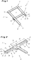
- plug-frame system 1 is already partially assembled to form a frame 2, wherein the finished frame 2 two Aufspannfelder 3 and 4 configured, in each of which a not shown insect screen gauze can be clamped.
- the plug-in frame system 1 consists essentially of a plurality of profile frame elements 5 (only exemplified, see in particular also FIG. 5 ) and a plurality of connector elements 6, by means of which immediately adjacent profile frame elements 5 are interconnected.
- the connector elements 6 are made in this embodiment of light metal casting.
- the profile frame elements 5 and the connector elements 6 together form the frame 2, wherein in this embodiment there are two types of connector elements 6, namely the corner connector elements 7 (only exemplified, see also FIG. 3 ), which connect only two profile frame elements 5 at right angles to each other, and if necessary additively the center connector elements 8 (only exemplified, see also FIG. 2 ), which two profile frame elements 5 are aligned with each other and additionally connect another profile frame element 5 at right angles to the two mutually aligned profile frame elements 5 with each other.
- the corner connector elements 7 only exemplified, see also FIG. 3
- the center connector elements 8 only exemplified, see also FIG. 2
- Each of the connector elements 6 has at least two insertion parts 10 (also numbered only as an example), on each of which a profile frame element 5 can be plugged.
- the profile frame elements 5 are designed as a continuous hollow chamber profile such that at its two respective ends 11 and 12 each have a Einsteckteilage 13 is available, in which the complementarily configured plug 10 can be inserted and set accordingly.
- the plug-in frame system 1 can also be equipped with pivotal fastening elements 14 and 15, by means of which the frame 2 can be mounted on a suitable support, such as a door or window frame.
- center connector element 8 has a total of three plug-in parts 10 and 16, of which the two aligned opposite plug-in parts 10 are configured identically.
- the two insertion parts 10 each have an elongated, flat basic body 17, which extends in the direction of the longitudinal extent 18 of the male member 10 extends outwardly from the central region 19 of the central connector member 8.
- the plug-in parts 10 thus each have a length 20 in the longitudinal extent 18, and a width 21 running transversely to the longitudinal extent 18 and height 22, wherein the length is greater than the width 21, and the width 21 is greater than the height 22.
- two broad sides 23 (numbered only by way of example), two narrow sides 24 (numbered only by way of example) and a head side 25 are defined on each of the insertion parts 10.
- Each elongate, flat plug-in part 10 is also divided into a clamping body section 30 and a guide rail section 31.
- the positioning of the two opposing guide grooves 33 and 34 are selected at the respective insertion part 10 such that the guide rail portion 31 in this embodiment, about one-third as wide as the clamp body portion 30.
- this subdivision is effected by means of two opposing guide grooves 32 and 33, which extend in each case on one of the broad sides 23 in the longitudinal extent 18.
- constricted connecting portion 34 may due to the targeted weakening of material by the two opposing guide grooves 32 and 33 with an appropriate choice of material immediately form an elastically configured connecting portion 34.
- the clamping body portion 30 and the guide rail portion 31 are structurally partially decoupled from each other, whereby the respective plug 10 is seen over its width 21 throughout is not so stiff, as without this intended arrangement of the guide grooves 32, 33.
- the guide grooves 32 and 33 serve not only the material weakening described herein and the effects thereby achieved on the respective plug 10.
- stiffening webs 35 and 36 in interaction with the guide grooves 32 and 33 not only take over the function of a stiffening of the profile frame elements 5 and thus also of the entire frame. 2
- stiffening webs 35 and 36 at the same time design linear guide components (not numbered separately) along which the plug-in part 10 can be inserted into the plug-in part receptacle 13.
- the present stiffening webs 35 and 36 in cooperation with the guide grooves 32 and 33 and the guide rail portion 31 form a guide device 40 (see in particular FIGS. 6 and 7 ).
- the stiffening webs 35, 36 are also arranged on the inner sides 37 of the profile frame member 5, that the Einsteckteilage 13 is divided into a first receiving portion 41 for receiving the clamping body portion 30 and a second receiving portion 42 for receiving the guide rail portion 31.
- the second receiving area 42 is formed flatter than the first receiving area 41, so that below the second receiving area 42 still a mounting bead 43 or the like can be placed.
- a retaining groove 44 is arranged, in which, for example, a welt element (not shown) of a fabric or an insect protection gauze can be fixed.
- the frame 2 produced by the present mating frame system 1 can be fastened to a component in a different manner, such as by means of the above-mentioned rotary fastening elements 14 and 15, which usually at least partially require a screw connection or the like.
- the frame 2 may alternatively be mounted by means of magnetic elements (not shown) and then also faster detachable to a component.
- Such magnetic elements can be structurally particularly advantageously integrated into the frame 2, since in the present case additional material recesses 50 are arranged in the clamping body section 30, in particular on the insertion part 10 next to the guide grooves 32 and 33.
- such additional material recesses 50 can also be arranged in the guide strip section 31 with a corresponding configuration of the insertion part 10.
- Eckverbinderelement shown 7 is also characterized by the fact that it has two identical insertion parts 10. These male parts 10 are in this case arranged on the central region 19 of the Eckverbinderelements 7, that they are aligned at right angles to each other. In this respect, they can a corner area (not separately numbered) of the frame 2 (see FIG. 1 ) well designed.
- the insertion parts 10 are dimensioned such that they are compatible with the smallest profile frame element 5, which has the narrowest Einsteckteilage 13.
- the plug-in frame system 1 can still be supplemented by adapter elements 55, as exemplified according to the illustration of the FIG. 4 is shown.
- the adapter element 55 shown as an example is U-shaped and can be used both on the corner connector element 7 and on the center connector element 8.
- the adapter element 55 is made of plastic and forms a kind of envelope for the insertion part 10.
- the adapter element 55 can be pushed laterally about the insertion part 10 approximately with its front side 56, so that the guide grooves 32 and 33 and the guide rail section 31 are not covered by the adapter element 55.
- the adapter element 55 also has a window cutout 57 in order to be able to ensure accessibility to the additional material recess 50 introduced in the plug-in part 10, even if the adapter element 55 has already been properly attached to the plug-in part 10.
- the adapter element 55 On its outer side 57, the adapter element 55 has a plurality of elongate sliding ribs 58 (numbered only as an example) in order to achieve a friction reduction when inserting the plug-in part 10 equipped with the adapter element 55 with respect to the inner sides 37 of the profile frame element 5. These sliding ribs 58 are distributed over the entire outer side 57. Thus, by means of the adapter member 55, the ease of assembly can be increased.
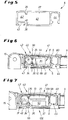
- the interaction or the interaction between the stiffening webs 35 and 36 and the guide grooves 32 and 33 is particularly easy to recognize, wherein the stiffening webs 35 and 36 and the guide grooves 32 and 33 are arranged in a common mounting plane 59, so that a partial decoupling between the clamping body portion 30 and the guide rail portion 31 is realized in a spatially narrow space.
- clamping body portion 30 is in the first receiving portion 41 and the guide rail portion 31 within the second receiving portion 42nd
- the adapter element 55 encloses the clamping body section 30 on the width sides 23 and on the narrow sides 24 of the insertion part 10, so that the insertion part 10 is clamped very well within the insertion part receptacle 13 of the profile frame element 5 in the region of the broad sides 23.
- the adapter element 55 and thus also the clamping body portion 30 is only via the sliding ribs 58 with the inner sides 37 of the profile frame member 5 in operative contact, whereby the insertion is greatly facilitated.
- the plug-in part 10 is clamped both with respect to the clamping body section 30 and with respect to the guide rail section 31 with respect to the profile frame element 5.
- the insertion part 10 experiences a certain elasticity transversely to the longitudinal extent 18 due to the constricted or elastic connection section 34 and in the direction of the width 21, whereby an insertion can be additionally facilitated.
- a veneer 60 is clipped on the profile frame element 5 as a cover.
- FIG. 7 is in the profile frame member 5, an alternative made of plastic connector element 106 in the form of a central connector element 108 (see. FIG. 8 ) plugged in.
- plastic insert element 10 in this regard is readily manufactured with sliding ribs 58 in an exact fit for the insertion part receptacle 13, a previously described additional adapter element 55 can be dispensed with.
- adapter element 55 may also be used with suitably configured alternative plastic universal connector elements.
- the sliding ribs 58 on the connector element 106 can be dispensed with here.
- an alternative connector element may be at least partially made of a metal core encapsulated with a plastic.
- the previously described adapter element 55 is immediately sprayed onto the plug-in part 10.
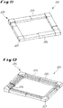
- the in the FIGS. 11 and 12 illustrated alternative frame 202 has a plurality of again reinforced profile frame members 205, which are connected by means of appropriately trained reinforced corner connector elements 207 with each other to the alternative frame 202, whereby the alternative frame 202 undergoes an even higher rigidity.
- This reinforcement is achieved by an additional profiling plane 269 of the reinforced corner connector elements 207 and the reinforced profile frame elements 205.
- four alternative facing elements 260 are clipped as a cover.
- the reinforced corner connector elements 207 in this case embody first connector elements 206 of the alternative frame 202.
- alternative corner connector element 307 is characterized by an additional insertion pin 370, which is additionally inserted into a receiving pocket (not shown) of a correspondingly complementary shaped profile frame member (not shown), if the other alternative corner connector element 307 common with the correspondingly complementary formed profile frame elements to a frame (not shown) are put together.
- This additional insertion pin 370 is aligned with a thinner plug 310A of the alternative corner connector 307.
- Additional material recesses 350 are additionally provided on the further alternative corner connector element 307 for weight reduction.
- the further alternative corner connector element 307 in this case embodies a first connector element 306.
- other corner connector element 407 also has an additional insertion pin 470, so that this other corner connector element 407 on a correspondingly complementary formed profile frame member 205 (see, for example FIGS. 11 and 12 ) is supported in addition to the two male parts 410A and 410B.
- the other corner connector element 407 also embodies a first connector element 406, as for example on the in the FIGS. 11 and 12 can be used playfully shown frame 202.
- Component 580 which is still shown, is a handle 581, which in particular faces the alternative frame 202 (see FIGS. 11 and 12 ) can be clipped, so that the frame 202, if it is rotatably suspended from a door frame or the like, is easier to use.
- the component 580 or the handle 581 has a clip part 582, by means of which it or it is clipped onto the alternative frame 202 from the outside.
- the component 580 or the handle 581 is still fixed to the alternative frame 202 by means of a screw (not shown) or the like.
- the component 580 or the handle 581 still a handle portion 583, by means of which he or he can be taken manually to operate the alternative frame 202.
Landscapes
- Engineering & Computer Science (AREA)
- Structural Engineering (AREA)
- Civil Engineering (AREA)
- Life Sciences & Earth Sciences (AREA)
- Insects & Arthropods (AREA)
- Pest Control & Pesticides (AREA)
- Architecture (AREA)
- Mutual Connection Of Rods And Tubes (AREA)
Claims (12)
- Système de cadre à emboîter (1) destiné à fabriquer un cadre (2 ; 202) servant à tendre en nappe un élément plan, notamment une gaze de moustiquaire, sur lequel le système de cadre à emboîter (1) comprend des profilés de cadre (5 ; 205) pour maintenir l'élément plan, ainsi que des éléments d'assemblage (6 ; 106 ; 206 ; 306 ; 406) pour assembler les profilés de cadre (5 ; 205), les éléments d'assemblage (6 ; 106 ; 206 ; 306 ; 406) comportant au moins deux pièces emboîtables (10 ; 310A ; 310B ; 410A ; 410B) et les profilés de cadre (5 ; 205) comportant deux logements (13) pour pièces emboîtables dans chacun desquels peut s'emboîter une pièce emboîtable (10 ; 310A ; 310B ; 410A ; 410B), de sorte que les profilés de cadre (5 ; 205) puissent être assemblés au moyen des éléments d'assemblage (6 ; 106 ; 206 ; 306 ; 406) pour former le cadre (2), caractérisé en ce que la pièce emboîtable (10 ; 310A ; 310B ; 410A ; 410B) est divisée en un segment formant corps de serrage (30 ; 330) et en un segment formant coulisse (31 ; 331), qui structurellement, sont partiellement découplés l'un par rapport à l'autre par deux rainures de guidage (32, 33 ; 332, 333) mutuellement opposées et en ce que le profilé de cadre (5 ; 205) comprend deux listels de renfort (35, 36) opposés dans un logement (13) pour pièce emboîtable, lesquels divisent le logement (13) pour pièce emboîtable en une première zone de logement (41) destinée à recevoir le segment formant corps de serrage (30 ; 330) et en une deuxième zone de logement (42), destinée à recevoir le segment formant coulisse (31 ; 331), en interaction avec les rainures de guidage (32, 33 ; 332 ; 333), les listels de renfort (35, 36) formant un système de guidage (40).
- Système de cadre à emboîter (1) selon la revendication 1, caractérisé en ce que les rainures de guidage (32, 33 ; 332, 333) mutuellement opposées et les listels de renfort (35, 36) mutuellement opposés sont placés dans un plan de montage (59) commun.
- Système de cadre à emboîter (1) selon la revendication 1 ou la revendication 2, caractérisé en ce que les rainures de guidage (32, 33 ; 332, 333) mutuellement opposées sont placées sur des côtés larges (23) de la pièce emboîtable (10 ; 310A ; 310B ; 410A ; 410B) et les listels de renfort (35, 36) mutuellement opposés sont placées sur les côtés larges du profilé de cadre (5 ; 205).
- Système de cadre à emboîter (1) selon la revendication 3, caractérisé en ce qu'aussi bien les rainures de guidage (32, 33 ; 332, 333) mutuellement opposées qu'également les listels de renfort (35, 36) mutuellement opposés sont placés de manière excentrée sur le côté large, en rapport à l'extension longitudinale respective de l'élément constitutif.
- Système de cadre à emboîter (1) selon l'une quelconque des revendications 1 à 4, caractérisé en ce que les rainures de guidage (32, 33 ; 332, 333) mutuellement opposées comportent chacune des contre-dépouilles dans lesquelles peuvent s'accrocher par l'arrière des tenons des listels de renfort (35, 36) mutuellement opposés.
- Système de cadre à emboîter (1) selon l'une quelconque des revendications 1 à 5, caractérisé en ce que le segment formant coulisse (31 ; 331) et le segment formant corps de serrage (30 ; 330) sont reliés l'un à l'autre au moyen d'un segment d'assemblage (34) étranglé.
- Système de cadre à emboîter (1) selon l'une quelconque des revendications 1 à 5, caractérisé en ce que le segment formant coulisse (31 ; 331) et le segment formant corps de serrage (30 ; 330) sont reliés l'un à l'autre par un segment d'assemblage (34) conçu de manière élastique.
- Système de cadre à emboîter (1) selon l'une quelconque des revendications 1 à 7, caractérisé en ce que le segment formant coulisse (31 ; 331) a une largeur correspondant à moins de la moitié, de préférence à un tiers de celle du segment formant corps de serrage (30).
- Système de cadre à emboîter (1) selon l'une quelconque des revendications 1 à 8, caractérisé en ce que latéralement, à côté des rainures de guidage (32, 33 ; 332, 333), des évidements de matière (50 ; 350) sont placés dans le segment formant corps de serrage (30 ; 330) et/ou dans le segment formant coulisse (31 ; 331).
- Système de cadre à emboîter (1) selon l'une quelconque des revendications 1 à 9, caractérisé par un élément adaptateur (55) lequel est placé au moins en partie entre la pièce emboîtable (10 ; 310A ; 310B ; 410A ; 410B) et des faces intérieures (37) du logement (13) pour pièce emboîtable.
- Système de cadre à emboîter (1) selon l'une quelconque des revendications 1 à 10, caractérisé en ce que les éléments d'assemblage (6 ; 106 ; 206 ; 306 ; 406) comprennent des éléments d'assemblage d'angle (7 ; 107 ; 207 ; 307 ; 407) et/ou des éléments d'assemblage centraux (8 ; 108).
- Système de cadre à emboîter (1) selon l'une quelconque des revendications 1 à 11, caractérisé en ce que les éléments d'assemblage (6 ; 106 ; 206 ; 306 ; 406) sont fabriqués en une fonte de métal léger, en une matière plastique ou au moins partiellement en un noyau métallique enrobé par injection d'une matière plastique.
Applications Claiming Priority (1)
| Application Number | Priority Date | Filing Date | Title |
|---|---|---|---|
| DE102014218466.5A DE102014218466B4 (de) | 2014-09-15 | 2014-09-15 | Steckrahmensystem |
Publications (2)
| Publication Number | Publication Date |
|---|---|
| EP3000957A1 EP3000957A1 (fr) | 2016-03-30 |
| EP3000957B1 true EP3000957B1 (fr) | 2017-05-17 |
Family
ID=54106238
Family Applications (1)
| Application Number | Title | Priority Date | Filing Date |
|---|---|---|---|
| EP15184750.6A Active EP3000957B1 (fr) | 2014-09-15 | 2015-09-10 | Systeme de cadre a enfichage |
Country Status (2)
| Country | Link |
|---|---|
| EP (1) | EP3000957B1 (fr) |
| DE (1) | DE102014218466B4 (fr) |
Families Citing this family (4)
| Publication number | Priority date | Publication date | Assignee | Title |
|---|---|---|---|---|
| US11952834B2 (en) * | 2019-07-31 | 2024-04-09 | Cavity Sliders Limited | Bracket |
| EP3875728B1 (fr) | 2020-03-02 | 2023-06-07 | Büdenbender, Arnd | Module de connecteur de profil et cadre doté d'un module de connecteur de profil |
| CN116928529A (zh) * | 2023-09-19 | 2023-10-24 | 贵州天地通科技有限公司 | 一种高精度测绘地理信息装置及其测绘方法 |
| DE102024105593A1 (de) * | 2024-02-28 | 2025-08-28 | Tesa Se | Moduleinheit für eine Rahmeneinheit einer Rahmenvorrichtung, Rahmenvorrichtung und Schutzsystem |
Family Cites Families (4)
| Publication number | Priority date | Publication date | Assignee | Title |
|---|---|---|---|---|
| DE102005048111A1 (de) * | 2005-10-06 | 2007-04-12 | Kochler, Manfred | Eckverbinder zum Verbinden zweier Hohl-Profilleisten |
| DE202006020221U1 (de) * | 2006-08-25 | 2008-03-20 | Tesa Ag | Rahmen, bevorzugter Weise Fliegengitterrahmen |
| DE102007021272A1 (de) * | 2006-10-30 | 2008-05-08 | Hecht International Gmbh | Profilstange für einen Insekten-Schutzgitter-Rahmen mit Magnetverschluß |
| DE102012023546B4 (de) * | 2012-12-01 | 2016-11-24 | M.A.C.'s Holding Gmbh | Rahmensystem für ein Insekten- und/oder Pollenschutzgitter |
-
2014
- 2014-09-15 DE DE102014218466.5A patent/DE102014218466B4/de not_active Expired - Fee Related
-
2015
- 2015-09-10 EP EP15184750.6A patent/EP3000957B1/fr active Active
Also Published As
| Publication number | Publication date |
|---|---|
| EP3000957A1 (fr) | 2016-03-30 |
| DE102014218466B4 (de) | 2016-05-12 |
| DE102014218466A1 (de) | 2016-03-17 |
Similar Documents
| Publication | Publication Date | Title |
|---|---|---|
| DE102012023546B4 (de) | Rahmensystem für ein Insekten- und/oder Pollenschutzgitter | |
| DE102007017100A1 (de) | Verbindungselement und Schutzabdeckung | |
| EP3000957B1 (fr) | Systeme de cadre a enfichage | |
| DE202015009191U1 (de) | Rahmenelement, Profilteil, Klemmleiste und Schutzgitter | |
| DE102015112563A1 (de) | Verbindungsanordnung zum Verbinden eines Pfostens an einem Rahmenprofil eines Fensters oder einer Türe aus Kunststoff | |
| DE20207426U1 (de) | Rahmengestell | |
| DE102012101117A1 (de) | Stangenschloss mit zusätzlicher Stangenstabilisierung | |
| DE202015105409U1 (de) | Insektenschutz-Rahmensystem | |
| DE102004054689A1 (de) | Befestigungsvorrichtung | |
| EP0312646A2 (fr) | Entretoise du milieu pour chambraules de fenêtre | |
| DE102008042922A1 (de) | Zaunklammer zur Befestigung eines Zaungitters an einem Pfosten | |
| DE2923903C2 (fr) | ||
| DE102013111815A1 (de) | Plisseejalousie | |
| AT512800A2 (de) | Rahmensystem für ein Insekten- und/oder Pollenschutzgitter | |
| EP3910155A1 (fr) | Dispositif de protection | |
| DE202009009498U1 (de) | Klammer für Kabelkanäle zur Kaschierung von Schnittkanten | |
| DE20107168U1 (de) | T-Verbindung zweier Profilstäbe | |
| DE202010013558U1 (de) | Scharnier für ein Insekten- und/oder Pollenschutzgitter | |
| WO2008068304A2 (fr) | Crémone | |
| CH687716A5 (de) | Beschlag. | |
| DE202013100898U1 (de) | Konstruktionseinheit, insbesondere für Möbel | |
| EP2853676A2 (fr) | Battant coulissant et installation coulissante de protection contre les insectes | |
| DE202007016892U1 (de) | Verbindungssystem für rinnenförmige Profilstäbe und Verbindungsanordnung | |
| DE202020101560U1 (de) | Halterungsvorrichtung | |
| WO2019020305A1 (fr) | Système de composants pour surfaces de présentation |
Legal Events
| Date | Code | Title | Description |
|---|---|---|---|
| PUAI | Public reference made under article 153(3) epc to a published international application that has entered the european phase |
Free format text: ORIGINAL CODE: 0009012 |
|
| AK | Designated contracting states |
Kind code of ref document: A1 Designated state(s): AL AT BE BG CH CY CZ DE DK EE ES FI FR GB GR HR HU IE IS IT LI LT LU LV MC MK MT NL NO PL PT RO RS SE SI SK SM TR |
|
| AX | Request for extension of the european patent |
Extension state: BA ME |
|
| 17P | Request for examination filed |
Effective date: 20160930 |
|
| RBV | Designated contracting states (corrected) |
Designated state(s): AL AT BE BG CH CY CZ DE DK EE ES FI FR GB GR HR HU IE IS IT LI LT LU LV MC MK MT NL NO PL PT RO RS SE SI SK SM TR |
|
| GRAP | Despatch of communication of intention to grant a patent |
Free format text: ORIGINAL CODE: EPIDOSNIGR1 |
|
| INTG | Intention to grant announced |
Effective date: 20161222 |
|
| GRAS | Grant fee paid |
Free format text: ORIGINAL CODE: EPIDOSNIGR3 |
|
| GRAA | (expected) grant |
Free format text: ORIGINAL CODE: 0009210 |
|
| AK | Designated contracting states |
Kind code of ref document: B1 Designated state(s): AL AT BE BG CH CY CZ DE DK EE ES FI FR GB GR HR HU IE IS IT LI LT LU LV MC MK MT NL NO PL PT RO RS SE SI SK SM TR |
|
| REG | Reference to a national code |
Ref country code: GB Ref legal event code: FG4D Free format text: NOT ENGLISH |
|
| REG | Reference to a national code |
Ref country code: CH Ref legal event code: EP |
|
| REG | Reference to a national code |
Ref country code: IE Ref legal event code: FG4D Free format text: LANGUAGE OF EP DOCUMENT: GERMAN |
|
| REG | Reference to a national code |
Ref country code: AT Ref legal event code: REF Ref document number: 894641 Country of ref document: AT Kind code of ref document: T Effective date: 20170615 |
|
| REG | Reference to a national code |
Ref country code: DE Ref legal event code: R096 Ref document number: 502015001076 Country of ref document: DE |
|
| REG | Reference to a national code |
Ref country code: NL Ref legal event code: FP |
|
| REG | Reference to a national code |
Ref country code: LT Ref legal event code: MG4D |
|
| PG25 | Lapsed in a contracting state [announced via postgrant information from national office to epo] |
Ref country code: FI Free format text: LAPSE BECAUSE OF FAILURE TO SUBMIT A TRANSLATION OF THE DESCRIPTION OR TO PAY THE FEE WITHIN THE PRESCRIBED TIME-LIMIT Effective date: 20170517 Ref country code: ES Free format text: LAPSE BECAUSE OF FAILURE TO SUBMIT A TRANSLATION OF THE DESCRIPTION OR TO PAY THE FEE WITHIN THE PRESCRIBED TIME-LIMIT Effective date: 20170517 Ref country code: NO Free format text: LAPSE BECAUSE OF FAILURE TO SUBMIT A TRANSLATION OF THE DESCRIPTION OR TO PAY THE FEE WITHIN THE PRESCRIBED TIME-LIMIT Effective date: 20170817 Ref country code: HR Free format text: LAPSE BECAUSE OF FAILURE TO SUBMIT A TRANSLATION OF THE DESCRIPTION OR TO PAY THE FEE WITHIN THE PRESCRIBED TIME-LIMIT Effective date: 20170517 Ref country code: GR Free format text: LAPSE BECAUSE OF FAILURE TO SUBMIT A TRANSLATION OF THE DESCRIPTION OR TO PAY THE FEE WITHIN THE PRESCRIBED TIME-LIMIT Effective date: 20170818 Ref country code: LT Free format text: LAPSE BECAUSE OF FAILURE TO SUBMIT A TRANSLATION OF THE DESCRIPTION OR TO PAY THE FEE WITHIN THE PRESCRIBED TIME-LIMIT Effective date: 20170517 |
|
| PG25 | Lapsed in a contracting state [announced via postgrant information from national office to epo] |
Ref country code: BG Free format text: LAPSE BECAUSE OF FAILURE TO SUBMIT A TRANSLATION OF THE DESCRIPTION OR TO PAY THE FEE WITHIN THE PRESCRIBED TIME-LIMIT Effective date: 20170817 Ref country code: LV Free format text: LAPSE BECAUSE OF FAILURE TO SUBMIT A TRANSLATION OF THE DESCRIPTION OR TO PAY THE FEE WITHIN THE PRESCRIBED TIME-LIMIT Effective date: 20170517 Ref country code: PL Free format text: LAPSE BECAUSE OF FAILURE TO SUBMIT A TRANSLATION OF THE DESCRIPTION OR TO PAY THE FEE WITHIN THE PRESCRIBED TIME-LIMIT Effective date: 20170517 Ref country code: SE Free format text: LAPSE BECAUSE OF FAILURE TO SUBMIT A TRANSLATION OF THE DESCRIPTION OR TO PAY THE FEE WITHIN THE PRESCRIBED TIME-LIMIT Effective date: 20170517 Ref country code: IS Free format text: LAPSE BECAUSE OF FAILURE TO SUBMIT A TRANSLATION OF THE DESCRIPTION OR TO PAY THE FEE WITHIN THE PRESCRIBED TIME-LIMIT Effective date: 20170917 Ref country code: RS Free format text: LAPSE BECAUSE OF FAILURE TO SUBMIT A TRANSLATION OF THE DESCRIPTION OR TO PAY THE FEE WITHIN THE PRESCRIBED TIME-LIMIT Effective date: 20170517 |
|
| PG25 | Lapsed in a contracting state [announced via postgrant information from national office to epo] |
Ref country code: DK Free format text: LAPSE BECAUSE OF FAILURE TO SUBMIT A TRANSLATION OF THE DESCRIPTION OR TO PAY THE FEE WITHIN THE PRESCRIBED TIME-LIMIT Effective date: 20170517 Ref country code: RO Free format text: LAPSE BECAUSE OF FAILURE TO SUBMIT A TRANSLATION OF THE DESCRIPTION OR TO PAY THE FEE WITHIN THE PRESCRIBED TIME-LIMIT Effective date: 20170517 Ref country code: EE Free format text: LAPSE BECAUSE OF FAILURE TO SUBMIT A TRANSLATION OF THE DESCRIPTION OR TO PAY THE FEE WITHIN THE PRESCRIBED TIME-LIMIT Effective date: 20170517 Ref country code: CZ Free format text: LAPSE BECAUSE OF FAILURE TO SUBMIT A TRANSLATION OF THE DESCRIPTION OR TO PAY THE FEE WITHIN THE PRESCRIBED TIME-LIMIT Effective date: 20170517 Ref country code: SK Free format text: LAPSE BECAUSE OF FAILURE TO SUBMIT A TRANSLATION OF THE DESCRIPTION OR TO PAY THE FEE WITHIN THE PRESCRIBED TIME-LIMIT Effective date: 20170517 |
|
| REG | Reference to a national code |
Ref country code: DE Ref legal event code: R097 Ref document number: 502015001076 Country of ref document: DE |
|
| PG25 | Lapsed in a contracting state [announced via postgrant information from national office to epo] |
Ref country code: IT Free format text: LAPSE BECAUSE OF FAILURE TO SUBMIT A TRANSLATION OF THE DESCRIPTION OR TO PAY THE FEE WITHIN THE PRESCRIBED TIME-LIMIT Effective date: 20170517 Ref country code: SM Free format text: LAPSE BECAUSE OF FAILURE TO SUBMIT A TRANSLATION OF THE DESCRIPTION OR TO PAY THE FEE WITHIN THE PRESCRIBED TIME-LIMIT Effective date: 20170517 |
|
| PLBE | No opposition filed within time limit |
Free format text: ORIGINAL CODE: 0009261 |
|
| STAA | Information on the status of an ep patent application or granted ep patent |
Free format text: STATUS: NO OPPOSITION FILED WITHIN TIME LIMIT |
|
| 26N | No opposition filed |
Effective date: 20180220 |
|
| PG25 | Lapsed in a contracting state [announced via postgrant information from national office to epo] |
Ref country code: MC Free format text: LAPSE BECAUSE OF FAILURE TO SUBMIT A TRANSLATION OF THE DESCRIPTION OR TO PAY THE FEE WITHIN THE PRESCRIBED TIME-LIMIT Effective date: 20170517 Ref country code: SI Free format text: LAPSE BECAUSE OF FAILURE TO SUBMIT A TRANSLATION OF THE DESCRIPTION OR TO PAY THE FEE WITHIN THE PRESCRIBED TIME-LIMIT Effective date: 20170517 |
|
| REG | Reference to a national code |
Ref country code: IE Ref legal event code: MM4A |
|
| REG | Reference to a national code |
Ref country code: FR Ref legal event code: ST Effective date: 20180531 |
|
| PG25 | Lapsed in a contracting state [announced via postgrant information from national office to epo] |
Ref country code: IE Free format text: LAPSE BECAUSE OF NON-PAYMENT OF DUE FEES Effective date: 20170910 |
|
| PG25 | Lapsed in a contracting state [announced via postgrant information from national office to epo] |
Ref country code: FR Free format text: LAPSE BECAUSE OF NON-PAYMENT OF DUE FEES Effective date: 20171002 |
|
| PG25 | Lapsed in a contracting state [announced via postgrant information from national office to epo] |
Ref country code: MT Free format text: LAPSE BECAUSE OF FAILURE TO SUBMIT A TRANSLATION OF THE DESCRIPTION OR TO PAY THE FEE WITHIN THE PRESCRIBED TIME-LIMIT Effective date: 20170517 |
|
| PG25 | Lapsed in a contracting state [announced via postgrant information from national office to epo] |
Ref country code: HU Free format text: LAPSE BECAUSE OF FAILURE TO SUBMIT A TRANSLATION OF THE DESCRIPTION OR TO PAY THE FEE WITHIN THE PRESCRIBED TIME-LIMIT; INVALID AB INITIO Effective date: 20150910 |
|
| PG25 | Lapsed in a contracting state [announced via postgrant information from national office to epo] |
Ref country code: CY Free format text: LAPSE BECAUSE OF FAILURE TO SUBMIT A TRANSLATION OF THE DESCRIPTION OR TO PAY THE FEE WITHIN THE PRESCRIBED TIME-LIMIT Effective date: 20170517 |
|
| PG25 | Lapsed in a contracting state [announced via postgrant information from national office to epo] |
Ref country code: MK Free format text: LAPSE BECAUSE OF FAILURE TO SUBMIT A TRANSLATION OF THE DESCRIPTION OR TO PAY THE FEE WITHIN THE PRESCRIBED TIME-LIMIT Effective date: 20170517 |
|
| PG25 | Lapsed in a contracting state [announced via postgrant information from national office to epo] |
Ref country code: TR Free format text: LAPSE BECAUSE OF FAILURE TO SUBMIT A TRANSLATION OF THE DESCRIPTION OR TO PAY THE FEE WITHIN THE PRESCRIBED TIME-LIMIT Effective date: 20170517 |
|
| PG25 | Lapsed in a contracting state [announced via postgrant information from national office to epo] |
Ref country code: PT Free format text: LAPSE BECAUSE OF FAILURE TO SUBMIT A TRANSLATION OF THE DESCRIPTION OR TO PAY THE FEE WITHIN THE PRESCRIBED TIME-LIMIT Effective date: 20170517 |
|
| PG25 | Lapsed in a contracting state [announced via postgrant information from national office to epo] |
Ref country code: AL Free format text: LAPSE BECAUSE OF FAILURE TO SUBMIT A TRANSLATION OF THE DESCRIPTION OR TO PAY THE FEE WITHIN THE PRESCRIBED TIME-LIMIT Effective date: 20170517 |
|
| GBPC | Gb: european patent ceased through non-payment of renewal fee |
Effective date: 20190910 |
|
| PG25 | Lapsed in a contracting state [announced via postgrant information from national office to epo] |
Ref country code: GB Free format text: LAPSE BECAUSE OF NON-PAYMENT OF DUE FEES Effective date: 20190910 |
|
| REG | Reference to a national code |
Ref country code: CH Ref legal event code: U11 Free format text: ST27 STATUS EVENT CODE: U-0-0-U10-U11 (AS PROVIDED BY THE NATIONAL OFFICE) Effective date: 20251001 |
|
| PGFP | Annual fee paid to national office [announced via postgrant information from national office to epo] |
Ref country code: DE Payment date: 20250919 Year of fee payment: 11 |
|
| PGFP | Annual fee paid to national office [announced via postgrant information from national office to epo] |
Ref country code: NL Payment date: 20250922 Year of fee payment: 11 Ref country code: LU Payment date: 20250922 Year of fee payment: 11 |
|
| PGFP | Annual fee paid to national office [announced via postgrant information from national office to epo] |
Ref country code: BE Payment date: 20250919 Year of fee payment: 11 |
|
| PGFP | Annual fee paid to national office [announced via postgrant information from national office to epo] |
Ref country code: AT Payment date: 20250918 Year of fee payment: 11 |
|
| REG | Reference to a national code |
Ref country code: DE Ref legal event code: R082 Ref document number: 502015001076 Country of ref document: DE Representative=s name: DIPAS PATENTANWALTS GMBH, DE |
|
| PGFP | Annual fee paid to national office [announced via postgrant information from national office to epo] |
Ref country code: CH Payment date: 20251001 Year of fee payment: 11 |
|
| REG | Reference to a national code |
Ref country code: DE Ref legal event code: R081 Ref document number: 502015001076 Country of ref document: DE Owner name: BASH-TEC GMBH, DE Free format text: FORMER OWNER: BUEDENBENDER, ARND, 57250 NETPHEN, DE |