EP3000974A1 - Moulage optimisé pour améliorer la performance des trous formés de refroidissement côté aspiration - Google Patents
Moulage optimisé pour améliorer la performance des trous formés de refroidissement côté aspiration Download PDFInfo
- Publication number
- EP3000974A1 EP3000974A1 EP15183559.2A EP15183559A EP3000974A1 EP 3000974 A1 EP3000974 A1 EP 3000974A1 EP 15183559 A EP15183559 A EP 15183559A EP 3000974 A1 EP3000974 A1 EP 3000974A1
- Authority
- EP
- European Patent Office
- Prior art keywords
- wall
- cooling hole
- gas turbine
- turbine engine
- protrusion
- Prior art date
- Legal status (The legal status is an assumption and is not a legal conclusion. Google has not performed a legal analysis and makes no representation as to the accuracy of the status listed.)
- Withdrawn
Links
Images


Classifications
-
- F—MECHANICAL ENGINEERING; LIGHTING; HEATING; WEAPONS; BLASTING
- F01—MACHINES OR ENGINES IN GENERAL; ENGINE PLANTS IN GENERAL; STEAM ENGINES
- F01D—NON-POSITIVE DISPLACEMENT MACHINES OR ENGINES, e.g. STEAM TURBINES
- F01D9/00—Stators
- F01D9/02—Nozzles; Nozzle boxes; Stator blades; Guide conduits, e.g. individual nozzles
- F01D9/023—Transition ducts between combustor cans and first stage of the turbine in gas-turbine engines; their cooling or sealings
-
- F—MECHANICAL ENGINEERING; LIGHTING; HEATING; WEAPONS; BLASTING
- F01—MACHINES OR ENGINES IN GENERAL; ENGINE PLANTS IN GENERAL; STEAM ENGINES
- F01D—NON-POSITIVE DISPLACEMENT MACHINES OR ENGINES, e.g. STEAM TURBINES
- F01D5/00—Blades; Blade-carrying members; Heating, heat-insulating, cooling or antivibration means on the blades or the members
- F01D5/12—Blades
- F01D5/14—Form or construction
- F01D5/18—Hollow blades, i.e. blades with cooling or heating channels or cavities; Heating, heat-insulating or cooling means on blades
- F01D5/186—Film cooling
-
- F—MECHANICAL ENGINEERING; LIGHTING; HEATING; WEAPONS; BLASTING
- F01—MACHINES OR ENGINES IN GENERAL; ENGINE PLANTS IN GENERAL; STEAM ENGINES
- F01D—NON-POSITIVE DISPLACEMENT MACHINES OR ENGINES, e.g. STEAM TURBINES
- F01D5/00—Blades; Blade-carrying members; Heating, heat-insulating, cooling or antivibration means on the blades or the members
- F01D5/12—Blades
- F01D5/14—Form or construction
- F01D5/18—Hollow blades, i.e. blades with cooling or heating channels or cavities; Heating, heat-insulating or cooling means on blades
- F01D5/187—Convection cooling
- F01D5/188—Convection cooling with an insert in the blade cavity to guide the cooling fluid, e.g. forming a separation wall
- F01D5/189—Convection cooling with an insert in the blade cavity to guide the cooling fluid, e.g. forming a separation wall the insert having a tubular cross-section, e.g. airfoil shape
-
- F—MECHANICAL ENGINEERING; LIGHTING; HEATING; WEAPONS; BLASTING
- F01—MACHINES OR ENGINES IN GENERAL; ENGINE PLANTS IN GENERAL; STEAM ENGINES
- F01D—NON-POSITIVE DISPLACEMENT MACHINES OR ENGINES, e.g. STEAM TURBINES
- F01D9/00—Stators
- F01D9/02—Nozzles; Nozzle boxes; Stator blades; Guide conduits, e.g. individual nozzles
- F01D9/04—Nozzles; Nozzle boxes; Stator blades; Guide conduits, e.g. individual nozzles forming ring or sector
- F01D9/041—Nozzles; Nozzle boxes; Stator blades; Guide conduits, e.g. individual nozzles forming ring or sector using blades
-
- F—MECHANICAL ENGINEERING; LIGHTING; HEATING; WEAPONS; BLASTING
- F05—INDEXING SCHEMES RELATING TO ENGINES OR PUMPS IN VARIOUS SUBCLASSES OF CLASSES F01-F04
- F05D—INDEXING SCHEME FOR ASPECTS RELATING TO NON-POSITIVE-DISPLACEMENT MACHINES OR ENGINES, GAS-TURBINES OR JET-PROPULSION PLANTS
- F05D2250/00—Geometry
- F05D2250/30—Arrangement of components
- F05D2250/31—Arrangement of components according to the direction of their main axis or their axis of rotation
- F05D2250/314—Arrangement of components according to the direction of their main axis or their axis of rotation the axes being inclined in relation to each other
-
- F—MECHANICAL ENGINEERING; LIGHTING; HEATING; WEAPONS; BLASTING
- F05—INDEXING SCHEMES RELATING TO ENGINES OR PUMPS IN VARIOUS SUBCLASSES OF CLASSES F01-F04
- F05D—INDEXING SCHEME FOR ASPECTS RELATING TO NON-POSITIVE-DISPLACEMENT MACHINES OR ENGINES, GAS-TURBINES OR JET-PROPULSION PLANTS
- F05D2250/00—Geometry
- F05D2250/70—Shape
- F05D2250/71—Shape curved
- F05D2250/712—Shape curved concave
-
- F—MECHANICAL ENGINEERING; LIGHTING; HEATING; WEAPONS; BLASTING
- F05—INDEXING SCHEMES RELATING TO ENGINES OR PUMPS IN VARIOUS SUBCLASSES OF CLASSES F01-F04
- F05D—INDEXING SCHEME FOR ASPECTS RELATING TO NON-POSITIVE-DISPLACEMENT MACHINES OR ENGINES, GAS-TURBINES OR JET-PROPULSION PLANTS
- F05D2260/00—Function
- F05D2260/20—Heat transfer, e.g. cooling
- F05D2260/201—Heat transfer, e.g. cooling by impingement of a fluid
-
- Y—GENERAL TAGGING OF NEW TECHNOLOGICAL DEVELOPMENTS; GENERAL TAGGING OF CROSS-SECTIONAL TECHNOLOGIES SPANNING OVER SEVERAL SECTIONS OF THE IPC; TECHNICAL SUBJECTS COVERED BY FORMER USPC CROSS-REFERENCE ART COLLECTIONS [XRACs] AND DIGESTS
- Y02—TECHNOLOGIES OR APPLICATIONS FOR MITIGATION OR ADAPTATION AGAINST CLIMATE CHANGE
- Y02T—CLIMATE CHANGE MITIGATION TECHNOLOGIES RELATED TO TRANSPORTATION
- Y02T50/00—Aeronautics or air transport
- Y02T50/60—Efficient propulsion technologies, e.g. for aircraft
Definitions
- the present disclosure relates generally to a gas turbine engine and more specifically to turbine blades and/or vanes exposed to high temperature.
- a gas turbine engine may include a turbine section with multiple rows or stages of stator vanes and rotor blades that interact or react with a high temperature gas flow to create mechanical power.
- the turbine rotor blades drive the compressor and an electric generator to generate electrical power.
- These stator vanes and rotor blades are cooled by cooling holes through the surface of the vanes and blades.
- the efficiency of the engine can be increased by passing a higher temperature gas flow through the turbine.
- the turbine inlet temperature is limited by the vane and blade (airfoils) material properties and the cooling capabilities of these airfoils.
- the temperature of the gas flow passing through the turbine progressively decreases as the rotor blade stages extract energy from the gas flow.
- the component includes a pressure side, a suction side, a leading edge, a trailing edge, an outer surface and an inner surface.
- the inner surface is positioned within the outer surface and defines a core.
- the inner surface has a first protrusion.
- the engine includes a compressor section, a combustor section and a turbine section.
- the turbine section includes a component that includes a pressure side, a suction side, a leading edge, a trailing edge, an outer surface and an inner surface.
- the inner surface is positioned within the outer surface and defines a core.
- the inner surface has a first protrusion.
- the component includes a pressure side, a suction side, a leading edge, a trailing edge, an outer surface and an inner surface.
- the inner surface is positioned within the outer surface and defines a core.
- the inner surface has a first face positioned on the suction side.
- the first face has a first distance to the outer surface that is larger than a second distance to the outer surface.
- the second distance is positioned towards the leading edge from the first distance.
- the component also has a first cooling hole extending from the outer surface to the first face.
- the first cooling hole has a first metering axis that forms an angle between 15 degrees and 40 degrees with a first portion of the outer surface that is adjacent the first cooling hole.
- tail refers to the direction associated with the tail (e.g., the back end) of an aircraft, or generally, to the direction of exhaust of the gas turbine engine.
- forward refers to the direction associated with the nose (e.g., the front end) of an aircraft, or generally, to the direction of flight or motion.
- Gas turbine engine 20 may be a two-spool turbofan that generally incorporates a fan section 22, a compressor section 24, a combustor section 26 and a turbine section 28.
- Alternative engines may include, for example, an augmentor section among other systems or features.
- fan section 22 can drive air along a bypass flow-path B while compressor section 24 can drive air along a core flow-path C for compression and communication into combustor section 26 then expansion through turbine section 28.
- turbofan gas turbine engine 20 depicted as a turbofan gas turbine engine 20 herein, it should be understood that the concepts described herein are not limited to use with turbofans as the teachings may be applied to other types of turbine engines including three-spool architectures.
- Gas turbine engine 20 may generally comprise a low speed spool 30 and a high speed spool 32 mounted for rotation about an engine central longitudinal axis A-A' relative to an engine static structure 36 via several bearing systems 38, 38-1, and 38-2. It should be understood that various bearing systems 38 at various locations may alternatively or additionally be provided, including for example, bearing system 38, bearing system 38-1, and bearing system 38-2.
- Low speed spool 30 may generally comprise an inner shaft 40 that interconnects a fan 42, a low pressure (or first) compressor section 44 and a low pressure (or first) turbine section 46.
- Inner shaft 40 may be connected to fan 42 through a geared architecture 48 that can drive fan 42 at a lower speed than low speed spool 30.
- Geared architecture 48 may comprise a gear assembly 60 enclosed within a gear housing 62.
- Gear assembly 60 couples inner shaft 40 to a rotating fan structure.
- High speed spool 32 may comprise an outer shaft 50 that interconnects a high pressure (or second) compressor section 52 and high pressure (or second) turbine section 54.
- a combustor 56 may be located between high pressure compressor 52 and high pressure turbine 54.
- a mid-turbine frame 57 of engine static structure 36 may be located generally between high pressure turbine 54 and low pressure turbine 46.
- Mid-turbine frame 57 may support one or more bearing systems 38 in turbine section 28.
- Inner shaft 40 and outer shaft 50 may be concentric and rotate via bearing systems 38 about the engine central longitudinal axis A-A', which is collinear with their longitudinal axes.
- a "high pressure" compressor or turbine experiences a higher pressure than a corresponding "low pressure” compressor or turbine.
- the core airflow C may be compressed by low pressure compressor section 44 then high pressure compressor 52, mixed and burned with fuel in combustor 56, then expanded over high pressure turbine 54 and low pressure turbine 46.
- Mid-turbine frame 57 includes airfoils 59 which are in the core airflow path. Turbines 46, 54 rotationally drive the respective low speed spool 30 and high speed spool 32 in response to the expansion.
- Gas turbine engine 20 may be, for example, a high-bypass geared aircraft engine. In various embodiments, the bypass ratio of gas turbine engine 20 may be greater than about six (6). In various embodiments, the bypass ratio of gas turbine engine 20 may be greater than ten (10).
- geared architecture 48 may be an epicyclic gear train, such as a star gear system (sun gear in meshing engagement with a plurality of star gears supported by a carrier and in meshing engagement with a ring gear) or other gear system. Gear architecture 48 may have a gear reduction ratio of greater than about 2.3 and low pressure turbine 46 may have a pressure ratio that is greater than about 5. In various embodiments, the bypass ratio of gas turbine engine 20 is greater than about ten (10:1).
- the diameter of fan 42 may be significantly larger than that of the low pressure compressor section 44, and the low pressure turbine 46 may have a pressure ratio that is greater than about 5:1. Low pressure turbine 46 pressure ratio may be measured prior to inlet of low pressure turbine 46 as related to the pressure at the outlet of low pressure turbine 46 prior to an exhaust nozzle. It should be understood, however, that the above parameters are exemplary of various embodiments of a suitable geared architecture engine and that the present disclosure contemplates other turbine engines including direct drive turbofans.
- the next generation of turbofan engines may be designed for higher efficiency which requires higher pressure ratios and higher temperatures in high pressure compressor 52. These higher operating temperatures and pressure ratios may create operating environments that may cause thermal loads that are higher than the thermal loads which may shorten the endurance life of current components.
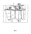
- high pressure turbine 54 may comprise alternating rows of rotors 64 and stators 66 (shown as stator 66-1 and stator 66-2 in FIG. 2 ).
- Stators 66 or rotors 64 may be simply supported or cantilevered and have a shrouded configuration as shown in FIG. 2 .
- stator 66-1 may comprise a stator vane 65, a casing support and a hub support.
- stator vane 65 may be supported along an outer diameter by casing support and along an inner diameter hub support.
- a cantilevered stator may comprise a stator vane that is only retained and/or supported at the casing (e.g., an outer diameter).
- rotors 64 may harvest energy from a fluid flow.
- Stators 66 may be configured to receive and straighten the fluid flow.
- the fluid flow discharged from the trailing edge of stators 66 may be straightened (e.g., the flow may be directed in a substantially parallel path to the centerline of the engine and/or HPT) to increase and/or improve the efficiency of the engine and, more specifically, to achieve maximum and/or near maximum energy harvesting and efficiency when the straightened air is received by rotors 64.
- FIGs. 3 and 4 illustrate an enlarged view of vane 65.
- FIG. 3 illustrates vane 65 without a cooling tube or insert and
- FIG. 4 illustrates vane 65 with a cooling tube or insert 117.
- Cooling tube or insert 117 is a tube or material insert that delivers cooling flow from an inner diameter or outer diameter region of vane 65 outside of the flowpath. The air flows into vane 65 within the cooling tube and discharges through impingement holes on the backside of vane 65. The impingement cooling causes convective heat transfer and cools vane 65 along with cooling from cooling holes.
- Vane 65 has a suction side 101, a pressure side 103, a leading edge 105 and a trailing edge 107.
- Leading edge 105 may reference the edge at which hot gas flow directly hits vane 65.
- Pressure side 103 is positioned in an area of higher pressure than suction side 101.
- Vane 65 includes a wall 102 formed from a material such as a metal (e.g., a nickel or cobalt based super alloy, an austenitic nickel-chromium-based alloy such as Inconel® which is available from Special Metals Corporation of New Hartford, New York, USA, composite materials, and other suitable materials).
- Wall 102 includes an inner surface 110 and an outer surface 108.
- Inner surface 110 defines a leading edge core 109 of vane 65.
- Wall 102 may also include an inner surface 123 defining a trailing edge core 111.
- Outer surface 108 is disposed outward of and circumscribes leading edge core 109 and trailing edge core 111.
- vane 65 may define any number of cores, including one, two, three, etc.
- the term "inward” references a direction towards the center of leading edge core 109 (illustrated by arrow 113) and outward references a direction away from the center of leading edge core 109 (illustrated by arrow 115).
- vane 65 includes inward extending protrusions 104a, 104b on inner surface 110.
- Inward protrusions 104 may be comprised of the same material as the rest of vane 65.
- Inward protrusions 104 can be formed, for example, at the same time as vane 65 or can be formed separately.
- Inward protrusions 104 and/or vane 65 can be formed using additive or subtractive manufacturing.
- inward protrusions 104 and/or vane 65 can be formed using casting or internally machined using electrode discharge machining, chemical machining or convection machining.
- any number of inward protrusions 104 can be included in vane 65.
- Inward protrusions 104 are not limited to extending within core 109, and can be formed within any core.
- wall 102 defines suction side cooling hole 106a, suction side cooling hole 106b, and pressure side cooling holes 112.
- any number of suction side cooling holes 106 and any number of pressure side cooling holes 112 may be included in vane 65.
- Cooling holes 106 and/or cooling holes 112 can be made, for example, using an electrode discharge machine (EDM), laser drilling, or any other method of forming holes in wall 102.
- vane 65 may be formed by additive manufacturing with cooling holes 106 and/or cooling holes 112 created by the additive manufacturing process. Cooling holes 106, 112 are discussed below in more detail.
- a wall of a vane or other airfoil has a constant width throughout, and includes an inner surface which is smooth. This width is set by various constraints, such as thermal properties of the component material, weight, etc.
- width W1 of wall 102 of vane 65 is not constant throughout. In certain locations along vane 65, less heat, pressure, etc. is applied to vane 65. Because of this, width W1 of wall 102 may be altered in certain locations in order to optimize cooling of vane 65 as illustrated in FIGs. 5 and 6A , which best illustrate, respectively, portion 200 of wall 102 around cooling hole 106b and portion 300 of wall 102 around cooling hole 106a.
- cooling hole 106b has an outlet 118b and an inlet 116b. Cool (relative to the air temperature proximate pressure side 103 during typical operation) air enters cooling hole 106b, travels through cooling hole 106b, and exits through outlet 118b. Inlet 116b is chamfered to increase air flow through cooling hole 106b.
- Cooling hole 106b has a metering portion 120b having a meter length (length) MLb.
- Metering portion 120b also has a meter diameter MWb.
- Width MDb is generally constant throughout metering portion 120b, however, in various embodiments, width MDb may increase or decrease as it approaches inlet 116b.
- Metering portion 120 has an axis Ab.
- Metering portion 120 may have a circumference (radial to axis Ab) that has any shape, such as oval, circular, square, rectangular, etc. In various embodiments, metering portion 120b may be an internal diffuser.
- Cooling hole 106b may also have an outer diffuser portion 122b.
- Diffuser portion 122b may have a width (width) DWb that increases as it approaches outer surface 108. Diffuser portion 122b may allow cool air to diffuse prior to entering the main gas path.
- Diffuser portion 122b may have a circumferential shape (radial to a central axis) that has any shape, such as oval, circular, flattened oval, square, rectangular, or complex shape as illustrated, for example, in U.S. Patent No 8,584,470 B2 .
- the shape of the circumference of diffuser portion 122b may change depending on the location along axis Ab. For example, the shape may be circular near metering portion 120b yet be oval near inlet 116b.
- cooling holes in an airfoil are perpendicular to wall 102 on suction side 101.
- cooling holes can have increased length, and thus surface area, through wall 102. This extra surface area provides increased convection.
- Angled cooling holes also direct coolant towards leading edge 105 where vane 65 may be subject to a high level of heat. Including inward protrusions 104 into wall 102 facilitates the inclusion of angled cooling holes into wall 102, as cooling holes 106 can be drilled without scarfing inner surface 110.
- inward protrusion 104b of wall 102 extends inward within leading edge core 109 on inner surface 110.
- Wall 102 has a width W2b ( FIG. 5 ) at the end of inward protrusion 104b near an outwardly extending concavity 124b. Width W2b is larger than width W1.
- Inward protrusion 104b creates at least part of a wall 126b, or face, that partially faces towards leading edge 105 and/or pressure side 103. The positioning of wall 126b facilitates outlet 118b facing leading edge 105.
- Wall 126b may be a flat surface or may have curvature.
- Inner surface 110 also defines an outwardly extending concavity 124b toward outer surface 108.
- outward concavity 124b is adjacent inward protrusion 104b.
- Wall 102 has a width W3b at the beginning of outward concavity 124b nearest inward protrusion 104b that is smaller than width W1.
- Width W1, W2 and W3 are sized for the pressure delta across wall 102. Pressure drop across wall 102 proximate outward concavity 124b is relatively small. Certain portions of wall 102 may be exposed to relatively large pressure differentials. Therefore, consideration of pressure delta across wall 102 must be taken into account when determining width W3b of outward concavity 124b.
- cooling hole 106b, inward protrusion 104b and outward concavity 124b may be positioned anywhere on suction side 101 of vane 65. For example, they may be positioned near leading edge 105, near trailing edge 107, near the middle, etc.
- cooling hole 106b, inward protrusion 104b and outward concavity 124b, size, shape, angles, etc. of these elements will need to be altered based on pressure exposure, temperature exposure, curvature of inner surface 110 and/or outer surface 108, desired angle ⁇ , etc.
- cooling hole 106b, inward protrusion 104b and outward concavity 124b are positioned on suction side 101 of vane 65 such that cooling hole 106b is positioned between suction side 101 and leading edge core 109. In various embodiments, cooling hole 106b, inward protrusion 104b and outward concavity 124b are positioned closer to leading edge 105 than trailing edge core 111.
- inward protrusion 104b or outward concavity 124b may exist. In various embodiments, inward and/or outward concavity may be applied to wall 102 on pressure side 103 of vane 65.
- Inward protrusion 104b and outward concavity 124b define wall 126b that defines outlet 118b. In various embodiments, only inward protrusion 104b may exist and define wall 126b. In various embodiments, only outward concavity 124b may exist and define wall 126b. Wall 126b may exist from an apex of inward protrusion 104b to an apex of outward concavity 124b.
- an angle ⁇ between wall 126b and axis Ab can be large, nearing 90 degrees, while angle ⁇ can be small, such as below 45 degrees. In various embodiments, angle ⁇ can be larger or smaller than 90 degrees. If vane 65 were to not include inward protrusion 104b and/or outward concavity 124b, then angle ⁇ would be limited to at least 45 degrees and above. However, inward protrusion 104b and/or outward concavity 124b allow angle ⁇ to range from 15 degrees to 40 degrees. The facilitation of a lower angle ⁇ allows the metering portion of cooling hole 106b to become elongated.
- inward protrusion 104b and/or outward concavity 124b may be designed such that they define wall 126b based on a desired angle ⁇ .
- axis Ab may be perpendicular to wall 126b. In various embodiments, axis Ab may not be perpendicular to wall 126b.
- wall 126b is perpendicular to inner surface 110. In various embodiments, wall 126b may form an acute or obtuse angle with inner surface 110.
- inward protrusion 104b has an angled edge that is near 90 degrees. In various embodiments, inward protrusion 104b may have an edge having an acute or obtuse angle. In various embodiments, inward protrusion 104b may be rounded instead of angled.
- outward concavity 124b has a rounded edge. In various embodiments, outward concavity 124b may have an angled edge being 90 degrees, acute or obtuse.
- Angle ⁇ may be an angle less than 90 degrees.
- angle ⁇ is between 15 degrees and 40 degrees.
- angle ⁇ is between 18 degrees and 30 degrees.
- angle ⁇ is between 18 and 20 degrees.
- cooling hole 106b may have a ratio of meter length MLb to meter diameter MDb that is greater than two and a half to one (2.5:1).
- cooling hole 106b performance illustrates the importance of providing cooling holes defined at a greater angle to wall 102. If angle ⁇ is large, then cooling hole 106b may be nearly perpendicular to inner surface 110 and outer surface 108. The more perpendicular cooling hole 106b is to wall 102 (i.e., the larger angle ⁇ is), the more prone cooling hole 106b will be to blow off and lower film effectiveness. If cooling hole 106b is perpendicular to wall 102, meter length MLb will be relatively small (as it will be nearly the distance W1, which is relatively short). A relatively small meter length MLb will result in a smaller ratio of meter length MLb to meter diameter MDb.
- cooling hole 106b can extend for a longer distance between inner surface 110 and outer surface 108. This elongated distance of cooling hole 106b allows for meter length MLb to become larger, thus increasing performance of cooling hole 106b.
- cooling hole 106a has an outlet 118a and an inlet 116a. Cool (relative to the air temperature proximate pressure side 103 during typical operation) air enters cooling hole 106a, travels through cooling hole 106a and exits through outlet 118a. Inlet 116a is chamfered for improved coolant flow through cooling hole 106a.
- Cooling hole 106a has a metering portion 120a having a meter length (length) MLa.
- Metering portion 120a also has a meter diameter MDb.
- Meter diameter MDb is generally constant throughout metering portion 120a, however, in various embodiments, meter diameter MDb may increase or decrease as it approaches inlet 116a.
- Metering portion 120 has an axis Aa.
- Metering portion 120 may have a circumference (radial to axis Aa) that has any shape, such as oval, circular, square, rectangular, etc. In various embodiments, metering portion 120a may be an internal diffuser.
- Cooling hole 106a may also have an outer diffuser portion 122a.
- Diffuser portion 122a may have a width (width) DWa that increases as it approaches outer surface 108. Diffuser portion 122a may allow cool air to diffuse prior to entering the main gas path.
- Diffuser portion 122a may have a circumferential shape (radial to a central axis) that has any shape, such as oval, circular, flattened oval, square, rectangular, complex in shape as illustrated, for example, in U.S. Patent No. 8,584,470 B2 .
- the shape of the circumference of diffuser portion 122a may change depending on the location along axis Aa. For example, the shape may be circular near metering portion 120a yet be oval near inlet 116a.
- inward protrusion 104a of wall 102 extends inward within leading edge core 109 on inner surface 110.
- Wall 102 has a width W2a ( FIG. 6A ) at the end of inward protrusion 104a near an outward concavity 124a. Width W2a is larger than width W1.
- Inward protrusion 104a defines at least part of a wall 126a (or face) that partially faces towards leading edge 105 and/or pressure side 103.
- Wall 126a may be a flat surface or may have curvature.
- Inner surface 110 also defines an outwardly extending concavity 124a toward outer surface 108.
- outward concavity 124a is adjacent inward protrusion 104a.
- Wall 102 has a width W3a at the beginning of outward concavity 124a nearest inward protrusion 104a that is smaller than width W1.
- Width W1, W2 and W3 are sized for the pressure delta across wall 102. Pressure drop across wall 102 proximate outward concavity 124a is relatively small. Certain portions of wall 102 may be exposed to relatively large pressure differentials. Therefore, consideration of pressure delta across wall 102 must be taken into account when determining width W3a of outward concavity 124a.
- cooling hole 106a, inward protrusion 104a and outward concavity 124a may be positioned anywhere on suction side 101 of vane 65. For example, they may be positioned near leading edge 105, near trailing edge 107, near the middle, etc.
- cooling hole 106a, inward protrusion 104a and outward concavity 124a, size, shape, angles, etc. of these elements will need to be altered based on pressure, temperature, curvature of inner surface 110 and/or outer surface 108, desired angle ⁇ , etc.
- cooling hole 106a, inward protrusion 104a and outward concavity 124a are positioned on suction side 101 of vane 65 such that cooling hole 106a is positioned between suction side 101 and leading edge core 109. In various embodiments, cooling hole 106a, inward protrusion 104a and outward concavity 124a are positioned closer to leading edge 105 than trailing edge core 111.
- inward protrusion 104a or outward concavity 124a may exist. In various embodiments, inward protrusions and/or outward concavities may be applied to inner pressure side 106 wall.
- Inward protrusion 104a and outward concavity 124a define a wall 126a (or face) that defines outlet 118a.
- only inward protrusion 104a may exist and form wall 126a.
- only outward concavity 124a may exist and form wall 126a.
- Wall 126a may exist from an apex of inward protrusion 104a to an apex of outward concavity 124a.
- an angle ⁇ (between wall 126a and axis Aa) can be large, nearing 90 degrees, while angle ⁇ is small, such as below 45 degrees. In various embodiments, angle ⁇ can be larger or smaller than 90 degrees. If vane 65 were to not include inward protrusion 104a and/or outward concavity 124a, then angle ⁇ would be limited to at least 45 degrees and above. However, inward protrusion 104a and/or outward concavity 124a allow angle ⁇ to range from 15 degrees to 40 degrees. The facilitation of a lower angle a allows the metering portion of cooling hole 106a to become elongated.
- inward protrusion 104a and/or outward concavity 124a may be designed such that they define wall 126a based on a desired angle between cooling hole 106a and outer surface 108.
- axis Aa may be perpendicular to wall 126a. In various embodiments, axis Aa may not be perpendicular to wall 126a.
- wall 126a is perpendicular to inner surface 110. In various embodiments, wall 126a may form an acute or obtuse angle with inner surface 110.
- inward protrusion 104a has an angled edge that is near 90 degrees. In various embodiments, inward protrusion 104a may have an edge having acute or obtuse angles. In various embodiments, inward protrusion may be rounded instead of angled.
- outward concavity 124a has a rounded edge. In various embodiments, outward concavity 124a may have an angled edge.
- Angle ⁇ may be any angle less than 90 degrees.
- angle ⁇ is between 15 degrees and 40 degrees.
- angle ⁇ is between 18 degrees and 30 degrees.
- angle ⁇ is between 18 and 20 degrees.
- cooling hole 106a can be defined at an angle to outer surface, performance of cooling hole 106a can be improved.
- a ratio of a length of metering portion 120a (meter length MLa) to a diameter of metering portion (meter diameter MDa) determines performance of cooling hole 106a. This is because through the cooling hole 106a, the air flow requires a length of constant area prior to diffusion. For example, if meter length MLa is less than two times meter diameter MDa, then performance of cooling hole 106a may become degraded. Continuing the example, if meter length MLa is less than meter diameter MDa, then performance of cooling hole 106a may become greatly degraded. These ratios are provided as an example only and do not necessarily represent the required ratio for degradation and great degradation. Cooling hole 106a may have a ratio of meter length MLa to meter diameter MDa that is greater than two and a half to one (2.5:1).
- cooling hole 106a performance illustrates the importance of cooling hole 106a being defined at an angle to outer surface 108. The closer to perpendicular to outer surface 108 that cooling hole 106a is, the more prone cooling hole 106a is to film blow off and the less effective it will be. If perpendicular to outer surface 108 and inner surface 110, meter length MLa will be relatively small (as it will be nearly the distance W1, which is relatively short). A relatively small meter length MLa will result in a smaller ratio of meter length MLa to meter diameter MDa.
- cooling hole 106a can extend for a longer distance between inner surface 110 and outer surface 108. This elongated distance of cooling hole 106a allows for meter length MLa to become larger, thus increasing performance of cooling hole 106a.
- angle ⁇ or angle ⁇ may be partially limited by the curvature of outer surface 108.
- angle ⁇ can be larger than angle ⁇ because of curvature of outer surface 108.
- Inlet 116b is adjacent to a flatter portion of outer surface 108 (i.e., a portion having less curvature) than inlet 116a, thus the curvature of wall 102 near inlet 116a limits the size of angle ⁇ more than the curvature of wall 102 near inlet 116b limits angle ⁇ .
- FIG. 6B illustrates a cooling tube positioned adjacent an inner surface of a component in accordance with various embodiments.
- FIG. 6B illustrates that the inward protrusions 104 can be interrupted and act as a stand-off feature for cooling tube or insert 117.
- Component surface 119 is a portion of inner surface 110 that is positioned between inward protrusion 104b and inward protrusion 104a.
- Cooling tube or insert 117 includes a cooling hole 121. Cool air can flow in the direction of arrow 121 through cooling hole 121 and impinge surface 119 between the protrusions 104.
- references to "one embodiment”, “an embodiment”, “various embodiments”, etc. indicate that the embodiment described may include a particular feature, structure, or characteristic, but every embodiment may not necessarily include the particular feature, structure, or characteristic. Moreover, such phrases are not necessarily referring to the same embodiment. Further, when a particular feature, structure, or characteristic is described in connection with an embodiment, it is submitted that it is within the knowledge of one skilled in the art to affect such feature, structure, or characteristic in connection with other embodiments whether or not explicitly described. After reading the description, it will be apparent to one skilled in the relevant art(s) how to implement the disclosure in alternative embodiments.
Landscapes
- Engineering & Computer Science (AREA)
- Mechanical Engineering (AREA)
- General Engineering & Computer Science (AREA)
- Turbine Rotor Nozzle Sealing (AREA)
Applications Claiming Priority (1)
| Application Number | Priority Date | Filing Date | Title |
|---|---|---|---|
| US201462047457P | 2014-09-08 | 2014-09-08 |
Publications (1)
| Publication Number | Publication Date |
|---|---|
| EP3000974A1 true EP3000974A1 (fr) | 2016-03-30 |
Family
ID=54056133
Family Applications (1)
| Application Number | Title | Priority Date | Filing Date |
|---|---|---|---|
| EP15183559.2A Withdrawn EP3000974A1 (fr) | 2014-09-08 | 2015-09-02 | Moulage optimisé pour améliorer la performance des trous formés de refroidissement côté aspiration |
Country Status (2)
| Country | Link |
|---|---|
| US (1) | US9963982B2 (fr) |
| EP (1) | EP3000974A1 (fr) |
Cited By (1)
| Publication number | Priority date | Publication date | Assignee | Title |
|---|---|---|---|---|
| EP4435230A1 (fr) * | 2023-03-23 | 2024-09-25 | Doosan Enerbility Co., Ltd. | Aube rotorique pour une turbine à gaz, agencement d'aubes rotoriques de turbine et turbine à gaz |
Families Citing this family (5)
| Publication number | Priority date | Publication date | Assignee | Title |
|---|---|---|---|---|
| US9810099B2 (en) * | 2015-06-29 | 2017-11-07 | Siemens Energy, Inc. | Turbine exhaust cylinder strut strip for shock induced oscillation control |
| KR101958109B1 (ko) * | 2017-09-15 | 2019-03-13 | 두산중공업 주식회사 | 가스 터빈 |
| US10669896B2 (en) * | 2018-01-17 | 2020-06-02 | Raytheon Technologies Corporation | Dirt separator for internally cooled components |
| US10731474B2 (en) * | 2018-03-02 | 2020-08-04 | Raytheon Technologies Corporation | Airfoil with varying wall thickness |
| US11033992B2 (en) * | 2018-10-05 | 2021-06-15 | Pratt & Whitney Canada Corp. | Double row compressor stators |
Citations (5)
| Publication number | Priority date | Publication date | Assignee | Title |
|---|---|---|---|---|
| GB2262314A (en) * | 1991-12-10 | 1993-06-16 | Rolls Royce Plc | Air cooled gas turbine engine aerofoil. |
| US5624231A (en) * | 1993-12-28 | 1997-04-29 | Kabushiki Kaisha Toshiba | Cooled turbine blade for a gas turbine |
| US5688104A (en) * | 1993-11-24 | 1997-11-18 | United Technologies Corporation | Airfoil having expanded wall portions to accommodate film cooling holes |
| WO2013163150A1 (fr) * | 2012-04-23 | 2013-10-31 | General Electric Company | Profil aérodynamique de turbine à commande d'épaisseur de paroi locale |
| US8584470B2 (en) | 2012-02-15 | 2013-11-19 | United Technologies Corporation | Tri-lobed cooling hole and method of manufacture |
Family Cites Families (28)
| Publication number | Priority date | Publication date | Assignee | Title |
|---|---|---|---|---|
| GB1355558A (en) * | 1971-07-02 | 1974-06-05 | Rolls Royce | Cooled vane or blade for a gas turbine engine |
| GB1565361A (en) * | 1976-01-29 | 1980-04-16 | Rolls Royce | Blade or vane for a gas turbine engien |
| US4118146A (en) * | 1976-08-11 | 1978-10-03 | United Technologies Corporation | Coolable wall |
| US4545197A (en) * | 1978-10-26 | 1985-10-08 | Rice Ivan G | Process for directing a combustion gas stream onto rotatable blades of a gas turbine |
| US4565490A (en) * | 1981-06-17 | 1986-01-21 | Rice Ivan G | Integrated gas/steam nozzle |
| US4859147A (en) * | 1988-01-25 | 1989-08-22 | United Technologies Corporation | Cooled gas turbine blade |
| US5405242A (en) * | 1990-07-09 | 1995-04-11 | United Technologies Corporation | Cooled vane |
| FR2689176B1 (fr) * | 1992-03-25 | 1995-07-13 | Snecma | Aube refrigeree de turbo-machine. |
| US6099251A (en) * | 1998-07-06 | 2000-08-08 | United Technologies Corporation | Coolable airfoil for a gas turbine engine |
| DE19848104A1 (de) * | 1998-10-19 | 2000-04-20 | Asea Brown Boveri | Turbinenschaufel |
| JP3782637B2 (ja) * | 2000-03-08 | 2006-06-07 | 三菱重工業株式会社 | ガスタービン冷却静翼 |
| US6547524B2 (en) * | 2001-05-21 | 2003-04-15 | United Technologies Corporation | Film cooled article with improved temperature tolerance |
| US6629817B2 (en) * | 2001-07-05 | 2003-10-07 | General Electric Company | System and method for airfoil film cooling |
| US6955522B2 (en) * | 2003-04-07 | 2005-10-18 | United Technologies Corporation | Method and apparatus for cooling an airfoil |
| GB2401915B (en) * | 2003-05-23 | 2006-06-14 | Rolls Royce Plc | Turbine blade |
| GB2402715B (en) * | 2003-06-10 | 2006-06-14 | Rolls Royce Plc | Gas turbine aerofoil |
| GB2411440B (en) * | 2004-02-24 | 2006-08-16 | Rolls Royce Plc | Gas turbine nozzle guide vane |
| US6997676B2 (en) * | 2004-03-10 | 2006-02-14 | General Electric Company | Bifurcated outlet guide vanes |
| GB2412411A (en) * | 2004-03-25 | 2005-09-28 | Rolls Royce Plc | A cooling arrangement |
| US7322796B2 (en) * | 2005-08-31 | 2008-01-29 | United Technologies Corporation | Turbine vane construction |
| US7364405B2 (en) * | 2005-11-23 | 2008-04-29 | United Technologies Corporation | Microcircuit cooling for vanes |
| US7520725B1 (en) * | 2006-08-11 | 2009-04-21 | Florida Turbine Technologies, Inc. | Turbine airfoil with near-wall leading edge multi-holes cooling |
| US7946815B2 (en) * | 2007-03-27 | 2011-05-24 | Siemens Energy, Inc. | Airfoil for a gas turbine engine |
| US8167559B2 (en) * | 2009-03-03 | 2012-05-01 | Siemens Energy, Inc. | Turbine vane for a gas turbine engine having serpentine cooling channels within the outer wall |
| GB0905736D0 (en) * | 2009-04-03 | 2009-05-20 | Rolls Royce Plc | Cooled aerofoil for a gas turbine engine |
| US10100646B2 (en) * | 2012-08-03 | 2018-10-16 | United Technologies Corporation | Gas turbine engine component cooling circuit |
| WO2015112225A2 (fr) * | 2013-11-25 | 2015-07-30 | United Technologies Corporation | Surface portante de moteur à turbine à gaz présentant un sillon de bord d'attaque et un refroidissement par impact |
| GB201417476D0 (en) * | 2014-10-03 | 2014-11-19 | Rolls Royce Plc | Internal cooling of engine components |
-
2015
- 2015-08-11 US US14/823,370 patent/US9963982B2/en active Active
- 2015-09-02 EP EP15183559.2A patent/EP3000974A1/fr not_active Withdrawn
Patent Citations (5)
| Publication number | Priority date | Publication date | Assignee | Title |
|---|---|---|---|---|
| GB2262314A (en) * | 1991-12-10 | 1993-06-16 | Rolls Royce Plc | Air cooled gas turbine engine aerofoil. |
| US5688104A (en) * | 1993-11-24 | 1997-11-18 | United Technologies Corporation | Airfoil having expanded wall portions to accommodate film cooling holes |
| US5624231A (en) * | 1993-12-28 | 1997-04-29 | Kabushiki Kaisha Toshiba | Cooled turbine blade for a gas turbine |
| US8584470B2 (en) | 2012-02-15 | 2013-11-19 | United Technologies Corporation | Tri-lobed cooling hole and method of manufacture |
| WO2013163150A1 (fr) * | 2012-04-23 | 2013-10-31 | General Electric Company | Profil aérodynamique de turbine à commande d'épaisseur de paroi locale |
Cited By (2)
| Publication number | Priority date | Publication date | Assignee | Title |
|---|---|---|---|---|
| EP4435230A1 (fr) * | 2023-03-23 | 2024-09-25 | Doosan Enerbility Co., Ltd. | Aube rotorique pour une turbine à gaz, agencement d'aubes rotoriques de turbine et turbine à gaz |
| US12345175B2 (en) | 2023-03-23 | 2025-07-01 | Doosan Enerbility Co., Ltd. | Turbine blade, turbine blade assembly, and gas turbine |
Also Published As
| Publication number | Publication date |
|---|---|
| US9963982B2 (en) | 2018-05-08 |
| US20160069198A1 (en) | 2016-03-10 |
Similar Documents
| Publication | Publication Date | Title |
|---|---|---|
| EP3088670B1 (fr) | Système de refroidissement par film | |
| EP3020923B1 (fr) | Aube de turbine refroidie | |
| EP3431875B1 (fr) | Trous de dilution pour moteurs à turbine à gaz | |
| EP2880276B1 (fr) | Composant de moteur à turbine à gaz et procédé | |
| EP3043026B1 (fr) | Aube à portance élevée et procédé associé de vectorisation d'air de refroidissement | |
| US10669861B2 (en) | Airfoil cooling structure | |
| US9963982B2 (en) | Casting optimized to improve suction side cooling shaped hole performance | |
| EP2987954B1 (fr) | Turbine a gaz avec un dispositif de refroidissement de trous de pomme de douche | |
| EP3109405B1 (fr) | Aube de guidage refroidie destinée à être utilisée dans une turbine à gaz comprenant des inserts avec perte de pression réduite | |
| EP3421723A2 (fr) | Profilé d'aube et procédé associé de fabrication | |
| EP3477058B1 (fr) | Circuit de refroidissement de profil aérodynamique | |
| EP3412870A1 (fr) | Extrémité d'aube de turbine comportant des trous de purge oblongues | |
| EP3379032B1 (fr) | Aube refroidie et moteur à turbine à gaz associé | |
| EP3748134B1 (fr) | Formes de profil aérodynamique à aube pour éléments intégrés | |
| EP3412868B1 (fr) | Aube statorique avec refroidissement fendu à débit réglable de plate-forme pour turbine à gaz | |
| EP3043031B1 (fr) | Agencement d'aubes de redresseur, set d'aubes de redresseur et procédé de fabrication d'un agencement d'aubes de redresseur | |
| EP3477053B1 (fr) | Circuit de refroidissement de profil aérodynamique d'une turbine á gaz et procédé de fabrication | |
| EP3415716B1 (fr) | Refroidissement des extrémités des aubes de turbine |
Legal Events
| Date | Code | Title | Description |
|---|---|---|---|
| PUAI | Public reference made under article 153(3) epc to a published international application that has entered the european phase |
Free format text: ORIGINAL CODE: 0009012 |
|
| AK | Designated contracting states |
Kind code of ref document: A1 Designated state(s): AL AT BE BG CH CY CZ DE DK EE ES FI FR GB GR HR HU IE IS IT LI LT LU LV MC MK MT NL NO PL PT RO RS SE SI SK SM TR |
|
| AX | Request for extension of the european patent |
Extension state: BA ME |
|
| RAP1 | Party data changed (applicant data changed or rights of an application transferred) |
Owner name: UNITED TECHNOLOGIES CORPORATION |
|
| 17P | Request for examination filed |
Effective date: 20160930 |
|
| RBV | Designated contracting states (corrected) |
Designated state(s): AL AT BE BG CH CY CZ DE DK EE ES FI FR GB GR HR HU IE IS IT LI LT LU LV MC MK MT NL NO PL PT RO RS SE SI SK SM TR |
|
| STAA | Information on the status of an ep patent application or granted ep patent |
Free format text: STATUS: REQUEST FOR EXAMINATION WAS MADE |
|
| STAA | Information on the status of an ep patent application or granted ep patent |
Free format text: STATUS: EXAMINATION IS IN PROGRESS |
|
| 17Q | First examination report despatched |
Effective date: 20200619 |
|
| RAP1 | Party data changed (applicant data changed or rights of an application transferred) |
Owner name: RAYTHEON TECHNOLOGIES CORPORATION |
|
| STAA | Information on the status of an ep patent application or granted ep patent |
Free format text: STATUS: THE APPLICATION IS DEEMED TO BE WITHDRAWN |
|
| 18D | Application deemed to be withdrawn |
Effective date: 20210723 |