EP3000975A1 - Äussere gasturbinenschaufel-luftabdichtungsanordnung - Google Patents
Äussere gasturbinenschaufel-luftabdichtungsanordnung Download PDFInfo
- Publication number
- EP3000975A1 EP3000975A1 EP15185719.0A EP15185719A EP3000975A1 EP 3000975 A1 EP3000975 A1 EP 3000975A1 EP 15185719 A EP15185719 A EP 15185719A EP 3000975 A1 EP3000975 A1 EP 3000975A1
- Authority
- EP
- European Patent Office
- Prior art keywords
- gas turbine
- turbine engine
- gap
- outer air
- seal
- Prior art date
- Legal status (The legal status is an assumption and is not a legal conclusion. Google has not performed a legal analysis and makes no representation as to the accuracy of the status listed.)
- Granted
Links
Images

Classifications
-
- F—MECHANICAL ENGINEERING; LIGHTING; HEATING; WEAPONS; BLASTING
- F01—MACHINES OR ENGINES IN GENERAL; ENGINE PLANTS IN GENERAL; STEAM ENGINES
- F01D—NON-POSITIVE DISPLACEMENT MACHINES OR ENGINES, e.g. STEAM TURBINES
- F01D5/00—Blades; Blade-carrying members; Heating, heat-insulating, cooling or antivibration means on the blades or the members
- F01D5/12—Blades
- F01D5/22—Blade-to-blade connections, e.g. for damping vibrations
- F01D5/225—Blade-to-blade connections, e.g. for damping vibrations by shrouding
-
- F—MECHANICAL ENGINEERING; LIGHTING; HEATING; WEAPONS; BLASTING
- F01—MACHINES OR ENGINES IN GENERAL; ENGINE PLANTS IN GENERAL; STEAM ENGINES
- F01D—NON-POSITIVE DISPLACEMENT MACHINES OR ENGINES, e.g. STEAM TURBINES
- F01D11/00—Preventing or minimising internal leakage of working-fluid, e.g. between stages
- F01D11/08—Preventing or minimising internal leakage of working-fluid, e.g. between stages for sealing space between rotor blade tips and stator
- F01D11/12—Preventing or minimising internal leakage of working-fluid, e.g. between stages for sealing space between rotor blade tips and stator using a rubstrip, e.g. erodible. deformable or resiliently-biased part
-
- F—MECHANICAL ENGINEERING; LIGHTING; HEATING; WEAPONS; BLASTING
- F01—MACHINES OR ENGINES IN GENERAL; ENGINE PLANTS IN GENERAL; STEAM ENGINES
- F01D—NON-POSITIVE DISPLACEMENT MACHINES OR ENGINES, e.g. STEAM TURBINES
- F01D11/00—Preventing or minimising internal leakage of working-fluid, e.g. between stages
- F01D11/08—Preventing or minimising internal leakage of working-fluid, e.g. between stages for sealing space between rotor blade tips and stator
- F01D11/14—Adjusting or regulating tip-clearance, i.e. distance between rotor-blade tips and stator casing
- F01D11/20—Actively adjusting tip-clearance
- F01D11/22—Actively adjusting tip-clearance by mechanically actuating the stator or rotor components, e.g. moving shroud sections relative to the rotor
-
- F—MECHANICAL ENGINEERING; LIGHTING; HEATING; WEAPONS; BLASTING
- F01—MACHINES OR ENGINES IN GENERAL; ENGINE PLANTS IN GENERAL; STEAM ENGINES
- F01D—NON-POSITIVE DISPLACEMENT MACHINES OR ENGINES, e.g. STEAM TURBINES
- F01D5/00—Blades; Blade-carrying members; Heating, heat-insulating, cooling or antivibration means on the blades or the members
- F01D5/02—Blade-carrying members, e.g. rotors
-
- F—MECHANICAL ENGINEERING; LIGHTING; HEATING; WEAPONS; BLASTING
- F01—MACHINES OR ENGINES IN GENERAL; ENGINE PLANTS IN GENERAL; STEAM ENGINES
- F01D—NON-POSITIVE DISPLACEMENT MACHINES OR ENGINES, e.g. STEAM TURBINES
- F01D5/00—Blades; Blade-carrying members; Heating, heat-insulating, cooling or antivibration means on the blades or the members
- F01D5/12—Blades
-
- F—MECHANICAL ENGINEERING; LIGHTING; HEATING; WEAPONS; BLASTING
- F05—INDEXING SCHEMES RELATING TO ENGINES OR PUMPS IN VARIOUS SUBCLASSES OF CLASSES F01-F04
- F05D—INDEXING SCHEME FOR ASPECTS RELATING TO NON-POSITIVE-DISPLACEMENT MACHINES OR ENGINES, GAS-TURBINES OR JET-PROPULSION PLANTS
- F05D2220/00—Application
- F05D2220/30—Application in turbines
- F05D2220/32—Application in turbines in gas turbines
-
- F—MECHANICAL ENGINEERING; LIGHTING; HEATING; WEAPONS; BLASTING
- F05—INDEXING SCHEMES RELATING TO ENGINES OR PUMPS IN VARIOUS SUBCLASSES OF CLASSES F01-F04
- F05D—INDEXING SCHEME FOR ASPECTS RELATING TO NON-POSITIVE-DISPLACEMENT MACHINES OR ENGINES, GAS-TURBINES OR JET-PROPULSION PLANTS
- F05D2240/00—Components
- F05D2240/20—Rotors
- F05D2240/24—Rotors for turbines
-
- F—MECHANICAL ENGINEERING; LIGHTING; HEATING; WEAPONS; BLASTING
- F05—INDEXING SCHEMES RELATING TO ENGINES OR PUMPS IN VARIOUS SUBCLASSES OF CLASSES F01-F04
- F05D—INDEXING SCHEME FOR ASPECTS RELATING TO NON-POSITIVE-DISPLACEMENT MACHINES OR ENGINES, GAS-TURBINES OR JET-PROPULSION PLANTS
- F05D2240/00—Components
- F05D2240/55—Seals
-
- F—MECHANICAL ENGINEERING; LIGHTING; HEATING; WEAPONS; BLASTING
- F05—INDEXING SCHEMES RELATING TO ENGINES OR PUMPS IN VARIOUS SUBCLASSES OF CLASSES F01-F04
- F05D—INDEXING SCHEME FOR ASPECTS RELATING TO NON-POSITIVE-DISPLACEMENT MACHINES OR ENGINES, GAS-TURBINES OR JET-PROPULSION PLANTS
- F05D2260/00—Function
- F05D2260/97—Reducing windage losses
Definitions
- This disclosure relates to a gas turbine engine blade outer air seal assembly. More particularly, the disclosure relates to a seal for a blade outer air seal assembly.
- a gas turbine engine typically includes a fan section, a compressor section, a combustor section and a turbine section. Air entering the compressor section is compressed and delivered into the combustor section where it is mixed with fuel and ignited to generate a high-speed exhaust gas flow. The high-speed exhaust gas flow expands through the turbine section to drive the compressor and the fan section.
- the compressor section typically includes low and high pressure compressors, and the turbine section includes low and high pressure turbines.
- a blade outer air seal assembly circumscribes an array of rotating blades in the turbine section.
- the blade outer air seal assembly is constructed from multiple arcuate blade outer air seal segments. Ends of adjacent segments are designed to seal relative to one another to prevent hot gases from the core flow path from penetrating the blade outer air seal assembly and undesirably increasing component temperatures.
- the blade outer air seal assemblies are constructed from a high temperature, nickel-based superalloy, such as Mar-M-247.
- the ends are ship-lapped relative to one another to create a tortuous path that is more difficult for the hot gases to penetrate.
- the ends of the adjacent segments typically incorporate thin slots, where a thin, generally flat nickel-alloy seal is inserted to create a desirably sealed cavity to contain the cooling air, which is used to cool the segment, and prevent hot gases from the core flow path undesirably mixing with the cooling air.
- a thin, generally W-shaped nickel alloy seal is provided on a back face of the blade outer air seal segment joint to further obstruct the Z-shaped gap provided at the lap joint.
- a gas turbine engine in one exemplary embodiment, includes a rotating stage of blades.
- a circumferential array of blade outer air seal segments are arranged radially outward of the blades.
- Adjacent blade outer air seal segments provide a circumferential gap. Facing ends of the adjacent blade outer air seal segments include surfaces.
- a gap seal engages the surfaces and obstructs the circumferential gap.
- a biasing member is configured to urge the gap seal radially inward toward the surfaces.
- a turbine section is included with the rotating stage of blades arranged in the turbine section.
- the blades are turbine blades.
- an outer case is included.
- the blade outer air seal segments are supported relative to the outer case.
- each end includes a groove that adjoins the tapered surface and comprising a mount block that cooperates with facing grooves to support the adjacent blade outer air seals to the outer case.
- a fastener assembly secures the mount block to the outer case.
- a mount block is integral to the outer case.
- the biasing member is arranged radially between the fastening assembly and the gap seal.
- the surfaces are tapered surfaces that form an obtuse angle with one another.
- a shim is arranged in the groove between and engages the end and the mount block.
- the shim is discrete from the biasing member.
- the gap seal has a wedge-shaped cross-section in a circumferential direction.
- the gap seal has a double wedge-shaped cross-section in a circumferential direction.
- the gap seal has sloped surfaces that join one another at an apex that extends in an axial direction.
- the apex is arranged at the gap.
- a radial biasing member acts on the gap seal to adjust the gap seals orientation to maintain contact with the tapered surfaces.
- each end includes an edge that extends in a radial direction.
- the edges adjoin the respective tapered surface. Facing edges are generally parallel to one another.
- the blade outer air seal segments and the gap seal have coefficients of thermal expansion that are generally between 2.5 ppm/°C and 4.5 ppm/°C.
- the blade outer air seal segments are a ceramic-based material.
- the gap seal is a ceramic-based material.
- a gap seal for a gas turbine engine blade outer air seal array includes a body that has sloped surfaces that join at an apex that is arranged opposite a rectangular face.
- the body is a ceramic-based material.
- the apex extends in a longitudinal direction of the body.
- the sloped surfaces are at an obtuse angle relative to one another.
- the sloped surfaces are planar.
- the body has a double wedge-shaped cross-section in a circumferential direction.
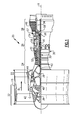
- FIG. 1 schematically illustrates a gas turbine engine 20.
- the gas turbine engine 20 is disclosed herein as a two-spool turbofan that generally incorporates a fan section 22, a compressor section 24, a combustor section 26 and a turbine section 28.
- Alternative engines might include an augmenter section (not shown) among other systems or features.
- the fan section 22 drives air along a bypass flow path B in a bypass duct defined within a nacelle 15, while the compressor section 24 drives air along a core flow path C for compression and communication into the combustor section 26 then expansion through the turbine section 28.
- the exemplary engine 20 generally includes a low speed spool 30 and a high speed spool 32 mounted for rotation about an engine central longitudinal axis X relative to an engine static structure 36 via several bearing systems 38. It should be understood that various bearing systems 38 at various locations may alternatively or additionally be provided, and the location of bearing systems 38 may be varied as appropriate to the application.
- the low speed spool 30 generally includes an inner shaft 40 that interconnects a fan 42, a first (or low) pressure compressor 44 and a first (or low) pressure turbine 46.
- the inner shaft 40 is connected to the fan 42 through a speed change mechanism, which in exemplary gas turbine engine 20 is illustrated as a geared architecture 48 to drive the fan 42 at a lower speed than the low speed spool 30.
- the high speed spool 32 includes an outer shaft 50 that interconnects a second (or high) pressure compressor 52 and a second (or high) pressure turbine 54.
- a combustor 56 is arranged in exemplary gas turbine 20 between the high pressure compressor 52 and the high pressure turbine 54.
- a mid-turbine frame 57 of the engine static structure 36 is arranged generally between the high pressure turbine 54 and the low pressure turbine 46.
- the mid-turbine frame 57 further supports bearing systems 38 in the turbine section 28.
- the inner shaft 40 and the outer shaft 50 are concentric and rotate via bearing systems 38 about the engine central longitudinal axis X which is collinear with their longitudinal axes.
- the core airflow is compressed by the low pressure compressor 44 then the high pressure compressor 52, mixed and burned with fuel in the combustor 56, then expanded over the high pressure turbine 54 and low pressure turbine 46.
- the mid-turbine frame 57 includes airfoils 59 which are in the core airflow path C.
- the turbines 46, 54 rotationally drive the respective low speed spool 30 and high speed spool 32 in response to the expansion.
- gear system 48 may be located aft of combustor section 26 or even aft of turbine section 28, and fan section 22 may be positioned forward or aft of the location of gear system 48.
- the engine 20 in one example is a high-bypass geared aircraft engine.
- the engine 20 bypass ratio is greater than about six (6), with an example embodiment being greater than about ten (10)
- the geared architecture 48 is an epicyclic gear train, such as a planetary gear system or other gear system, with a gear reduction ratio of greater than about 2.3
- the low pressure turbine 46 has a pressure ratio that is greater than about five.
- the engine 20 bypass ratio is greater than about ten (10:1)
- the fan diameter is significantly larger than that of the low pressure compressor 44
- the low pressure turbine 46 has a pressure ratio that is greater than about five 5:1.
- Low pressure turbine 46 pressure ratio is pressure measured prior to inlet of low pressure turbine 46 as related to the pressure at the outlet of the low pressure turbine 46 prior to an exhaust nozzle.
- the geared architecture 48 may be an epicycle gear train, such as a planetary gear system or other gear system, with a gear reduction ratio of greater than about 2.3:1. It should be understood, however, that the above parameters are only exemplary of one embodiment of a geared architecture engine and that the present invention is applicable to other gas turbine engines including direct drive turbofans.
- the fan section 22 of the engine 20 is designed for a particular flight condition -- typically cruise at about 0.8 Mach and about 35,000 feet (10,668 meters).
- the flight condition of 0.8 Mach and 35,000 ft (10,668 meters), with the engine at its best fuel consumption - also known as "bucket cruise Thrust Specific Fuel Consumption ('TSFC')" - is the industry standard parameter of lbm of fuel being burned divided by lbf of thrust the engine produces at that minimum point.
- "Low fan pressure ratio” is the pressure ratio across the fan blade alone, without a Fan Exit Guide Vane (“FEGV”) system.
- the low fan pressure ratio as disclosed herein according to one non-limiting embodiment is less than about 1.45.
- Low corrected fan tip speed is the actual fan tip speed in ft/sec divided by an industry standard temperature correction of [(Tram °R) / (518.7 °R)] 0.5 .
- the "Low corrected fan tip speed” as disclosed herein according to one non-limiting embodiment is less than about 1150 ft / second (350.5 meters/second).
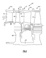
- first and second arrays 54a, 54c of circumferentially spaced fixed vanes 60, 62 are axially spaced apart from one another.
- a first stage array 54b of circumferentially spaced turbine blades 64, mounted to a rotor disk 68, is arranged axially between the first and second fixed vane arrays 54a, 54c.
- a second stage array 54d of circumferentially spaced turbine blades 66 is arranged aft of the second array 54c of fixed vanes 62.
- the turbine blades each include a tip 67 adjacent to a blade outer air seal 70 of a case structure 72.
- the first and second stage arrays 54a, 54c of turbine vanes and first and second stage arrays 54b, 54d of turbine blades are arranged within a core flow path C and are operatively connected to a spool 32.
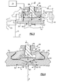
- a blade outer air seal assembly includes a circumferential array of blade outer air seal segments 70 that are supported relative to case structure 72, such as an outer case.
- the blade outer air seal 70 provides a seal relative to the tips 67 of the blade 64.
- a fluid source 74 is in fluid communication with a backside of the blade outer air seal 70 to provide cooling of components in the area and to passages within the blade outer air seal 70.
- Passages 76 communicate fluid from the fluid source 74 to a cavity 78 on the backside of the blade outer air seal 70.
- the fluid source 74 is bleed air from the compressor section. Forward and aft seals 77, 79 provide a seal between the blade outer air seal 70 and the case structure 72 to contain the cooling fluid.
- a mount block 80 secures adjacent ends 82 of the blade outer air seals 70 to the case structure 72 by a fastener assembly 84.
- the fastener assembly 84 includes a nut 86 and bolt 88.
- Each end 82 includes a groove 90 that receives a corresponding protrusion of the mount block 80.
- One or more shims 92 may be provided in the groove 90 between the end 82 and the mount block 80.
- a circumferential gap 83 is provided between the ends 82 to permit expansion and contraction of the blade outer air seals 70 during engine operation.
- edges 100 of the adjacent ends 82 are generally parallel to one another and extend radially with respect to the axis X.
- a tapered surface 98 adjoins the edge and groove 90 at each end 82. The tapered surfaces 98 of the adjoining ends 82 form an obtuse angle with respect to one another.
- a gap seal 94 engages the tapered surfaces 98 and obstructs the circumferential gap 83.
- the gap seal is wedge-shaped and includes sloped surfaces 102 that cooperate with the tapered surfaces 98.
- the tapered surfaces 98 and sloped surfaces 102 are in engagement with one another, as shown in Figures 4 and 5A .
- the sloped surfaces 102 adjoin one another at a first apex 104 that is aligned with the circumferential gap 83.
- the first apex 104 extends in a longitudinal direction of the body of the gap seal 94 and is arranged opposite a rectangular face 106.
- the sloped surfaces 98 and 102 are co-planar in the example.
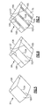
- the tapered surface of the gap seal 94 can include two separate, adjoining sloped surfaces, 102, 105, which meet at a second apex 107, providing a double wedge-shaped configuration.
- the sloped surfaces 102, 105 and second apex 107 are opposably symmetric (i.e., mirror images) about the axis of the first apex 104.
- the sloped surfaces 102, 105 of the gap seal 94 are not initially co-planar to the tapered surface 98. Contact between the gap seal 94 and the tapered surface 98 occurs between the second apex 107 and the tapered surface 98, as shown in Figure 6A . This contact arrangement is typically referred to as "line contact”. Generally the angular difference between the tapered surface 98 and sloped surfaces 102 and 104 are between 1 degree and 5 degrees, and preferably between 2 degrees and 4 degrees.
- a biasing member 96 is arranged radially between the fastening assembly 84 and the gap seal 94.
- the biasing member 96 is configured to urge the gap seal 94 radially inward toward the tapered surfaces 98.
- the biasing member 96 is a separate leaf spring, but alternatives to create a substantially radial biasing force would include wave springs, coil springs, and spring features integral to the mount block 80.
- the shims 92 are discrete from the biasing member 96.
- the gap seal 94 and tapered surface 98 are urged into contact via the biasing member 96.
- the sealing goes from intimate contact along the mating surfaces to a "line contact", depending upon the relative motion of the tapered surface 98 and the gap seal 94.
- the consistency of the sealing interface of the gap seal can vary, and will be sensitive to operational variation of the surfaces and tolerances of the gap seal 94, mount block 67, and blade outer air seal 82.
- gap seal 94 includes two sloped surfaces 102 and 105 intersecting at apex 107.
- the contact between the gap seal 94 and tapered surface 98 occurs as a "line contact" between the second apex 107 and the tapered surface 98.
- the relative contact between the tapered surface 98 and the gap seal 94 remains a "line contact" between the second apex 107 and the tapered surface 98.
- the consistency of the sealing interface is not dependent on surfaces remaining co-planar.
- the sealing interface is substantially insensitive to operational variation and tolerances of the gap seal 94, mount block 67, and blade outer air seal 82.
- the first apex 104 and the second apex 107 may be a sharp edge formed by the intersection of the sloped surfaces 102 and 105.
- a first radius 108 may be introduced that smoothly transitions the sloped surfaces 102
- a second radius 109 may be introduced that smoothly transitions the sloped surfaces 102 and 105.
- the radius maybe chosen such that there is generally no sharp edge at the first apex 104 and second apex 107.
- the gap seal 94 contacts the tapered surface 98 on the second radius 109 in a generally "line contact" manner, without a sharp edge, resulting in a reduced potential for damage to the second apex 107, as shown in Figure 7A .
- Articulation of the blade outer air seal 82 during engine operation is shown by the dashed lines in Figure 7B .
- the blade outer air seal segment 70 and the gap seal 94 have coefficient of thermal expansion that are generally between 2.5 ppm/°C and 4.5 ppm/°C.
- the case structure 72 typically has a coefficient of thermal expansion that is generally between 9 ppm/°C and 18 ppm/°C
- each of the blade outer air seals 70 and the gap seal 94 are a ceramic-based material.
- the blade outer air seal ends 82 expand and contract in a circumferential direction "a" increasing and decreasing the size of the circumferential gap 83.
- the biasing member 96 urges the gap seal 94 radially inward in a radially direction "r.”
- the blade outer air seal 82, gap seal 94, forward seal 77, aft seal 79 and case structure 72 expand and contract axially.
- the blade outer air seal 82 and gap seal 94 are exposed to high flowpath temperatures associated with flow C and with cooling source 74.
- the resulting steady-state operating temperature of the blade outer air seal 82 and gap seal 94 material is typically between the higher temperature flow C and the cooler temperature associated with the cooling source 74.
- the forward and aft seals, 77, 79, mount block 80 and case structure 72 are primarily exposed to cooling source 74.
- the resulting steady-state operating temperature of the forward and aft seals, 77, 79, mount block 80 and case structure 72 are generally equal to the cooling source 74.
- blade outer air seal 82 and gap seal 94 operate at substantially higher temperature than the forward and aft seals, 77, 79, mount block 80 and case structure 72. However, due to the relatively low coefficient of thermal expansion of the blade outer air seal 82 and gap seal 94, the axial growth of the blade outer air seal 82 and gap seal 94 is substantially less than the forward and aft seals, 77, 79, mount block 80 and case structure.
- the static pressure of the cooling source 74, within the first stage array 54b is desirably at the higher static pressure than the flow C at the first stage array 54b.
- Contact between the forward and aft seals 77, 79 and the blade outer air seal 82 and gap seal 94 is important to maintaining the pressure of cooling source 74.
- contact between the forward seal and aft seal 77, 79 is desirable to occur at a radial location R defined by the "line contact" region established by the second apex 107 and the tapered surface 98.
- the combination of "line contact" along apex 107, and the circumferential contact at radius R results in the efficient compartmentalization of the cooling source 74, within the first blade array 54b, and the improved ability to maintain static pressure within the first blade array 54a, with the minimal magnitude of cooling flow through the passages 76.
Landscapes
- Engineering & Computer Science (AREA)
- Mechanical Engineering (AREA)
- General Engineering & Computer Science (AREA)
- Turbine Rotor Nozzle Sealing (AREA)
Applications Claiming Priority (1)
| Application Number | Priority Date | Filing Date | Title |
|---|---|---|---|
| US201462053599P | 2014-09-22 | 2014-09-22 |
Publications (2)
| Publication Number | Publication Date |
|---|---|
| EP3000975A1 true EP3000975A1 (de) | 2016-03-30 |
| EP3000975B1 EP3000975B1 (de) | 2019-10-30 |
Family
ID=54148436
Family Applications (1)
| Application Number | Title | Priority Date | Filing Date |
|---|---|---|---|
| EP15185719.0A Active EP3000975B1 (de) | 2014-09-22 | 2015-09-17 | Äussere gasturbinenschaufel-luftabdichtungsanordnung |
Country Status (2)
| Country | Link |
|---|---|
| US (1) | US10443423B2 (de) |
| EP (1) | EP3000975B1 (de) |
Cited By (5)
| Publication number | Priority date | Publication date | Assignee | Title |
|---|---|---|---|---|
| EP3712382A3 (de) * | 2019-03-18 | 2020-09-30 | United Technologies Corporation | Äussere schaufelluftdichtung mit verschleissauskleidung |
| EP3767076A1 (de) * | 2019-07-19 | 2021-01-20 | Raytheon Technologies Corporation | Baugruppe mit schaufelaussenluftdichtung aus keramischem matrixverbundstoff |
| EP3767075A1 (de) * | 2019-07-19 | 2021-01-20 | Raytheon Technologies Corporation | Baugruppe mit schaufelaussenluftdichtung aus keramischem matrixverbundstoff |
| US11105214B2 (en) | 2019-07-19 | 2021-08-31 | Raytheon Technologies Corporation | CMC BOAS arrangement |
| US11248482B2 (en) | 2019-07-19 | 2022-02-15 | Raytheon Technologies Corporation | CMC BOAS arrangement |
Families Citing this family (14)
| Publication number | Priority date | Publication date | Assignee | Title |
|---|---|---|---|---|
| WO2015009384A1 (en) * | 2013-07-16 | 2015-01-22 | United Technologies Corporation | Gas turbine engine with ceramic panel |
| US10030530B2 (en) * | 2014-07-31 | 2018-07-24 | United Technologies Corporation | Reversible blade rotor seal |
| FR3034454B1 (fr) * | 2015-04-01 | 2018-04-20 | Safran Ceramics | Ensemble d'anneau de turbine avec liaison inter-secteurs |
| US10233763B2 (en) * | 2015-09-09 | 2019-03-19 | United Technologies Corporation | Seal assembly for turbine engine component |
| US10280799B2 (en) | 2016-06-10 | 2019-05-07 | United Technologies Corporation | Blade outer air seal assembly with positioning feature for gas turbine engine |
| US11021986B2 (en) * | 2018-03-20 | 2021-06-01 | Raytheon Technologies Corporation | Seal assembly for gas turbine engine |
| US10801351B2 (en) * | 2018-04-17 | 2020-10-13 | Raytheon Technologies Corporation | Seal assembly for gas turbine engine |
| US10689997B2 (en) * | 2018-04-17 | 2020-06-23 | Raytheon Technologies Corporation | Seal assembly for gas turbine engine |
| US11242764B2 (en) * | 2018-05-17 | 2022-02-08 | Raytheon Technologies Corporation | Seal assembly with baffle for gas turbine engine |
| US10704560B2 (en) | 2018-06-13 | 2020-07-07 | Rolls-Royce Corporation | Passive clearance control for a centrifugal impeller shroud |
| US11248480B2 (en) * | 2019-09-11 | 2022-02-15 | Raytheon Technologies Corporation | Intersegment seal for CMC boas assembly |
| US12012858B1 (en) * | 2023-04-28 | 2024-06-18 | Rtx Corporation | Failsafe blade outer airseal retention |
| US12345162B2 (en) | 2023-11-17 | 2025-07-01 | Rolls-Royce Corporation | Adjustable position impeller shroud for centrifugal compressors |
| US12345163B2 (en) | 2023-11-17 | 2025-07-01 | Rolls-Royce Corporation | Travel stop for a tip clearance control system |
Citations (6)
| Publication number | Priority date | Publication date | Assignee | Title |
|---|---|---|---|---|
| EP1270876A2 (de) * | 2001-06-18 | 2003-01-02 | General Electric Company | Federbelastete, abreibbare Dichtung für Turbomaschinen |
| US20030202876A1 (en) * | 2002-04-26 | 2003-10-30 | Christophe Jasklowski | Attachment of a ceramic shroud in a metal housing |
| US20050058540A1 (en) * | 2003-09-12 | 2005-03-17 | Siemens Westinghouse Power Corporation | Turbine engine sealing device |
| EP2090754A2 (de) * | 2008-02-18 | 2009-08-19 | United Technologies Corporation | Gasturbinenmotoren und Verfahren mit Schaufelspitzendichtungen |
| EP2546469A2 (de) * | 2011-07-15 | 2013-01-16 | United Technologies Corporation | Außendichtungsanordnung für eine Turbinenschaufel |
| US20140023480A1 (en) * | 2012-07-20 | 2014-01-23 | Michael G. McCaffrey | Radial position control of case supported structure |
Family Cites Families (8)
| Publication number | Priority date | Publication date | Assignee | Title |
|---|---|---|---|---|
| US4247248A (en) | 1978-12-20 | 1981-01-27 | United Technologies Corporation | Outer air seal support structure for gas turbine engine |
| US5333992A (en) * | 1993-02-05 | 1994-08-02 | United Technologies Corporation | Coolable outer air seal assembly for a gas turbine engine |
| US5374161A (en) | 1993-12-13 | 1994-12-20 | United Technologies Corporation | Blade outer air seal cooling enhanced with inter-segment film slot |
| GB0108398D0 (en) * | 2001-04-04 | 2001-05-23 | Siemens Ag | Seal element for sealing a gap and combustion turbine having a seal element |
| US6883807B2 (en) | 2002-09-13 | 2005-04-26 | Seimens Westinghouse Power Corporation | Multidirectional turbine shim seal |
| US20090096174A1 (en) | 2007-02-28 | 2009-04-16 | United Technologies Corporation | Blade outer air seal for a gas turbine engine |
| FR2913718B1 (fr) * | 2007-03-15 | 2009-06-05 | Snecma Propulsion Solide Sa | Ensemble d'anneau de turbine pour turbine a gaz |
| US8303247B2 (en) * | 2007-09-06 | 2012-11-06 | United Technologies Corporation | Blade outer air seal |
-
2015
- 2015-08-25 US US14/834,918 patent/US10443423B2/en active Active
- 2015-09-17 EP EP15185719.0A patent/EP3000975B1/de active Active
Patent Citations (6)
| Publication number | Priority date | Publication date | Assignee | Title |
|---|---|---|---|---|
| EP1270876A2 (de) * | 2001-06-18 | 2003-01-02 | General Electric Company | Federbelastete, abreibbare Dichtung für Turbomaschinen |
| US20030202876A1 (en) * | 2002-04-26 | 2003-10-30 | Christophe Jasklowski | Attachment of a ceramic shroud in a metal housing |
| US20050058540A1 (en) * | 2003-09-12 | 2005-03-17 | Siemens Westinghouse Power Corporation | Turbine engine sealing device |
| EP2090754A2 (de) * | 2008-02-18 | 2009-08-19 | United Technologies Corporation | Gasturbinenmotoren und Verfahren mit Schaufelspitzendichtungen |
| EP2546469A2 (de) * | 2011-07-15 | 2013-01-16 | United Technologies Corporation | Außendichtungsanordnung für eine Turbinenschaufel |
| US20140023480A1 (en) * | 2012-07-20 | 2014-01-23 | Michael G. McCaffrey | Radial position control of case supported structure |
Cited By (8)
| Publication number | Priority date | Publication date | Assignee | Title |
|---|---|---|---|---|
| EP3712382A3 (de) * | 2019-03-18 | 2020-09-30 | United Technologies Corporation | Äussere schaufelluftdichtung mit verschleissauskleidung |
| US10808564B2 (en) | 2019-03-18 | 2020-10-20 | Raytheon Technologies Corporatino | Wear liner for blade outer air seal |
| EP3767076A1 (de) * | 2019-07-19 | 2021-01-20 | Raytheon Technologies Corporation | Baugruppe mit schaufelaussenluftdichtung aus keramischem matrixverbundstoff |
| EP3767075A1 (de) * | 2019-07-19 | 2021-01-20 | Raytheon Technologies Corporation | Baugruppe mit schaufelaussenluftdichtung aus keramischem matrixverbundstoff |
| US11073038B2 (en) | 2019-07-19 | 2021-07-27 | Raytheon Technologies Corporation | CMC BOAS arrangement |
| US11073037B2 (en) | 2019-07-19 | 2021-07-27 | Raytheon Technologies Corporation | CMC BOAS arrangement |
| US11105214B2 (en) | 2019-07-19 | 2021-08-31 | Raytheon Technologies Corporation | CMC BOAS arrangement |
| US11248482B2 (en) | 2019-07-19 | 2022-02-15 | Raytheon Technologies Corporation | CMC BOAS arrangement |
Also Published As
| Publication number | Publication date |
|---|---|
| US10443423B2 (en) | 2019-10-15 |
| US20160084101A1 (en) | 2016-03-24 |
| EP3000975B1 (de) | 2019-10-30 |
Similar Documents
| Publication | Publication Date | Title |
|---|---|---|
| EP3000975B1 (de) | Äussere gasturbinenschaufel-luftabdichtungsanordnung | |
| EP3543469B1 (de) | Äussere laufschaufelluftdichtungsanordnung mit federdichtung | |
| EP3734018B1 (de) | Dichtung für ein gasturbinentriebwerks-bauteil und zugehöriges verfahren | |
| US10890079B2 (en) | Gas turbine engine arc segments with arced walls | |
| EP3102794B1 (de) | Halterung einer äusseren statordichtung für eine turbinenschaufel | |
| US10808562B2 (en) | Seal assembly for turbine engine component | |
| EP3102810B1 (de) | Umlaufende axiale segmentierte muldendichtung einer gasturbine | |
| EP3000967A2 (de) | Gasturbinenmotor-schaufelschlitz-hitzeschild | |
| US20210062667A1 (en) | Seal arrangement for turbine engine component | |
| EP3620615A1 (de) | Cmc-boas-axialhalteklemme | |
| US10301956B2 (en) | Seal assembly for sealing an axial gap between components | |
| EP3428408B1 (de) | Einsatzelement am ende einer verstellbaren schaufel in einem gasturbinentriebwerk | |
| EP2993303A1 (de) | Gasturbinenmotorkomponente mit filmkühlloch mit tasche | |
| US20160169020A1 (en) | Gas turbine engine non-rotating structure wedge seal | |
| US10001023B2 (en) | Grooved seal arrangement for turbine engine | |
| EP4183978A1 (de) | Scheibenbohrungsabdichtungen für gasturbinentriebwerke | |
| US10030530B2 (en) | Reversible blade rotor seal | |
| EP3760836B1 (de) | Doppelkammer deckband und haltevorrichtung | |
| US9810087B2 (en) | Reversible blade rotor seal with protrusions |
Legal Events
| Date | Code | Title | Description |
|---|---|---|---|
| PUAI | Public reference made under article 153(3) epc to a published international application that has entered the european phase |
Free format text: ORIGINAL CODE: 0009012 |
|
| AK | Designated contracting states |
Kind code of ref document: A1 Designated state(s): AL AT BE BG CH CY CZ DE DK EE ES FI FR GB GR HR HU IE IS IT LI LT LU LV MC MK MT NL NO PL PT RO RS SE SI SK SM TR |
|
| AX | Request for extension of the european patent |
Extension state: BA ME |
|
| RAP1 | Party data changed (applicant data changed or rights of an application transferred) |
Owner name: UNITED TECHNOLOGIES CORPORATION |
|
| 17P | Request for examination filed |
Effective date: 20160930 |
|
| RBV | Designated contracting states (corrected) |
Designated state(s): AL AT BE BG CH CY CZ DE DK EE ES FI FR GB GR HR HU IE IS IT LI LT LU LV MC MK MT NL NO PL PT RO RS SE SI SK SM TR |
|
| GRAP | Despatch of communication of intention to grant a patent |
Free format text: ORIGINAL CODE: EPIDOSNIGR1 |
|
| STAA | Information on the status of an ep patent application or granted ep patent |
Free format text: STATUS: GRANT OF PATENT IS INTENDED |
|
| INTG | Intention to grant announced |
Effective date: 20181129 |
|
| GRAJ | Information related to disapproval of communication of intention to grant by the applicant or resumption of examination proceedings by the epo deleted |
Free format text: ORIGINAL CODE: EPIDOSDIGR1 |
|
| STAA | Information on the status of an ep patent application or granted ep patent |
Free format text: STATUS: REQUEST FOR EXAMINATION WAS MADE |
|
| GRAJ | Information related to disapproval of communication of intention to grant by the applicant or resumption of examination proceedings by the epo deleted |
Free format text: ORIGINAL CODE: EPIDOSDIGR1 |
|
| STAA | Information on the status of an ep patent application or granted ep patent |
Free format text: STATUS: GRANT OF PATENT IS INTENDED |
|
| GRAP | Despatch of communication of intention to grant a patent |
Free format text: ORIGINAL CODE: EPIDOSNIGR1 |
|
| INTC | Intention to grant announced (deleted) | ||
| INTG | Intention to grant announced |
Effective date: 20190516 |
|
| GRAS | Grant fee paid |
Free format text: ORIGINAL CODE: EPIDOSNIGR3 |
|
| GRAA | (expected) grant |
Free format text: ORIGINAL CODE: 0009210 |
|
| STAA | Information on the status of an ep patent application or granted ep patent |
Free format text: STATUS: THE PATENT HAS BEEN GRANTED |
|
| AK | Designated contracting states |
Kind code of ref document: B1 Designated state(s): AL AT BE BG CH CY CZ DE DK EE ES FI FR GB GR HR HU IE IS IT LI LT LU LV MC MK MT NL NO PL PT RO RS SE SI SK SM TR |
|
| REG | Reference to a national code |
Ref country code: GB Ref legal event code: FG4D |
|
| REG | Reference to a national code |
Ref country code: CH Ref legal event code: EP |
|
| REG | Reference to a national code |
Ref country code: AT Ref legal event code: REF Ref document number: 1196350 Country of ref document: AT Kind code of ref document: T Effective date: 20191115 |
|
| REG | Reference to a national code |
Ref country code: DE Ref legal event code: R096 Ref document number: 602015040606 Country of ref document: DE |
|
| REG | Reference to a national code |
Ref country code: IE Ref legal event code: FG4D |
|
| REG | Reference to a national code |
Ref country code: LT Ref legal event code: MG4D |
|
| PG25 | Lapsed in a contracting state [announced via postgrant information from national office to epo] |
Ref country code: LV Free format text: LAPSE BECAUSE OF FAILURE TO SUBMIT A TRANSLATION OF THE DESCRIPTION OR TO PAY THE FEE WITHIN THE PRESCRIBED TIME-LIMIT Effective date: 20191030 Ref country code: SE Free format text: LAPSE BECAUSE OF FAILURE TO SUBMIT A TRANSLATION OF THE DESCRIPTION OR TO PAY THE FEE WITHIN THE PRESCRIBED TIME-LIMIT Effective date: 20191030 Ref country code: PT Free format text: LAPSE BECAUSE OF FAILURE TO SUBMIT A TRANSLATION OF THE DESCRIPTION OR TO PAY THE FEE WITHIN THE PRESCRIBED TIME-LIMIT Effective date: 20200302 Ref country code: FI Free format text: LAPSE BECAUSE OF FAILURE TO SUBMIT A TRANSLATION OF THE DESCRIPTION OR TO PAY THE FEE WITHIN THE PRESCRIBED TIME-LIMIT Effective date: 20191030 Ref country code: BG Free format text: LAPSE BECAUSE OF FAILURE TO SUBMIT A TRANSLATION OF THE DESCRIPTION OR TO PAY THE FEE WITHIN THE PRESCRIBED TIME-LIMIT Effective date: 20200130 Ref country code: NO Free format text: LAPSE BECAUSE OF FAILURE TO SUBMIT A TRANSLATION OF THE DESCRIPTION OR TO PAY THE FEE WITHIN THE PRESCRIBED TIME-LIMIT Effective date: 20200130 Ref country code: GR Free format text: LAPSE BECAUSE OF FAILURE TO SUBMIT A TRANSLATION OF THE DESCRIPTION OR TO PAY THE FEE WITHIN THE PRESCRIBED TIME-LIMIT Effective date: 20200131 Ref country code: NL Free format text: LAPSE BECAUSE OF FAILURE TO SUBMIT A TRANSLATION OF THE DESCRIPTION OR TO PAY THE FEE WITHIN THE PRESCRIBED TIME-LIMIT Effective date: 20191030 Ref country code: PL Free format text: LAPSE BECAUSE OF FAILURE TO SUBMIT A TRANSLATION OF THE DESCRIPTION OR TO PAY THE FEE WITHIN THE PRESCRIBED TIME-LIMIT Effective date: 20191030 Ref country code: LT Free format text: LAPSE BECAUSE OF FAILURE TO SUBMIT A TRANSLATION OF THE DESCRIPTION OR TO PAY THE FEE WITHIN THE PRESCRIBED TIME-LIMIT Effective date: 20191030 Ref country code: ES Free format text: LAPSE BECAUSE OF FAILURE TO SUBMIT A TRANSLATION OF THE DESCRIPTION OR TO PAY THE FEE WITHIN THE PRESCRIBED TIME-LIMIT Effective date: 20191030 |
|
| REG | Reference to a national code |
Ref country code: NL Ref legal event code: MP Effective date: 20191030 |
|
| PG25 | Lapsed in a contracting state [announced via postgrant information from national office to epo] |
Ref country code: HR Free format text: LAPSE BECAUSE OF FAILURE TO SUBMIT A TRANSLATION OF THE DESCRIPTION OR TO PAY THE FEE WITHIN THE PRESCRIBED TIME-LIMIT Effective date: 20191030 Ref country code: IS Free format text: LAPSE BECAUSE OF FAILURE TO SUBMIT A TRANSLATION OF THE DESCRIPTION OR TO PAY THE FEE WITHIN THE PRESCRIBED TIME-LIMIT Effective date: 20200229 Ref country code: RS Free format text: LAPSE BECAUSE OF FAILURE TO SUBMIT A TRANSLATION OF THE DESCRIPTION OR TO PAY THE FEE WITHIN THE PRESCRIBED TIME-LIMIT Effective date: 20191030 |
|
| PG25 | Lapsed in a contracting state [announced via postgrant information from national office to epo] |
Ref country code: AL Free format text: LAPSE BECAUSE OF FAILURE TO SUBMIT A TRANSLATION OF THE DESCRIPTION OR TO PAY THE FEE WITHIN THE PRESCRIBED TIME-LIMIT Effective date: 20191030 |
|
| PG25 | Lapsed in a contracting state [announced via postgrant information from national office to epo] |
Ref country code: EE Free format text: LAPSE BECAUSE OF FAILURE TO SUBMIT A TRANSLATION OF THE DESCRIPTION OR TO PAY THE FEE WITHIN THE PRESCRIBED TIME-LIMIT Effective date: 20191030 Ref country code: RO Free format text: LAPSE BECAUSE OF FAILURE TO SUBMIT A TRANSLATION OF THE DESCRIPTION OR TO PAY THE FEE WITHIN THE PRESCRIBED TIME-LIMIT Effective date: 20191030 Ref country code: CZ Free format text: LAPSE BECAUSE OF FAILURE TO SUBMIT A TRANSLATION OF THE DESCRIPTION OR TO PAY THE FEE WITHIN THE PRESCRIBED TIME-LIMIT Effective date: 20191030 Ref country code: DK Free format text: LAPSE BECAUSE OF FAILURE TO SUBMIT A TRANSLATION OF THE DESCRIPTION OR TO PAY THE FEE WITHIN THE PRESCRIBED TIME-LIMIT Effective date: 20191030 |
|
| REG | Reference to a national code |
Ref country code: DE Ref legal event code: R097 Ref document number: 602015040606 Country of ref document: DE |
|
| REG | Reference to a national code |
Ref country code: AT Ref legal event code: MK05 Ref document number: 1196350 Country of ref document: AT Kind code of ref document: T Effective date: 20191030 |
|
| PG25 | Lapsed in a contracting state [announced via postgrant information from national office to epo] |
Ref country code: IT Free format text: LAPSE BECAUSE OF FAILURE TO SUBMIT A TRANSLATION OF THE DESCRIPTION OR TO PAY THE FEE WITHIN THE PRESCRIBED TIME-LIMIT Effective date: 20191030 Ref country code: SM Free format text: LAPSE BECAUSE OF FAILURE TO SUBMIT A TRANSLATION OF THE DESCRIPTION OR TO PAY THE FEE WITHIN THE PRESCRIBED TIME-LIMIT Effective date: 20191030 Ref country code: SK Free format text: LAPSE BECAUSE OF FAILURE TO SUBMIT A TRANSLATION OF THE DESCRIPTION OR TO PAY THE FEE WITHIN THE PRESCRIBED TIME-LIMIT Effective date: 20191030 |
|
| PLBE | No opposition filed within time limit |
Free format text: ORIGINAL CODE: 0009261 |
|
| STAA | Information on the status of an ep patent application or granted ep patent |
Free format text: STATUS: NO OPPOSITION FILED WITHIN TIME LIMIT |
|
| 26N | No opposition filed |
Effective date: 20200731 |
|
| PG25 | Lapsed in a contracting state [announced via postgrant information from national office to epo] |
Ref country code: SI Free format text: LAPSE BECAUSE OF FAILURE TO SUBMIT A TRANSLATION OF THE DESCRIPTION OR TO PAY THE FEE WITHIN THE PRESCRIBED TIME-LIMIT Effective date: 20191030 Ref country code: AT Free format text: LAPSE BECAUSE OF FAILURE TO SUBMIT A TRANSLATION OF THE DESCRIPTION OR TO PAY THE FEE WITHIN THE PRESCRIBED TIME-LIMIT Effective date: 20191030 |
|
| PG25 | Lapsed in a contracting state [announced via postgrant information from national office to epo] |
Ref country code: MC Free format text: LAPSE BECAUSE OF FAILURE TO SUBMIT A TRANSLATION OF THE DESCRIPTION OR TO PAY THE FEE WITHIN THE PRESCRIBED TIME-LIMIT Effective date: 20191030 |
|
| REG | Reference to a national code |
Ref country code: CH Ref legal event code: PL |
|
| REG | Reference to a national code |
Ref country code: BE Ref legal event code: MM Effective date: 20200930 |
|
| PG25 | Lapsed in a contracting state [announced via postgrant information from national office to epo] |
Ref country code: LU Free format text: LAPSE BECAUSE OF NON-PAYMENT OF DUE FEES Effective date: 20200917 |
|
| PG25 | Lapsed in a contracting state [announced via postgrant information from national office to epo] |
Ref country code: LI Free format text: LAPSE BECAUSE OF NON-PAYMENT OF DUE FEES Effective date: 20200930 Ref country code: IE Free format text: LAPSE BECAUSE OF NON-PAYMENT OF DUE FEES Effective date: 20200917 Ref country code: BE Free format text: LAPSE BECAUSE OF NON-PAYMENT OF DUE FEES Effective date: 20200930 Ref country code: CH Free format text: LAPSE BECAUSE OF NON-PAYMENT OF DUE FEES Effective date: 20200930 |
|
| PG25 | Lapsed in a contracting state [announced via postgrant information from national office to epo] |
Ref country code: TR Free format text: LAPSE BECAUSE OF FAILURE TO SUBMIT A TRANSLATION OF THE DESCRIPTION OR TO PAY THE FEE WITHIN THE PRESCRIBED TIME-LIMIT Effective date: 20191030 Ref country code: MT Free format text: LAPSE BECAUSE OF FAILURE TO SUBMIT A TRANSLATION OF THE DESCRIPTION OR TO PAY THE FEE WITHIN THE PRESCRIBED TIME-LIMIT Effective date: 20191030 Ref country code: CY Free format text: LAPSE BECAUSE OF FAILURE TO SUBMIT A TRANSLATION OF THE DESCRIPTION OR TO PAY THE FEE WITHIN THE PRESCRIBED TIME-LIMIT Effective date: 20191030 |
|
| PG25 | Lapsed in a contracting state [announced via postgrant information from national office to epo] |
Ref country code: MK Free format text: LAPSE BECAUSE OF FAILURE TO SUBMIT A TRANSLATION OF THE DESCRIPTION OR TO PAY THE FEE WITHIN THE PRESCRIBED TIME-LIMIT Effective date: 20191030 |
|
| REG | Reference to a national code |
Ref country code: DE Ref legal event code: R081 Ref document number: 602015040606 Country of ref document: DE Owner name: RAYTHEON TECHNOLOGIES CORPORATION (N.D.GES.D.S, US Free format text: FORMER OWNER: UNITED TECHNOLOGIES CORPORATION, FARMINGTON, CONN., US Ref country code: DE Ref legal event code: R081 Ref document number: 602015040606 Country of ref document: DE Owner name: RTX CORPORATION (N.D.GES.D. STAATES DELAWARE),, US Free format text: FORMER OWNER: UNITED TECHNOLOGIES CORPORATION, FARMINGTON, CONN., US |
|
| P01 | Opt-out of the competence of the unified patent court (upc) registered |
Effective date: 20230520 |
|
| PGFP | Annual fee paid to national office [announced via postgrant information from national office to epo] |
Ref country code: DE Payment date: 20250820 Year of fee payment: 11 |
|
| PGFP | Annual fee paid to national office [announced via postgrant information from national office to epo] |
Ref country code: GB Payment date: 20250820 Year of fee payment: 11 |
|
| PGFP | Annual fee paid to national office [announced via postgrant information from national office to epo] |
Ref country code: FR Payment date: 20250820 Year of fee payment: 11 |
|
| REG | Reference to a national code |
Ref country code: DE Ref legal event code: R081 Ref document number: 602015040606 Country of ref document: DE Owner name: RTX CORPORATION (N.D.GES.D. STAATES DELAWARE),, US Free format text: FORMER OWNER: RAYTHEON TECHNOLOGIES CORPORATION (N.D.GES.D.STAATES DELAWARE), ARLINGTON, VA, US |