EP3001104B1 - Kraftwerk mit fossilem brennstoff und betriebsverfahren für ein kraftwerk mit fossilem brennstoff - Google Patents
Kraftwerk mit fossilem brennstoff und betriebsverfahren für ein kraftwerk mit fossilem brennstoff Download PDFInfo
- Publication number
- EP3001104B1 EP3001104B1 EP14801816.1A EP14801816A EP3001104B1 EP 3001104 B1 EP3001104 B1 EP 3001104B1 EP 14801816 A EP14801816 A EP 14801816A EP 3001104 B1 EP3001104 B1 EP 3001104B1
- Authority
- EP
- European Patent Office
- Prior art keywords
- feed
- exhaust gas
- water
- temperature
- economizer
- Prior art date
- Legal status (The legal status is an assumption and is not a legal conclusion. Google has not performed a legal analysis and makes no representation as to the accuracy of the status listed.)
- Active
Links
Images

Classifications
-
- F—MECHANICAL ENGINEERING; LIGHTING; HEATING; WEAPONS; BLASTING
- F22—STEAM GENERATION
- F22D—PREHEATING, OR ACCUMULATING PREHEATED, FEED-WATER FOR STEAM GENERATION; FEED-WATER SUPPLY FOR STEAM GENERATION; CONTROLLING WATER LEVEL FOR STEAM GENERATION; AUXILIARY DEVICES FOR PROMOTING WATER CIRCULATION WITHIN STEAM BOILERS
- F22D1/00—Feed-water heaters, i.e. economisers or like preheaters
- F22D1/36—Water and air preheating systems
- F22D1/38—Constructional features of water and air preheating systems
-
- F—MECHANICAL ENGINEERING; LIGHTING; HEATING; WEAPONS; BLASTING
- F23—COMBUSTION APPARATUS; COMBUSTION PROCESSES
- F23J—REMOVAL OR TREATMENT OF COMBUSTION PRODUCTS OR COMBUSTION RESIDUES; FLUES
- F23J15/00—Arrangements of devices for treating smoke or fumes
- F23J15/02—Arrangements of devices for treating smoke or fumes of purifiers, e.g. for removing noxious material
-
- F—MECHANICAL ENGINEERING; LIGHTING; HEATING; WEAPONS; BLASTING
- F01—MACHINES OR ENGINES IN GENERAL; ENGINE PLANTS IN GENERAL; STEAM ENGINES
- F01K—STEAM ENGINE PLANTS; STEAM ACCUMULATORS; ENGINE PLANTS NOT OTHERWISE PROVIDED FOR; ENGINES USING SPECIAL WORKING FLUIDS OR CYCLES
- F01K7/00—Steam engine plants characterised by the use of specific types of engine; Plants or engines characterised by their use of special steam systems, cycles or processes; Control means specially adapted for such systems, cycles or processes; Use of withdrawn or exhaust steam for feed-water heating
- F01K7/16—Steam engine plants characterised by the use of specific types of engine; Plants or engines characterised by their use of special steam systems, cycles or processes; Control means specially adapted for such systems, cycles or processes; Use of withdrawn or exhaust steam for feed-water heating the engines being only of turbine type
- F01K7/22—Steam engine plants characterised by the use of specific types of engine; Plants or engines characterised by their use of special steam systems, cycles or processes; Control means specially adapted for such systems, cycles or processes; Use of withdrawn or exhaust steam for feed-water heating the engines being only of turbine type the turbines having inter-stage steam heating
-
- F—MECHANICAL ENGINEERING; LIGHTING; HEATING; WEAPONS; BLASTING
- F01—MACHINES OR ENGINES IN GENERAL; ENGINE PLANTS IN GENERAL; STEAM ENGINES
- F01K—STEAM ENGINE PLANTS; STEAM ACCUMULATORS; ENGINE PLANTS NOT OTHERWISE PROVIDED FOR; ENGINES USING SPECIAL WORKING FLUIDS OR CYCLES
- F01K7/00—Steam engine plants characterised by the use of specific types of engine; Plants or engines characterised by their use of special steam systems, cycles or processes; Control means specially adapted for such systems, cycles or processes; Use of withdrawn or exhaust steam for feed-water heating
- F01K7/34—Steam engine plants characterised by the use of specific types of engine; Plants or engines characterised by their use of special steam systems, cycles or processes; Control means specially adapted for such systems, cycles or processes; Use of withdrawn or exhaust steam for feed-water heating the engines being of extraction or non-condensing type; Use of steam for feed-water heating
- F01K7/40—Use of two or more feed-water heaters in series
-
- F—MECHANICAL ENGINEERING; LIGHTING; HEATING; WEAPONS; BLASTING
- F22—STEAM GENERATION
- F22D—PREHEATING, OR ACCUMULATING PREHEATED, FEED-WATER FOR STEAM GENERATION; FEED-WATER SUPPLY FOR STEAM GENERATION; CONTROLLING WATER LEVEL FOR STEAM GENERATION; AUXILIARY DEVICES FOR PROMOTING WATER CIRCULATION WITHIN STEAM BOILERS
- F22D1/00—Feed-water heaters, i.e. economisers or like preheaters
- F22D1/02—Feed-water heaters, i.e. economisers or like preheaters with water tubes arranged in the boiler furnaces, fire tubes or flue ways
-
- F—MECHANICAL ENGINEERING; LIGHTING; HEATING; WEAPONS; BLASTING
- F22—STEAM GENERATION
- F22D—PREHEATING, OR ACCUMULATING PREHEATED, FEED-WATER FOR STEAM GENERATION; FEED-WATER SUPPLY FOR STEAM GENERATION; CONTROLLING WATER LEVEL FOR STEAM GENERATION; AUXILIARY DEVICES FOR PROMOTING WATER CIRCULATION WITHIN STEAM BOILERS
- F22D1/00—Feed-water heaters, i.e. economisers or like preheaters
- F22D1/32—Feed-water heaters, i.e. economisers or like preheaters arranged to be heated by steam, e.g. bled from turbines
-
- F—MECHANICAL ENGINEERING; LIGHTING; HEATING; WEAPONS; BLASTING
- F22—STEAM GENERATION
- F22D—PREHEATING, OR ACCUMULATING PREHEATED, FEED-WATER FOR STEAM GENERATION; FEED-WATER SUPPLY FOR STEAM GENERATION; CONTROLLING WATER LEVEL FOR STEAM GENERATION; AUXILIARY DEVICES FOR PROMOTING WATER CIRCULATION WITHIN STEAM BOILERS
- F22D1/00—Feed-water heaters, i.e. economisers or like preheaters
- F22D1/32—Feed-water heaters, i.e. economisers or like preheaters arranged to be heated by steam, e.g. bled from turbines
- F22D1/34—Feed-water heaters, i.e. economisers or like preheaters arranged to be heated by steam, e.g. bled from turbines and returning condensate to boiler with main feed supply
-
- F—MECHANICAL ENGINEERING; LIGHTING; HEATING; WEAPONS; BLASTING
- F23—COMBUSTION APPARATUS; COMBUSTION PROCESSES
- F23J—REMOVAL OR TREATMENT OF COMBUSTION PRODUCTS OR COMBUSTION RESIDUES; FLUES
- F23J15/00—Arrangements of devices for treating smoke or fumes
-
- F—MECHANICAL ENGINEERING; LIGHTING; HEATING; WEAPONS; BLASTING
- F23—COMBUSTION APPARATUS; COMBUSTION PROCESSES
- F23J—REMOVAL OR TREATMENT OF COMBUSTION PRODUCTS OR COMBUSTION RESIDUES; FLUES
- F23J15/00—Arrangements of devices for treating smoke or fumes
- F23J15/06—Arrangements of devices for treating smoke or fumes of coolers
-
- F—MECHANICAL ENGINEERING; LIGHTING; HEATING; WEAPONS; BLASTING
- F23—COMBUSTION APPARATUS; COMBUSTION PROCESSES
- F23L—SUPPLYING AIR OR NON-COMBUSTIBLE LIQUIDS OR GASES TO COMBUSTION APPARATUS IN GENERAL ; VALVES OR DAMPERS SPECIALLY ADAPTED FOR CONTROLLING AIR SUPPLY OR DRAUGHT IN COMBUSTION APPARATUS; INDUCING DRAUGHT IN COMBUSTION APPARATUS; TOPS FOR CHIMNEYS OR VENTILATING SHAFTS; TERMINALS FOR FLUES
- F23L11/00—Arrangements of valves or dampers after the fire
-
- F—MECHANICAL ENGINEERING; LIGHTING; HEATING; WEAPONS; BLASTING
- F23—COMBUSTION APPARATUS; COMBUSTION PROCESSES
- F23L—SUPPLYING AIR OR NON-COMBUSTIBLE LIQUIDS OR GASES TO COMBUSTION APPARATUS IN GENERAL ; VALVES OR DAMPERS SPECIALLY ADAPTED FOR CONTROLLING AIR SUPPLY OR DRAUGHT IN COMBUSTION APPARATUS; INDUCING DRAUGHT IN COMBUSTION APPARATUS; TOPS FOR CHIMNEYS OR VENTILATING SHAFTS; TERMINALS FOR FLUES
- F23L15/00—Heating of air supplied for combustion
- F23L15/02—Arrangements of regenerators
-
- F—MECHANICAL ENGINEERING; LIGHTING; HEATING; WEAPONS; BLASTING
- F23—COMBUSTION APPARATUS; COMBUSTION PROCESSES
- F23J—REMOVAL OR TREATMENT OF COMBUSTION PRODUCTS OR COMBUSTION RESIDUES; FLUES
- F23J2215/00—Preventing emissions
- F23J2215/10—Nitrogen; Compounds thereof
-
- F—MECHANICAL ENGINEERING; LIGHTING; HEATING; WEAPONS; BLASTING
- F23—COMBUSTION APPARATUS; COMBUSTION PROCESSES
- F23J—REMOVAL OR TREATMENT OF COMBUSTION PRODUCTS OR COMBUSTION RESIDUES; FLUES
- F23J2219/00—Treatment devices
- F23J2219/10—Catalytic reduction devices
-
- Y—GENERAL TAGGING OF NEW TECHNOLOGICAL DEVELOPMENTS; GENERAL TAGGING OF CROSS-SECTIONAL TECHNOLOGIES SPANNING OVER SEVERAL SECTIONS OF THE IPC; TECHNICAL SUBJECTS COVERED BY FORMER USPC CROSS-REFERENCE ART COLLECTIONS [XRACs] AND DIGESTS
- Y02—TECHNOLOGIES OR APPLICATIONS FOR MITIGATION OR ADAPTATION AGAINST CLIMATE CHANGE
- Y02E—REDUCTION OF GREENHOUSE GAS [GHG] EMISSIONS, RELATED TO ENERGY GENERATION, TRANSMISSION OR DISTRIBUTION
- Y02E20/00—Combustion technologies with mitigation potential
- Y02E20/34—Indirect CO2mitigation, i.e. by acting on non CO2directly related matters of the process, e.g. pre-heating or heat recovery
Definitions
- the present invention relates to a thermal power plant and a method of operating the thermal power plant.
- US 2011/094228 A1 discloses a method of increasing the performance, i.e., the thermal efficiency and/or power of a carbonaceous fuel combusting boiler system.
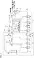
- FIG. 3 is the system diagram showing an example of a configuration of a general thermal power plant described in Non Patent Literature 1 detailed below.
- a general thermal power plant is generally constructed from the boiler 2; the steam system 3; the condensate system 44; and the feed-water system 4.
- the boiler 2 generates the combustion gas and combustion heat by combusting fuel such as coal, oil, or the like; and generates steam by increasing a temperature of feed-water by using the combustion heat.
- the steam system 3 has multiple steam turbines 5 and the condenser 6. Each of the steam turbines 5 is driven by the steam generated by the boiler 2.
- the steam exhausted from the steam turbines 5 enters into the condenser 6 to be steam condensate.
- the steam condensate in the condenser 6 is returned back to the boiler 2 through the condensate system 44 and feed-water system 4.
- the condensate system 44 has the condensate pump 7 for supplying the steam condensate, the low-pressure feed-water heater 8 constituted from multiple heat exchangers, and the deaerator 9.
- the feed-water system 4 has the high-pressure feed-water heater 10 constituted from the boiler feed-water pump 45 and multiple heat exchangers.
- FIG. 4 is an enlarged view of the region P shown in FIG. 3 and indicates an enlarged view of the configuration around the boiler in a conventional coal-fired power plant as an example of a general thermal power plant.
- the conventional coal-fired power plant 101 has: the boiler 102; the steam system 103; the feed-water system 104; the exhaust gas system 111; the primary air system 112; and the secondary air system 113.
- the exhaust gas system 111 has the catalytic NOx removal equipment 114; the regenerative air preheater 115; the dust collector 116; the induced draft fan 117; the sulfur removal equipment 118; and the chimney 119.
- This exhaust gas system 111 is the flue channeling the combustion gas exhausted from the boiler 102 as the exhaust gas to the chimney 119.
- the exhaust gas exhausted from the boiler 102 is sent to the regenerative air preheater 115 after passage through the NOx removal equipment 114.
- the exhausted gas sent to the air preheater 115 passes through the dust collector 116; the induced draft fan 117; and the sulfur removal equipment 118, and is discharged into the atmosphere eventually.
- the primary air system 112 has the primary air fan120; the hot air damper 121; the bypass duct 122 to bypass the air preheater 115; the cold air damper 123 provided to the bypass duct 122; and the coal pulverizer 124.
- the primary air is produced by mixing the hot air, which is heated by heat exchanging with the exhaust gas from the boiler 102 in the air preheater 115, and the cold air, which provided from the bypass duct 122 bypassing the air preheater 115, by controlling each of openings of the hot air damper 121 and the cold air damper 123. Because of this, the air amount of the primary air is adjusted to the required amount for transporting the pulverized coal.
- temperature of the primary air at the inlet of the coal pulverizer 124 is adjusted to the required temperature.
- the primary air is introduced into the coal pulverizer 124.
- the primary air introduced into the coal pulverizer 124 evaporates the moisture in the pulverized coal by using its potential heat; and transfers the dried pulverized coal to the pulverized coal burner provided to the boiler 102 to have the pulverized coal to be combusted.
- the fuel coal is supplied to the coal pulverizer 124 and pulverized to a predetermined grain size.
- the secondary air system 113 has the forced draft fan125.
- the secondary air is introduced into the air preheater 115 and heated by heat exchanging with the exhaust gas from the boiler 102. Then, the secondary air is introduced into the boiler 102 as the air for combustion by the pulverized coal burner and the air for the two staged combustion.
- the feed-water system 104 has the deaerator 109; the boiler feed-water pump 145; the high-pressure feed-water heater 110; and the economizer 136.
- the extraction system 129, and the extraction system 130 are provided, respectively.
- the extraction steam from the intermediate-pressure steam turbine 1051 flows in both of the extraction systems 129, 130.
- the steam extraction systems 131, 132 are provided between the high-pressure steam turbine 105H and the high-pressure feed-water heater 110.
- the extraction steam from the high-pressure steam turbine 105H flows in both of the extraction systems 131, 132.
- the drain pipes 133-135 are piping in which drain from the high-pressure feed-water heater flows.
- the high-pressure feed-water heater 110 is consisted from multiple heat exchangers. They are referred as the first high-pressure feed-water heater 126; the second high-pressure feed-water heater 127; and the third high-pressure feed-water heater 128 based on their locations from the deaerator 109 for the sake of simplicity. Feed-water heated in the high-pressure feed-water heater 110 is sent to the economizer 136 in the boiler 102.
- Each of heat exchangers of the high-pressure feed-water heater 110 heats feed-water by using the steam extracted from the intermediate-pressure steam turbine 1051 and the high-pressure steam turbine 105H.
- the extraction system 130 sends the extraction steam to the first high-pressure feed-water heater 126; the extraction system 131 sends the extraction steam to the second high-pressure feed-water heater 127; and the extraction system 132 sends the extraction steam to the third high-pressure feed-water heater 128.
- the extraction steam sent to the second and third high-pressure feed-water heaters 127, 128 becomes drain after heat exchanging with feed-water. This drain is sent to the first high-pressure feed-water heater 126 through the drain pipes 135, 134.
- feed-water is heated by using the drain from the second high-pressure feed-water heater 127 and the extraction steam extracted from the extraction system 130. Then, the drain discharged from the first high-pressure feed-water heater 126 is sent to the deaerator 109 through the drain pipe 133.
- the steam system 103 has the evaporator 137; the superheater 138; the high-pressure steam turbine 105H; the reheater 139; and the intermediate-pressure steam turbine 1051.
- Feed-water introduced from the feed-water system 104 to the economizer 136 in the boiler 102 becomes superheated steam by passage through the evaporator 137 and the superheater 138. Then, the superheated feed-water is introduced into the high-pressure steam turbine 105H.
- the exhaust steam from the high-pressure steam turbine 105H is re-introduced into the boiler 102 and channeled to intermediate-pressure steam turbine 1051 after re-heating by the reheater 139.
- the temperature of the primary air is controlled to be the required temperature in the inlet of the coal pulverizer 124 by controlling the mixing amounts of the hot air and the cold air in the conventional coal-fired power plant 101.
- the cold air does not contribute to the heat exchanging with the exhaust gas in the air preheater 115.
- heat exchanging between the combustion air (the primary air and the secondary air) and the exhaust gas from the boiler is not performed in the maximum efficient.
- Patent Literature 1 Japanese Unexamined Patent Application , First Publication No. 2001-082109
- Non Patent Literature 1 Thermal and Nuclear Power Engineering Society: Turbine, generator, and heat exchanger (p. 36, FIG. 6)
- the present invention is made under the circumstance described above.
- the purpose of the present invention is to provide a thermal power plant, which is capable of improving power generation efficiency (including the gross thermal efficiency and the net thermal efficiency) by efficiently using exhaust heat of the exhaust gas from the boiler while satisfying the optimal environmental standards, and a method of operating the thermal plant.
- An aspect of the present invention is a thermal power plant according to claim 1.
- the thermal power plant which is an aspect of the present invention, includes the sub economizer between the high-pressure feed-water heater and the main economizer, in addition to the conventional economizer (main economizer).
- the sub economizer between the high-pressure feed-water heater and the main economizer, in addition to the conventional economizer (main economizer).
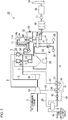
- FIG. 1 is the system diagram showing an enlarged view around the boiler of the coal-fired power plant 1 (hereinafter referred as "plant"), which is the first embodiment of a thermal power plant that is an aspect of the present invention.
- plant the coal-fired power plant 1
- FIG. 1 descriptions of the electrical system, various wires, or the like are omitted for clarity of the arrangement of constituents contributing the regenerative reheating cycle.
- the plant 1 is generally constructed from the boiler 2; the exhaust gas system 11; the steam system 3; the feed-water system 4; the high-pressure feed-water heater 10; the main economizer 36; the NOx removal equipment 14; and the sub economizer 40.
- the boiler 2 increases the temperature of feed-water by using heat obtained by combusting the fuel to generate steam.
- the exhaust gas system 11 circulates the combustion gas exhausted from the boiler 2 as the exhaust gas.
- the steam system 3 drives the high-pressure steam turbine 5H, the intermediate-pressure steam turbine 51, and the low-pressure steam turbine (omitted in the drawing) by using the steam generated by the boiler 2.
- the steam system 3 supplies the steam to the condenser (refer the reference symbol 6 in FIG. 3 ).
- the feed-water system 4 supplies condensate water obtained by the condenser to the boiler 2.
- the high-pressure feed-water heater 10 is provided to the feed-water system 4, and increases the temperature of feed-water by using the steam extracted from the steam turbines 5H, 51.
- the main economizer 36 is provided to the secondary side of the high-pressure feed-water heater 10 of the feed-water system 4 and in the boiler 2.
- the main economizer 36 increases the temperature of feed-water by using the combustion gas in the boiler 2.
- the NOx removal equipment 14 is provided to the secondary side of the exhaust gas from the main economizer 36 of the exhaust system 11.
- the exhaust gas at the required temperature or higher is supplied to the NOx removal equipment 14.
- the sub economizer 40 is provided between the high-pressure feed-water heater 10 of the feed-water system 4 and the main economizer 36, and increases the temperature of feed-water by using the exhaust gas on the secondary side of the NOx removal equipment 14.
- the exhaust gas system 11 has the flue 11A as shown in FIG. 1 .
- the exhaust gas system 11 has the catalytic NOx removal equipment 14 and the sub economizer 40 in the flue 11A, and has the regenerative air preheater 15 at the outlet of the flue 11A.
- the flue 11A has the gas duct 42, which is provided though the primary side (inlet side, upstream side) and the secondary side (outlet side, downstream side) of the exhaust gas from the sub economizer 40, and the gas amount control damper 43 provided to the gas duct 42.
- the gas duct 42 part of or all of the exhaust gas flowing in the flue 11A can be sent to the air preheater 15 free of passage through the sub economizer 40 (in other words, the sub economizer 40 can be bypassed).
- the gas amount control damper 43 the flow rate of the exhaust gas bypassing in the gas duct 42 can be controlled.
- the gas duct 42 and the gas amount control damper 42 constitute the exhaust gas temperature control device.
- the exhaust gas system 11 has: the dust collection device 16; the induced draft fan 17; the sulfur removal equipment 18; and the chimney 19 on the secondary side (subsequent stage) of the air preheater 15.
- the exhaust gas 11 is the flue channeling the combustion gas exhausted from the boiler 2 to the chimney 19 as the exhaust gas.
- the exhaust gas exhausted from the boiler 2 is sent to the sub economizer 40 after passage through the NOx removal equipment 14.
- the exhaust gas sent to the sub economizer 40 is sent to the regenerative air preheater 15 after heat exchanging with the feed-water on the secondary side of the high-pressure feed-water heater 10 of the feed-water system 4.
- the exhaust gas sent to the air preheater 15 passes through the dust collection device 16 and the sulfur removal equipment 18 after heat exchanging with the air for transporting pulverized coal in the primary air system 12 (hereinafter referred as "the primary air") and the air for combustion in the secondary air system 13 (hereinafter referred as "the secondary air"). Then, the exhaust gas is discharged into the atmosphere.
- the primary air system 12 has the primary air fan20; the steam air preheater 41; and the coal pulverizer 24. All of the primary air is sent to the air preheater 15. This primary air sent to the air preheater 15 is heated by heat exchanging with the exhaust gas from the boiler 2. Because of this, the primary air is introduced to the coal pulverizer 24 after being adjusted to the required temperature at the inlet of the coal pulverizer 24.
- the primary air introduced in the coal pulverizer 24 vaporizes the moisture in the pulverized coal by its potential heat, and transfers the dried pulverized coal to the pulverized coal burner provided to the boiler 2 to have the pulverized coal to be combusted.
- the fuel coal is supplied to the coal pulverizer 24 and pulverized to a predetermined grain size.
- the primary air is heated in advance by the steam air preheater 41 provided to the air duct between the primary air fan 20 and the air preheater 15.
- the secondary air system 13 has the forced draft fan 25. All of the secondary air is introduced in the air preheater 15. This secondary air sent to the air preheater 15 and heated by heat exchanging with the exhaust gas from the boiler 2. Then, the secondary air is introduced into the boiler 2 as the air for combustion by the pulverized coal burner and the air for the two staged combustion.
- the feed-water system 4 has: the deaerator 9; the boiler feed-water pump 45; the high-pressure feed-water heater 10; the sub economizer 40; and the main economizer 36.
- the steam extraction systems 29, 30, in which extraction steam from the intermediate-pressure steam turbine 51 flows are provided, respectively.
- the steam extraction system 31 is provided in which the extraction steam from the high-pressure steam turbine 5H flows.
- the drain pipes 33, 34 are piping in which drain from the high-pressure feed-water heater 10 flows.
- the high-pressure feed-water heater 10 is constituted from multiple heat exchangers. They are referred as the first high-pressure feed-water heater 26; and the second high-pressure feed-water heater 27 based on their locations from the deaerator 9 for the sake of simplicity. Feed-water heated by the high-pressure feed-water heater 10 is sent to the sub economizer 40 in the flue 11A.
- Each of heat exchangers of the high-pressure feed-water heater 10 heats feed-water by using the steam extracted from the intermediate-pressure steam turbine 51 and the high-pressure steam turbine 5H.
- the extraction system 30 sends the extraction steam to the first high-pressure feed-water heater 26; and the extraction system 31 sends the extraction steam to the second high-pressure feed-water heater 27.
- the extraction steam sent to the second high-pressure feed-water heater 2 becomes drain after heat exchanging with feed-water. This drain is sent to the first high-pressure feed-water heater 26 through the drain pipe 34.
- feed-water is heated by using the drain from the second high-pressure feed-water heater 27 and the extraction steam extracted from the extraction system 30. Then, the drain discharged from the first high-pressure feed-water heater 26 is sent to the deaerator 9 through the drain pipe 33.
- the steam system 3 has the evaporator 37; the superheater 38; the high-pressure steam turbine 5H; the reheater 39; and the intermediate-pressure steam turbine 51.
- Feed-water introduced from the feed-water system 4 to the main economizer 36 in the boiler 2 becomes superheated steam by passage through the evaporator 37 and the superheater 38. Then, the superheated feed-water is introduced into the high-pressure steam turbine 5H.
- the exhaust gas from the high-pressure steam turbine 5H is re-introduced into the boiler 2 and channeled to intermediate-pressure steam turbine 51 after re-heating by the reheater 39.
- the plant 1 of the present embodiment uses the selective catalytic reduction NOx removal equipment 14.
- the acidic ammonium sulfate is precipitated and the performance of the denitrification catalyst is reduced when the exhaust gas temperature at the inlet 14a of the NOx removal equipment 14 is low.
- the exhaust gas temperature at the inlet 114a of the NOx removal equipment 114 is a high temperature free of the acidic ammonium sulfate precipitation (generally, it is about 300°C or higher).
- the reduction of the performance of the denitrification catalyst due to precipitation of the acidic ammonium sulfate can be prevented in the present embodiment too by retaining the exhaust gas temperature (temperature of the exhaust gas on the primary side) at the inlet 14a of the NOx removal equipment 14 equivalent to that of the conventional coal-fired power plant 101.
- the exhaust gas is released into the atmosphere from the chimney in the state where the potential heat of the exhaust gas from the boiler is not sufficiently recovered in the actual situation. Furthermore, in the case where the heat recovery is attempted in the downstream of the air preheater 115, the heat-transfer area of the heat exchanger increases to cause a problem in which the device is oversized.
- the plant 1 of the present embodiment is configured to provide the sub economizer 40 to the flue 11A between the NOx removal equipment 14 and the air preheater 15 in addition to the main economizer 36 provided to the upstream (on the primary side) of the NOx removal equipment 14 as shown in FIG. 1 .
- the gas temperature on the outlet 15b side (on the secondary side) of the air preheater 15 can be reduced compared to the conventional coal-fired power plant 101 since the heat can be recovered to the boiler feed-water from the exhaust gas after passage through the NOx removal equipment 14. Therefore, by recovering the heat corresponding to the decrement of the gas temperatures on the outlet 15b side of the air preheater 15 to the boiler feed-water, the power generation efficiency of the plant 1 of the present embodiment is improved.
- the high-pressure feed-water heater 110 is consisted from three-staged heat exchanger in order to improve the turbine plant (water-steam) efficiency as shown in FIG. 4 .
- the feed-water is sent to the economizer 136 in the boiler 102 after the temperature of the feed-water is increased to about 280°C-290°C, for example, by the intermediate stage extraction steam of the high-pressure steam turbine 105H at the third high-pressure feed-water heater 128, which is the last stage of the high-pressure feed-water heater 110.
- the third high-pressure feed-water heater 128, which is the last heat exchanger in the conventional high-pressure feed-water heater 110, and the extraction steam system 132 are not provided; and the high-pressure feed-water heater 10 is constituted from the first and second high-pressure feed-water heaters 26, 27 in the plant 1 of the present embodiment as shown in FIG. 1 . Because of this, the feed-water, which is heated, for example to about 250°C, by using the extraction steam from the steam system 3 from the high-pressure steam turbine 5H to the reheater 39 in the second high-pressure feed-water heater 27, is sent to the sub economizer 40.
- the cold end temperature on the exhaust gas side can be reduced by setting a lower temperature of the feed-water temperature on the secondary side of the high-pressure feed-water heater 10 than the temperature on the secondary side of the last-stage of the high-pressure feed-water heater 110 of the conventional coal-fired power plant 101.
- the heat-transfer area of the sub economizer 40 can be reduced since a larger logarithmic mean temperature difference between the exhaust gas and the boiler feed-water can be obtained.
- the turbine plant efficiency is reduced with the reduction of the feed-water temperature on the outlet side (secondary side) of the second high-pressure feed-water heater 27, which is the last stage of the high-pressure feed-water heater 10.
- a suitable sub economizer 40 might not be practically unobtainable due to a concern on the device dimension, since the heat recovery efficiency from the exhaust gas in the sub economizer 40 is reduced and the needed heat-transfer area is increased.
- the turbine plant efficiency reduces 0.5-0.6% (relative value) in the case where the feed-water temperature is about 250°C compared to the case where the feed-water temperature on the outlet side (secondary side) of the final feed-water heater is 280-290°C.
- the heat-transfer area becomes equivalent of the heat-transfer area of the main economizer of the conventional coal-fired power plant 101 or less in the case where the feed-water temperature is about 250°C. Therefore, it is needed for the feed-water temperature to be determined in consideration with the balance, at which the heat recovery from the exhaust gas in the sub economizer 40 can be performed efficiently while the reduction of the turbine plant efficiency is suppressed at the minimum level.
- the plant 1 of the present embodiment has the air preheater 15 in the exhaust gas system 11 as shown in FIG. 1 .
- the exhaust gas temperature on the outlet 15b side of the air preheater 15 becomes low, low-temperature corrosion of the air preheater 15 due to sulfur content or the like in the exhaust gas components might be promoted. Therefore, it is preferable that the exhaust gas temperature on the outlet 15b side (secondary side) of the air preheater 15 is kept within the required temperature range. Promotion of the low-temperature corrosion on devices due to sulfur content or the like in the exhaust gas components can be prevented by keeping the exhaust gas on the outlet 15b side of the air preheater 15 within the predetermined temperature range.
- the temperature of the air preheater 15 at the cold end (secondary side of the exhaust gas) preventing the low-temperature corrosion is the lower limit.
- the air preheater 15 shown in FIG. 1 is a Ljungstrom type air preheater
- the plant 1 in order to prevent low-temperature corrosion on the cold end element, the plant 1 is controlled in such a way that the cold end average temperature becomes the recommended value shown in the technical literature (refer the drawing shown in page 167 in "Companion-Thermal and Nuclear Power Generation-Companion (7th Edition)" published from Thermal and Nuclear Power Engineering Society ) or higher.
- the meaning of the cold end average temperature is explained in the above-mentioned technical literature.
- the lower limit of the temperature on the secondary side of the exhaust gas of the air preheater is calculated from the recommended value of the cold end average temperature corresponding to the sulfur content in fuel using the drawing shown in the above-mentioned technical literature and the temperature on the primary side of the air of the air preheater.
- the recommended value of the cold end average temperature is 66°C or higher based on the drawing shown in the above-mentioned technical literature.
- the temperature on the primary side of the air of the air preheater is 40°C
- the lower limit of the temperature on the secondary side of the exhaust gas of the air preheater becomes 92°C as shown in the formula indicated below.
- Temperature on the secondary side of the exhaust gas 2 ⁇ Recommended value of the cold end average value ⁇
- the exhaust gas temperature on the outlet 15b side (secondary side) of the air preheater 15 becomes low due to the influence of a partial load operation; change of coal types; fluctuation in the atmospheric temperature; or the like, first, part or all of the exhaust gas bypasses the sub economizer 40 by introducing the exhaust gas into the gas duct 42 bypassing the sub economizer 40. Because of this, the amount of heat exchange in the sub economizer 40 can be reduced; and the exhaust gas temperature at the inlet 15a and the outlet 15b of the air preheater 15 can be increased.
- the primary air temperature after passage through the air preheater 15 is increased by heating the primary air on the primary side (inlet side) of the air preheater 15 by the steam air preheater 41 provided to the air duct between the primary air fan 20 and the air preheater 15.
- the plant 1 of the present embodiment by providing the sub economizer 40 to the flue 11A between the NOx removal equipment 14 and the air preheater 15, the high-temperature exhaust gas on the secondary side of the NOx removal equipment 14 can exchange heat efficiently with the boiler feed-water while the reduction of the denitrification catalyst performance is suppressed by keeping the exhaust gas temperature on the inlet 14a side of the NOx removal equipment 14 to the temperature free of the acidic ammonium sulfate precipitation.
- the plant 1 of the present embodiment is free of the third high-pressure feed-water heater 128 (the high-pressure feed-water heater 110), which heats feed-water to about 285°C by using the extraction steam of the intermediate stage of the high-pressure steam turbine 105H in the conventional coal-fired power plant 101. Because of this, the cold end temperature on the exhaust gas side can be reduced since the feed-water temperature on the secondary side of the second high-pressure feed-water heater 27, which is the last stage, of the high-pressure feed-water heater 10 can be lowered to about 250°C. At the same time, a larger logarithmic mean temperature difference between the exhaust gas and the boiler feed-water can be obtained. Therefore, the heat-transfer area of the sub economizer 40 can be reduced to the level equivalent to the main economizer 36.
- the exhaust heat of the exhaust gas from the boiler can be recovered to the main feed-water system by proving the sub economizer 40.
- higher power generation efficiency can be obtained compared to the conventional coal-fired power plant 101.
- the plant 1 of the present embodiment is free of the third high-pressure feed-water heater 128 (the high-pressure feed-water heater 110), which heats feed-water to about 285°C by using the extraction steam of the intermediate stage of the high-pressure steam turbine 105H in the conventional coal-fired power plant 101. Because of this, the main steam flow rate corresponding to the amount of the extraction steam in the intermediate stage at the high-pressure steam turbine 5H can be reduced. Thus, the facility of: the main water pipe; the main economizer; the evaporator; the superheater; the main steam pipe; and the high-pressure steam turbine, can be down-sized. Therefore, the construction cost can be reduced. In addition, the construction for the unnecessary extraction steam system 132 and the third high-pressure feed-water heater 128 can be saved.
- all of the primary air can be forced to pass the air preheater 15 since the plant 1 has the temperature increasing device that increases the temperature of the primary air (steam air preheater 41).
- steam air preheater 41 the temperature increasing device that increases the temperature of the primary air
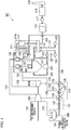
- the present embodiment has different configurations to the plant 1 and the method of operating the plant 1 of the first embodiment. Therefore, the thermal power plant and the method of operating the thermal power plant of the present embodiment are explained by using FIG. 2 .
- the same reference symbols as the first embodiment are used for the identical constituents to the first embodiment, and detail explanations for them are omitted.
- the coal-fired power plant 51 of the present embodiment has the configuration in which the feed-water pipe 52; and the feed-water amount control valve 53, both of which corresponds to the exhaust gas temperature control device, replace the gas duct 42; and the gas amount control damper 43 (refer FIG. 1 ), both of which constitute the exhaust gas temperature control device in the plant 1 of the first embodiment as shown in FIG. 2 .
- the feed-water system 4 has: the feed-water pipe 52 provided from the primary side (inlet side, upstream side) to the secondary side (outlet side, downstream side) of the sub economizer 40; and the feed-water amount control valve 53 provided to the feed-water pipe 52, as shown in FIG. 2 .
- the feed-water pipe 52 part or all of feed-water flowing in the feed-water system 4 can be sent to the main economizer 36 free of passage through the sub economizer 40 (in other words, the feed-water bypasses the sub economizer 40).
- the feed-water amount control valve 53 the flow rate of feed-water bypassing in the feed-water pipe 52 can be controlled.
- the exhaust gas temperature control device is constituted from the feed-water pipe 52 and the feed-water amount control valve 53.
- first, part or all of the exhaust gas bypasses the sub economizer 40 by introducing feed-water into the feed-water pipe 52 bypassing the sub economizer 40 by using the feed-water amount control valve 53.
- the amount of heat exchange in the sub economizer 40 can be reduced; and the exhaust gas temperature at the inlet 15a and the outlet 15b of the air preheater 15 can be increased.
- the heat exchangers of the high-pressure feed-water heater 10 is configured to be two-staged in the plant 1 of the embodiment as shown in FIG. 1 , it is not limited to this configuration as long as the feed-water temperature on the secondary side of the last heat exchanger is configured to be the required temperature in the high-pressure feed-water heater 10.
- the configuration related to the number of the stages of the low-pressure feed-water heater 8 can be appropriately selected as shown FIG. 3 .
- Temperatures indicted in the descriptions of the above-described embodiments are only for an example purpose and the present invention is not limited by the descriptions. Appropriately selected temperatures can be set when the configuration of the plant and the situation the in which plant is operated are changed.
- the main steam flow rate supplied to the high-pressure steam turbine 105H was about 1,560 t/h during a rated power operation.
- the amount of extraction steam from the extraction steam system 132, which was provided to the intermediate stage of the high-pressure steam turbine 105H, to the third high-pressure feed-water heater 128 was about 110 t/h.
- the feed water temperature on the outlet side (secondary side) of the third high-pressure feed-water heater 128 of the feed-water system 104 was about 285°C by the above-described extraction steam.
- the feed-water heated by the third high-pressure feed-water heater 128 was supplied to the economizer 136.
- the exhaust gas temperature on the secondary side (outlet side) of the NOx removal equipment 114 of the exhaust gas system 111 was about 360°C.
- the exhaust gas temperature on the secondary side (outlet side) of the air preheater 115 of the exhaust gas system 111 was about 140°C.
- the power needed for the induced draft fan 117 of the exhaust gas system 111 was about 7,200kW.
- Example of an aspect of the present invention The coal-fired power plant 1 was free of the third high-pressure feed-water heater 128 and the extraction steam system 132 of the conventional coal-fired power plant 101; and had the sub economizer 40 which was not present in the configuration of the conventional coal-fired power plant 101.
- the main steam flow rate supplied to the high-pressure steam turbine 5H was about 1,450 t/h during a rated power operation. This was because of reduction of the steam flow of about 110 t/h, which corresponded to the amount of extraction steam to the high-pressure feed-water heater 128 from the extraction steam system 132 provided to the intermediate stage of the high-pressure steam turbine 105H in the conventional coal-fired power plant 101.
- the feed-water temperature on the outlet side (secondary side) of the second high-pressure feed-water heater 27, which was the last stage of the high-pressure feed-water heater 10 of the feed-water system 3, was about 250°C, meaning that the temperature was reduced about 35°C compared to the above-described Comparative Example 1.
- the feed-water heated by the second high-pressure feed-water heater 27 was supplied to the sub economizer 40.
- the exhaust gas temperature on the primary side (inlet 14a side) of the NOx removal equipment 14 of the exhaust gas system 11 was about 360°C as in the above-described Comparative Example 1.
- the exhaust gas temperature on the secondary side (outlet side) of the air preheater 15 of the exhaust gas system 11 was about 110°C, meaning that the temperature was reduced about 30°C compared to the above-described Comparative Example 1.
- the power needed for the induced draft fan 17 of the exhaust gas system 11 was about 6,700 kW, meaning that the power needed was reduced about 500 kW compared to the above-described Comparative Example 1. This is because of reduction of volume due to lowered temperature of the exhaust gas flowing in the exhaust gas system 11.
- the gross thermal efficiency was calculated by the formula, (Boiler efficiency ⁇ Turbine plant efficiency ⁇ (100 - Plant loss))/10000. Accordingly, it was confirmed that the gross thermal efficiency was improved about 0.4% from 43.0% (Comparative Example 1) to 43.4% (Example 1 of the present invention) as a whole.
- the volume of the exhaust gas reduces by decreasing the temperature of the exhaust gas on the secondary side (outlet side) of the air preheater 15 to 110°C. Accordingly, it was confirmed that the auxiliary power ratio was improved about 0.1% from 5.5% (Comparative Example 1) to 5.4%
- the net thermal efficiency was calculated from the formula, (Gross thermal efficiency ⁇ (100 - Auxiliary power ratio))/100.
- the cost reduction effect during plant construction can be obtained from the coal-fired power plant of Example 1 of the present invention.
- the required main steam flow can be reduced from 1560 t/h (Comparative Example 1) to 1450 t/h (Example 1 of the present invention) during a rated power operation.
- extraction steam from the high-pressure steam turbine 105H to the third high-pressure feed-water heater 128 was performed at 110 t/h, in the coal-fired power plant 101 of Comparative Example 1.
- the steam flow corresponding to the extraction steam can be reduced in Example 1 of the present invention.
- the sub economizer 40 is added in the coal-fired power plant 1 of Example 1.
- the additional cost for providing the sub economizer 40 is limited since the heat transferring part of the sub economizer 40 is not exposed to the high temperature. Therefore, according to the present invention, the usage amount of the material part that is particularly expensive can be reduced, and the cost for plant construction can be reduced.
- the volume of the exhaust gas is reduced compared to the above-described Comparative Example 1 because of lowering the exhaust gas temperature on the secondary side (outlet side) of the air preheater 15 of the exhaust gas system 11 to about 110°C. Because of this, the power needed for the induced draft fan 17 can be reduced; and the devices provided to the exhaust system 11 can be down-sized. Therefore, the plant construction cost can be reduced.
- the volume of the exhaust gas is reduced compared to the above-described Comparative Example 1 because of lowering the exhaust gas temperature on the secondary side (outlet side) of the air preheater 15 of the exhaust gas system 11 to about 110°C. Because of this, the power needed for the induced draft fan 17 can be reduced; and the devices provided to the exhaust system 11 can be down-sized. Therefore, the plant construction cost can be reduced.
Landscapes
- Engineering & Computer Science (AREA)
- Mechanical Engineering (AREA)
- General Engineering & Computer Science (AREA)
- Chemical & Material Sciences (AREA)
- Combustion & Propulsion (AREA)
- Physics & Mathematics (AREA)
- Thermal Sciences (AREA)
- Air Supply (AREA)
- Control Of Turbines (AREA)
- Engine Equipment That Uses Special Cycles (AREA)
- Chimneys And Flues (AREA)
Claims (9)
- Wärmekraftwerk, umfassend:einen Kessel (2), der konfiguriert ist, um Dampf durch Erhöhen einer Temperatur von Speisewasser unter Verwendung von Hitze, erhalten durch das Verbrennen eines Brennstoffs, zu erzeugen,ein Dampfsystem (3), aufweisend eine Hochdruck-Dampfturbine, einen Wiedererhitzer und eine Zwischendruck-Dampfturbine;ein Abgassystem (11), das konfiguriert ist, um ein Verbrennungsgas zirkulieren zu lassen, das vom Kessel (2) nach dem Verbrennen des Brennstoffs als Abgas abgelassen wird;ein Speisewassersystem (4), das konfiguriert ist, dem Kessel (2) Wasser zuzuführen;und ein Speisewassererhitzer (10), der dem Speisewassersystem (4) bereitgestellt und konfiguriert ist, um die Temperatur des Speisewassers unter Verwendung von Extraktionsdampf zu erhöhen;einen Hauptvorwärmer (36), der einer sekundären Seite des Speisewassers vom Speisewassererhitzer (10) des Speisewassersystems (4) bereitgestellt und konfiguriert ist, um die Temperatur des Speisewassers unter Verwendung von Resthitze des Verbrennungsgases zu erhöhen; undeine katalytische NOx-Entfernungsausrüstung (14), die einer sekundären Seite des Abgases vom Hauptvorwärmer (36) des Abgassystems (11) bereitgestellt ist, und das Abgas bei 300 ºC oder höher konfiguriert ist, um zugeführt zu werden, wobeiein Untervorwärmer (40), der konfiguriert ist, um die Temperatur des Speisewassers unter Verwendung des Abgases auf einer sekundären Seite der NOx-Entfernungsausrüstung (14) zu erhöhen, zwischen dem Speisewassererhitzer (10) und dem Hauptvorwärmer (36) des Speisewassersystems (4) bereitgestellt ist,das Speisewasser, eingeführt vom Speisewassersystem (4) in den Kessel (2), zu Heißdampf wird,der Heißdampf in die Hochdruck-Dampfturbine eingeführt und erneut in den Kessel (2) eingeführt wird, nachdem er in die Hochdruck-Dampfturbine eingeführt wurde,Dampf, der von der Hochdruck-Dampfturbine abgelassen und erneut in den Kessel (2) eingeführt wird, in die Zwischendruck-Dampfturbine eingeführt wird, nachdem er im Wiedererhitzer wiedererhitzt wurde,der Speisewassererhitzer (10) einen ersten Speisewassererhitzer (26) und einen zweiten Speisewassererrhitzer (27) umfasst, in einer Reihenfolge von einer vorgelagerten Seite des Speisewassers,ein erstes Extraktionssystem (30), in dem extrahierter Dampf von der Zwischendruck-Dampfturbine fließt, zwischen der Zwischendruck-Dampfturbine und dem ersten Speisewassererhitzer (26) bereitgestellt ist, undein zweites Extraktionssystem (31), in dem extrahierter Dampf von der Hochdruck-Dampfturbine zum Wiedererhitzer fließt, zwischen der Hochdruck-Dampfturbine und dem zweiten Speisewassererhitzer (27) bereitgestellt ist,dadurch gekennzeichnet, dassder Untervorwärmer (40) eine Abgastemperatur-Steuervorrichtung umfasst, die konfiguriert ist, um eine Temperatur des Abgases auf einer sekundären Seite des Untervorwärmers (40) zu steuern, unddie Abgastemperatur-Steuervorrichtung Folgendes umfasst: ein Gasrohr (42), das von einer primären Seite zu einer sekundären Seite des Abgases vom Untervorwärmer (40) des Abgassystems (11) bereitgestellt ist, und einen Gasmengen-Steuerdämpfer, der dem Gasrohr (42) bereitgestellt ist.
- Wärmekraftwerk nach Anspruch 1, wobei die Abgastemperatur-Steuervorrichtung Folgendes umfasst: eine Speisewasserpumpe, die von einer primären Seite zu einer sekundären Seite des Speisewassers vom Untervorwärmer (40) des Speisewassersystems (4) bereitgestellt ist, und ein Speisewassermengen-Steuerventil, das dem Speisewasserrohr bereitgestellt ist.
- Wärmekraftwerk nach Anspruch 1 oder 2, weiter umfassend
ein Luftsystem, das konfiguriert ist, um dem Kessel (2) Luft zuzuführen, und
einen Luftvorherhitzer (15), der einer sekundären Seite des Abgases vom Untervorwärmer (40) des Abgassystems (11) bereitgestellt und konfiguriert ist, um eine Temperatur von Luft des Luftsystems unter Verwendung des Abgases auf der sekundären Seite des Untervorwärmers (40) zu erhöhen, wobei
eine Temperatur des Abgases auf der sekundären Seite des Luftvorerhitzers (15) gleich wie oder höher als eine Temperatur ist, erhalten durch die Formel 2 x (empfohlener Wert des durchschnittlichen Werts des kalten Endes) - (Temperatur auf der primären Seite der Luft des Luftvorerhitzers). - Wärmekraftwerk nach Anspruch 3, wobei
das Luftssystem Folgendes umfasst: ein primäres Luftsystem; und ein sekundäres Luftsystem, und
eine Temperaturerhöhungsvorrichtung, die konfiguriert ist, um die Temperatur von Luft auf einer primären Seite des Luftvorerhitzers (15) zu erhöhen, der dem primären Luftsystem bereitgestellt ist. - Wärmekraftwerk nach Anspruch 4, wobei die Temperaturerhöhungsvorrichtung ein Dampfluftvorerhitzer (41) ist, der konfiguriert ist, um die Luft unter Verwendung von Dampf zu erhitzen.
- Wärmekraftwerk nach Anspruch 4 oder 5, wobei eine Kohlenmühle (24) dem primären Luftsystem auf der sekundären Seite des Luftvorerhitzers (15) bereitgestellt ist.
- Verfahren zum Betreiben eines Wärmekraftwerks, umfassend:ein Abgassystem (11), das konfiguriert ist, um ein Verbrennungsgas das von einem Kessel (2) abgelassen wird, als ein Abgas zirkulieren zu lassen;ein Speisewassersystem (4), das konfiguriert ist, um dem Kessel (2) Wasser zuzuführen;einen Speisewassererhitzer (10), der dem Speisewassersystem (4) bereitgestellt und konfiguriert ist, um die Temperatur des Speisewassers unter Verwendung von Extraktionsdampf zu erhöhen; undein Luftsystem, das konfiguriert ist, um dem Kessel Luft (2) zuzuführeneinen Hauptvorwärmer (36), der einer sekundären Seite des Speisewassers vom Speisewassererhitzer (10) des Speisewassersystems (4) bereitgestellt und konfiguriert ist, um die Temperatur des Speisewassers unter Verwendung von Resthitze des Verbrennungsgases zu erhöhen;eine katalytische NOx-Entfernungsausrüstung (14), die einer sekundären Seite des Abgases vom Hauptvorwärmer (36) des Abgassystems (11) bereitgestellt ist, und das Abgas bei 300 ºC oder höher konfiguriert ist, um zugeführt zu werden;einen Hauptvorwärmer (40), der zwischen dem Speisewassererhitzer (10) und dem Hauptvorwärmer (36) des Speisewassersystems (4) bereitgestellt ist, um die Temperatur des Speisewassers unter Verwendung des Abgases auf einer sekundären Seite der NOx-Entfernungsausrüstung (14) zu erhöhen,ein Dampfsystem (3) aufweisend eine Hochdruck-Dampfturbine, einen Wiedererhitzer und eine Zwischendruck-Dampfturbine; undeinen Luftvorherhitzer (15), der einer sekundären Seite des Abgases vom Untervorwärmer (40) bereitgestellt und konfiguriert ist, um eine Temperatur von Luft des Luftsystems unter Verwendung des Abgases auf der sekundären Seite des Untervorwärmers (40) zu erhöhen,wobei das Verfahren den Schritt des Steuerns einer Temperatur des Abgases auf einer sekundären Seite des Luftvorerhitzers (15) des Abgassystems (11) derart umfasst, dass die Temperatur gleich wie oder höher als eine Temperatur ist, erhalten durch eine Formel 2x (empfohlener Wert des durchschnittlichen Werts des kalten Endes) - (Temperatur auf der primären Seite der Luft des Vorerhitzers), wobeidas Speisewasser, eingeführt vom Speisewassersystem (4) in den Kessel (2) zu Heißdampf wird,der Heißdampf in die Hochdruck-Dampfturbine eingeführt und erneut in den Kessel (2) eingeführt wird, nachdem er in die Hochdruck-Dampfturbine eingeführt wurde,Dampf, der von der Hochdruck-Dampfturbine abgelassen und erneut in den Kessel (2) eingeführt wird, in die Zwischendruck-Dampfturbine eingeführt wird, nachdem er im Wiedererhitzer wiedererhitzt wurde,der Speisewassererhitzer (10) einen ersten Speisewassererhitzer (26) und einen zweiten Speisewassererhitzer (27) in einer Reihenfolge von einer vorgelagerten Seite des Speisewassers umfasst,ein erstes Extraktionssystem (30), in dem extrahierter Dampf von der Zwischendruck-Dampfturbine fließt, zwischen der Zwischendruck-Dampfturbine und dem ersten Speisewassererhitzer (26) bereitgesetellt ist, undein zweites Extraktionssystem (31), in dem extrahierter Dampf von der Hochdruck-Dampfturbine in den Wiedererhitzer fließt, zwischen der Hochdruck-Dampfturbine und dem zweiten Speisewassererhitzer (27) bereitgestellt ist,der Untervorwärmer (40) eine Abgastemperatur-Steuervorrichtung umfasst, die konfiguriert ist, um eine Temperatur des Abgases auf einer sekundären Seite des Untervorwärmers (40) zu steuern, unddie Abgastemperatur-Steuervorrichtung Folgendes umfasst: ein Gasrohr (42), das von einer primären Seite zu einer sekundären Seite des Abgases vom Untervorwärmer (40) des Abgassystems (11) bereitgestellt ist; und ein Gasmengen-Steuerdämpfer, der auf dem Gasrohr (42) bereitgestellt ist.
- Verfahren zum Betrieb eines Wärmekraftwerks nach Anspruch 7, wobei ein Teil oder die Gesamtheit des Abgases im Abgassystem (11) an den Luftvorerhitzer (15) ohne den Durchgang durch den Untervorwärmer (40) geschickt wird.
- Verfahren zum Betrieb eines Wärmekraftwerks nach Anspruch 7, wobei ein Teil oder die Gesamtheit des Speisewassererhitzers im Speisewassersystems (4) an den Hauptvorwärmer (36) ohne den Durchgang durch den Untervorwärmer (40) geschickt wird.
Applications Claiming Priority (2)
| Application Number | Priority Date | Filing Date | Title |
|---|---|---|---|
| JP2013109118A JP5624646B1 (ja) | 2013-05-23 | 2013-05-23 | 火力発電プラント及び火力発電プラントの運転方法。 |
| PCT/JP2014/059524 WO2014188790A1 (ja) | 2013-05-23 | 2014-03-31 | 火力発電プラント及び火力発電プラントの運転方法 |
Publications (3)
| Publication Number | Publication Date |
|---|---|
| EP3001104A1 EP3001104A1 (de) | 2016-03-30 |
| EP3001104A4 EP3001104A4 (de) | 2017-03-08 |
| EP3001104B1 true EP3001104B1 (de) | 2018-07-04 |
Family
ID=51933356
Family Applications (1)
| Application Number | Title | Priority Date | Filing Date |
|---|---|---|---|
| EP14801816.1A Active EP3001104B1 (de) | 2013-05-23 | 2014-03-31 | Kraftwerk mit fossilem brennstoff und betriebsverfahren für ein kraftwerk mit fossilem brennstoff |
Country Status (6)
| Country | Link |
|---|---|
| US (1) | US9927117B2 (de) |
| EP (1) | EP3001104B1 (de) |
| JP (1) | JP5624646B1 (de) |
| KR (1) | KR101610613B1 (de) |
| CN (2) | CN109780566A (de) |
| WO (1) | WO2014188790A1 (de) |
Families Citing this family (10)
| Publication number | Priority date | Publication date | Assignee | Title |
|---|---|---|---|---|
| JP6737611B2 (ja) * | 2016-03-25 | 2020-08-12 | 三菱日立パワーシステムズ株式会社 | 火力発電システム及び火力発電システムの制御方法 |
| KR101816212B1 (ko) * | 2016-09-12 | 2018-01-08 | 두산중공업 주식회사 | 연소물의 특성 요소의 영향도 분석 장치 |
| JP6224858B1 (ja) * | 2017-03-17 | 2017-11-01 | 三菱日立パワーシステムズ株式会社 | 発電プラント及びその運転方法 |
| CN107238071A (zh) * | 2017-07-20 | 2017-10-10 | 合肥裕朗机电科技有限公司 | 一种电站锅炉蒸发循环装置 |
| AU2017425082B2 (en) * | 2017-07-27 | 2021-06-03 | Sumitomo SHI FW Energia Oy | A fluidized bed boiler plant and a method of preheating combustion gas in a fluidized bed boiler plant |
| CN108643980B (zh) * | 2018-04-17 | 2022-09-13 | 章礼道 | 超高压缸和高中压缸均带有附加回热级的二次再热机组 |
| KR102590497B1 (ko) * | 2021-10-18 | 2023-10-17 | 한국전력공사 | 석탄 화력 발전소용 버너 및 이를 포함한 석탄 화력 발전소 재활용 발전 시스템 |
| CN114076303A (zh) * | 2021-10-20 | 2022-02-22 | 华电电力科学研究院有限公司 | 利用工业供热外供蒸汽凝结水余热加热主机凝结水的系统及方法 |
| BE1030715B1 (nl) * | 2022-07-13 | 2024-02-12 | Keppel Seghers Belgium Nv | Werkwijze voor het opwekken van stoom in combinatie met een energieopwekkingsproces alsook installatie hiervoor |
| CN115507417A (zh) * | 2022-09-30 | 2022-12-23 | 西安热工研究院有限公司 | 一种燃煤发电机组节能及供热协同改造系统及运行方法 |
Family Cites Families (32)
| Publication number | Priority date | Publication date | Assignee | Title |
|---|---|---|---|---|
| US3485048A (en) * | 1968-06-28 | 1969-12-23 | Emmanuel Stephen Miliaras | Increased vapor generator output feature |
| US3818872A (en) * | 1973-06-29 | 1974-06-25 | Combustion Eng | Economizer bypass for increased furnace wall protection |
| CA1092910A (en) * | 1976-07-27 | 1981-01-06 | Ko'hei Hamabe | Boiler apparatus containing denitrator |
| JPS5315639A (en) * | 1976-07-27 | 1978-02-13 | Hitachi Zosen Corp | Boiler has denitration device built-in |
| US4442795A (en) * | 1982-04-26 | 1984-04-17 | Electrodyne Research Corporation | Recirculating fluidized bed combustion system for a steam generator |
| JP2923172B2 (ja) * | 1993-06-22 | 1999-07-26 | 三菱重工業株式会社 | 節炭器装置 |
| US5423272A (en) * | 1994-04-11 | 1995-06-13 | Combustion Engineering, Inc. | Method for optimizing the operating efficiency of a fossil fuel-fired power generation system |
| US5554350A (en) * | 1994-12-15 | 1996-09-10 | Combustion Engineering, Inc. | Air pollution control and heat recovery system and process for coal fired power plant |
| JPH0926105A (ja) * | 1995-07-12 | 1997-01-28 | Mitsubishi Heavy Ind Ltd | ボイラ |
| JP3095745B1 (ja) | 1999-09-09 | 2000-10-10 | 三菱重工業株式会社 | 超高温発電システム |
| DE10001997A1 (de) * | 2000-01-19 | 2001-07-26 | Alstom Power Schweiz Ag Baden | Verbund-Kraftwerk sowie Verfahren zum Betrieb eines solchen Verbund-Kraftwerkes |
| JP3716188B2 (ja) * | 2001-04-10 | 2005-11-16 | 三菱重工業株式会社 | ガスタービンコンバインドプラント |
| ES2433687T3 (es) * | 2001-05-29 | 2013-12-12 | Andritz Oy | Método y disposición para producir energía eléctrica en una fábrica de pasta papelera |
| JP2002206702A (ja) * | 2001-11-15 | 2002-07-26 | Hitachi Ltd | コンバインドサイクルプラントの給水系装置および排熱回収ボイラ |
| US7599750B2 (en) * | 2005-12-21 | 2009-10-06 | Pegasus Technologies, Inc. | Model based sequential optimization of a single or multiple power generating units |
| EP2103339B8 (de) * | 2006-12-27 | 2021-01-20 | Mitsubishi Power, Ltd. | Abgasbehandlungsverfahren und vorrichtung |
| CN101140062B (zh) * | 2007-10-19 | 2011-05-18 | 冼泰来 | 多功能真空循环水仓 |
| CN101260815B (zh) * | 2008-04-24 | 2010-06-02 | 华北电力大学 | 抛物面槽式太阳能集热器辅助燃煤锅炉的混合热发电系统 |
| CN101261002B (zh) * | 2008-04-30 | 2011-02-09 | 华北电力大学 | 超或超超临界燃煤发电热力系统的改进方法 |
| JP5302597B2 (ja) * | 2008-08-21 | 2013-10-02 | 株式会社タクマ | 排ガス処理装置及び排ガス処理方法 |
| US20110094228A1 (en) | 2009-10-22 | 2011-04-28 | Foster Wheeler Energy Corporation | Method of Increasing the Performance of a Carbonaceous Fuel Combusting Boiler System |
| CN201715492U (zh) * | 2010-05-28 | 2011-01-19 | 济南市琦泉热电有限责任公司 | 一种用不同压力等级蒸汽的机组回热系统 |
| JP2011247553A (ja) * | 2010-05-31 | 2011-12-08 | Hitachi Ltd | 酸素燃焼ボイラ |
| US9459005B2 (en) * | 2010-09-01 | 2016-10-04 | The Babcock & Wilcox Company | Steam cycle efficiency improvement with pre-economizer |
| CN102031999A (zh) * | 2010-11-23 | 2011-04-27 | 江苏丰泰冷却塔有限公司 | 具有高效循环系统的火力发电机组 |
| CN102175021B (zh) * | 2011-01-27 | 2013-04-03 | 章礼道 | 能全面回收工质和热量的无泵直流炉启动系统 |
| US20120222591A1 (en) * | 2011-03-04 | 2012-09-06 | Foster Wheeler North America Corp. | Method of and Apparatus for Selective Catalytic NOx Reduction in a Power Boiler |
| KR20130028537A (ko) | 2011-09-09 | 2013-03-19 | 한국전력공사 | 발전 시스템 |
| CN102537933B (zh) * | 2011-12-30 | 2014-11-05 | 冯伟忠 | 一种用于汽轮发电机组的可调式给水回热系统 |
| CN202709159U (zh) * | 2012-07-05 | 2013-01-30 | 东方电气集团东方锅炉股份有限公司 | 一种可满足scr脱硝装置全负荷运行低排烟温度的锅炉 |
| CN102937297B (zh) | 2012-11-20 | 2015-04-08 | 上海锅炉厂有限公司 | 适用于在脱硝设备所有负荷下投运的锅炉省煤器 |
| CN102937295B (zh) | 2012-11-20 | 2015-02-18 | 上海锅炉厂有限公司 | 一种适用脱硝设备负全程负荷投运的锅炉省煤器布置方式 |
-
2013
- 2013-05-23 JP JP2013109118A patent/JP5624646B1/ja active Active
-
2014
- 2014-03-31 WO PCT/JP2014/059524 patent/WO2014188790A1/ja not_active Ceased
- 2014-03-31 EP EP14801816.1A patent/EP3001104B1/de active Active
- 2014-03-31 CN CN201910106732.1A patent/CN109780566A/zh active Pending
- 2014-03-31 KR KR1020157034091A patent/KR101610613B1/ko active Active
- 2014-03-31 US US14/892,190 patent/US9927117B2/en active Active
- 2014-03-31 CN CN201480029065.7A patent/CN105247286A/zh active Pending
Non-Patent Citations (1)
| Title |
|---|
| None * |
Also Published As
| Publication number | Publication date |
|---|---|
| JP2014228218A (ja) | 2014-12-08 |
| JP5624646B1 (ja) | 2014-11-12 |
| EP3001104A4 (de) | 2017-03-08 |
| WO2014188790A1 (ja) | 2014-11-27 |
| KR20150144808A (ko) | 2015-12-28 |
| CN109780566A (zh) | 2019-05-21 |
| KR101610613B1 (ko) | 2016-04-08 |
| US9927117B2 (en) | 2018-03-27 |
| EP3001104A1 (de) | 2016-03-30 |
| US20160091197A1 (en) | 2016-03-31 |
| CN105247286A (zh) | 2016-01-13 |
Similar Documents
| Publication | Publication Date | Title |
|---|---|---|
| EP3001104B1 (de) | Kraftwerk mit fossilem brennstoff und betriebsverfahren für ein kraftwerk mit fossilem brennstoff | |
| CN1074084C (zh) | 燃气蒸汽联合发电厂 | |
| US8186142B2 (en) | Systems and method for controlling stack temperature | |
| EP3438535B1 (de) | Verfahren und vorrichtung zur wärmegewinnung aus grundasche | |
| RU2688078C2 (ru) | Работающая на угле электростанция с оксисжиганием с интеграцией тепла | |
| CN101713334A (zh) | 通过使用调峰循环废热回收的联合循环动力增强进行峰值负载管理 | |
| US10288279B2 (en) | Flue gas heat recovery integration | |
| KR20190052118A (ko) | 열교환 시스템, 가스 터빈의 냉각 시스템 및 냉각 방법 및 가스 터빈 시스템 | |
| EP2513477B1 (de) | Sonnenenergieanlage mit integrierter gasturbine | |
| JPH05209502A (ja) | 管巣燃焼型コンバスタ−を備えたガスタ−ビン装置 | |
| JPH1113488A (ja) | 蒸気冷却型ガスタービンを用いた排気再燃コンバインドプラント | |
| JPH09209715A (ja) | 排気再燃型コンバインドプラントの低温腐食防止装置 | |
| CN205424888U (zh) | 加热锅炉一、二次风的二次再热汽轮机回热能量利用系统 | |
| CN206281365U (zh) | 一种高温废气余热利用系统 | |
| JP2766687B2 (ja) | 複合発電プラント | |
| JP2018119772A (ja) | 排熱利用発電システム、制御装置、制御方法及び排熱利用発電システムの製造方法 | |
| CN120008060B (zh) | 一种电站锅炉烟气余热深度回热系统的构建方法及系统 | |
| JPS5820914A (ja) | 高炉ガス焚き発電プラント | |
| Tawney et al. | Economic and performance evaluation of combined cycle repowering options | |
| JP2000130107A (ja) | ガスタービン併設式複合サイクル発電設備 | |
| JP2000220412A (ja) | 汽力発電設備のリパワリングシステム | |
| Serbetci | Optimization concerns for combined cycle power plants: II—optimum fuel gas heating | |
| JP2024166830A (ja) | ボイラシステムおよびボイラシステムの運転方法 | |
| Chen et al. | A Novel Combustion Air Preheating System in a Large-Scale Coal-Fired Power Unit | |
| JP2023123154A (ja) | ボイラシステム用の配管ユニット、ボイラシステムの改造方法、及びボイラシステム |
Legal Events
| Date | Code | Title | Description |
|---|---|---|---|
| PUAI | Public reference made under article 153(3) epc to a published international application that has entered the european phase |
Free format text: ORIGINAL CODE: 0009012 |
|
| 17P | Request for examination filed |
Effective date: 20151202 |
|
| AK | Designated contracting states |
Kind code of ref document: A1 Designated state(s): AL AT BE BG CH CY CZ DE DK EE ES FI FR GB GR HR HU IE IS IT LI LT LU LV MC MK MT NL NO PL PT RO RS SE SI SK SM TR |
|
| AX | Request for extension of the european patent |
Extension state: BA ME |
|
| DAX | Request for extension of the european patent (deleted) | ||
| A4 | Supplementary search report drawn up and despatched |
Effective date: 20170203 |
|
| RIC1 | Information provided on ipc code assigned before grant |
Ipc: F22D 1/02 20060101ALI20170130BHEP Ipc: F23J 15/00 20060101AFI20170130BHEP Ipc: F22D 1/40 20060101ALI20170130BHEP Ipc: F23L 15/00 20060101ALI20170130BHEP Ipc: F01K 7/22 20060101ALI20170130BHEP Ipc: F01K 7/40 20060101ALI20170130BHEP Ipc: F22D 1/34 20060101ALI20170130BHEP |
|
| GRAP | Despatch of communication of intention to grant a patent |
Free format text: ORIGINAL CODE: EPIDOSNIGR1 |
|
| STAA | Information on the status of an ep patent application or granted ep patent |
Free format text: STATUS: GRANT OF PATENT IS INTENDED |
|
| INTG | Intention to grant announced |
Effective date: 20180216 |
|
| GRAS | Grant fee paid |
Free format text: ORIGINAL CODE: EPIDOSNIGR3 |
|
| GRAA | (expected) grant |
Free format text: ORIGINAL CODE: 0009210 |
|
| STAA | Information on the status of an ep patent application or granted ep patent |
Free format text: STATUS: THE PATENT HAS BEEN GRANTED |
|
| AK | Designated contracting states |
Kind code of ref document: B1 Designated state(s): AL AT BE BG CH CY CZ DE DK EE ES FI FR GB GR HR HU IE IS IT LI LT LU LV MC MK MT NL NO PL PT RO RS SE SI SK SM TR |
|
| REG | Reference to a national code |
Ref country code: GB Ref legal event code: FG4D |
|
| REG | Reference to a national code |
Ref country code: CH Ref legal event code: EP |
|
| REG | Reference to a national code |
Ref country code: AT Ref legal event code: REF Ref document number: 1014924 Country of ref document: AT Kind code of ref document: T Effective date: 20180715 |
|
| REG | Reference to a national code |
Ref country code: IE Ref legal event code: FG4D |
|
| REG | Reference to a national code |
Ref country code: DE Ref legal event code: R096 Ref document number: 602014027984 Country of ref document: DE |
|
| REG | Reference to a national code |
Ref country code: NL Ref legal event code: MP Effective date: 20180704 |
|
| REG | Reference to a national code |
Ref country code: LT Ref legal event code: MG4D |
|
| REG | Reference to a national code |
Ref country code: AT Ref legal event code: MK05 Ref document number: 1014924 Country of ref document: AT Kind code of ref document: T Effective date: 20180704 |
|
| PG25 | Lapsed in a contracting state [announced via postgrant information from national office to epo] |
Ref country code: NL Free format text: LAPSE BECAUSE OF FAILURE TO SUBMIT A TRANSLATION OF THE DESCRIPTION OR TO PAY THE FEE WITHIN THE PRESCRIBED TIME-LIMIT Effective date: 20180704 |
|
| PG25 | Lapsed in a contracting state [announced via postgrant information from national office to epo] |
Ref country code: AT Free format text: LAPSE BECAUSE OF FAILURE TO SUBMIT A TRANSLATION OF THE DESCRIPTION OR TO PAY THE FEE WITHIN THE PRESCRIBED TIME-LIMIT Effective date: 20180704 Ref country code: BG Free format text: LAPSE BECAUSE OF FAILURE TO SUBMIT A TRANSLATION OF THE DESCRIPTION OR TO PAY THE FEE WITHIN THE PRESCRIBED TIME-LIMIT Effective date: 20181004 Ref country code: IS Free format text: LAPSE BECAUSE OF FAILURE TO SUBMIT A TRANSLATION OF THE DESCRIPTION OR TO PAY THE FEE WITHIN THE PRESCRIBED TIME-LIMIT Effective date: 20181104 Ref country code: SE Free format text: LAPSE BECAUSE OF FAILURE TO SUBMIT A TRANSLATION OF THE DESCRIPTION OR TO PAY THE FEE WITHIN THE PRESCRIBED TIME-LIMIT Effective date: 20180704 Ref country code: LT Free format text: LAPSE BECAUSE OF FAILURE TO SUBMIT A TRANSLATION OF THE DESCRIPTION OR TO PAY THE FEE WITHIN THE PRESCRIBED TIME-LIMIT Effective date: 20180704 Ref country code: GR Free format text: LAPSE BECAUSE OF FAILURE TO SUBMIT A TRANSLATION OF THE DESCRIPTION OR TO PAY THE FEE WITHIN THE PRESCRIBED TIME-LIMIT Effective date: 20181005 Ref country code: RS Free format text: LAPSE BECAUSE OF FAILURE TO SUBMIT A TRANSLATION OF THE DESCRIPTION OR TO PAY THE FEE WITHIN THE PRESCRIBED TIME-LIMIT Effective date: 20180704 Ref country code: PL Free format text: LAPSE BECAUSE OF FAILURE TO SUBMIT A TRANSLATION OF THE DESCRIPTION OR TO PAY THE FEE WITHIN THE PRESCRIBED TIME-LIMIT Effective date: 20180704 Ref country code: CZ Free format text: LAPSE BECAUSE OF FAILURE TO SUBMIT A TRANSLATION OF THE DESCRIPTION OR TO PAY THE FEE WITHIN THE PRESCRIBED TIME-LIMIT Effective date: 20180704 Ref country code: FI Free format text: LAPSE BECAUSE OF FAILURE TO SUBMIT A TRANSLATION OF THE DESCRIPTION OR TO PAY THE FEE WITHIN THE PRESCRIBED TIME-LIMIT Effective date: 20180704 Ref country code: NO Free format text: LAPSE BECAUSE OF FAILURE TO SUBMIT A TRANSLATION OF THE DESCRIPTION OR TO PAY THE FEE WITHIN THE PRESCRIBED TIME-LIMIT Effective date: 20181004 |
|
| PG25 | Lapsed in a contracting state [announced via postgrant information from national office to epo] |
Ref country code: HR Free format text: LAPSE BECAUSE OF FAILURE TO SUBMIT A TRANSLATION OF THE DESCRIPTION OR TO PAY THE FEE WITHIN THE PRESCRIBED TIME-LIMIT Effective date: 20180704 Ref country code: LV Free format text: LAPSE BECAUSE OF FAILURE TO SUBMIT A TRANSLATION OF THE DESCRIPTION OR TO PAY THE FEE WITHIN THE PRESCRIBED TIME-LIMIT Effective date: 20180704 Ref country code: ES Free format text: LAPSE BECAUSE OF FAILURE TO SUBMIT A TRANSLATION OF THE DESCRIPTION OR TO PAY THE FEE WITHIN THE PRESCRIBED TIME-LIMIT Effective date: 20180704 Ref country code: AL Free format text: LAPSE BECAUSE OF FAILURE TO SUBMIT A TRANSLATION OF THE DESCRIPTION OR TO PAY THE FEE WITHIN THE PRESCRIBED TIME-LIMIT Effective date: 20180704 |
|
| REG | Reference to a national code |
Ref country code: DE Ref legal event code: R097 Ref document number: 602014027984 Country of ref document: DE |
|
| PG25 | Lapsed in a contracting state [announced via postgrant information from national office to epo] |
Ref country code: RO Free format text: LAPSE BECAUSE OF FAILURE TO SUBMIT A TRANSLATION OF THE DESCRIPTION OR TO PAY THE FEE WITHIN THE PRESCRIBED TIME-LIMIT Effective date: 20180704 Ref country code: IT Free format text: LAPSE BECAUSE OF FAILURE TO SUBMIT A TRANSLATION OF THE DESCRIPTION OR TO PAY THE FEE WITHIN THE PRESCRIBED TIME-LIMIT Effective date: 20180704 Ref country code: EE Free format text: LAPSE BECAUSE OF FAILURE TO SUBMIT A TRANSLATION OF THE DESCRIPTION OR TO PAY THE FEE WITHIN THE PRESCRIBED TIME-LIMIT Effective date: 20180704 |
|
| PLBE | No opposition filed within time limit |
Free format text: ORIGINAL CODE: 0009261 |
|
| STAA | Information on the status of an ep patent application or granted ep patent |
Free format text: STATUS: NO OPPOSITION FILED WITHIN TIME LIMIT |
|
| PG25 | Lapsed in a contracting state [announced via postgrant information from national office to epo] |
Ref country code: SK Free format text: LAPSE BECAUSE OF FAILURE TO SUBMIT A TRANSLATION OF THE DESCRIPTION OR TO PAY THE FEE WITHIN THE PRESCRIBED TIME-LIMIT Effective date: 20180704 Ref country code: SM Free format text: LAPSE BECAUSE OF FAILURE TO SUBMIT A TRANSLATION OF THE DESCRIPTION OR TO PAY THE FEE WITHIN THE PRESCRIBED TIME-LIMIT Effective date: 20180704 Ref country code: DK Free format text: LAPSE BECAUSE OF FAILURE TO SUBMIT A TRANSLATION OF THE DESCRIPTION OR TO PAY THE FEE WITHIN THE PRESCRIBED TIME-LIMIT Effective date: 20180704 |
|
| 26N | No opposition filed |
Effective date: 20190405 |
|
| PG25 | Lapsed in a contracting state [announced via postgrant information from national office to epo] |
Ref country code: SI Free format text: LAPSE BECAUSE OF FAILURE TO SUBMIT A TRANSLATION OF THE DESCRIPTION OR TO PAY THE FEE WITHIN THE PRESCRIBED TIME-LIMIT Effective date: 20180704 |
|
| PG25 | Lapsed in a contracting state [announced via postgrant information from national office to epo] |
Ref country code: MC Free format text: LAPSE BECAUSE OF FAILURE TO SUBMIT A TRANSLATION OF THE DESCRIPTION OR TO PAY THE FEE WITHIN THE PRESCRIBED TIME-LIMIT Effective date: 20180704 |
|
| REG | Reference to a national code |
Ref country code: CH Ref legal event code: PL |
|
| GBPC | Gb: european patent ceased through non-payment of renewal fee |
Effective date: 20190331 |
|
| PG25 | Lapsed in a contracting state [announced via postgrant information from national office to epo] |
Ref country code: LU Free format text: LAPSE BECAUSE OF NON-PAYMENT OF DUE FEES Effective date: 20190331 |
|
| REG | Reference to a national code |
Ref country code: BE Ref legal event code: MM Effective date: 20190331 |
|
| PG25 | Lapsed in a contracting state [announced via postgrant information from national office to epo] |
Ref country code: LI Free format text: LAPSE BECAUSE OF NON-PAYMENT OF DUE FEES Effective date: 20190331 Ref country code: CH Free format text: LAPSE BECAUSE OF NON-PAYMENT OF DUE FEES Effective date: 20190331 Ref country code: IE Free format text: LAPSE BECAUSE OF NON-PAYMENT OF DUE FEES Effective date: 20190331 Ref country code: GB Free format text: LAPSE BECAUSE OF NON-PAYMENT OF DUE FEES Effective date: 20190331 |
|
| PG25 | Lapsed in a contracting state [announced via postgrant information from national office to epo] |
Ref country code: BE Free format text: LAPSE BECAUSE OF NON-PAYMENT OF DUE FEES Effective date: 20190331 |
|
| PG25 | Lapsed in a contracting state [announced via postgrant information from national office to epo] |
Ref country code: TR Free format text: LAPSE BECAUSE OF FAILURE TO SUBMIT A TRANSLATION OF THE DESCRIPTION OR TO PAY THE FEE WITHIN THE PRESCRIBED TIME-LIMIT Effective date: 20180704 |
|
| PG25 | Lapsed in a contracting state [announced via postgrant information from national office to epo] |
Ref country code: MT Free format text: LAPSE BECAUSE OF NON-PAYMENT OF DUE FEES Effective date: 20190331 Ref country code: PT Free format text: LAPSE BECAUSE OF FAILURE TO SUBMIT A TRANSLATION OF THE DESCRIPTION OR TO PAY THE FEE WITHIN THE PRESCRIBED TIME-LIMIT Effective date: 20181104 |
|
| PG25 | Lapsed in a contracting state [announced via postgrant information from national office to epo] |
Ref country code: CY Free format text: LAPSE BECAUSE OF FAILURE TO SUBMIT A TRANSLATION OF THE DESCRIPTION OR TO PAY THE FEE WITHIN THE PRESCRIBED TIME-LIMIT Effective date: 20180704 |
|
| PG25 | Lapsed in a contracting state [announced via postgrant information from national office to epo] |
Ref country code: HU Free format text: LAPSE BECAUSE OF FAILURE TO SUBMIT A TRANSLATION OF THE DESCRIPTION OR TO PAY THE FEE WITHIN THE PRESCRIBED TIME-LIMIT; INVALID AB INITIO Effective date: 20140331 |
|
| PG25 | Lapsed in a contracting state [announced via postgrant information from national office to epo] |
Ref country code: MK Free format text: LAPSE BECAUSE OF FAILURE TO SUBMIT A TRANSLATION OF THE DESCRIPTION OR TO PAY THE FEE WITHIN THE PRESCRIBED TIME-LIMIT Effective date: 20180704 |
|
| PGFP | Annual fee paid to national office [announced via postgrant information from national office to epo] |
Ref country code: DE Payment date: 20260319 Year of fee payment: 13 |
|
| PGFP | Annual fee paid to national office [announced via postgrant information from national office to epo] |
Ref country code: FR Payment date: 20260320 Year of fee payment: 13 |