EP3001114A2 - Aussenvorrichtung und klimaanlage - Google Patents
Aussenvorrichtung und klimaanlage Download PDFInfo
- Publication number
- EP3001114A2 EP3001114A2 EP15183985.9A EP15183985A EP3001114A2 EP 3001114 A2 EP3001114 A2 EP 3001114A2 EP 15183985 A EP15183985 A EP 15183985A EP 3001114 A2 EP3001114 A2 EP 3001114A2
- Authority
- EP
- European Patent Office
- Prior art keywords
- outdoor
- outdoor fan
- fan
- temperature
- compressor
- Prior art date
- Legal status (The legal status is an assumption and is not a legal conclusion. Google has not performed a legal analysis and makes no representation as to the accuracy of the status listed.)
- Granted
Links
Images




Classifications
-
- F—MECHANICAL ENGINEERING; LIGHTING; HEATING; WEAPONS; BLASTING
- F25—REFRIGERATION OR COOLING; COMBINED HEATING AND REFRIGERATION SYSTEMS; HEAT PUMP SYSTEMS; MANUFACTURE OR STORAGE OF ICE; LIQUEFACTION SOLIDIFICATION OF GASES
- F25B—REFRIGERATION MACHINES, PLANTS OR SYSTEMS; COMBINED HEATING AND REFRIGERATION SYSTEMS; HEAT PUMP SYSTEMS
- F25B49/00—Arrangement or mounting of control or safety devices
- F25B49/02—Arrangement or mounting of control or safety devices for compression type machines, plants or systems
-
- F—MECHANICAL ENGINEERING; LIGHTING; HEATING; WEAPONS; BLASTING
- F24—HEATING; RANGES; VENTILATING
- F24F—AIR-CONDITIONING; AIR-HUMIDIFICATION; VENTILATION; USE OF AIR CURRENTS FOR SCREENING
- F24F1/00—Room units for air-conditioning, e.g. separate or self-contained units or units receiving primary air from a central station
- F24F1/06—Separate outdoor units, e.g. outdoor unit to be linked to a separate room comprising a compressor and a heat exchanger
- F24F1/20—Electric components for separate outdoor units
- F24F1/24—Cooling of electric components
-
- F—MECHANICAL ENGINEERING; LIGHTING; HEATING; WEAPONS; BLASTING
- F24—HEATING; RANGES; VENTILATING
- F24F—AIR-CONDITIONING; AIR-HUMIDIFICATION; VENTILATION; USE OF AIR CURRENTS FOR SCREENING
- F24F1/00—Room units for air-conditioning, e.g. separate or self-contained units or units receiving primary air from a central station
- F24F1/06—Separate outdoor units, e.g. outdoor unit to be linked to a separate room comprising a compressor and a heat exchanger
- F24F1/40—Vibration or noise prevention at outdoor units
-
- F—MECHANICAL ENGINEERING; LIGHTING; HEATING; WEAPONS; BLASTING
- F24—HEATING; RANGES; VENTILATING
- F24F—AIR-CONDITIONING; AIR-HUMIDIFICATION; VENTILATION; USE OF AIR CURRENTS FOR SCREENING
- F24F11/00—Control or safety arrangements
- F24F11/30—Control or safety arrangements for purposes related to the operation of the system, e.g. for safety or monitoring
-
- F—MECHANICAL ENGINEERING; LIGHTING; HEATING; WEAPONS; BLASTING
- F24—HEATING; RANGES; VENTILATING
- F24F—AIR-CONDITIONING; AIR-HUMIDIFICATION; VENTILATION; USE OF AIR CURRENTS FOR SCREENING
- F24F11/00—Control or safety arrangements
- F24F11/30—Control or safety arrangements for purposes related to the operation of the system, e.g. for safety or monitoring
- F24F11/32—Responding to malfunctions or emergencies
- F24F11/37—Resuming operation, e.g. after power outages; Emergency starting
-
- F—MECHANICAL ENGINEERING; LIGHTING; HEATING; WEAPONS; BLASTING
- F24—HEATING; RANGES; VENTILATING
- F24F—AIR-CONDITIONING; AIR-HUMIDIFICATION; VENTILATION; USE OF AIR CURRENTS FOR SCREENING
- F24F11/00—Control or safety arrangements
- F24F11/30—Control or safety arrangements for purposes related to the operation of the system, e.g. for safety or monitoring
- F24F11/46—Improving electric energy efficiency or saving
-
- F—MECHANICAL ENGINEERING; LIGHTING; HEATING; WEAPONS; BLASTING
- F24—HEATING; RANGES; VENTILATING
- F24F—AIR-CONDITIONING; AIR-HUMIDIFICATION; VENTILATION; USE OF AIR CURRENTS FOR SCREENING
- F24F11/00—Control or safety arrangements
- F24F11/50—Control or safety arrangements characterised by user interfaces or communication
- F24F11/52—Indication arrangements, e.g. displays
-
- F—MECHANICAL ENGINEERING; LIGHTING; HEATING; WEAPONS; BLASTING
- F24—HEATING; RANGES; VENTILATING
- F24F—AIR-CONDITIONING; AIR-HUMIDIFICATION; VENTILATION; USE OF AIR CURRENTS FOR SCREENING
- F24F11/00—Control or safety arrangements
- F24F11/50—Control or safety arrangements characterised by user interfaces or communication
- F24F11/56—Remote control
-
- F—MECHANICAL ENGINEERING; LIGHTING; HEATING; WEAPONS; BLASTING
- F24—HEATING; RANGES; VENTILATING
- F24F—AIR-CONDITIONING; AIR-HUMIDIFICATION; VENTILATION; USE OF AIR CURRENTS FOR SCREENING
- F24F11/00—Control or safety arrangements
- F24F11/62—Control or safety arrangements characterised by the type of control or by internal processing, e.g. using fuzzy logic, adaptive control or estimation of values
- F24F11/63—Electronic processing
- F24F11/65—Electronic processing for selecting an operating mode
-
- F—MECHANICAL ENGINEERING; LIGHTING; HEATING; WEAPONS; BLASTING
- F24—HEATING; RANGES; VENTILATING
- F24F—AIR-CONDITIONING; AIR-HUMIDIFICATION; VENTILATION; USE OF AIR CURRENTS FOR SCREENING
- F24F11/00—Control or safety arrangements
- F24F11/70—Control systems characterised by their outputs; Constructional details thereof
- F24F11/72—Control systems characterised by their outputs; Constructional details thereof for controlling the supply of treated air, e.g. its pressure
- F24F11/74—Control systems characterised by their outputs; Constructional details thereof for controlling the supply of treated air, e.g. its pressure for controlling air flow rate or air velocity
- F24F11/77—Control systems characterised by their outputs; Constructional details thereof for controlling the supply of treated air, e.g. its pressure for controlling air flow rate or air velocity by controlling the speed of ventilators
-
- F—MECHANICAL ENGINEERING; LIGHTING; HEATING; WEAPONS; BLASTING
- F24—HEATING; RANGES; VENTILATING
- F24F—AIR-CONDITIONING; AIR-HUMIDIFICATION; VENTILATION; USE OF AIR CURRENTS FOR SCREENING
- F24F11/00—Control or safety arrangements
- F24F11/70—Control systems characterised by their outputs; Constructional details thereof
- F24F11/80—Control systems characterised by their outputs; Constructional details thereof for controlling the temperature of the supplied air
- F24F11/86—Control systems characterised by their outputs; Constructional details thereof for controlling the temperature of the supplied air by controlling compressors within refrigeration or heat pump circuits
-
- F—MECHANICAL ENGINEERING; LIGHTING; HEATING; WEAPONS; BLASTING
- F24—HEATING; RANGES; VENTILATING
- F24F—AIR-CONDITIONING; AIR-HUMIDIFICATION; VENTILATION; USE OF AIR CURRENTS FOR SCREENING
- F24F11/00—Control or safety arrangements
- F24F11/70—Control systems characterised by their outputs; Constructional details thereof
- F24F11/80—Control systems characterised by their outputs; Constructional details thereof for controlling the temperature of the supplied air
- F24F11/87—Control systems characterised by their outputs; Constructional details thereof for controlling the temperature of the supplied air by controlling absorption or discharge of heat in outdoor units
- F24F11/871—Control systems characterised by their outputs; Constructional details thereof for controlling the temperature of the supplied air by controlling absorption or discharge of heat in outdoor units by controlling outdoor fans
-
- F—MECHANICAL ENGINEERING; LIGHTING; HEATING; WEAPONS; BLASTING
- F25—REFRIGERATION OR COOLING; COMBINED HEATING AND REFRIGERATION SYSTEMS; HEAT PUMP SYSTEMS; MANUFACTURE OR STORAGE OF ICE; LIQUEFACTION SOLIDIFICATION OF GASES
- F25B—REFRIGERATION MACHINES, PLANTS OR SYSTEMS; COMBINED HEATING AND REFRIGERATION SYSTEMS; HEAT PUMP SYSTEMS
- F25B13/00—Compression machines, plants or systems, with reversible cycle
-
- F—MECHANICAL ENGINEERING; LIGHTING; HEATING; WEAPONS; BLASTING
- F24—HEATING; RANGES; VENTILATING
- F24F—AIR-CONDITIONING; AIR-HUMIDIFICATION; VENTILATION; USE OF AIR CURRENTS FOR SCREENING
- F24F2110/00—Control inputs relating to air properties
- F24F2110/10—Temperature
-
- Y—GENERAL TAGGING OF NEW TECHNOLOGICAL DEVELOPMENTS; GENERAL TAGGING OF CROSS-SECTIONAL TECHNOLOGIES SPANNING OVER SEVERAL SECTIONS OF THE IPC; TECHNICAL SUBJECTS COVERED BY FORMER USPC CROSS-REFERENCE ART COLLECTIONS [XRACs] AND DIGESTS
- Y02—TECHNOLOGIES OR APPLICATIONS FOR MITIGATION OR ADAPTATION AGAINST CLIMATE CHANGE
- Y02B—CLIMATE CHANGE MITIGATION TECHNOLOGIES RELATED TO BUILDINGS, e.g. HOUSING, HOUSE APPLIANCES OR RELATED END-USER APPLICATIONS
- Y02B30/00—Energy efficient heating, ventilation or air conditioning [HVAC]
- Y02B30/70—Efficient control or regulation technologies, e.g. for control of refrigerant flow, motor or heating
Definitions
- the present invention relates to an outdoor device including an outdoor fan and an air conditioner including the outdoor device.
- the conventional air conditioner described above is configured such that after the air conditioner stops operating, the outdoor fan is kept operating for a certain time period, and when the temperature of the electric components becomes equal to or lower than the set temperature, the outdoor fan's rotation is slowed or stopped.
- the temperature of the electric components changes differently depending on whether the outdoor fan is operating or not. Therefore, even when the temperature of the electric components is equal to or lower than the set temperature, sometimes the outdoor fan still needs to be kept operating.
- an air conditioner includes both high-heat resistant electric components with an allowable temperature above 150°C, such as a wide-bandgap semiconductor or a reactor, and low-heat resistant electric components with an allowable temperature equal to or lower than 85°C, such as an electrolytic capacitor, then while the outdoor fan is operating, air is circulating therein so that heat is not easily transmitted from the high-heat resistant electric components to the low-heat resistant electric components.
- the outdoor fan stops the circulation of air stops, which causes heat to be transmitted from the high-heat resistant electric components to the low-heat resistant electric components. Accordingly, the temperature of the low-heat resistant electric components may exceed their respective allowable temperature.
- the present invention has been achieved to solve the above problems, and an objective of the present invention is to provide an outdoor device that can reduce the temperature of an electric component while reducing power consumption.
- an outdoor device of an air conditioner includes a compressor, an outdoor fan, and an outdoor control board.
- the outdoor device includes: a control unit that controls the compressor and the outdoor fan; and a temperature detector that detects an ambient temperature of an electric component provided on the outdoor control board.
- the control unit when the compressor is stopped, stops the outdoor fan and then determines whether a temperature detected by the temperature detector is equal to or higher than a threshold, and, when it is determined that the temperature detected by the temperature detector is equal to or higher than the threshold, operates the outdoor fan at a protective rotation number that is lower than a rotation number of the outdoor fan while the compressor is in operation so as to circulate air, thereby cooling the outdoor control board.
- an outdoor device of an air conditioner includes a compressor, an outdoor fan, and an outdoor control board.
- the outdoor device includes: a control unit that controls the compressor and the outdoor fan; and a temperature detector that detects a temperature of the outdoor control board.
- the control unit when the compressor is stopped, stops the outdoor fan and then determines whether a temperature detected by the temperature detector is equal to or higher than a threshold, and, when it is determined that the temperature detected by the temperature detector is equal to or higher than a threshold, operates the outdoor fan at a protective rotation number that is lower than a rotation number of the outdoor fan while the compressor is operated so as to circulate air, thereby cooling the outdoor control board.
- an air conditioner includes: the outdoor device described above; and an indoor device that is connected to the outdoor device.
- FIG. 1 is a diagram illustrating an example configuration of an air conditioner according to a first embodiment of the present invention.
- the air conditioner according to the first embodiment includes an indoor device 1 that is disposed in a space to be air-conditioned and an outdoor device 2 that is disposed outside the space to be air-conditioned.
- the indoor device 1 and the outdoor device 2 are connected to each other via a refrigerant pipe, a power line, and a communication line.
- the outdoor device 2 connects to an AC power supply 16 and includes a compressor 3, an outdoor fan 4, an outdoor control board 5 that controls the compressor 3 and the outdoor fan 4, a compressor motor 12 provided inside the compressor 3, an outdoor fan motor 13 that connects to the outdoor fan 4 to drive the outdoor fan 4, and a reactor 7 that is connected between the AC power supply 16 and the outdoor control board 5 to reduce a high-frequency current.
- the compressor motor 12 is provided in the compressor 3, the compressor motor 12 is illustrated as a separate constituent element in FIG. 1 .
- the reactor 7 is provided between the AC power supply 16 and a rectifier 17 in FIG. 1 , the reactor 7 can be alternatively provided between the rectifier 17 and a capacitor 6. In FIG.
- the outdoor control board 5 the rectifier 17 that rectifies an AC voltage supplied from the AC power supply 16 into a DC voltage; a power converter 11 that converts the DC voltage to a three-phase AC voltage and that applies the AC voltage to the outdoor fan motor 13 and the compressor motor 12; the capacitor 6 that smoothes the rectified DC voltage; a capacitor ambient-temperature detector 14 that is a temperature detector that detects the ambient temperature of the capacitor 6; and a control unit 10 that controls the power converter 11 and thereby controls the outdoor fan motor 13 and the compressor motor 12.
- the power converter 11 includes switching elements formed from a wide-bandgap semiconductor or the like.
- the wide-bandgap semiconductor has a high withstand voltage and a high allowable current density so that the switching elements can be downsized, which enables the semiconductor module with the switching elements therein to be downsized. Further, the wide-bandgap semiconductor also has a high heat resistance, which enables radiation fins for a heat sink to be downsized and enables the replacement of water-cooled parts with air-cooled parts, thus further achieving downsizing of the semiconductor module. Furthermore, the low power loss of the wide-bandgap semiconductor enhances the efficiency of the elements, which leads to the semiconductor module having a high efficiency. Examples of the wide-bandgap semiconductor include silicon carbide, a gallium nitride-based material, and diamond. FIG. 1 omits any illustration of a structure such as a casing.
- FIG. 2 is a conceptual diagram illustrating an example of a cross section of the outdoor device 2 of the air conditioner according to the first embodiment.
- FIG. 2 illustrates an example of the placement of respective constituent elements of the outdoor device 2 but does not illustrate the actual sizes of the respective constituent elements.
- FIG. 2 illustrates the respective constituent elements appropriately reduced or enlarged.
- the outdoor device 2 includes the compressor 3, the outdoor control board 5, the capacitor 6 and the power converter 11, which are provided on the outdoor control board 5, and the reactor 7 as illustrated in FIG. 1 .
- FIG. 2 illustrates some of the constituent elements illustrated in FIG. 1 .
- FIG. 1 illustrates some of the constituent elements illustrated in FIG. 1 .
- the outdoor device 2 further includes a casing 15 for the outdoor device 2, a machine room 8 that is a space where the compressor 3 and the like are placed, and a suction and discharge mechanism 9 that is provided in the casing 15 and that serves as a suction port or the like to take outside air into the machine room 8 by the rotation of the outdoor fan 4 when the outdoor fan 4 rotates.
- a discharge port or the like to discharge air inside the outdoor device 2 is provided to the casing 15.
- the air conditioner has three operation modes for the outdoor fan 4, which are a stop mode in which the outdoor fan 4 is stopped; a normal operation mode in which the air conditioner is normally operated; and a protective operation mode in which a protective operation is performed to circulate air by using the outdoor fan 4 to cool components provided on the outdoor control board 5.
- the operation mode for the outdoor fan 4 is referred to as the "fan operation mode”.
- the three operation modes described above are the operation modes in which the outdoor fan 4 operates independently; and the outdoor fan 4 can operate not only in the normal operation mode but also in the stop mode even when the air conditioner is operating in the normal mode.
- control unit 10 controls the operations of the outdoor fan motor 13 and the compressor motor 12 via the power converter 11. That means that during the normal operation of the air conditioner, the control unit 10 operates the compressor 3 and the outdoor fan 4.
- the control unit 10 can use any control method for the outdoor fan motor 13 and the compressor motor 12 during the normal operation of the air conditioner and the control method can be any control method in the known art. Therefore, detailed descriptions of the operation of the air conditioner in the normal operation mode are omitted.
- the outdoor fan 4 In the protective operation mode, while the operation of the compressor 3 is stopped, the outdoor fan 4 is operated to take outside air into the machine room 8 from the suction and discharge mechanism 9 to cool the components provided on the outdoor control board 5 in the machine room 8.
- the number of revolutions of the outdoor fan 4 in the normal operation mode is referred to as the "normal revolution number”
- the number of revolutions of the outdoor fan 4 on the protective operation mode is referred to as the "protective revolution number”.
- the protective revolution number is described later.
- the control unit 10 manages the fan operation mode by using a flag of the fan operation mode to represent the fan operation mode.
- the operation mode flag of "0" indicates the stop mode
- the fan operation mode flag of "1” indicates the normal operation mode
- the fan operation mode flag of "2" indicates the protective operation mode.
- the initial value of the fan operation mode flag is set to "0". The correspondence between the values of the fan operation mode flag and the modes is not limited to this example.
- the indoor device 1 receives a user's instruction to start or to end the normal operation mode, i.e., to start or end the operation of the air conditioner from a remote controller or an input unit (both not illustrated) of the main unit of the indoor device 1. Next, the indoor device 1 transmits a signal indicating to start or to end the operation of the air conditioner to the outdoor device 2 according to the received instruction.
- the control unit 10 of the outdoor device 2 receives the signal instructing that the operation of the air conditioner be stopped or started from the indoor device 1.
- the control unit 10 starts controlling the compressor 3.
- the control unit 10 executes control such that the compressor 3 is operated or stopped according to the status of the enclosed location where the indoor device 1 is installed.
- FIG. 3 is a flowchart illustrating an example of a control procedure for the outdoor fan 4 of the air conditioner according to the first embodiment.
- the control unit 10 includes a protective-operation time counter for counting the time while the outdoor fan 4 is in protective operation, but the protective-operation time counter is stopped during an initial status.
- the control unit 10 performs the operation illustrated in FIG. 3 in a certain period after being switched on and continues until the control unit 10 is switched off. First, the control unit 10 determines whether the compressor 3 is on operation (Step S1), and when the compressor 3 is not operating (NO at Step S1), it determines whether the fan operation mode flag is "1" (Step S2).
- the control unit 10 determines whether the fan operation mode flag is "2" (Step S3).
- the control unit 10 acquires the ambient temperature of the capacitor 6 detected by the capacitor ambient-temperature detector 14 and determines whether the ambient temperature of the capacitor 6 is less than a preset threshold Tc1 (Step S4).
- Tc1 a preset threshold
- Tc1 can be a rated temperature of the capacitor 6, i.e., the maximum value of an allowable temperature range as a rating, or it can be set to a temperature that is lower than the rated temperature that takes the life of the capacitor 6 into account. Further, when there is an electric component that has a lower allowable temperature other than the capacitor 6 on the outdoor control board 5, Tc1 can be determined on the basis of the lower allowable temperature of the electric component than on that of the capacitor 6. When the temperature of the capacitor 6 becomes higher, the life of the capacitor 6 becomes shorter. Therefore, by keeping the temperature of the capacitor 6 lower than the maximum value of the allowable temperature range, the capacitor 6 can be replaced less frequently so as to achieve a cost reduction in consideration of the capacitor 6.
- Step S4 When it is determined at Step S4 that the ambient temperature of the capacitor 6 is equal to or higher than Tc1 (NO at Step S4), the control unit 10 starts the operation of the outdoor fan 4 (Step S5) and sets the number of revolutions of the outdoor fan 4 at the protective revolution number, which is the number of revolutions in the protective operation mode (Step S6). Next, the control unit 10 sets the fan operation mode flag to "2" (Step S7), starts counting the protective operation time using the protective-operation time counter (Step S8), and ends the process.
- the protective operation time represents a duration time of the protective operation mode.
- Step S3 When it is determined at Step S3 that the fan operation mode flag is "2" (YES at Step S3), which means the outdoor fan 4 is in the protective operation mode, the process proceeds to Step S9.
- Step S9 the control unit 10 determines whether a protective-operation time counter value, which is a counter value of the protective-operation time counter, is less than a threshold t1 (Step S9).
- the control unit 10 ends the process.
- the control unit 10 clears the protective-operation time counter (Step S10). Further, the control unit 10 stops the outdoor fan 4 (Step S11), sets the fan operation mode flag to "0" (Step S12), and then ends the process.
- Step S2 When it is determined at Step S2 that the fan operation mode flag is "1" (YES at Step S2), the control unit 10 stops the outdoor fan 4 (Step S13), sets the fan operation mode flag to "0" (Step S14), and then ends the process.
- Step S15 determines whether the fan operation mode flag is "1" (Step S15). When it is determined that the fan operation mode flag is not “1” (NO at Step S15), the control unit 10 determines whether the fan operation mode flag is "0" (Step S16). When it is determined that the fan operation mode flag is not "0" (NO at Step S16), the control unit 10 clears the protective-operation time counter (Step S17). Further, the control unit 10 sets the number of revolutions of the outdoor fan 4 to the normal revolution number (Step S18), sets the fan operation mode flag to "1" (Step S19), and then ends the process.
- Step S15 When it is determined at Step S15 that the fan operation mode flag is "1" (YES at Step S15), the control unit 10 ends the process.
- Step S16 When it is determined at Step S16 that the fan operation mode flag is "0" (YES at Step S16), the control unit 10 starts the operation of the outdoor fan 4 (Step S20). Next, the control unit 10 sets the number of revolutions of the outdoor fan 4 to the normal revolution number (Step S21), sets the fan operation mode flag to "1" (Step S22), and then ends the process. As described above, the above process is performed in a certain period.
- the initial value of the fan operation mode flag is "0"
- the process proceeds through Step S1, Step S15 and Step S16, and then through Steps S20 to S22 so that the outdoor fan 4 is operated at the normal revolution number and the fan operation mode flag is set to "1"
- the process proceeds through Step S1, Step S2, Step S13, and then Step S14 so that the outdoor fan 4 is stopped and the fan operation mode flag is set to "0".
- the process proceeds through Step S1, Step S2, Step S3, and then Step S4.
- Step S5 When the ambient temperature of the capacitor 6 is then equal to or higher than Tc1, the process proceeds through Step S5, Step S6, Step S7, and then Step S8, so that the outdoor fan 4 starts rotating at the protective revolution number to enter the protective operation mode, and the measurement of the protective operation time starts.
- the control unit 10 stops the outdoor fan 4.
- the control unit 10 when the operation of the compressor 3 is stopped, the control unit 10 temporarily stops the outdoor fan 4, determines whether the ambient temperature of the capacitor 6 is less than Tc1 during a certain period, and rotates the outdoor fan 4 at the protective revolution number when the ambient temperature of the capacitor 6 becomes equal to or higher than Tc1. Thereafter, when the protective operation time becomes equal to or greater than t1, the control unit 10 stops the outdoor fan 4.
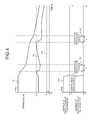
- FIG. 4 is a diagram illustrating an example of the change of the rotation number (rotations per second) of the outdoor fan 4 according to the first embodiment.
- the horizontal axis in FIG. 4 represents time; and
- FIG. 4 illustrates a temperature 101 of the reactor 7, a capacitor ambient temperature 102, and an outside air temperature 103 at an upper portion.
- FIG. 4 illustrates an example where the outside air temperature 103 is T3.
- FIG. 4 illustrates the number of revolutions of the compressor 3 and the number of revolutions of the outdoor fan 4 at a lower portion thereof.
- a revolution number 104 represents the number of revolutions of the compressor 3 in the normal operation mode
- a revolution number 105 represents the normal revolution number of the outdoor fan 4, i.e., the number of revolutions of the outdoor fan 4 in the normal operation mode
- revolution numbers 106 and 107 represent the protective revolution number of the outdoor fan 4, i.e., the number of revolutions of the outdoor fan 4 in the protective operation mode.
- the control unit 10 when the compressor 3 stops rotating, the control unit 10 temporarily stops the outdoor fan 4 and keeps the outdoor fan 4 stopped when the capacitor ambient temperature 102 is less than Tc1.
- the control unit 10 rotates the outdoor fan 4 at the protective revolution number when the capacitor ambient temperature 102 rises to Tc1, and it stops the outdoor fan 4 when the protective operation time becomes t1.
- the control unit 10 rotates the outdoor fan 4 at the protective revolution number when the capacitor ambient temperature 102 rises to Tc1 again, and it stops the outdoor fan 4 when the protective operation time becomes t1.
- the power converter 11 includes a high-heat resistant wide-bandgap semiconductor and is provided in the outdoor device 2.
- the high-heat resistant reactor 7 is placed at the periphery of the outdoor control board 5.
- heat energy from the high-heat resistant wide-bandgap semiconductor and the reactor 7 flows to an electric component of which the heat resistance is lower than those of the wide-bandgap semiconductor and the reactor 7, thereby increasing the temperature of the low-heat resistant electric component.
- the machine room 8 in the outdoor device 2 of air conditioners has been designed to have a reduced size and to have a higher density in order to save energy and space. Accordingly, heat is now more likely to remain in the machine room 8 and the temperature therein tends to rise.
- the electric components can be kept within the allowable temperature range more reliably by stopping the outdoor fan 4 and then comparing the temperature of the capacitor 6 with Tc1 than by comparing the temperature of the capacitor 6 with Tc1 while the outdoor fan 4 operating.
- the outdoor fan 4 is not operated even when the ambient temperature of the capacitor or the like is high. Therefore, the ambient temperature of the capacitor is likely to rise. But, according to the first embodiment, when the compressor 3 stops, the ambient temperature of the capacitor 6 is detected so that, when a power failure occurs or a user trips the circuit breaker and the compressor 3 is thereafter activated again, the outdoor fan 4 is activated to start cooling when the ambient temperature of the capacitor 6 is high.
- the ambient temperature of the capacitor 6 is detected according to the first embodiment, the ambient temperature of an electric component other than the capacitor 6 provided on the outdoor control board 5 can be also detected, and when the temperature is equal to or higher than a threshold, the outdoor fan 4 can be operated in the protective operation mode.
- the outdoor fan 4 when the compressor 3 stops, the outdoor fan 4 is temporarily stopped; and then the outdoor fan 4 is operated for a certain time period when the temperature of the capacitor 6 is equal to or higher than Tc1. Accordingly, the outdoor fan 4 for cooling the electric components is operated for the necessary minimum to prevent the temperature rise of the electric components and thus keeping the temperature of the electric components at a temperature that is lower than the heat-resistant temperature. Therefore, power consumption can be effectively reduced.
- the outdoor fan 4 when the compressor 3 stops, the outdoor fan 4 is temporarily stopped, and then the outdoor fan 4 is operated for a certain time period while the temperature of the capacitor 6 is equal to or higher than Tc1.
- the operation time or the protective operation time of the outdoor fan 4 does not need to be fixed.
- the outdoor fan 4 when the compressor 3 stops, it is also possible that the outdoor fan 4 is temporarily stopped, that the protective operation mode of the outdoor fan 4 may be started when the temperature of the capacitor 6 is equal to or higher than Tc1, and that the protective operation mode is maintained until the temperature of the capacitor 6 becomes equal to or lower than a continued threshold Tc2, which is lower than Tc1.
- the outdoor fan 4 is activated when the temperature of the electric components is high. Therefore, even when a power failure occurs or the user trips the circuit breaker and power is then recovered, a temperature rise of the electric components can be reduced, which effectively prevents both the failure of the electric components and a reduction in the life of the electric components.
- FIG. 5 is a diagram illustrating an example configuration of an air conditioner according to a second embodiment of the present invention.
- the air conditioner according to the second embodiment includes the indoor device 1 and an outdoor device 2a.
- the outdoor device 2a is identical to the outdoor device 2 according to the first embodiment except that the outdoor control board 5 according to the first embodiment is replaced with an outdoor control board 5a.
- the indoor device 1 and the outdoor device 2a are connected to each other with a refrigerant pipe, a power line, and a communication line.
- Constituent elements having functions identical to those described in the first embodiment are denoted by the same reference signs in the first embodiment and redundant descriptions thereof will be omitted. Elements different from the first embodiment are described below.
- the outdoor control board 5a has a supply voltage detector 18 that detects the value of an AC voltage input from the AC power supply 16 or a supply voltage added to the outdoor control board 5 according to the first embodiment.
- An operation associated with the control of the outdoor fan 4 according to the second embodiment is identical to the operation according to the first embodiment.
- a power-failure interruption process is further performed when a power failure occurs.
- the control unit 10 monitors whether a power failure occurs or power is cut off by a user in accordance with a voltage value detected by the supply voltage detector 18, that is, it monitors whether supply of power is stopped, and it interrupts other processes so as to perform the power-failure interruption process when it determines power supply is stopped.
- FIG. 6 is a flowchart illustrating an example of an interrupt processing procedure at a power-failure according to the second embodiment.
- the control unit 10 determines whether the compressor 3 is operating (Step S31). When the compressor 3 is not operating (NO at Step S31), the control unit 10 determines whether the fan operation mode flag is "1" (Step S33). When it is determined that the fan operation mode flag is not "1" (NO at Step S33), the control unit 10 returns to the normal control process for the outdoor fan 4, that is, the process illustrated in FIG. 3 (Step S36), and ends the power-failure interruption process. When the compressor 3 is in operation at Step S31 (YES at Step S31), the control unit 10 stops the compressor 3 (Step S32), and then proceeds to Step S33.
- Step S33 When it is determined at Step S33 that the fan operation mode flag is "1" (YES at Step S33), the control unit 10 stops the outdoor fan 4 (Step S34), sets the fan operation mode flag to "0" (Step S35), and then proceeds to Step S36.
- the compressor 3 and the outdoor fan 4 are stopped, and then the normal control process for the outdoor fan 4 is performed.
- the compressor 3 and the outdoor fan 4 are stopped when a power failure or a power cutoff by the user occurs.
- the voltage smoothed by the capacitor 6 is discharged soon so that all the functions of the outdoor device 2a are stopped. In this case, the ambient temperature of the capacitor 6 may rise.
- the control unit 10 when detecting occurrence of a power failure or a power cutoff by the user, the control unit 10 stops the compressor 3, and then performs the normal control process for the outdoor fan 4. That is, the ambient temperature of the capacitor 6 is detected by using energy remaining in the capacitor 6, and when the ambient temperature of the capacitor 6 exceeds Tc1, the outdoor fan 4 is operated to cool the outdoor control board 5a.
- the compressor 3 is stopped, and then the control process for the outdoor fan 4 that has been described in the first embodiment is performed. Therefore, even when a power failure or a power cutoff by the user occurs, the outdoor fan 4 can cool the outdoor control board 5a.
- FIG. 7 is a diagram illustrating an example configuration of an air conditioner according to a third embodiment of the present invention.
- the air conditioner according to the third embodiment includes the indoor device 1 and an outdoor device 2b.
- the outdoor device 2b is identical to the outdoor device 2 according to the first embodiment except that the outdoor control board 5 according to the first embodiment is replaced with an outdoor control board 5b.
- the indoor device 1 and the outdoor device 2b are connected to each other via a refrigerant pipe, a power line, and a communication line.
- Constituent elements having functions identical to those described in the first embodiment are denoted by the same reference signs in the first embodiment and redundant descriptions thereof will be omitted. Elements different from the first embodiment are described below.
- the outdoor control board 5b is identical to the outdoor control board 5 according to the first embodiment except that the outdoor control board 5b includes a board temperature detector 19 that is a temperature detector to detect the temperature of the surface of the outdoor control board 5b, in place of the capacitor ambient-temperature detector 14 according to the first embodiment.
- the capacitor ambient-temperature detector 14 according to the first embodiment has a limitation on an installation location for detecting the ambient temperature of the capacitor, whereas the board temperature detector 19 can be located anywhere on the outdoor control board 5b. Therefore, according to the third embodiment, wiring can be made shorter and further cost reduction can be achieved, as compared to the case where the capacitor ambient-temperature detector 14 is provided.
- FIG. 8 is a flowchart illustrating an example of a control procedure for the outdoor fan 4 of the air conditioner according to the third embodiment. Steps S1 to S3 and Steps S5 to S22 are identical to those of the first embodiment. According to the third embodiment, Step S23 described below is performed in place of Step S4 of the first embodiment.
- Step S23 the control unit 10 acquires a board temperature detected by the board temperature detector 19, that is, the temperature of the top surface of the outdoor control board 5b from the board temperature detector 19, and determines whether the board temperature is less than a threshold Tp1 (Step S23).
- the control unit 10 ends the process, and when it is determined that the board temperature is equal to or higher than the threshold Tp1 (NO at Step S23), the process proceeds to Step S5.
- the board temperature detector 19 can be also used in place of the capacitor ambient-temperature detector 14 according to the second embodiment.
- the temperature of the outdoor control board 5b is detected instead of detecting the ambient temperature of the capacitor 6. Therefore, effects identical to those of the first embodiment can be achieved, and can achieve further cost reduction than that of the first embodiment.
- the outdoor fan 4 when the compressor 3 is stopped, the outdoor fan 4 is temporarily stopped, and the outdoor fan 4 is operated for a certain time period when the board temperature is equal to or higher than the threshold Tp1.
- the operation time of the outdoor fan 4, that is, the protective operation time may not be set to a certain time period.
- the compressor 3 when the compressor 3 is stopped, it is also possible to configure that the outdoor fan 4 is temporarily stopped, and when the board temperature is equal to or higher than the threshold Tp1, the protective operation mode of the outdoor fan 4 is started, and the board temperature is maintained until the board temperature becomes equal to or lower than a continuous threshold Tp2 that is lower than Tp1.
- FIG. 9 is a diagram illustrating an example configuration of an air conditioner according to a fourth embodiment of the present invention.
- the air conditioner according to the fourth embodiment includes the indoor device 1a and an outdoor device 2c.
- the indoor device 1a is identical to the indoor device 1 according to the third embodiment except that an indoor-device-status display unit 20 that displays the status of the indoor device 1a is added thereto so as to cause a user to observe the status of the indoor device 1a.
- the outdoor device 2c is identical to the outdoor device 2b according to the third embodiment except that the outdoor control board 5b according to the third embodiment is replaced with an outdoor control board 5c.
- the outdoor control board 5c according to the fourth embodiment is identical to the outdoor control board 5b according to the third embodiment except that an outdoor-device-status display unit 21 that displays the status of the outdoor device 2c is added thereto.
- the indoor device 1a and the outdoor device 2c are connected to each other via a refrigerant pipe, a power line, and a communication line.
- Constituent elements having functions identical to those described in the first embodiment are denoted by the same reference signs in the first embodiment and redundant descriptions thereof will be omitted. Elements different from the first embodiment are described below.
- FIG. 10 is a diagram illustrating an example placement of respective constituent elements of the outdoor control board 5c of the outdoor device 2c according to the fourth embodiment.
- FIG. 11 is a diagram illustrating an example configuration of the indoor device 1a according to the fourth embodiment.
- the outdoor-device-status display unit 21 is provided on the outdoor control board 5c. As illustrated in FIG. 11 , the indoor-device-status display unit 20 is disposed at a location that is recognizable to a user of the indoor device 1a.
- the indoor-device-status display unit 20 may be formed of an LED (Light Emitting Diode) that indicates the status of the outdoor device 2c by the number of flickers, a display unit that indicates the status of the outdoor device 2c by a numeral or a symbol provided by an 8-segment display, or may indicate the status of the outdoor device 2c by sound.
- An LED or the like can be used as the outdoor-device-status display unit 21.
- a control procedure for the outdoor fan 4 of the air conditioner is identical to that of the third embodiment.
- the control unit 10 transmits a signal representing the protective operation mode to the indoor device 1a while the protective operation mode is executed. While receiving the signal representing the protective operation mode, the indoor device 1a causes the indoor-device-status display unit 20 to indicate the protective operation mode. Further, while executing the protective operation mode, the control unit 10 instructs the outdoor-device-status display unit 21 to indicate the protective operation mode, so that the outdoor-device-status display unit 21 displays the protective operation mode in response to the instruction.
- the protective operation mode is displayed on both the indoor device 1a and the outdoor control board 5c, it is also possible that the display is made by one of the indoor device 1a and the outdoor control board 5c. Furthermore, the indoor-device-status display unit 20 and the outdoor-device-status display unit 21 can be added to the air conditioner according to the first embodiment or the second embodiment to display the protective operation mode.
- temperature rise of an electric component can be reduced while power consumption is reduced.
Landscapes
- Engineering & Computer Science (AREA)
- Mechanical Engineering (AREA)
- General Engineering & Computer Science (AREA)
- Chemical & Material Sciences (AREA)
- Combustion & Propulsion (AREA)
- Physics & Mathematics (AREA)
- Thermal Sciences (AREA)
- Human Computer Interaction (AREA)
- Signal Processing (AREA)
- Fuzzy Systems (AREA)
- Mathematical Physics (AREA)
- Fluid Mechanics (AREA)
- Air Conditioning Control Device (AREA)
Applications Claiming Priority (1)
| Application Number | Priority Date | Filing Date | Title |
|---|---|---|---|
| JP2014196963A JP6282208B2 (ja) | 2014-09-26 | 2014-09-26 | 室外機および空気調和装置 |
Publications (3)
| Publication Number | Publication Date |
|---|---|
| EP3001114A2 true EP3001114A2 (de) | 2016-03-30 |
| EP3001114A3 EP3001114A3 (de) | 2016-04-20 |
| EP3001114B1 EP3001114B1 (de) | 2022-09-21 |
Family
ID=54065751
Family Applications (1)
| Application Number | Title | Priority Date | Filing Date |
|---|---|---|---|
| EP15183985.9A Active EP3001114B1 (de) | 2014-09-26 | 2015-09-06 | Aussenvorrichtung und klimaanlage |
Country Status (4)
| Country | Link |
|---|---|
| US (1) | US10145596B2 (de) |
| EP (1) | EP3001114B1 (de) |
| JP (1) | JP6282208B2 (de) |
| CN (1) | CN105465909B (de) |
Cited By (4)
| Publication number | Priority date | Publication date | Assignee | Title |
|---|---|---|---|---|
| EP3604942A4 (de) * | 2017-03-28 | 2020-04-01 | Mitsubishi Electric Corporation | Kältekreislaufvorrichtung |
| CN111051780A (zh) * | 2017-08-24 | 2020-04-21 | 三菱电机株式会社 | 空调机 |
| CN113508265A (zh) * | 2019-03-01 | 2021-10-15 | 三菱电机株式会社 | 空调装置的室外机以及空调装置 |
| EP4257887A4 (de) * | 2020-12-01 | 2024-05-29 | Daikin Industries, Ltd. | Klimaanlagensteuerungssystem, servervorrichtung und klimaanlagensteuerungsverfahren |
Families Citing this family (16)
| Publication number | Priority date | Publication date | Assignee | Title |
|---|---|---|---|---|
| CN106016508B (zh) * | 2016-07-22 | 2021-05-25 | 海信家电集团股份有限公司 | 一种空调室外机及空调 |
| CN106247483B (zh) * | 2016-08-12 | 2019-09-03 | 青岛海尔空调器有限总公司 | 电抗器温度的控制方法及装置 |
| CN106288236B (zh) * | 2016-09-30 | 2019-09-20 | Tcl空调器(中山)有限公司 | 空调器压力控制方法和空调器 |
| US10539993B2 (en) * | 2017-03-14 | 2020-01-21 | Microsoft Technology Licensing, Llc | Integrated energy storage systems in computing facilities |
| AU2017408715B2 (en) * | 2017-04-07 | 2020-01-23 | Mitsubishi Electric Corporation | Outdoor unit of air-conditioning apparatus |
| CN111380112B (zh) * | 2018-12-29 | 2021-09-21 | 青岛海尔空调器有限总公司 | 空调器 |
| CN110145837B (zh) * | 2019-04-19 | 2020-11-27 | 青岛海尔空调器有限总公司 | 空调器及其控制方法 |
| CN114364932A (zh) | 2019-09-04 | 2022-04-15 | 大金工业株式会社 | 压缩机单元及冷冻装置 |
| CN112834889B (zh) * | 2019-11-22 | 2024-07-12 | 上海三菱电机·上菱空调机电器有限公司 | 空调室外机中的平滑用电容的寿命预测装置及寿命预测方法 |
| CN111637587B (zh) * | 2020-05-28 | 2021-12-31 | 宁波奥克斯电气股份有限公司 | 压缩机过载保护的控制方法、系统及空调器 |
| CN111964189A (zh) * | 2020-08-26 | 2020-11-20 | 广东美的暖通设备有限公司 | 冷水机的控制方法、装置、冷水机和存储介质 |
| CN113513816B (zh) * | 2021-04-12 | 2022-05-13 | 珠海格力电器股份有限公司 | 目标模块的温度控制方法、装置、电子设备和存储介质 |
| US12169087B2 (en) * | 2021-07-30 | 2024-12-17 | Carrier Corporation | Systems and methods for power control of transport refrigeration systems |
| CN113944978B (zh) * | 2021-11-01 | 2023-03-28 | 宁波奥克斯电气股份有限公司 | 一种空调器的控制方法和空调器 |
| CN117847742A (zh) * | 2024-01-26 | 2024-04-09 | 小米科技(武汉)有限公司 | 一种空调外机的散热处理方法、装置、设备及介质 |
| CN119468396B (zh) * | 2024-12-03 | 2025-10-28 | Tcl空调器(中山)有限公司 | 芯片降温控制方法、装置、空调器及计算机可读存储介质 |
Citations (1)
| Publication number | Priority date | Publication date | Assignee | Title |
|---|---|---|---|---|
| JPH06265199A (ja) | 1993-03-15 | 1994-09-20 | Matsushita Seiko Co Ltd | 空気調和機の送風制御装置 |
Family Cites Families (39)
| Publication number | Priority date | Publication date | Assignee | Title |
|---|---|---|---|---|
| GB1552624A (en) * | 1975-05-13 | 1979-09-19 | Johnson & Starley Ltd | Tri state electrical circuit |
| US4488823A (en) * | 1979-12-31 | 1984-12-18 | Whirlpool Corporation | Selective temperature control system |
| US4557317A (en) * | 1981-02-20 | 1985-12-10 | Harmon Jr Kermit S | Temperature control systems with programmed dead-band ramp and drift features |
| JPS6441752A (en) * | 1987-08-06 | 1989-02-14 | Matsushita Seiko Kk | Device for cooling electrical equipment box of air conditioner |
| JPH037853A (ja) * | 1989-06-05 | 1991-01-16 | Toshiba Corp | 空気調和機 |
| US5239834A (en) * | 1992-07-13 | 1993-08-31 | Travers Richard H | Auxiliary outside air refrigeration system |
| JP3089890B2 (ja) | 1993-03-29 | 2000-09-18 | ダイキン工業株式会社 | 空気調和機の室外ユニット |
| JP3455386B2 (ja) | 1997-01-22 | 2003-10-14 | 三菱電機株式会社 | 空気調和機用インバータ制御回路装置 |
| JP4294112B2 (ja) * | 1998-01-28 | 2009-07-08 | ダイキン工業株式会社 | 室外ファンの制御装置 |
| JP2000046377A (ja) * | 1998-07-27 | 2000-02-18 | Mitsubishi Heavy Ind Ltd | 室外ユニット及び空気調和機 |
| JP2000241004A (ja) * | 1999-02-22 | 2000-09-08 | Hitachi Ltd | 空気調和機の双方向通信方式 |
| JP2001091024A (ja) | 1999-09-20 | 2001-04-06 | Mitsubishi Electric Corp | 冷凍空調装置 |
| US6499960B2 (en) * | 2000-01-28 | 2002-12-31 | Yen Sun Technology Corp. | Control circuit for a heat-dissipation fan |
| CN1148544C (zh) * | 2000-06-09 | 2004-05-05 | 三星电子株式会社 | 空调器的室外风扇控制系统及其控制方法 |
| US7992630B2 (en) * | 2001-03-12 | 2011-08-09 | Davis Energy Group, Inc. | System and method for pre-cooling of buildings |
| JP2002327951A (ja) * | 2001-04-27 | 2002-11-15 | Chofu Seisakusho Co Ltd | 空調機における室外送風ファンのアフターパージ制御装置 |
| US6713942B2 (en) * | 2001-05-23 | 2004-03-30 | Purdue Research Foundation | Piezoelectric device with feedback sensor |
| JP3807353B2 (ja) | 2002-07-31 | 2006-08-09 | ダイキン工業株式会社 | 室外機の電装品ユニットおよび室外機 |
| JP4554151B2 (ja) * | 2002-11-29 | 2010-09-29 | 本田技研工業株式会社 | 燃料電池車両の制御装置 |
| JP2005180800A (ja) | 2003-12-19 | 2005-07-07 | Sharp Corp | 空気調和機 |
| JP4977342B2 (ja) * | 2005-08-01 | 2012-07-18 | 本田技研工業株式会社 | 燃料電池システム及び蓄電装置の充電量調整方法 |
| ES2655254T3 (es) * | 2006-01-16 | 2018-02-19 | Mitsubishi Electric Corporation | Circuito de control de motor y unidad exterior de aparato de aire acondicionado |
| JP4859777B2 (ja) * | 2007-07-27 | 2012-01-25 | 三洋電機株式会社 | 室外ユニット |
| JP4888338B2 (ja) * | 2007-10-31 | 2012-02-29 | ダイキン工業株式会社 | 空気調和機 |
| JP2009138521A (ja) * | 2007-12-03 | 2009-06-25 | Sanden Corp | 電動圧縮機の制御方法 |
| JP2009287843A (ja) * | 2008-05-29 | 2009-12-10 | Daikin Ind Ltd | 室外機及びヒートポンプ装置 |
| JP2010271015A (ja) * | 2009-05-25 | 2010-12-02 | Sharp Corp | 室外機、空気調和機、および室外機制御方法 |
| CN102032206B (zh) * | 2009-09-25 | 2014-08-20 | 鸿富锦精密工业(深圳)有限公司 | 风扇延时控制系统 |
| CN102859858B (zh) * | 2010-02-05 | 2015-04-15 | 松下电器产业株式会社 | 电力变换装置 |
| JP2013096642A (ja) | 2011-11-01 | 2013-05-20 | Panasonic Corp | 冷却装置およびそれを備えた空気調和機 |
| CN103891115B (zh) * | 2011-11-02 | 2017-02-15 | 三菱电机株式会社 | 电力转换装置的驱动装置及电力转换装置的驱动方法 |
| JP5814769B2 (ja) | 2011-12-12 | 2015-11-17 | 三菱電機株式会社 | 室外機 |
| US9947467B2 (en) * | 2012-04-25 | 2018-04-17 | Mjg Innovations, Llc | Protected capacitor system and method |
| US9793049B2 (en) * | 2012-04-25 | 2017-10-17 | Mjg Innovations, Llc | Protected capacitor system and method |
| DE102012106033A1 (de) * | 2012-07-05 | 2014-01-09 | Halla Visteon Climate Control Corporation 95 | Verfahren zum Betreiben eines Inverters eines elektrischen Kältemittelverdichters unter Verwendung von elektrolytischen Zwischenkreis-Kondensatoren |
| JP5721682B2 (ja) * | 2012-10-05 | 2015-05-20 | 三菱電機株式会社 | 電気品モジュールユニット及び空気調和機の室外機 |
| BR112016006158B1 (pt) * | 2013-09-30 | 2022-04-05 | Daikin Industries Ltd. | Dispositivo conversor de potência |
| JP6287073B2 (ja) * | 2013-10-31 | 2018-03-07 | 富士通株式会社 | 冷却装置および冷却方法 |
| DE102015116845A1 (de) * | 2015-10-05 | 2017-04-06 | Kriwan Industrie-Elektronik Gmbh | Maschine mit wenigstens einem Motor und einer Maschinenschutzschaltung |
-
2014
- 2014-09-26 JP JP2014196963A patent/JP6282208B2/ja not_active Expired - Fee Related
-
2015
- 2015-09-04 US US14/845,330 patent/US10145596B2/en not_active Expired - Fee Related
- 2015-09-06 EP EP15183985.9A patent/EP3001114B1/de active Active
- 2015-09-18 CN CN201510598300.9A patent/CN105465909B/zh not_active Expired - Fee Related
Patent Citations (1)
| Publication number | Priority date | Publication date | Assignee | Title |
|---|---|---|---|---|
| JPH06265199A (ja) | 1993-03-15 | 1994-09-20 | Matsushita Seiko Co Ltd | 空気調和機の送風制御装置 |
Cited By (8)
| Publication number | Priority date | Publication date | Assignee | Title |
|---|---|---|---|---|
| EP3604942A4 (de) * | 2017-03-28 | 2020-04-01 | Mitsubishi Electric Corporation | Kältekreislaufvorrichtung |
| CN111051780A (zh) * | 2017-08-24 | 2020-04-21 | 三菱电机株式会社 | 空调机 |
| EP3674621A4 (de) * | 2017-08-24 | 2020-09-02 | Mitsubishi Electric Corporation | Klimaanlage |
| CN111051780B (zh) * | 2017-08-24 | 2021-05-14 | 三菱电机株式会社 | 空调机 |
| CN113508265A (zh) * | 2019-03-01 | 2021-10-15 | 三菱电机株式会社 | 空调装置的室外机以及空调装置 |
| CN113508265B (zh) * | 2019-03-01 | 2022-12-06 | 三菱电机株式会社 | 空调装置的室外机以及空调装置 |
| EP4257887A4 (de) * | 2020-12-01 | 2024-05-29 | Daikin Industries, Ltd. | Klimaanlagensteuerungssystem, servervorrichtung und klimaanlagensteuerungsverfahren |
| US12379120B2 (en) | 2020-12-01 | 2025-08-05 | Daikin Industries. Ltd. | Air conditioner control system, server apparatus and air conditioner control method |
Also Published As
| Publication number | Publication date |
|---|---|
| EP3001114B1 (de) | 2022-09-21 |
| EP3001114A3 (de) | 2016-04-20 |
| JP2016070519A (ja) | 2016-05-09 |
| US10145596B2 (en) | 2018-12-04 |
| US20160091235A1 (en) | 2016-03-31 |
| CN105465909A (zh) | 2016-04-06 |
| JP6282208B2 (ja) | 2018-02-21 |
| CN105465909B (zh) | 2018-11-16 |
Similar Documents
| Publication | Publication Date | Title |
|---|---|---|
| EP3001114B1 (de) | Aussenvorrichtung und klimaanlage | |
| CN1135337C (zh) | 空调器 | |
| JP5289086B2 (ja) | 冷凍サイクル装置 | |
| JP2012135157A (ja) | モータ駆動システム | |
| JP5902521B2 (ja) | 圧縮機モータの制御装置およびこれを搭載した空気調和機 | |
| JP6710338B2 (ja) | 空気調和機 | |
| JP5686754B2 (ja) | 空気調和機 | |
| JP5658969B2 (ja) | 空気調和機 | |
| CN102869931B (zh) | 电动机和系统控制器 | |
| JP5618755B2 (ja) | 電子機器 | |
| US12372285B2 (en) | Device management system for inverter compressor | |
| JP5537378B2 (ja) | 空気調和機 | |
| EP3517851B1 (de) | Klimaanlage | |
| JP5772578B2 (ja) | 空気調和装置 | |
| CN204787044U (zh) | 空调器室内风机的驱动装置和空调器 | |
| CN106165286B (zh) | 致动器驱动装置 | |
| JP5251104B2 (ja) | インバータ装置 | |
| JP2016213978A (ja) | 電源回路及びそれを備える空気調和機 | |
| JP6396679B2 (ja) | 過電流検出回路、空気調和機、サーミスタの取り付け構造、及び電気機器 | |
| JP2009296712A (ja) | インバータ装置 | |
| JP5920709B2 (ja) | 空気調和装置 | |
| JP6173488B2 (ja) | インバータ装置及びインバータ装置を用いた空気調和機 | |
| JPH06213498A (ja) | 空気調和機の制御方法 | |
| JP4389916B2 (ja) | 空調機の制御装置 | |
| JPWO2015033427A1 (ja) | 空気調和装置 |
Legal Events
| Date | Code | Title | Description |
|---|---|---|---|
| PUAL | Search report despatched |
Free format text: ORIGINAL CODE: 0009013 |
|
| PUAI | Public reference made under article 153(3) epc to a published international application that has entered the european phase |
Free format text: ORIGINAL CODE: 0009012 |
|
| AK | Designated contracting states |
Kind code of ref document: A2 Designated state(s): AL AT BE BG CH CY CZ DE DK EE ES FI FR GB GR HR HU IE IS IT LI LT LU LV MC MK MT NL NO PL PT RO RS SE SI SK SM TR |
|
| AX | Request for extension of the european patent |
Extension state: BA ME |
|
| AK | Designated contracting states |
Kind code of ref document: A3 Designated state(s): AL AT BE BG CH CY CZ DE DK EE ES FI FR GB GR HR HU IE IS IT LI LT LU LV MC MK MT NL NO PL PT RO RS SE SI SK SM TR |
|
| AX | Request for extension of the european patent |
Extension state: BA ME |
|
| RIC1 | Information provided on ipc code assigned before grant |
Ipc: F24F 1/06 20110101AFI20160315BHEP Ipc: F24F 1/40 20110101ALI20160315BHEP Ipc: F24F 1/24 20110101ALI20160315BHEP Ipc: F24F 11/00 20060101ALI20160315BHEP |
|
| 17P | Request for examination filed |
Effective date: 20161020 |
|
| RBV | Designated contracting states (corrected) |
Designated state(s): AL AT BE BG CH CY CZ DE DK EE ES FI FR GB GR HR HU IE IS IT LI LT LU LV MC MK MT NL NO PL PT RO RS SE SI SK SM TR |
|
| STAA | Information on the status of an ep patent application or granted ep patent |
Free format text: STATUS: EXAMINATION IS IN PROGRESS |
|
| 17Q | First examination report despatched |
Effective date: 20190722 |
|
| REG | Reference to a national code |
Ref country code: DE Ref legal event code: R079 Ref document number: 602015080877 Country of ref document: DE Free format text: PREVIOUS MAIN CLASS: F24F0001060000 Ipc: F24F0001240000 |
|
| GRAP | Despatch of communication of intention to grant a patent |
Free format text: ORIGINAL CODE: EPIDOSNIGR1 |
|
| STAA | Information on the status of an ep patent application or granted ep patent |
Free format text: STATUS: GRANT OF PATENT IS INTENDED |
|
| RIC1 | Information provided on ipc code assigned before grant |
Ipc: F24F 110/10 20180101ALI20220225BHEP Ipc: F24F 11/77 20180101ALI20220225BHEP Ipc: F24F 11/30 20180101ALI20220225BHEP Ipc: F24F 1/40 20110101ALI20220225BHEP Ipc: F24F 1/24 20110101AFI20220225BHEP |
|
| INTG | Intention to grant announced |
Effective date: 20220325 |
|
| GRAS | Grant fee paid |
Free format text: ORIGINAL CODE: EPIDOSNIGR3 |
|
| GRAA | (expected) grant |
Free format text: ORIGINAL CODE: 0009210 |
|
| STAA | Information on the status of an ep patent application or granted ep patent |
Free format text: STATUS: THE PATENT HAS BEEN GRANTED |
|
| AK | Designated contracting states |
Kind code of ref document: B1 Designated state(s): AL AT BE BG CH CY CZ DE DK EE ES FI FR GB GR HR HU IE IS IT LI LT LU LV MC MK MT NL NO PL PT RO RS SE SI SK SM TR |
|
| REG | Reference to a national code |
Ref country code: GB Ref legal event code: FG4D |
|
| REG | Reference to a national code |
Ref country code: CH Ref legal event code: EP |
|
| REG | Reference to a national code |
Ref country code: DE Ref legal event code: R096 Ref document number: 602015080877 Country of ref document: DE |
|
| REG | Reference to a national code |
Ref country code: IE Ref legal event code: FG4D |
|
| REG | Reference to a national code |
Ref country code: AT Ref legal event code: REF Ref document number: 1520123 Country of ref document: AT Kind code of ref document: T Effective date: 20221015 |
|
| REG | Reference to a national code |
Ref country code: LT Ref legal event code: MG9D |
|
| REG | Reference to a national code |
Ref country code: NL Ref legal event code: MP Effective date: 20220921 |
|
| PG25 | Lapsed in a contracting state [announced via postgrant information from national office to epo] |
Ref country code: SE Free format text: LAPSE BECAUSE OF FAILURE TO SUBMIT A TRANSLATION OF THE DESCRIPTION OR TO PAY THE FEE WITHIN THE PRESCRIBED TIME-LIMIT Effective date: 20220921 Ref country code: RS Free format text: LAPSE BECAUSE OF FAILURE TO SUBMIT A TRANSLATION OF THE DESCRIPTION OR TO PAY THE FEE WITHIN THE PRESCRIBED TIME-LIMIT Effective date: 20220921 Ref country code: NO Free format text: LAPSE BECAUSE OF FAILURE TO SUBMIT A TRANSLATION OF THE DESCRIPTION OR TO PAY THE FEE WITHIN THE PRESCRIBED TIME-LIMIT Effective date: 20221221 Ref country code: LV Free format text: LAPSE BECAUSE OF FAILURE TO SUBMIT A TRANSLATION OF THE DESCRIPTION OR TO PAY THE FEE WITHIN THE PRESCRIBED TIME-LIMIT Effective date: 20220921 Ref country code: LT Free format text: LAPSE BECAUSE OF FAILURE TO SUBMIT A TRANSLATION OF THE DESCRIPTION OR TO PAY THE FEE WITHIN THE PRESCRIBED TIME-LIMIT Effective date: 20220921 Ref country code: FI Free format text: LAPSE BECAUSE OF FAILURE TO SUBMIT A TRANSLATION OF THE DESCRIPTION OR TO PAY THE FEE WITHIN THE PRESCRIBED TIME-LIMIT Effective date: 20220921 |
|
| REG | Reference to a national code |
Ref country code: AT Ref legal event code: MK05 Ref document number: 1520123 Country of ref document: AT Kind code of ref document: T Effective date: 20220921 |
|
| PG25 | Lapsed in a contracting state [announced via postgrant information from national office to epo] |
Ref country code: HR Free format text: LAPSE BECAUSE OF FAILURE TO SUBMIT A TRANSLATION OF THE DESCRIPTION OR TO PAY THE FEE WITHIN THE PRESCRIBED TIME-LIMIT Effective date: 20220921 Ref country code: GR Free format text: LAPSE BECAUSE OF FAILURE TO SUBMIT A TRANSLATION OF THE DESCRIPTION OR TO PAY THE FEE WITHIN THE PRESCRIBED TIME-LIMIT Effective date: 20221222 |
|
| PG25 | Lapsed in a contracting state [announced via postgrant information from national office to epo] |
Ref country code: SM Free format text: LAPSE BECAUSE OF FAILURE TO SUBMIT A TRANSLATION OF THE DESCRIPTION OR TO PAY THE FEE WITHIN THE PRESCRIBED TIME-LIMIT Effective date: 20220921 Ref country code: RO Free format text: LAPSE BECAUSE OF FAILURE TO SUBMIT A TRANSLATION OF THE DESCRIPTION OR TO PAY THE FEE WITHIN THE PRESCRIBED TIME-LIMIT Effective date: 20220921 Ref country code: PT Free format text: LAPSE BECAUSE OF FAILURE TO SUBMIT A TRANSLATION OF THE DESCRIPTION OR TO PAY THE FEE WITHIN THE PRESCRIBED TIME-LIMIT Effective date: 20230123 Ref country code: ES Free format text: LAPSE BECAUSE OF FAILURE TO SUBMIT A TRANSLATION OF THE DESCRIPTION OR TO PAY THE FEE WITHIN THE PRESCRIBED TIME-LIMIT Effective date: 20220921 Ref country code: CZ Free format text: LAPSE BECAUSE OF FAILURE TO SUBMIT A TRANSLATION OF THE DESCRIPTION OR TO PAY THE FEE WITHIN THE PRESCRIBED TIME-LIMIT Effective date: 20220921 Ref country code: AT Free format text: LAPSE BECAUSE OF FAILURE TO SUBMIT A TRANSLATION OF THE DESCRIPTION OR TO PAY THE FEE WITHIN THE PRESCRIBED TIME-LIMIT Effective date: 20220921 |
|
| PG25 | Lapsed in a contracting state [announced via postgrant information from national office to epo] |
Ref country code: SK Free format text: LAPSE BECAUSE OF FAILURE TO SUBMIT A TRANSLATION OF THE DESCRIPTION OR TO PAY THE FEE WITHIN THE PRESCRIBED TIME-LIMIT Effective date: 20220921 Ref country code: PL Free format text: LAPSE BECAUSE OF FAILURE TO SUBMIT A TRANSLATION OF THE DESCRIPTION OR TO PAY THE FEE WITHIN THE PRESCRIBED TIME-LIMIT Effective date: 20220921 Ref country code: IS Free format text: LAPSE BECAUSE OF FAILURE TO SUBMIT A TRANSLATION OF THE DESCRIPTION OR TO PAY THE FEE WITHIN THE PRESCRIBED TIME-LIMIT Effective date: 20230121 Ref country code: EE Free format text: LAPSE BECAUSE OF FAILURE TO SUBMIT A TRANSLATION OF THE DESCRIPTION OR TO PAY THE FEE WITHIN THE PRESCRIBED TIME-LIMIT Effective date: 20220921 |
|
| P01 | Opt-out of the competence of the unified patent court (upc) registered |
Effective date: 20230512 |
|
| REG | Reference to a national code |
Ref country code: DE Ref legal event code: R097 Ref document number: 602015080877 Country of ref document: DE |
|
| PG25 | Lapsed in a contracting state [announced via postgrant information from national office to epo] |
Ref country code: NL Free format text: LAPSE BECAUSE OF FAILURE TO SUBMIT A TRANSLATION OF THE DESCRIPTION OR TO PAY THE FEE WITHIN THE PRESCRIBED TIME-LIMIT Effective date: 20220921 Ref country code: AL Free format text: LAPSE BECAUSE OF FAILURE TO SUBMIT A TRANSLATION OF THE DESCRIPTION OR TO PAY THE FEE WITHIN THE PRESCRIBED TIME-LIMIT Effective date: 20220921 |
|
| PLBE | No opposition filed within time limit |
Free format text: ORIGINAL CODE: 0009261 |
|
| STAA | Information on the status of an ep patent application or granted ep patent |
Free format text: STATUS: NO OPPOSITION FILED WITHIN TIME LIMIT |
|
| PG25 | Lapsed in a contracting state [announced via postgrant information from national office to epo] |
Ref country code: DK Free format text: LAPSE BECAUSE OF FAILURE TO SUBMIT A TRANSLATION OF THE DESCRIPTION OR TO PAY THE FEE WITHIN THE PRESCRIBED TIME-LIMIT Effective date: 20220921 |
|
| 26N | No opposition filed |
Effective date: 20230622 |
|
| PG25 | Lapsed in a contracting state [announced via postgrant information from national office to epo] |
Ref country code: SI Free format text: LAPSE BECAUSE OF FAILURE TO SUBMIT A TRANSLATION OF THE DESCRIPTION OR TO PAY THE FEE WITHIN THE PRESCRIBED TIME-LIMIT Effective date: 20220921 |
|
| REG | Reference to a national code |
Ref country code: CH Ref legal event code: PL |
|
| PG25 | Lapsed in a contracting state [announced via postgrant information from national office to epo] |
Ref country code: LU Free format text: LAPSE BECAUSE OF NON-PAYMENT OF DUE FEES Effective date: 20230906 |
|
| REG | Reference to a national code |
Ref country code: BE Ref legal event code: MM Effective date: 20230930 |
|
| PG25 | Lapsed in a contracting state [announced via postgrant information from national office to epo] |
Ref country code: LU Free format text: LAPSE BECAUSE OF NON-PAYMENT OF DUE FEES Effective date: 20230906 Ref country code: IT Free format text: LAPSE BECAUSE OF FAILURE TO SUBMIT A TRANSLATION OF THE DESCRIPTION OR TO PAY THE FEE WITHIN THE PRESCRIBED TIME-LIMIT Effective date: 20220921 Ref country code: MC Free format text: LAPSE BECAUSE OF FAILURE TO SUBMIT A TRANSLATION OF THE DESCRIPTION OR TO PAY THE FEE WITHIN THE PRESCRIBED TIME-LIMIT Effective date: 20220921 |
|
| REG | Reference to a national code |
Ref country code: IE Ref legal event code: MM4A |
|
| PG25 | Lapsed in a contracting state [announced via postgrant information from national office to epo] |
Ref country code: IE Free format text: LAPSE BECAUSE OF NON-PAYMENT OF DUE FEES Effective date: 20230906 |
|
| PG25 | Lapsed in a contracting state [announced via postgrant information from national office to epo] |
Ref country code: CH Free format text: LAPSE BECAUSE OF NON-PAYMENT OF DUE FEES Effective date: 20230930 |
|
| PG25 | Lapsed in a contracting state [announced via postgrant information from national office to epo] |
Ref country code: IE Free format text: LAPSE BECAUSE OF NON-PAYMENT OF DUE FEES Effective date: 20230906 Ref country code: FR Free format text: LAPSE BECAUSE OF NON-PAYMENT OF DUE FEES Effective date: 20230930 Ref country code: CH Free format text: LAPSE BECAUSE OF NON-PAYMENT OF DUE FEES Effective date: 20230930 |
|
| PG25 | Lapsed in a contracting state [announced via postgrant information from national office to epo] |
Ref country code: BE Free format text: LAPSE BECAUSE OF NON-PAYMENT OF DUE FEES Effective date: 20230930 |
|
| PGFP | Annual fee paid to national office [announced via postgrant information from national office to epo] |
Ref country code: DE Payment date: 20240730 Year of fee payment: 10 |
|
| PGFP | Annual fee paid to national office [announced via postgrant information from national office to epo] |
Ref country code: GB Payment date: 20240801 Year of fee payment: 10 |
|
| PG25 | Lapsed in a contracting state [announced via postgrant information from national office to epo] |
Ref country code: BG Free format text: LAPSE BECAUSE OF FAILURE TO SUBMIT A TRANSLATION OF THE DESCRIPTION OR TO PAY THE FEE WITHIN THE PRESCRIBED TIME-LIMIT Effective date: 20220921 |
|
| PG25 | Lapsed in a contracting state [announced via postgrant information from national office to epo] |
Ref country code: BG Free format text: LAPSE BECAUSE OF FAILURE TO SUBMIT A TRANSLATION OF THE DESCRIPTION OR TO PAY THE FEE WITHIN THE PRESCRIBED TIME-LIMIT Effective date: 20220921 |
|
| PG25 | Lapsed in a contracting state [announced via postgrant information from national office to epo] |
Ref country code: CY Free format text: LAPSE BECAUSE OF FAILURE TO SUBMIT A TRANSLATION OF THE DESCRIPTION OR TO PAY THE FEE WITHIN THE PRESCRIBED TIME-LIMIT; INVALID AB INITIO Effective date: 20150906 |
|
| PG25 | Lapsed in a contracting state [announced via postgrant information from national office to epo] |
Ref country code: HU Free format text: LAPSE BECAUSE OF FAILURE TO SUBMIT A TRANSLATION OF THE DESCRIPTION OR TO PAY THE FEE WITHIN THE PRESCRIBED TIME-LIMIT; INVALID AB INITIO Effective date: 20150906 |
|
| PG25 | Lapsed in a contracting state [announced via postgrant information from national office to epo] |
Ref country code: TR Free format text: LAPSE BECAUSE OF FAILURE TO SUBMIT A TRANSLATION OF THE DESCRIPTION OR TO PAY THE FEE WITHIN THE PRESCRIBED TIME-LIMIT Effective date: 20220921 |