EP3001263B1 - Équipement de connexion pour dispositifs de champ - Google Patents
Équipement de connexion pour dispositifs de champ Download PDFInfo
- Publication number
- EP3001263B1 EP3001263B1 EP15187327.0A EP15187327A EP3001263B1 EP 3001263 B1 EP3001263 B1 EP 3001263B1 EP 15187327 A EP15187327 A EP 15187327A EP 3001263 B1 EP3001263 B1 EP 3001263B1
- Authority
- EP
- European Patent Office
- Prior art keywords
- field device
- terminal port
- communication signal
- control system
- electric power
- Prior art date
- Legal status (The legal status is an assumption and is not a legal conclusion. Google has not performed a legal analysis and makes no representation as to the accuracy of the status listed.)
- Active
Links
Images







Classifications
-
- G—PHYSICS
- G06—COMPUTING OR CALCULATING; COUNTING
- G06F—ELECTRIC DIGITAL DATA PROCESSING
- G06F13/00—Interconnection of, or transfer of information or other signals between, memories, input/output devices or central processing units
- G06F13/38—Information transfer, e.g. on bus
- G06F13/382—Information transfer, e.g. on bus using universal interface adapter
- G06F13/387—Information transfer, e.g. on bus using universal interface adapter for adaptation of different data processing systems to different peripheral devices, e.g. protocol converters for incompatible systems, open system
-
- G—PHYSICS
- G05—CONTROLLING; REGULATING
- G05B—CONTROL OR REGULATING SYSTEMS IN GENERAL; FUNCTIONAL ELEMENTS OF SUCH SYSTEMS; MONITORING OR TESTING ARRANGEMENTS FOR SUCH SYSTEMS OR ELEMENTS
- G05B19/00—Program-control systems
- G05B19/02—Program-control systems electric
- G05B19/04—Program control other than numerical control, i.e. in sequence controllers or logic controllers
- G05B19/042—Program control other than numerical control, i.e. in sequence controllers or logic controllers using digital processors
- G05B19/0423—Input/output
-
- G—PHYSICS
- G06—COMPUTING OR CALCULATING; COUNTING
- G06F—ELECTRIC DIGITAL DATA PROCESSING
- G06F13/00—Interconnection of, or transfer of information or other signals between, memories, input/output devices or central processing units
- G06F13/38—Information transfer, e.g. on bus
- G06F13/42—Bus transfer protocol, e.g. handshake; Synchronisation
- G06F13/4247—Bus transfer protocol, e.g. handshake; Synchronisation on a daisy chain bus
- G06F13/426—Bus transfer protocol, e.g. handshake; Synchronisation on a daisy chain bus using an embedded synchronisation, e.g. Firewire bus, Fibre Channel bus, SSA bus
-
- G—PHYSICS
- G05—CONTROLLING; REGULATING
- G05B—CONTROL OR REGULATING SYSTEMS IN GENERAL; FUNCTIONAL ELEMENTS OF SUCH SYSTEMS; MONITORING OR TESTING ARRANGEMENTS FOR SUCH SYSTEMS OR ELEMENTS
- G05B2219/00—Program-control systems
- G05B2219/20—Pc systems
- G05B2219/25—Pc structure of the system
- G05B2219/25139—Use of separate buscouple interface
-
- G—PHYSICS
- G05—CONTROLLING; REGULATING
- G05B—CONTROL OR REGULATING SYSTEMS IN GENERAL; FUNCTIONAL ELEMENTS OF SUCH SYSTEMS; MONITORING OR TESTING ARRANGEMENTS FOR SUCH SYSTEMS OR ELEMENTS
- G05B2219/00—Program-control systems
- G05B2219/20—Pc systems
- G05B2219/25—Pc structure of the system
- G05B2219/25462—Galvanic separation, galvanic isolation
-
- G—PHYSICS
- G05—CONTROLLING; REGULATING
- G05B—CONTROL OR REGULATING SYSTEMS IN GENERAL; FUNCTIONAL ELEMENTS OF SUCH SYSTEMS; MONITORING OR TESTING ARRANGEMENTS FOR SUCH SYSTEMS OR ELEMENTS
- G05B2219/00—Program-control systems
- G05B2219/30—Nc systems
- G05B2219/34—Director, elements to supervisory
- G05B2219/34421—Termination for each device, enables easy insertion, connection or disconnection
Definitions
- the present invention relates to a connection equipment connected to a field device via a terminal port and to a control system, and, a field device control system for controlling a field device from a control system via a connection equipment.
- a field device control system which comprises a field device (e.g. a measuring device, operation device), a control system for managing and controlling the field device (Control System), and the connection equipment (e.g. Junction Box) connected to the field device and the control system, have been configured conventionally.
- a field device e.g. a measuring device, operation device
- Control System control system for managing and controlling the field device
- connection equipment e.g. Junction Box
- field devices such as sensors and actuators measure or drive processes such as fluid process performed by plant equipment.
- sensors are flowmeter, temperature indicator, and example of actuators is valves.
- Field devices are used in industries to control operation of a process.
- a field device such as a transmitter, is located in the field to measure and transmit a process variable such as pressure, flow or temperature, for example, to control system located in the control room.
- a field device such as a valve controller controls position of a valve based upon a control signal received over the process control loop, or generated internally. Other types of controllers control electric motors or solenoids, for example.
- An operator or computer in the control room is capable of monitoring the process based upon process variables received from transmitters in the field and responsively controlling the process by sending signals to the appropriate field devices.
- an electric power source is normally not set in a field. It is set in a safe place such as the control room that is located far from the field and field devices.
- connection equipment set in the field is configured to receive an electric power signal from a control room via a cable
- the field device set in the field, etc. is configured to receive the electric power signal via the connection equipment.
- a control room houses a marshalling board and a control system. And the control room engineer or control room operator uses the marshaling board in the control room to marshal i.e. check and control a relationship of the field device set in the field and a terminal port of the connection equipment, to which the field device is connected.
- the field engineer or field operator has to inform the control room engineer or control room operator.
- the control room engineer or control room operator has to then make changes to the connections in the marshaling board in the control room. For doing that, the control room engineer or control room operator has to refer to information contained in equipment layouts or segment design layouts.
- FIG.1 A configuration example of the Fieldbus system is presented in Fig.1 .
- the Fieldbus system in Fig. 1 comprises a field device 101, a connection equipment (JB: Junction Box) 100, a terminal board 103, an electric power supply unit PW 104, a control system 105, etc.
- JB Junction Box
- PW electric power supply unit
- the control system 105 performs the marshaling of field devices set in the field and terminal ports in the connection equipment. Specifically, software implemented in the control system 105 performs the marshaling, i.e. the task of checking and controlling a relationship of the field device 101 and a terminal port of JB 100 to which the field device 101 is connected. This allows a physical marshaling board to be omitted.
- a communication signal from the control system 105 and an electric power signal from the electric power supply unit PW 104 are transmitted to JB 100 via a pair of wires in the same cable 102.
- JB 100 transmits the received communication signal and the electric power signal received from the control system 105 to a terminal port assigned by the control system 105.
- the field device 101 receives the communication signal and the electric power signal via the terminal port to which the field device 101 is connected.
- the communication signal and the electric power signal is transmitted from the control system 105 to the terminal port of the JB 100 to which the cable 102 is connected.
- JB 100 transmits the communication signal and the electric power signal to the field device FT107 (101-3)
- JB 100 receives the communication signal and the electric power signal from the cable 102 connected to terminal port 1 and 2.
- JB 100 transmits the communication signal and the electric power signal to the terminal port designated by the control system 105.
- JB 100 transmits the communication signal and the power signal to the terminal port 7, 8 and 9, to which the field device FT107 (101-3) connected.
- the control system has to know the terminal port to which the required destination field device FT107 (101-3) is connected and accordingly, the JB 100 transmits the received communication signal and the electric power signal via the designated terminal port to the destination field device.
- the communication signal has to pass from terminal port 1 and 2, to the terminal port 7, 8 and 9, via the intermediate terminal ports in such configuration. Any fault in any of the terminal ports will cause the communication signal to be interrupted, which is undesirable.
- the control system uses physical address of the field device to address the field devices connected to the JB 100, and the JB 100 lacks any processing logic to avoid the communication signal and electric power signal from passing through multiple terminal ports without isolation.
- Patent No. US8, 374, 094 B2 (Feb.12, 2013 )
- Patent No. US8 , 762 , 618 B2 (Jun.24, 2014 )
- Patent No. US 8,379,546 (Feb 19, 2013 ).
- US 2008/126665 A1 discloses an apparatus and methods to communicatively couple field devices to controllers in a process control system.
- the apparatus includes a first interface configured to receive first information from a field device using a first communication protocol.
- the apparatus also includes a communication processor communicatively coupled to the first interface and configured to encode the first information for communication via a bus using a second communication protocol.
- the apparatus includes a second interface communicatively coupled to the communication processor and the bus and configured to communicate the first information via the bus using the second communication protocol.
- the bus is configured to use the second communication protocol to communicate second information associated with another field device.
- control room engineer can mean engineer, operator, or anybody in charge of the control system in this specification.
- field engineer can mean engineer, operator, or anybody in charge of the field devices in this specification.
- an engineer or operator in the control room has to be in charge of the software which performs marshaling i.e. check and control the relationship between the field device 101 and the terminal port in JB 100. Since the field device 101 and the terminal port in JB 100 are in the field, while the control system is located in a control room far from the field device 101 and JB 100, the field engineer or field operator has to communicate with the control room engineer or control room operator. This is time consuming and more prone to error due to possible miscommunication.
- an engineer in the field is in charge of connecting, disconnecting the field device 101 to or from the terminal port in JB 100, replacing field device 101 and so on.
- the field engineer is responsible for configuring the field device. It is preferable that the engineer in the control room executes the operations related to the field device 101 such as collecting measurements from the field device 101, after the field device 101 is connected to JB 100, instead of having to perform or verify the marshaling. Therefore it is not preferable to marshal the terminal port, to which the field device 101 connected, in the control system 105, but rather, it is preferable to marshal i.e. control and check relationship between the field device 101 and the terminal port in JB 100 in the field itself, without manual intervention.
- the function of the marshaling board is integrated in to software of a specific control system 105, there is a problem that when the control system 105 is modified (for e.g. when the control system is changed to a new control system from a different vendor, when the control system is upgraded to a newer version etc.), the software performing the marshaling also has to be modified. Any change in control system will require change in the software which causes marshaling to be suspended temporarily. During this time, any action by the field engineer or operator in the field i.e. connection, disconnection, replacement etc. of field device 101 to the JB 100 will not be updated to the control system.
- the field engineer or operator may not be immediately informed of the failure of control system or the software in the control system, and all the actions performed by the field engineer or operator, such as connection, disconnection, replacement etc. of field device 101 during the control system or software downtime would need to be performed again, once the control system and/or the software is functional.
- the number of cables can be reduced in the Fieldbus system above, but the communication signal and the electric power signal are transmitted to the terminal port to which the field device is connected, via the terminal ports to which the cable is connected. This means that if any problem happens to the terminal ports to which the cable is connected, or other terminal ports in the JB 100, the communication signal and the electric power signal will not reach the terminal port to which the field device is connected.
- the present invention is invented considering the problems above.
- the purpose of this invention is to provide the connection equipment and the field device control system, which can reduce the overall field device control system cost, can omit the marshaling board, does not require the engineer in the control room or in the field to check, perform, or be in charge of marshaling of the terminal port and the field device, can increase the space available for the control room engineer or operator in the control room, and can limit the influence of electrical short circuit to a certain scope.
- connection equipment as set out in independent claim 1.
- the communication signal from the control system is transmitted along the transmitter/receiver and the processor of the connection equipment independent of the electric power signal from the control system, so even if an electric short circuit in any one terminal port of the connection equipment or field device occurs, the communication signal remains unaffected, and subsequently the processor and transmitter/receiver are also unaffected. In such configuration, the communication signal does not have to go to any terminal port other than the terminal port to which the required field device is connected.
- connection equipment IJB: Isolated Junction Box
- field device control system according to the first embodiment of this invention is explained referring to the figures.
- the field device control system according to this embodiment is shown in Fig. 2 .
- the field device control system according to this embodiment comprises one or more field devices 201, IJB 200, a cable duct 202, a terminal board (TB) 203, Power and Hub unit(PW&HB unit) 204, control systems (205), a maintenance system 208 and one or more input and output modules (IOM) 207.
- IOM input and output modules
- control system 205 is configured to control the one or more field devices 201 via IJB 200, which is connected to the control system 205 by a cable 206, and to provide IJB 200 with an electric power signal via the cable 206.
- the one or more field devices 201 are set for taking measurements and for executing operations in a field such as an industrial plant.
- the field device 201 is connected to IJB 200 via one of the terminal ports 306.
- IJB200 is connected to the control systems 205 and the maintenance system 208 via the cable 206 and to the field device 201 via the terminal port 306. It should be noted that two control systems 205 and one maintenance system 208 are described in Fig.2 but the number of the control systems 205 and the maintenance system 208 is not limited to the number in Fig.2 .
- IJB 200 is configured to transmit and receive the communication signal to / from the control system 205 and the field device 201, and to receive an electric power signal via the cable 206 and to provide the field device 201 with the electric power.
- IJB 200 As IJB 200 is set in the field, IJB 200 is made water-proof, dust proof and intrinsically safe.
- IJB 200 is configured to transmit the communication signal to the field device 201 via the terminal port 306 and to transmit the electric power signal to the field device 201 via the terminal port 306.
- IJB 200 can communicate with the control system 205 with the existing Fieldbus protocol, or other standard protocol such as Ethernet-IP, Profibus-DP protocols. The detailed operation of IJB 200 is described later.
- the cable duct 202 protects the cable 206, connecting the control system 205 which is set in the control room, and IJB 200, which is set in the field.
- the control system 205 is configured to transmit the communication signal for operating the field device 201 and to receive the communication signal from the field device 201.
- the control system 205 is configured to set a configuration of the field device 201.
- the input and output module (IOM) 207 is set for an engineer in the control room to operate the field device 201.
- the maintenance system 208 is configured to maintain the field device 201.
- the input and output module (IOM) 207 is set for an engineer in the control room to maintain the field device 201.
- a field device reference which is used by the control system 205 for identifying the field device 201, is a logical name of the field device 201.
- the logical name is set by an engineer who manages the field device 201 (User Defined Name).
- the field device reference is also called "Application Name”.
- Power and Hub unit (PW & HB unit) 204 generates the electric power signal for providing IJB 200 and the field device 201 with the electric power.
- PW & HB unit Power and Hub unit
- PW & HW unit 204 is preferably set in the safe control room, and provides IJB 200 and the field device 201 with the electric power required for proper functioning of the IJB 200 and the field device 201.
- the electric power signal generated by PW & HB unit 204 is transmitted to IJB 200 via the terminal board 203 and the cable 206. It should be noted that the electric power signal, which is transmitted to IJB 200 and the field device 201, is combined with the communication signal along a pair of wires in the same cable and is transmitted to IJB 200.
- PW & HB unit 204 transmits and receives the communication signal and the electric power signal at a transmission rate suitable for a communication between IJB200 and PW & HB unit 204. And PW & HB unit 204 transmits and receives the communication signal at a transmission rate suitable for a communication between the control system 205 and PW & HB 204. That is, PW & HB unit 204 has a transmission rate adjustment function.
- Hub function in PW & HB unit 204 distributes the communication signal to the appropriate destinations (e.g. IJB 200, control system 205, maintenance system 208 etc.).
- the cable 206 for connecting the terminal board 203 and IJB 200 is usually a standard factory-made cable (e.g. standard instrumentation cables).
- a length of a cable for connecting IJB 200 and the field device 201 is not fixed, as a required length of the cable depends on the place of the field device 201 set in the field.
- short connector cables can be applied between IJB 200 and the field device 201, as a distance between IJB 200 and the field device 201 is usually short.
- the use of standard and easily available cables reduces the overall wiring cost compared to the cost upon using customized or specialized cables.
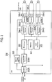
- IJB 200 A configuration of IJB 200 according to this embodiment is explained, referring to Fig.3 to Fig.5 .
- IJB 200 comprises a processor 300, a memory 301, an user interface 302, an electric power adjustor 303 and a transmitter / receiver 304-1 ⁇ 304-4, an isolator 305A, an isolator 305B-1 ⁇ 305B-3, and a terminal port 306-1 ⁇ 306-3.
- the number of the transmitter / receiver 304, the isolator 305B, and the terminal port 306 is showing one of the configuration examples and are changeable.
- the memory 301 is configured to store a table for associating a field device reference of the field device 201 with an identification of the terminal port 306.
- the table in the memory 301 may be configured to include a unique field device reference, which is uniquely allocated to the field device 201, in addition to the field device reference.
- the field device reference is field device name or field device tag for identifying the field device 201 by the engineer managing the control system 205, and may be same as that of another field device 201 in some cases. In such a case, the unique field device reference is used to identify the field device 201 specifically.
- the unique field device reference is a fixed value (e.g. field device ID or field device serial number) and uniquely allocated to the field device 201 before a shipment of the field device 201 by the field device manufacturer. Thus no two field devices 201 will have the same unique field device reference.
- One of the advantages of this invention is that the control system can refer to the field device using the field device reference.
- the table shown in Fig.4 , is configured to manage a relationship of the terminal port identification, a field device type, the field device reference and the unique field device reference.
- the field device type is showing the type of the field device 201, such as a flow meter, a temperature sensor, a pressure control valve, and a flow control valve.
- the field device type specifies if the field device is Analog Input (AI) device, or analog output (AO) device.
- the processor 300 is configured to determine the terminal port 306-1/ 306-2/ 306-3, corresponding to the field device reference included in a communication signal received from the control system 205 based on the table, and to instruct the transmitter/receiver 304 to transmit the communication signal to the terminal port 306 determined.
- the processor 300 retrieves the field device reference from the communication signal received from the control system 205..
- the processor 300 obtains the terminal port identification corresponding to the field device reference included in the communication signal, from the table stored in the memory 301.
- the processor 300 instructs the transmitter/receiver 304 to transmit the communication signal to the determined terminal port 306 in response to the terminal port identification obtained from the memory 301.
- the processor 300 may be configured to determine a transmission destination of the communication signal received from the field device 201 via the terminal port 306, based on the terminal port 306.
- the processor 300 may be configured to determine a transmission destination of the communication signal received from the field device 201 via the terminal port 306, based on the type of request from the control system 205 and the event/message generated by the field device 201.
- the communication signal is transmitted to the control system 205-1, the control system 205-2, or the maintenance system 208 based on the transmission destination determination made by the processor 300.
- the processor 300 may be configured to detect an establishment of a connection of the field device 201 to the terminal port 306 and an occurrence of a disconnection of the field device 201 from the terminal port 306.
- the processor 300 may be configured to detect the establishment of the connection of the field device 201 to the terminal port 306 and the occurrence of the disconnection of the field device 201 from the terminal port 306, when a level of at least one of electric current, electric voltage or electric power at the terminal port 306 is changed.
- the processor 300 may be configured to notify the establishment of the connection of the field device 201 to the terminal port 306 and the occurrence of the disconnection of the field device 201 from the terminal port 306 to the memory 301.
- the memory 301 may be configured to receive a notification regarding the establishment of the connection of the field device 201 to the terminal port 306 and the occurrence of the disconnection of the field device 201 from the terminal port 306, from the processor 300, based on which the table stored in the memory is updated by the processor 300. It means that the processor 300 updates the table stored in the memory 301 based on the establishment of the connection of the field device 201 to the terminal port 306 and the occurrence of the disconnection of the field device 201 from the terminal port 306.
- the memory 301 may be configured to store a history regarding the establishment of the connection of the field device 201 to the terminal port 306 and the occurrence of the disconnection of the field device 201 from the terminal port 306.
- the processor 300 may be configured to report the history stored by the memory 301 to the control system 205, periodically or on demand by a user such as control room engineer, field engineer etc.
- the processor 300 may be configured to communicate with the control system 205 at a first communication speed, and to communicate with the field device 201 at the second communication speed which is different from the first communication speed.
- the communication signal can usually be transmitted and received between the control system 205 / PW&HB unit 204 and IJB 200 with a high data rate.
- the communication speed applied between IJB 200 and the field device 201 depends on a performance of the field device 201 (for e.g. different communication speeds of HART device, FF device, Profibus device etc.). Therefore, the communication speed applied between IJB 200 and the field device 201 is usually slower than that applied between the control system 205 / PW&HB unit 204 and IJB 200.
- the communication speed applied between IJB 200 and the field device 201 may also be equal to the communication speed between the control system 205/ PW&HB unit 204 and IJB 200.
- the processor 300 may execute a protocol conversion on the communication signal received from the control system 205.
- Protocol conversion implies changing a signal format of the communication signal to a recognizable signal format for the field device 201.
- the processor may be configured to retrieve the signal format required by the field device 201 when the field device 201 is connected to the IJB 200 via a terminal port 306.
- the transmitter/receiver 304 is configured to transmit the communication signal received from the processor 300 to the field device 201 via the determined terminal port 306 based on the instruction by the processor 300.
- the transmitter/receiver 304 receives the communication signal via the isolator 305A, and transmits the communication signal to the field device 201 via the terminal port 306 decided by the processor 300.
- the electric power adjustor 303 is configured to adjust a level of an electric power signal to be provided to the field device 201 via the terminal 306 port, based on an input level of an electric power signal received via the cable 206.
- the electric power adjustor 303 may be configured to increase or match a power level of the received electric power signal from an input level of an electric power signal received via the cable to a predetermined power level, which is required for proper functioning of the field device 201 and IJB 200.
- P2 is a total electric power to be output from the electric power adjustor 303.
- P3.1 to p3.n represents the required electric power for each of the n field device 201, n being the number of field device 201 connected to the IJB 200.
- IJB 200 electric power represents the power required by the components within the IJB 200.
- the electric power adjustor 303 ensures the power level of the electric power signal received from the control system 205 via the cable is increased to the level of P2. If the total electric power P2 exceeds a maximum limit, the IJB 200 will automatically detect exceeding power and cut-off the field device 201 requiring more power.
- the electric power adjustor 303 amplifies a power level of the received electric power signal to a power level required for the operation of the field device 201 and IJB 200.
- the isolator 305B is configured to electrically isolate the communication signal to be transmitted to the field device 201 via the terminal port 306 and the electric power signal to be provided to the field device 201 via the terminal port 306, from the other terminal ports 306.
- the isolator 305B receives the electric power signal from the electric power adjustor 303, and passes it to the terminal port 306.
- the isolator 305B receives the communication signal from the transmitter / receiver 304 and transmits it to the terminal port 306.
- the isolator 305B receives the communication signal from the field device 201, and passes it to the transmitter / receiver 304.
- the communication signal can pass bilaterally (two-way) between the IJB 200 and the field device 201 through the isolator while the power signal is sent unilaterally (one-way) from the IJB 200 to the field device 201 through the isolator.
- the isolator 305B electrically isolates the communication signal and the electric power signal from the other terminal ports 306, when the isolator 305B passes the communication signal and the electric power signal via the terminal port 306.
- each isolator 305B has a first isolation element 501, such as a transformer and a second isolation element 502, such as a transformer, a diode.
- transformer is described as the first isolation element 501 and the second isolation element 502, any other electric element that has the same character can be applied as the first isolation element and the second isolation element.
- the communication signal can be passed bilaterally between the transmitter / receiver 304 and the field device 201.
- the communication signal can be passed bilaterally between the transmitter / receiver 304 and the field device 201 via the first isolation element 501 set in the isolator 305B.
- the electric power signal can be passed unilaterally to the field device 201 via the terminal port 306 via the second isolation element 502. Specifically, the electric power signal can be passed only to the field device 201 connected to the terminal port 306 via the second isolation element 502 set in the isolator 305B.
- the specific operation of the isolator 305B is explained below.
- the case when the communication signal is transmitted / received between IJB 200 and the field device 201-1 is explained as an example.
- the communication signal from the transmitter / receiver 304-1 is transmitted to the field device 201-1 via the first isolation element 501-1 set in the isolator 305B-1 and the terminal port 306-1.
- the electric power signal from the electric power adjustor 303 is sent to the field device 201-1 via the second isolation element 502-1 set in the isolator 305B-1 and the terminal port 306-1.
- the electric component, which passes the electric power signal unilateral, such as a transformer or a diode may be applied as the first and second isolation element.
- the communication signal from the field device 201-1 is transmitted to the transmitter / receiver 304-1 via the terminal port 306-1 and the first isolation element 501-1.
- the isolator 305B-1 Due to the configuration of the isolator 305B-1, when an electric short circuit occurs in the field device 201-1 or the terminal port 306-1, the influence of the electric short circuit to the inside of IJB 200 (e.g. the terminal port 306) can be avoided.
- the isolator 305A may be configured to electrically isolate the cable 206 and the terminal port 306.
- the isolator 305A receives the communication signal from the control system 205 and the electric power signal from PW&HB unit 204.
- the isolator 305A separates the communication signal and the electric power signal. Specifically the isolator 305A separates the paths of the communication signal and the electric power signal.
- the isolator 305A passes the electric power signal to the electric power adjustor 303 and the communication signal to the transmitter / receiver 304.
- the user interface 302 is a user interface for an engineer in charge of IJB 200 (field engineer or field operator) to operate IJB 200.
- the engineer in charge of IJB 200 can configure the field device 201 using the user interface 302.
- the user interface 302 comprises a switch, Light emitting diode (LED), LED screens, LCD and so on. And the operation of the user interface 302 can be executed remotely using wireless communication.
- the IJB 200 may further include a mode of input such as keyboard, keypad, touch-screen, stylus, etc.
- the terminal port 306 forwards the communication signal and the electric power signal, passing through the isolator 305B, to the field device 201.
- the terminal port 306 receives the communication signal from the field device 201, and forwards the communication signal to the transmitter / receiver 304.
- the number of the terminal port 306 in IJB is assumed to be around 8.IJB 200 can implement any number of the terminal port 306.
- the number of the terminal port 306 is decided considering cost, size of IJB 200, the electric power and the electric current provided to IJB 200, and so on.
- IJB 200 can communicate with a maintenance terminal using widely applied interfaces, such as USB in the field.
- the control system 205 and / or the maintenance system does not need to execute the maintenance remotely.
- the control system 205 identifies and controls the field device 201 by the field device reference which is set by the engineer in charge of the control system 205. Therefore, when one of the field devices 201 is replaced with another field device 201 having the same field device reference, the control system 205 does not have to be informed of the replacement by the field engineer. The only required procedure during such field device replacement is updating the table in the memory 301 of IJB 200 by the processor 300 in the IJB 200. So the configuration of the control system 205 does not need to be changed, when the field device 201 is replaced due to a failure or for any other reason.
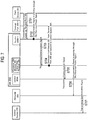
- control system 205 is communicating with the field device 201 connected to terminal port 306-1.
- step 601 the control system 205 transmits the communication signal to PW&HB unit 204.
- the communication signal includes the field device reference of the field device 201-1.
- the PW&HB unit 204 combines the communication signal received from the control system 205 with the electric power signal generated in PW&HB unit 204. By combining, it means that the communication signal and electric power signal are sent along a pair of wires in the same path, for e.g. twisted pair, from the PW&HB unit 204.
- PW&HB unit 204 sends the combined signals to isolator 305A in IJB 200.
- the isolator 305A separates the communication signal and the electric power signal, when the isolator 305A receives the communication signal and the electric power signal.
- separation it means that the communication signal and the electric power signal will not be passed together from the isolator 305A along a pair of wires, but that the path of the communication signal and the electric power signal will be separated at the isolator 305A.
- step 605 the isolator 305A passes the communication signal to the transmitter / receiver 304-4.
- the transmitter / receiver 304-4 transmits the communication signal to the processor 300.
- the processor 300 determines the destination terminal port 306-1 of the communication signal received by referring to the table stored in the memory 301, and decides the destination terminal port 306-1 based on the field device reference included in the communication signal.
- the processor 300 instructs the transmitter / receiver 304-1 to transmit the communication signal to the determined destination terminal port 306-1.
- step 607 the transmitter / receiver 304-1 transmits the communication signal to the isolator 305B-1.
- step 608 the isolator 305A passes the electric power signal to the electric power adjustor 303, in parallel with step 605.
- step 609 the electric power adjustor 303 increases an electric power level of the electric power signal to an electric power level required for operating the field device 201 and IJB 200.
- step 610 the electric power adjustor 303 sends the electric power signal to the isolator 305B-1.
- the isolator 305B-1 combines the communication signal and the electric power signal to be forwarded to the terminal port 306-1, and electrically isolates the communication signal and the electric power signal from the other terminal port 306-2 and 306-3. By combining, it means that the isolator 305B-1 ensures that the path of the communication signal and the electric power signal are combined in the isolator 305B-1.
- step 612 the communication signal and the electric power signal are passed to the field device 201-1 via the isolator 305B-1 and the terminal port 306-1.
- step 701 the field device 201-1 transmits the communication signal to the isolator 305B-1 via the terminal port 306-1.
- the isolator 305B-1 receives the communication signal.
- an electrical short circuit occurs in the field device 201-1, in the terminal port 306-1 or in the isolator 305B-1, any negative impact of the electrical short circuit to IJB 200 and other field devices 201 can be avoided.
- step 703 the isolator 305B-1 passes the communication signal to the transmitter / receiver 304.
- step 704 the transmitter/receiver 304 transmits the communication signal to the processor 300.
- the processor 300 decides the control system 205 based on the terminal port 306-1 from which the communication signal is received and passes the communication signal to transmitter/receiver 304.
- step 705 the transmitter/receiver 304 transmits the communication signal to the isolator 305A.
- step 706 the isolator 305A passes the communication signal to PW&HB unit 204.
- PW&HB unit 204 sends the communication signal to the control system 205.
- step 707 the control system 205 receives the communication signal from PW&HB unit 204. (Operation when the connection of IJB 200 and the field device 201 is established)
- step 801 when the field device 201-1 is connected to IJB 200, IJB 200 identifies the terminal port 306, to which the field device 201-1 is connected.
- IJB 200 tries to obtain at least one or both of the field device reference of the field device 201-1 and the unique field device reference of the field device 201-1.
- IJB 200 can obtain at least one of the field device reference and the unique field device reference from the field device 201-1 (In Step 802, "YES"), IJB 200 updates the field device reference and / or the unique field device reference corresponding to the terminal port 306 in the table stored in the memory 301 ,in step 803.
- IJB 200 requests the control system 205 to input the field device reference of the field device 201-1 and / or the unique field device reference of the field device 201-1.
- the field engineer inputs the field device reference of the field device via the input mode of the IJB 200.
- IJB 200 deletes the field device reference of the field device 201-1 and the unique field device reference of the field device 201-1 managed by the table, when IJB 200 detects an occurrence of a disconnection.
- the processor 300 decides the destination terminal port 306 of the communication signal. This point is different from the conventional Fieldbus system.
- the communication signal is directly transmitted to the terminal port 306 determined, without going through other terminal ports 306.
- the electric power signal and the communication signal are transmitted to the terminal port 306, to which the field device 201 is connected, via the isolator 305B and are electrically isolated from the other terminal ports 306.
- IJB 200 can transmit and receive the communication signal to / from the field device 201, provide the field device 201 with the electric power, and prevent damage to the field devices 201 connected to the other terminal port 306 and to functions or components in IJB 200 as a result of any electric short circuit.
- IJB 200 can perform marshaling i.e. control and check the relationship of the field device 201 and the terminal port 306 it is connected to, thus the control system 205 does not need to manage the terminal port 306 to which the field device 201 is connected. It means that the control system 205 does not have to do marshaling or understand the connection between the field device 201 and the terminal port 306, as it is managed by IJB 200.
- the field device 201 can be addressed by the field device reference, and hence the field device 201 can be managed more effectively.
- the second embodiment according to the present invention is explaining referring to Fig.9 to Fig.12 . It should be noted that the difference from the first embodiment is mainly explained, and the explanation which is the same as the first embodiment is omitted for purposes of clarity alone, and not as a limitation.
- the field device control system according to this embodiment is shown in Fig.9 .
- the field device control system according to this embodiment has a security control unit 600.
- the security control unit 600 is placed between the control system 205 and IJB 200.
- the security control unit 600 may be placed between the control system 205 and the PW&HB unit 204 or between the PW&HB unit 204 and the cable duct 202.
- the security control unit 600 is connected to IJB 200 and to the control system 205 via the cable 206.
- the security control unit 600 checks the communication signal and / or the electric power signal to IJB 200 to confirm whether these signals are from authorized sources or not.
- the sources are any one or more of authorized control systems 205 and maintenance systems 208.
- the security control unit 600 has an encryption and / or an integrity protection procedure.
- the security control unit 600 executes the encryption procedure and / or the integrity protection procedure to the communication signals transmitted and received between the control system 205 and IJB 200.
- the communication signal between the control system 205 and IJB 200 are protected from dangers, such as attacks, hacking and so on.
- the internal structure of the processor 300 is described in Fig.10 .
- the processor 300 comprises of an address resolution module 300-1, a destination determination module 300-2, a protocol conversion module 300-3, and a safety control module 300-4.
- the address resolution module 300-1 resolves a relationship of a field device reference, a unique field device reference and the terminal port 306 to which the field device 201 is connected, by referring to the table in the memory 301.
- the address resolution module 300-1 detects the field device reference transmitted from the control system 205.
- the address resolution module 300-1 may perform an address resolution to identify the unique field device reference corresponding to the field device reference (e.g. device name, device tag) in the communication signal, referring to the table in the memory 301.
- the unique field device reference e.g. device name, device tag
- the destination determination module 300-2 determines the terminal port 306 to which the communication signal from the control system 205 is transmitted and the destination of the communication signal from the field device 201.
- the destination determination module 300-2 communicates with the address resolution module 300-1 in order to resolve the terminal port 306 the communication signal is transmitted.
- the address resolution module 300-1 checks the table in the memory 301 and informs the destination determination module 300-2 of the terminal port 306 correspondent to the field device reference to which communication signal is to be transmitted. Then the destination determination module 300-2 instructs the transmitter / receiver 304 to transmit the communication signal to the terminal port 306 decided.
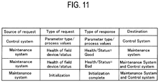
- the destination determination module 300-2 may decide the destination referring the table shown in Fig.11 .
- the destination determination module 300-2 may determine the destination of the communication signal based on a response of "a source of a request", a response of "a type of a request” from the field device 201, or "a type of a response”.
- the source of the request is the source from which the request in the form of communication signal to the field device 201 was generated and transmitted i.e. from the control system 205 or the maintenance system 208.
- the type of the request is for example request for 'Parameter type or process values', 'Health of field device or status', 'Initialization' and so on.
- the destination determination module 300-2 is able to identify the control systems 205 and the maintenance system 208 from the type of the request which was transmitted to the field device 201.
- the type of the response is the response type from the field device 201.
- the type of the response is for example values or responses corresponding to 'parameter type or process values', 'Health or Status', 'Initialization complete'.
- the destination determination module 300-2 may determine the destination of the communication signal from one or more of the event, type of communication signals to the field device 201, or the response generated by the field device 201.
- the destination determination module 300-2 may determine the destination of the communication signal based on a destination list stored in the memory 301.
- the destination list includes the control systems (205-1, 205-2) and the maintenance system 208 or any other destination systems.
- An example of the list in the memory 301 is shown in Fig.11 .
- the destination determination module 300-2 may instruct the transmitter/receiver 304 to transmit the communication signal to the determined destination.
- the protocol conversion module 300-3 converts a protocol applied between the control system 205 or maintenance system 208 and IJB 200 to a protocol applied between IJB 200 and the field device 201.
- the protocol conversion module 300-3 may detect the protocol used in the transmission between the control system 205 or the maintenance system 208 and IJB 200(e.g. protocol A).
- the communication signal received from the control system 205 or the maintenance system 208 is transmitted to the field device 201 through the corresponding terminal port 306 via the transmitter / receiver 304 without any protocol conversion.
- the protocol conversion module 300-3 converts the communication signal from the protocol A to the protocol B. Then, the protocol-converted communication signal is transmitted to the field device 201 through the corresponding terminal port 306 via the transmitter / receiver 304.
- the safety control module 300-4 prevents the electric power of the field device 201 from exceeding a predetermined safety level (Psafe).
- Psafe is a value considering a safe margin from the maximum limit(Pmax)of power.
- the safety control module 300-4 may check the electric power level at each terminal port 306 continuously or at predetermined intervals.
- the safety control module 300-4 may disable the terminal port 306 to which the new field device 201 is connected, may update the table in memory 301 (for example, to remove the entries of field device reference and/or unique field device reference, field device type corresponding to the disabled terminal port) and send a notification signal to the user interface 302 in IJB and / or the control system 205 indicating that the respective terminal port 306 has been disabled, for safety reasons.
- a safety limit Psafe
- the disabled terminal port 306 would not be made available for use until that field device 201 is disconnected. Subsequently no further communication signal from the control system 205 can be transmitted to that field device 201.
- IJB 200 implemented in "Junction Box", is explained. IJB 200 is not required to be a form of "box". It should be noted that IJB 200 can be achieved by equipment which connects the control system 205 via the cable 206 and connects the field device 201 via the terminal port 306.
- the communication signal from the control system 205 and the electric power signal from PW & HB unit 204 are combined in the same cable 206 and are transmitted to IJB 200, are explained. It should be noted that the communication signal and the power signal can be transmitted by different cables.
- IJB 200 may be configured to allow peer to peer communication between the field devices 201 rather than broadcasting the communication signals to the field devices 201(e.g. scan or cyclic broadcasting).
- the communication signal is transmitted and received between the control system 205 and the field device 201 in the same way as described in the embodiments above.
- connection equipment and the field device control system can reduce the overall operational cost, can omit the marshaling board, is not necessary to manage the terminal port to which the field device is connected from the control room , and can limit the influence of electrical short circuit to a certain scope.
Landscapes
- Engineering & Computer Science (AREA)
- Theoretical Computer Science (AREA)
- Physics & Mathematics (AREA)
- General Physics & Mathematics (AREA)
- General Engineering & Computer Science (AREA)
- Automation & Control Theory (AREA)
- Programmable Controllers (AREA)
- Arrangements For Transmission Of Measured Signals (AREA)
Claims (11)
- Équipement de connexion (200) connecté à un dispositif de terrain (201) via un d'une pluralité de ports de terminal (306), le dispositif de terrain (201) étant commandé par un système de commande (205) connecté à l'équipement de connexion (200), l'équipement de connexion (200) comprenant :au moins un émetteur/récepteur (304) configuré pour recevoir un premier signal de communication en provenance du système de commande (205), le premier signal de communication comprenant une référence de dispositif de terrain du dispositif de terrain (201) ;une mémoire (301) configurée pour stocker une table pour associer la référence de dispositif de terrain du dispositif de terrain (201) à une identification d'un de la pluralité de ports de terminal (306) auquel le dispositif de terrain (201) est connecté ;un processeur (300) configuré pour déterminer un port de terminal (306) parmi la pluralité de ports de terminal (306) sur la base de la référence de dispositif de terrain incluse dans le premier signal de communication reçu, et pour ordonner à l'au moins un émetteur/récepteur (304) de transmettre le premier signal de communication reçu au dispositif de terrain (201) via le port de terminal déterminé (306) ;un ajusteur de puissance électrique (303) configuré pour ajuster un niveau d'un signal de puissance électrique à fournir au dispositif de terrain (201) via le port de terminal déterminé (306) sur la base d'un niveau d'entrée d'un signal de puissance électrique reçu du système de commande (205) via un câble ; etau moins un isolateur (305B) configuré pour transmettre le signal de puissance électrique et le premier signal de communication via le port de terminal déterminé (306), l'au moins un isolateur (305B) comprenant :un premier élément d'isolation (501) configuré pour transmettre le premier signal de communication de l'au moins un émetteur/récepteur (304) au dispositif de terrain (201) ; etun second élément d'isolation (502) configuré pour transmettre le signal de puissance électrique provenant de l'ajusteur de puissance électrique (303).
- Équipement de connexion (200) selon la revendication 1, dans lequel
le processeur (300) est configuré pour déterminer une destination de transmission d'un second signal de communication reçu du dispositif de terrain (201) via le port de terminal (306), sur la base d'un ou de plusieurs de la pluralité des ports de terminal (306), d'une source du premier signal de communication transmis vers le dispositif de terrain (201), d'un type d'une demande transmise au dispositif de terrain (201), ou d'un type d'une réponse générée par le dispositif de terrain (201). - Équipement de connexion (200) selon la revendication 1, dans lequel
le processeur (300) est configuré pour détecter un établissement d'une connexion du dispositif de terrain (201) au port de terminal (306) et une apparition d'une déconnexion du dispositif de terrain (201) du port de terminal (306) ; et
la mémoire (301) est configurée pour recevoir une instruction en, provenance du processeur (300) pour mettre à jour la table stockée selon l'établissement de la connexion et l'apparition de la déconnexion détectés par le processeur (300). - Équipement de connexion (200) selon la revendication 3, dans lequel
le processeur (300) est configuré pour détecter l'établissement de la connexion et l'apparition de la déconnexion lorsqu'un niveau d'au moins un d'un courant électrique, d'une tension électrique ou d'une puissance électrique au niveau du port de terminal (306) est changé. - Équipement de connexion (200) selon la revendication 3, dans lequel
la mémoire (301) est configurée pour stocker un historique de l'établissement de la connexion et de l'apparition de la déconnexion ; et
le processeur (300) est configuré pour rapporter l'historique au système de commande (205). - Équipement de connexion (200) selon la revendication 1, dans lequel
le processeur (300) est configuré pour communiquer avec le système de commande (205) à une première vitesse de communication, et pour communiquer avec le dispositif de terrain (201) à la seconde vitesse de communication qui est différente de la première vitesse de communication. - Équipement de connexion (200) selon la revendication 1, dans lequel
la mémoire (301) est configurée pour gérer une référence de dispositif de terrain unique, qui est attribuée uniquement au dispositif de terrain (201) avant une expédition du dispositif de terrain (201), en plus de la référence de dispositif de terrain dans la table. - Équipement de connexion (200) selon la revendication 1, dans lequel
l'ajusteur de puissance électrique (303) est configuré pour augmenter un niveau de puissance du signal de puissance électrique reçu à un niveau de puissance prédéterminé, qui est requis par le dispositif de terrain (201). - Équipement de connexion (200) selon la revendication 1, dans lequel
l'au moins un isolateur (305B) est configuré pour isoler électriquement le câble et le port de terminal (306). - Équipement de connexion (200) selon la revendication 1, dans lequel le processeur (300) comprend :un module de résolution d'adresse (300-1) configuré pour résoudre une relation entre une référence de dispositif de terrain du dispositif de terrain (201) et une identification du port de terminal (306) auquel le dispositif de terrain (201) est connecté, en se référant à une table stockée dans la mémoire (301) de l'équipement de connexion (200) ;un module de détermination de destination (300-2) configuré pour déterminer le port de terminal (306) auquel le premier signal de communication en provenance du système de commande (205) doit être transmis, en réponse à une communication avec le module de résolution d'adresse (300-1), sur la base de la référence de dispositif de terrain incluse dans le premier signal de communication ; etun module de conversion de protocole (300-3) configuré pour convertir un protocole appliqué au premier signal de communication entre le système de commande (205) et l'équipement de connexion (200) en un protocole appliqué au premier signal de communication entre l'équipement de connexion (200) et le dispositif de terrain (201).
- Équipement de connexion (200) selon la revendication 10, dans lequel le processeur (300) comprend en outre :un module de commande de sécurité (300-4) configuré pour désactiver le port de terminal (306) auquel le dispositif de terrain (201) est connecté, lorsque le dispositif de terrain (201) est connecté au port de terminal (306) et qu'il est déterminé qu'une puissance électrique vers le port de terminal (306) s'approche d'un niveau de sécurité prédéterminé.
Applications Claiming Priority (1)
| Application Number | Priority Date | Filing Date | Title |
|---|---|---|---|
| US14/500,078 US9798690B2 (en) | 2014-09-29 | 2014-09-29 | Connection equipment and a field device control system |
Publications (3)
| Publication Number | Publication Date |
|---|---|
| EP3001263A2 EP3001263A2 (fr) | 2016-03-30 |
| EP3001263A3 EP3001263A3 (fr) | 2016-06-29 |
| EP3001263B1 true EP3001263B1 (fr) | 2018-03-14 |
Family
ID=54291027
Family Applications (1)
| Application Number | Title | Priority Date | Filing Date |
|---|---|---|---|
| EP15187327.0A Active EP3001263B1 (fr) | 2014-09-29 | 2015-09-29 | Équipement de connexion pour dispositifs de champ |
Country Status (3)
| Country | Link |
|---|---|
| US (1) | US9798690B2 (fr) |
| EP (1) | EP3001263B1 (fr) |
| JP (1) | JP6245132B2 (fr) |
Families Citing this family (15)
| Publication number | Priority date | Publication date | Assignee | Title |
|---|---|---|---|---|
| JP6248901B2 (ja) * | 2014-11-13 | 2017-12-20 | 横河電機株式会社 | 入出力装置 |
| DE102014016819A1 (de) * | 2014-11-14 | 2016-05-19 | Abb Technology Ag | Verfahren und Einrichtung zur Verwaltung und Konfiguration von Feldgeräten einer Automatisierungsanlage |
| US9769548B2 (en) * | 2015-07-15 | 2017-09-19 | Honeywell International Inc. | Wireless device for capturing stranded data on field devices |
| US10671038B2 (en) * | 2016-07-15 | 2020-06-02 | Fisher-Rosemount Systems, Inc. | Architecture-independent process control |
| US10311009B2 (en) * | 2016-10-24 | 2019-06-04 | Fisher-Rosemount Systems, Inc. | Apparatus and methods for communicatively coupling field devices to controllers in a process control system using a distributed marshaling architecture |
| CN111989626B (zh) | 2018-01-31 | 2024-01-30 | 帕克-汉尼芬公司 | 用于控制阀歧管的系统和方法 |
| TWI665556B (zh) * | 2018-05-11 | 2019-07-11 | 緯穎科技服務股份有限公司 | 輸入輸出介面配置的方法、可配置輸入輸出介面的裝置及控制系統 |
| US11531381B2 (en) * | 2018-09-28 | 2022-12-20 | Fisher-Rosemount Systems, Inc. | Smart functionality for discrete field devices and signals |
| US11106611B2 (en) * | 2019-12-10 | 2021-08-31 | Baker Hughes Oilfield Operations Llc | Control system migration using interface card |
| EP4568210A3 (fr) | 2021-02-23 | 2025-07-23 | Phoenix Contact Development and Manufacturing, Inc. | Commutateur de champ apl a detection automatique de protocole |
| KR102558983B1 (ko) * | 2021-08-19 | 2023-07-24 | 한국전력기술 주식회사 | 사이버 보안을 위한 통신격리기, 및 통신격리방법 |
| EP4290818A1 (fr) * | 2022-06-10 | 2023-12-13 | Vestas Wind Systems A/S | Procédé de mise en place de composants de réseau dans un réseau de communication d'éolienne |
| US12218775B2 (en) * | 2022-12-19 | 2025-02-04 | Rosemount Inc. | Advanced physical layer (APL) adapter for legacy field devices |
| US12592559B2 (en) | 2022-12-19 | 2026-03-31 | Rosemount Inc. | Field device current limiting |
| US12493315B2 (en) | 2024-04-30 | 2025-12-09 | Rosemount Inc. | Ethernet-APL field device having reduced energy consumption |
Family Cites Families (10)
| Publication number | Priority date | Publication date | Assignee | Title |
|---|---|---|---|---|
| US7536548B1 (en) * | 2002-06-04 | 2009-05-19 | Rockwell Automation Technologies, Inc. | System and methodology providing multi-tier-security for network data exchange with industrial control components |
| JP4489570B2 (ja) | 2004-12-02 | 2010-06-23 | 東芝三菱電機産業システム株式会社 | 入出力制御装置 |
| US8332567B2 (en) * | 2006-09-19 | 2012-12-11 | Fisher-Rosemount Systems, Inc. | Apparatus and methods to communicatively couple field devices to controllers in a process control system |
| CN101197016A (zh) * | 2006-12-08 | 2008-06-11 | 鸿富锦精密工业(深圳)有限公司 | 分批次并行作业处理装置及方法 |
| JP5274769B2 (ja) * | 2006-12-25 | 2013-08-28 | 株式会社東芝 | 機器使用状況管理システム |
| US8374094B2 (en) | 2008-12-11 | 2013-02-12 | Fisher-Rosemount Systems, Inc | Methods and systems to verify a communication path between a field device and a process controller in a process control system |
| US8977851B2 (en) | 2009-01-21 | 2015-03-10 | Fisher-Rosemount Systems, Inc. | Removable security modules and related methods |
| US9285799B2 (en) | 2009-11-23 | 2016-03-15 | Fisher-Rosemount Systems, Inc. | Methods and apparatus to dynamically display data associated with a process control system |
| US8379546B2 (en) | 2010-04-06 | 2013-02-19 | Fisher-Rosemount Systems, Inc. | Methods and apparatus to communicatively couple a portable device to process control devices in a process control system |
| CN104995574B (zh) | 2013-03-12 | 2017-10-13 | 沙特阿拉伯石油公司 | 油田过程控制系统 |
-
2014
- 2014-09-29 US US14/500,078 patent/US9798690B2/en not_active Expired - Fee Related
- 2014-10-16 JP JP2014211626A patent/JP6245132B2/ja not_active Expired - Fee Related
-
2015
- 2015-09-29 EP EP15187327.0A patent/EP3001263B1/fr active Active
Non-Patent Citations (1)
| Title |
|---|
| None * |
Also Published As
| Publication number | Publication date |
|---|---|
| US20160092386A1 (en) | 2016-03-31 |
| JP6245132B2 (ja) | 2017-12-13 |
| EP3001263A3 (fr) | 2016-06-29 |
| JP2016071828A (ja) | 2016-05-09 |
| EP3001263A2 (fr) | 2016-03-30 |
| US9798690B2 (en) | 2017-10-24 |
Similar Documents
| Publication | Publication Date | Title |
|---|---|---|
| EP3001263B1 (fr) | Équipement de connexion pour dispositifs de champ | |
| US7848827B2 (en) | Apparatus, system, and method for wireless diagnostics | |
| US9869987B2 (en) | Field bus system with industrial measurement device having automonous control operation | |
| US10503668B2 (en) | Intelligent field input/output (I/O) terminal for industrial control and related system and method | |
| US10678592B2 (en) | Process control system | |
| US9946613B2 (en) | Instrumentation system and method for maintaining the same | |
| CN104678946B (zh) | I/o 模块以及过程控制系统 | |
| JP2014146087A (ja) | 監視制御システム | |
| US12316469B2 (en) | Secondary control for de-energizing safety field devices with digital protocols | |
| CN107562021B (zh) | 预配置或配置工业自动化环境中操作的设备的系统和方法 | |
| US10715396B2 (en) | Support apparatus, non-transitory computer readable recording medium and setting method | |
| CN103970051A (zh) | 显示装置 | |
| CN102880167A (zh) | 现场通信系统 | |
| US11550298B2 (en) | Method for operating an automation technology facility | |
| WO2014042636A1 (fr) | Inspection d'intrusion de paquets dans un réseau de commandes industriel | |
| JP2006065385A (ja) | フィールド機器 | |
| CN115079595A (zh) | 输入和/或输出模块与具有上级控制装置的现场总线的连接 | |
| JP5894859B2 (ja) | 生産管理システム、生産管理方法および生産管理プログラム | |
| JP2013182392A (ja) | デバイスコントローラ | |
| CN111752236B (zh) | 模块安装方法 | |
| CA3029002C (fr) | Systèmes et méthodes pour fournir des dispositifs de configuration fonctionnant dans des environnements d’automatisation industriels | |
| JP6794708B2 (ja) | 制御装置、制御システム及び制御方法 | |
| JP2015061232A (ja) | コントローラおよび冗長コントローラ | |
| JP2018026674A (ja) | ゲートウェイ装置、異常監視システム、異常監視プログラム、及び異常監視方法 | |
| CN107885687A (zh) | 一种用于将fru模块连接到i2c总线的接口 |
Legal Events
| Date | Code | Title | Description |
|---|---|---|---|
| PUAI | Public reference made under article 153(3) epc to a published international application that has entered the european phase |
Free format text: ORIGINAL CODE: 0009012 |
|
| AK | Designated contracting states |
Kind code of ref document: A2 Designated state(s): AL AT BE BG CH CY CZ DE DK EE ES FI FR GB GR HR HU IE IS IT LI LT LU LV MC MK MT NL NO PL PT RO RS SE SI SK SM TR |
|
| AX | Request for extension of the european patent |
Extension state: BA ME |
|
| PUAL | Search report despatched |
Free format text: ORIGINAL CODE: 0009013 |
|
| AK | Designated contracting states |
Kind code of ref document: A3 Designated state(s): AL AT BE BG CH CY CZ DE DK EE ES FI FR GB GR HR HU IE IS IT LI LT LU LV MC MK MT NL NO PL PT RO RS SE SI SK SM TR |
|
| AX | Request for extension of the european patent |
Extension state: BA ME |
|
| RIC1 | Information provided on ipc code assigned before grant |
Ipc: G05B 19/042 20060101AFI20160525BHEP Ipc: G06F 13/42 20060101ALI20160525BHEP Ipc: G06F 13/38 20060101ALI20160525BHEP |
|
| 17P | Request for examination filed |
Effective date: 20161214 |
|
| RBV | Designated contracting states (corrected) |
Designated state(s): AL AT BE BG CH CY CZ DE DK EE ES FI FR GB GR HR HU IE IS IT LI LT LU LV MC MK MT NL NO PL PT RO RS SE SI SK SM TR |
|
| 17Q | First examination report despatched |
Effective date: 20170208 |
|
| GRAP | Despatch of communication of intention to grant a patent |
Free format text: ORIGINAL CODE: EPIDOSNIGR1 |
|
| INTG | Intention to grant announced |
Effective date: 20171012 |
|
| GRAS | Grant fee paid |
Free format text: ORIGINAL CODE: EPIDOSNIGR3 |
|
| GRAA | (expected) grant |
Free format text: ORIGINAL CODE: 0009210 |
|
| AK | Designated contracting states |
Kind code of ref document: B1 Designated state(s): AL AT BE BG CH CY CZ DE DK EE ES FI FR GB GR HR HU IE IS IT LI LT LU LV MC MK MT NL NO PL PT RO RS SE SI SK SM TR |
|
| REG | Reference to a national code |
Ref country code: GB Ref legal event code: FG4D |
|
| REG | Reference to a national code |
Ref country code: CH Ref legal event code: EP Ref country code: AT Ref legal event code: REF Ref document number: 979473 Country of ref document: AT Kind code of ref document: T Effective date: 20180315 |
|
| REG | Reference to a national code |
Ref country code: IE Ref legal event code: FG4D |
|
| REG | Reference to a national code |
Ref country code: DE Ref legal event code: R096 Ref document number: 602015008699 Country of ref document: DE |
|
| REG | Reference to a national code |
Ref country code: NL Ref legal event code: MP Effective date: 20180314 |
|
| REG | Reference to a national code |
Ref country code: LT Ref legal event code: MG4D |
|
| PG25 | Lapsed in a contracting state [announced via postgrant information from national office to epo] |
Ref country code: LT Free format text: LAPSE BECAUSE OF FAILURE TO SUBMIT A TRANSLATION OF THE DESCRIPTION OR TO PAY THE FEE WITHIN THE PRESCRIBED TIME-LIMIT Effective date: 20180314 Ref country code: NO Free format text: LAPSE BECAUSE OF FAILURE TO SUBMIT A TRANSLATION OF THE DESCRIPTION OR TO PAY THE FEE WITHIN THE PRESCRIBED TIME-LIMIT Effective date: 20180614 Ref country code: HR Free format text: LAPSE BECAUSE OF FAILURE TO SUBMIT A TRANSLATION OF THE DESCRIPTION OR TO PAY THE FEE WITHIN THE PRESCRIBED TIME-LIMIT Effective date: 20180314 Ref country code: FI Free format text: LAPSE BECAUSE OF FAILURE TO SUBMIT A TRANSLATION OF THE DESCRIPTION OR TO PAY THE FEE WITHIN THE PRESCRIBED TIME-LIMIT Effective date: 20180314 Ref country code: CY Free format text: LAPSE BECAUSE OF FAILURE TO SUBMIT A TRANSLATION OF THE DESCRIPTION OR TO PAY THE FEE WITHIN THE PRESCRIBED TIME-LIMIT Effective date: 20180314 |
|
| REG | Reference to a national code |
Ref country code: FR Ref legal event code: PLFP Year of fee payment: 4 |
|
| REG | Reference to a national code |
Ref country code: AT Ref legal event code: MK05 Ref document number: 979473 Country of ref document: AT Kind code of ref document: T Effective date: 20180314 |
|
| PG25 | Lapsed in a contracting state [announced via postgrant information from national office to epo] |
Ref country code: SE Free format text: LAPSE BECAUSE OF FAILURE TO SUBMIT A TRANSLATION OF THE DESCRIPTION OR TO PAY THE FEE WITHIN THE PRESCRIBED TIME-LIMIT Effective date: 20180314 Ref country code: LV Free format text: LAPSE BECAUSE OF FAILURE TO SUBMIT A TRANSLATION OF THE DESCRIPTION OR TO PAY THE FEE WITHIN THE PRESCRIBED TIME-LIMIT Effective date: 20180314 Ref country code: GR Free format text: LAPSE BECAUSE OF FAILURE TO SUBMIT A TRANSLATION OF THE DESCRIPTION OR TO PAY THE FEE WITHIN THE PRESCRIBED TIME-LIMIT Effective date: 20180615 Ref country code: BG Free format text: LAPSE BECAUSE OF FAILURE TO SUBMIT A TRANSLATION OF THE DESCRIPTION OR TO PAY THE FEE WITHIN THE PRESCRIBED TIME-LIMIT Effective date: 20180614 Ref country code: RS Free format text: LAPSE BECAUSE OF FAILURE TO SUBMIT A TRANSLATION OF THE DESCRIPTION OR TO PAY THE FEE WITHIN THE PRESCRIBED TIME-LIMIT Effective date: 20180314 |
|
| PG25 | Lapsed in a contracting state [announced via postgrant information from national office to epo] |
Ref country code: IT Free format text: LAPSE BECAUSE OF FAILURE TO SUBMIT A TRANSLATION OF THE DESCRIPTION OR TO PAY THE FEE WITHIN THE PRESCRIBED TIME-LIMIT Effective date: 20180314 Ref country code: AL Free format text: LAPSE BECAUSE OF FAILURE TO SUBMIT A TRANSLATION OF THE DESCRIPTION OR TO PAY THE FEE WITHIN THE PRESCRIBED TIME-LIMIT Effective date: 20180314 Ref country code: PL Free format text: LAPSE BECAUSE OF FAILURE TO SUBMIT A TRANSLATION OF THE DESCRIPTION OR TO PAY THE FEE WITHIN THE PRESCRIBED TIME-LIMIT Effective date: 20180314 Ref country code: EE Free format text: LAPSE BECAUSE OF FAILURE TO SUBMIT A TRANSLATION OF THE DESCRIPTION OR TO PAY THE FEE WITHIN THE PRESCRIBED TIME-LIMIT Effective date: 20180314 Ref country code: RO Free format text: LAPSE BECAUSE OF FAILURE TO SUBMIT A TRANSLATION OF THE DESCRIPTION OR TO PAY THE FEE WITHIN THE PRESCRIBED TIME-LIMIT Effective date: 20180314 Ref country code: NL Free format text: LAPSE BECAUSE OF FAILURE TO SUBMIT A TRANSLATION OF THE DESCRIPTION OR TO PAY THE FEE WITHIN THE PRESCRIBED TIME-LIMIT Effective date: 20180314 Ref country code: ES Free format text: LAPSE BECAUSE OF FAILURE TO SUBMIT A TRANSLATION OF THE DESCRIPTION OR TO PAY THE FEE WITHIN THE PRESCRIBED TIME-LIMIT Effective date: 20180314 |
|
| PGFP | Annual fee paid to national office [announced via postgrant information from national office to epo] |
Ref country code: IT Payment date: 20180930 Year of fee payment: 4 |
|
| PG25 | Lapsed in a contracting state [announced via postgrant information from national office to epo] |
Ref country code: SM Free format text: LAPSE BECAUSE OF FAILURE TO SUBMIT A TRANSLATION OF THE DESCRIPTION OR TO PAY THE FEE WITHIN THE PRESCRIBED TIME-LIMIT Effective date: 20180314 Ref country code: CZ Free format text: LAPSE BECAUSE OF FAILURE TO SUBMIT A TRANSLATION OF THE DESCRIPTION OR TO PAY THE FEE WITHIN THE PRESCRIBED TIME-LIMIT Effective date: 20180314 Ref country code: SK Free format text: LAPSE BECAUSE OF FAILURE TO SUBMIT A TRANSLATION OF THE DESCRIPTION OR TO PAY THE FEE WITHIN THE PRESCRIBED TIME-LIMIT Effective date: 20180314 Ref country code: AT Free format text: LAPSE BECAUSE OF FAILURE TO SUBMIT A TRANSLATION OF THE DESCRIPTION OR TO PAY THE FEE WITHIN THE PRESCRIBED TIME-LIMIT Effective date: 20180314 |
|
| REG | Reference to a national code |
Ref country code: DE Ref legal event code: R097 Ref document number: 602015008699 Country of ref document: DE |
|
| PG25 | Lapsed in a contracting state [announced via postgrant information from national office to epo] |
Ref country code: PT Free format text: LAPSE BECAUSE OF FAILURE TO SUBMIT A TRANSLATION OF THE DESCRIPTION OR TO PAY THE FEE WITHIN THE PRESCRIBED TIME-LIMIT Effective date: 20180716 |
|
| PLBE | No opposition filed within time limit |
Free format text: ORIGINAL CODE: 0009261 |
|
| STAA | Information on the status of an ep patent application or granted ep patent |
Free format text: STATUS: NO OPPOSITION FILED WITHIN TIME LIMIT |
|
| PG25 | Lapsed in a contracting state [announced via postgrant information from national office to epo] |
Ref country code: DK Free format text: LAPSE BECAUSE OF FAILURE TO SUBMIT A TRANSLATION OF THE DESCRIPTION OR TO PAY THE FEE WITHIN THE PRESCRIBED TIME-LIMIT Effective date: 20180314 |
|
| 26N | No opposition filed |
Effective date: 20181217 |
|
| PG25 | Lapsed in a contracting state [announced via postgrant information from national office to epo] |
Ref country code: SI Free format text: LAPSE BECAUSE OF FAILURE TO SUBMIT A TRANSLATION OF THE DESCRIPTION OR TO PAY THE FEE WITHIN THE PRESCRIBED TIME-LIMIT Effective date: 20180314 |
|
| PG25 | Lapsed in a contracting state [announced via postgrant information from national office to epo] |
Ref country code: MC Free format text: LAPSE BECAUSE OF FAILURE TO SUBMIT A TRANSLATION OF THE DESCRIPTION OR TO PAY THE FEE WITHIN THE PRESCRIBED TIME-LIMIT Effective date: 20180314 |
|
| REG | Reference to a national code |
Ref country code: CH Ref legal event code: PL |
|
| REG | Reference to a national code |
Ref country code: BE Ref legal event code: MM Effective date: 20180930 |
|
| REG | Reference to a national code |
Ref country code: IE Ref legal event code: MM4A |
|
| PG25 | Lapsed in a contracting state [announced via postgrant information from national office to epo] |
Ref country code: LU Free format text: LAPSE BECAUSE OF NON-PAYMENT OF DUE FEES Effective date: 20180929 |
|
| PG25 | Lapsed in a contracting state [announced via postgrant information from national office to epo] |
Ref country code: IE Free format text: LAPSE BECAUSE OF NON-PAYMENT OF DUE FEES Effective date: 20180929 |
|
| PG25 | Lapsed in a contracting state [announced via postgrant information from national office to epo] |
Ref country code: CH Free format text: LAPSE BECAUSE OF NON-PAYMENT OF DUE FEES Effective date: 20180930 Ref country code: LI Free format text: LAPSE BECAUSE OF NON-PAYMENT OF DUE FEES Effective date: 20180930 Ref country code: BE Free format text: LAPSE BECAUSE OF NON-PAYMENT OF DUE FEES Effective date: 20180930 |
|
| PG25 | Lapsed in a contracting state [announced via postgrant information from national office to epo] |
Ref country code: MT Free format text: LAPSE BECAUSE OF NON-PAYMENT OF DUE FEES Effective date: 20180929 |
|
| PG25 | Lapsed in a contracting state [announced via postgrant information from national office to epo] |
Ref country code: TR Free format text: LAPSE BECAUSE OF FAILURE TO SUBMIT A TRANSLATION OF THE DESCRIPTION OR TO PAY THE FEE WITHIN THE PRESCRIBED TIME-LIMIT Effective date: 20180314 |
|
| PG25 | Lapsed in a contracting state [announced via postgrant information from national office to epo] |
Ref country code: MK Free format text: LAPSE BECAUSE OF NON-PAYMENT OF DUE FEES Effective date: 20180314 Ref country code: HU Free format text: LAPSE BECAUSE OF FAILURE TO SUBMIT A TRANSLATION OF THE DESCRIPTION OR TO PAY THE FEE WITHIN THE PRESCRIBED TIME-LIMIT; INVALID AB INITIO Effective date: 20150929 |
|
| PG25 | Lapsed in a contracting state [announced via postgrant information from national office to epo] |
Ref country code: IS Free format text: LAPSE BECAUSE OF FAILURE TO SUBMIT A TRANSLATION OF THE DESCRIPTION OR TO PAY THE FEE WITHIN THE PRESCRIBED TIME-LIMIT Effective date: 20180714 |
|
| GBPC | Gb: european patent ceased through non-payment of renewal fee |
Effective date: 20190929 |
|
| PG25 | Lapsed in a contracting state [announced via postgrant information from national office to epo] |
Ref country code: FR Free format text: LAPSE BECAUSE OF NON-PAYMENT OF DUE FEES Effective date: 20190930 Ref country code: GB Free format text: LAPSE BECAUSE OF NON-PAYMENT OF DUE FEES Effective date: 20190929 |
|
| P01 | Opt-out of the competence of the unified patent court (upc) registered |
Effective date: 20230603 |
|
| PGFP | Annual fee paid to national office [announced via postgrant information from national office to epo] |
Ref country code: DE Payment date: 20240820 Year of fee payment: 10 |