EP3001299A1 - Mobiles endgerät und steuerungsverfahren dafür - Google Patents
Mobiles endgerät und steuerungsverfahren dafür Download PDFInfo
- Publication number
- EP3001299A1 EP3001299A1 EP15002642.5A EP15002642A EP3001299A1 EP 3001299 A1 EP3001299 A1 EP 3001299A1 EP 15002642 A EP15002642 A EP 15002642A EP 3001299 A1 EP3001299 A1 EP 3001299A1
- Authority
- EP
- European Patent Office
- Prior art keywords
- mobile terminal
- scroll
- point
- touch
- controller
- Prior art date
- Legal status (The legal status is an assumption and is not a legal conclusion. Google has not performed a legal analysis and makes no representation as to the accuracy of the status listed.)
- Granted
Links
Images


Classifications
-
- G—PHYSICS
- G06—COMPUTING OR CALCULATING; COUNTING
- G06F—ELECTRIC DIGITAL DATA PROCESSING
- G06F3/00—Input arrangements for transferring data to be processed into a form capable of being handled by the computer; Output arrangements for transferring data from processing unit to output unit, e.g. interface arrangements
- G06F3/01—Input arrangements or combined input and output arrangements for interaction between user and computer
- G06F3/048—Interaction techniques based on graphical user interfaces [GUI]
- G06F3/0484—Interaction techniques based on graphical user interfaces [GUI] for the control of specific functions or operations, e.g. selecting or manipulating an object, an image or a displayed text element, setting a parameter value or selecting a range
- G06F3/0485—Scrolling or panning
-
- G—PHYSICS
- G06—COMPUTING OR CALCULATING; COUNTING
- G06F—ELECTRIC DIGITAL DATA PROCESSING
- G06F3/00—Input arrangements for transferring data to be processed into a form capable of being handled by the computer; Output arrangements for transferring data from processing unit to output unit, e.g. interface arrangements
- G06F3/01—Input arrangements or combined input and output arrangements for interaction between user and computer
- G06F3/03—Arrangements for converting the position or the displacement of a member into a coded form
- G06F3/041—Digitisers, e.g. for touch screens or touch pads, characterised by the transducing means
- G06F3/0412—Digitisers structurally integrated in a display
-
- G—PHYSICS
- G06—COMPUTING OR CALCULATING; COUNTING
- G06F—ELECTRIC DIGITAL DATA PROCESSING
- G06F3/00—Input arrangements for transferring data to be processed into a form capable of being handled by the computer; Output arrangements for transferring data from processing unit to output unit, e.g. interface arrangements
- G06F3/01—Input arrangements or combined input and output arrangements for interaction between user and computer
- G06F3/048—Interaction techniques based on graphical user interfaces [GUI]
- G06F3/0484—Interaction techniques based on graphical user interfaces [GUI] for the control of specific functions or operations, e.g. selecting or manipulating an object, an image or a displayed text element, setting a parameter value or selecting a range
- G06F3/0486—Drag-and-drop
-
- G—PHYSICS
- G06—COMPUTING OR CALCULATING; COUNTING
- G06F—ELECTRIC DIGITAL DATA PROCESSING
- G06F3/00—Input arrangements for transferring data to be processed into a form capable of being handled by the computer; Output arrangements for transferring data from processing unit to output unit, e.g. interface arrangements
- G06F3/01—Input arrangements or combined input and output arrangements for interaction between user and computer
- G06F3/048—Interaction techniques based on graphical user interfaces [GUI]
- G06F3/0487—Interaction techniques based on graphical user interfaces [GUI] using specific features provided by the input device, e.g. functions controlled by the rotation of a mouse with dual sensing arrangements, or of the nature of the input device, e.g. tap gestures based on pressure sensed by a digitiser
- G06F3/0488—Interaction techniques based on graphical user interfaces [GUI] using specific features provided by the input device, e.g. functions controlled by the rotation of a mouse with dual sensing arrangements, or of the nature of the input device, e.g. tap gestures based on pressure sensed by a digitiser using a touch-screen or digitiser, e.g. input of commands through traced gestures
- G06F3/04883—Interaction techniques based on graphical user interfaces [GUI] using specific features provided by the input device, e.g. functions controlled by the rotation of a mouse with dual sensing arrangements, or of the nature of the input device, e.g. tap gestures based on pressure sensed by a digitiser using a touch-screen or digitiser, e.g. input of commands through traced gestures for inputting data by handwriting, e.g. gesture or text
-
- G—PHYSICS
- G06—COMPUTING OR CALCULATING; COUNTING
- G06F—ELECTRIC DIGITAL DATA PROCESSING
- G06F2203/00—Indexing scheme relating to G06F3/00 - G06F3/048
- G06F2203/048—Indexing scheme relating to G06F3/048
- G06F2203/04808—Several contacts: gestures triggering a specific function, e.g. scrolling, zooming, right-click, when the user establishes several contacts with the surface simultaneously; e.g. using several fingers or a combination of fingers and pen
Definitions
- the present invention relates to a mobile terminal, and more particularly, to a mobile terminal and controlling method thereof.
- the present invention is suitable for a wide scope of applications, it is particularly suitable for facilitating the use of a terminal in further consideration of user's convenience.
- a mobile terminal is a device which may be configured to perform various functions. Examples of such functions include data and voice communications, capturing images and video via a camera, recording audio, playing music files and outputting music via a speaker system, and displaying images and video on a display. Some terminals include additional functionality which supports game playing, while other terminals are also configured as multimedia players. More recently, mobile terminals have been configured to receive broadcast and multicast signals which permit viewing of contents, such as videos and television programs.
- terminals can be classified into mobile terminals and stationary terminals according to a presence or non-presence of mobility. And, the mobile terminals can be further classified into handheld terminals and vehicle mounted terminals.
- a scroll mechanism When a size of a screen for displaying content exceeds a size of a display, a scroll mechanism is provided in general.
- a control command for a scroll movement mainly uses a wheel button of a mouse in case of a PC (personal computer) or a touch drag input through a touch screen in case of a mobile terminal using the touchscreen.
- a scroll moving distance available by the touch drag method may not exceed one-directional length of the touchscreen.
- embodiments of the present invention are directed to a mobile terminal and controlling method thereof that substantially obviate one or more problems due to limitations and disadvantages of the related art.
- One object of the present invention is to provide a mobile terminal and controlling method thereof, by which a scroll moving distance can be easily controlled.
- a mobile terminal may include a touchscreen and a controller controlling the touchscreen to output a content screen, the controller, if a touch input to a first point on the touchscreen is received, held over a prescribed time, and then released from a second point, scrolling to move the content screen by a prescribed scroll distance, the controller outputting a preview image for the scroll-moved point while the touch input is held, wherein the prescribed scroll distance is determined based on a distance between the first point and the second point.
- a method of controlling a mobile terminal may include the steps of outputting a content screen through a touchscreen, if a touch input to a first point on the touchscreen is received, held over a prescribed time, and then released from a second point, scrolling to move the content screen by a prescribed scroll distance, and outputting a preview image for the scroll-moved point while the touch input is held, wherein the prescribed scroll distance is determined based on a distance between the first point and the second point.
- first, second, etc. may be used herein to describe various elements, these elements should not be limited by these terms. These terms are generally only used to distinguish one element from another. When an element is referred to as being “connected with” another element, the element can be connected with the other element or intervening elements may also be present. In contrast, when an element is referred to as being “directly connected with” another element, there are no intervening elements present.
- Mobile terminals presented herein may be implemented using a variety of different types of terminals. Examples of such terminals include cellular phones, smart phones, user equipment, laptop computers, digital broadcast terminals, personal digital assistants (PDAs), portable multimedia players (PMPs), navigators, portable computers (PCs), slate PCs, tablet PCs, ultra books, wearable devices (for example, smart watches, smart glasses, head mounted displays (HMDs)), and the like.
- PDAs personal digital assistants
- PMPs portable multimedia players
- PCs portable computers
- slate PCs slate PCs
- tablet PCs tablet PCs
- ultra books ultra books
- wearable devices for example, smart watches, smart glasses, head mounted displays (HMDs)
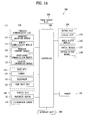
- FIG. 1A is a block diagram of a mobile terminal in accordance with the present disclosure
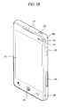
- FIGS. 1B and 1C are conceptual views of one example of the mobile terminal, viewed from different directions.
- the mobile terminal 100 is shown having components such as a wireless communication unit 110, an input unit 120, a sensing unit 140, an output unit 150, an interface unit 160, a memory 170, a controller 180, and a power supply unit 190. Implementing all of the illustrated components is not a requirement, and that greater or fewer components may alternatively be implemented. Referring now to FIG. 1A , the mobile terminal 100 is shown having wireless communication unit 110 configured with several commonly implemented components.
- the wireless communication unit 110 typically includes one or more modules which permit communications such as wireless communications between the mobile terminal 100 and a wireless communication system, communications between the mobile terminal 100 and another mobile terminal, communications between the mobile terminal 100 and an external server. Further, the wireless communication unit 110 typically includes one or more modules which connect the mobile terminal 100 to one or more networks.
- the wireless communication unit 110 includes one or more of a broadcast receiving module 111, a mobile communication module 112, a wireless Internet module 113, a short-range communication module 114, and a location information module 115.
- the input unit 120 includes a camera 121 for obtaining images or video, a microphone 122, which is one type of audio input device for inputting an audio signal, and a user input unit 123 (for example, a touch key, a push key, a mechanical key, a soft key, and the like) for allowing a user to input information.
- Data for example, audio, video, image, and the like
- controller 180 may analyze and process data (for example, audio, video, image, and the like) according to device parameters, user commands, and combinations thereof.
- the sensing unit 140 is typically implemented using one or more sensors configured to sense internal information of the mobile terminal, the surrounding environment of the mobile terminal, user information, and the like.
- the sensing unit 140 is shown having a proximity sensor 141 and an illumination sensor 142.
- the sensing unit 140 may alternatively or additionally include other types of sensors or devices, such as a touch sensor, an acceleration sensor, a magnetic sensor, a G-sensor, a gyroscope sensor, a motion sensor, an RGB sensor, an infrared (IR) sensor, a finger scan sensor, a ultrasonic sensor, an optical sensor (for example, camera 121), a microphone 122, a battery gauge, an environment sensor (for example, a barometer, a hygrometer, a thermometer, a radiation detection sensor, a thermal sensor, and a gas sensor, among others), and a chemical sensor (for example, an electronic nose, a health care sensor, a biometric sensor, and the like), to name a few.
- the mobile terminal 100 may be configured to utilize information obtained from sensing unit 140, and in particular, information obtained from one or more sensors of the sensing unit 140, and combinations thereof.
- the output unit 150 is typically configured to output various types of information, such as audio, video, tactile output, and the like.
- the output unit 150 is shown having a display unit 151, an audio output module 152, a haptic module 153, and an optical output module 154.
- the display unit 151 may have an inter-layered structure or an integrated structure with a touch sensor in order to facilitate a touch screen.
- the touch screen may provide an output interface between the mobile terminal 100 and a user, as well as function as the user input unit 123 which provides an input interface between the mobile terminal 100 and the user.
- the interface unit 160 serves as an interface with various types of external devices that can be coupled to the mobile terminal 100.
- the interface unit 160 may include any of wired or wireless ports, external power supply ports, wired or wireless data ports, memory card ports, ports for connecting a device having an identification module, audio input/output (I/O) ports, video I/O ports, earphone ports, and the like.
- the mobile terminal 100 may perform assorted control functions associated with a connected external device, in response to the external device being connected to the interface unit 160.
- the memory 170 is typically implemented to store data to support various functions or features of the mobile terminal 100.
- the memory 170 may be configured to store application programs executed in the mobile terminal 100, data or instructions for operations of the mobile terminal 100, and the like. Some of these application programs may be downloaded from an external server via wireless communication. Other application programs may be installed within the mobile terminal 100 at time of manufacturing or shipping, which is typically the case for basic functions of the mobile terminal 100 (for example, receiving a call, placing a call, receiving a message, sending a message, and the like). It is common for application programs to be stored in the memory 170, installed in the mobile terminal 100, and executed by the controller 180 to perform an operation (or function) for the mobile terminal 100.
- the controller 180 typically functions to control overall operation of the mobile terminal 100, in addition to the operations associated with the application programs.
- the controller 180 processes signals, data, information and the like input or output through the above-mentioned components and/or runs application programs saved in the memory 170, thereby processing or providing a user with appropriate information and/or functions.
- the controller 180 can provide or process information or functions appropriate for a user by processing signals, data, information and the like, which are input or output by the various components depicted in Fig. 1A , or activating application programs stored in the memory 170. As one example, the controller 180 controls some or all of the components illustrated in FIGS. 1A according to the execution of an application program that have been stored in the memory 170.
- the power supply unit 190 can be configured to receive external power or provide internal power in order to supply appropriate power required for operating elements and components included in the mobile terminal 100.
- the power supply unit 190 may include a battery, and the battery may be configured to be embedded in the terminal body, or configured to be detachable from the terminal body.
- At least one portion of the respective components mentioned in the foregoing description can cooperatively operate to embody operations, controls or controlling methods of the mobile terminal according to various embodiments of the present invention mentioned in the following description.
- the operations, controls or controlling methods of the mobile terminal can be embodied in the mobile terminal by running at least one or more application programs saved in the memory 170.
- the broadcast receiving module 111 is typically configured to receive a broadcast signal and/or broadcast associated information from an external broadcast managing entity via a broadcast channel.
- the broadcast channel may include a satellite channel, a terrestrial channel, or both.
- two or more broadcast receiving modules 111 may be utilized to facilitate simultaneously receiving of two or more broadcast channels, or to support switching among broadcast channels.
- the mobile communication module 112 can transmit and/or receive wireless signals to and from one or more network entities.
- a network entity include a base station, an external mobile terminal, a server, and the like.
- Such network entities form part of a mobile communication network, which is constructed according to technical standards or communication methods for mobile communications (for example, Global System for Mobile Communication (GSM), Code Division Multi Access (CDMA), CDMA2000 (Code Division Multi Access 2000), EV-DO (Enhanced Voice-Data Optimized or Enhanced Voice-Data Only), Wideband CDMA (WCDMA), High Speed Downlink Packet access (HSDPA), HSUPA (High Speed Uplink Packet Access), Long Term Evolution (LTE), LTE-A (Long Term Evolution-Advanced), and the like).
- GSM Global System for Mobile Communication
- CDMA Code Division Multi Access
- CDMA2000 Code Division Multi Access 2000
- EV-DO Enhanced Voice-Data Optimized or Enhanced Voice-Data Only
- WCDMA Wideband CDMA
- HSDPA High Speed Downlink
- wireless signals transmitted and/or received via the mobile communication module 112 include audio call signals, video (telephony) call signals, or various formats of data to support communication of text and multimedia messages.
- the wireless Internet module 113 is configured to facilitate wireless Internet access. This module may be internally or externally coupled to the mobile terminal 100. The wireless Internet module 113 may transmit and/or receive wireless signals via communication networks according to wireless Internet technologies.
- wireless Internet access examples include Wireless LAN (WLAN), Wireless Fidelity (Wi-Fi), Wi-Fi Direct, Digital Living Network Alliance (DLNA), Wireless Broadband (WiBro), Worldwide Interoperability for Microwave Access (WiMAX), High Speed Downlink Packet Access (HSDPA), HSUPA (High Speed Uplink Packet Access), Long Term Evolution (LTE), LTE-A (Long Term Evolution-Advanced), and the like.
- the wireless Internet module 113 may transmit/receive data according to one or more of such wireless Internet technologies, and other Internet technologies as well.
- the wireless Internet module 113 when the wireless Internet access is implemented according to, for example, WiBro, HSDPA,HSUPA, GSM, CDMA, WCDMA, LTE, LTE-A and the like, as part of a mobile communication network, the wireless Internet module 113 performs such wireless Internet access. As such, the Internet module 113 may cooperate with, or function as, the mobile communication module 112.
- the short-range communication module 114 is configured to facilitate short-range communications. Suitable technologies for implementing such short-range communications include BLUETOOTHTM, Radio Frequency IDentification (RFID), Infrared Data Association (IrDA), Ultra-WideBand (UWB), ZigBee, Near Field Communication (NFC), Wireless-Fidelity (Wi-Fi), Wi-Fi Direct, Wireless USB (Wireless Universal Serial Bus), and the like.
- the short-range communication module 114 in general supports wireless communications between the mobile terminal 100 and a wireless communication system, communications between the mobile terminal 100 and another mobile terminal 100, or communications between the mobile terminal and a network where another mobile terminal 100 (or an external server) is located, via wireless area networks.
- One example of the wireless area networks is a wireless personal area networks.
- another mobile terminal (which may be configured similarly to mobile terminal 100) may be a wearable device, for example, a smart watch, a smart glass or a head mounted display (HMD), which can exchange data with the mobile terminal 100 (or otherwise cooperate with the mobile terminal 100).
- the short-range communication module 114 may sense or recognize the wearable device, and permit communication between the wearable device and the mobile terminal 100.
- the controller 180 when the sensed wearable device is a device which is authenticated to communicate with the mobile terminal 100, the controller 180, for example, may cause transmission of data processed in the mobile terminal 100 to the wearable device via the short-range communication module 114.
- a user of the wearable device may use the data processed in the mobile terminal 100 on the wearable device. For example, when a call is received in the mobile terminal 100, the user can answer the call using the wearable device. Also, when a message is received in the mobile terminal 100, the user can check the received message using the wearable device.
- the location information module 115 is generally configured to detect, calculate, derive or otherwise identify a position of the mobile terminal.
- the location information module 115 includes a Global Position System (GPS) module, a Wi-Fi module, or both. If desired, the location information module 115 may alternatively or additionally function with any of the other modules of the wireless communication unit 110 to obtain data related to the position of the mobile terminal.
- GPS Global Position System
- a position of the mobile terminal may be acquired using a signal sent from a GPS satellite.
- Wi-Fi module a position of the mobile terminal can be acquired based on information related to a wireless access point (AP) which transmits or receives a wireless signal to or from the Wi-Fi module.
- AP wireless access point
- the input unit 120 may be configured to permit various types of input to the mobile terminal 120. Examples of such input include audio, image, video, data, and user input.
- Image and video input is often obtained using one or more cameras 121. Such cameras 121 may process image frames of still pictures or video obtained by image sensors in a video or image capture mode. The processed image frames can be displayed on the display unit 151 or stored in memory 170.
- the cameras 121 may be arranged in a matrix configuration to permit a plurality of images having various angles or focal points to be input to the mobile terminal 100. As another example, the cameras 121 may be located in a stereoscopic arrangement to acquire left and right images for implementing a stereoscopic image.
- the microphone 122 is generally implemented to permit audio input to the mobile terminal 100.
- the audio input can be processed in various manners according to a function being executed in the mobile terminal 100.
- the microphone 122 may include assorted noise removing algorithms to remove unwanted noise generated in the course of receiving the external audio.
- the user input unit 123 is a component that permits input by a user. Such user input may enable the controller 180 to control operation of the mobile terminal 100.
- the user input unit 123 may include one or more of a mechanical input element (for example, a key, a button located on a front and/or rear surface or a side surface of the mobile terminal 100, a dome switch, a jog wheel, a jog switch, and the like), or a touch-sensitive input, among others.
- the touch-sensitive input may be a virtual key or a soft key, which is displayed on a touch screen through software processing, or a touch key which is located on the mobile terminal at a location that is other than the touch screen.
- the virtual key or the visual key may be displayed on the touch screen in various shapes, for example, graphic, text, icon, video, or a combination thereof.
- the sensing unit 140 is generally configured to sense one or more of internal information of the mobile terminal, surrounding environment information of the mobile terminal, user information, or the like.
- the controller 180 generally cooperates with the sending unit 140 to control operation of the mobile terminal 100 or execute data processing, a function or an operation associated with an application program installed in the mobile terminal based on the sensing provided by the sensing unit 140.
- the sensing unit 140 may be implemented using any of a variety of sensors, some of which will now be described in more detail.
- the proximity sensor 141 may include a sensor to sense presence or absence of an object approaching a surface, or an object located near a surface, by using an electromagnetic field, infrared rays, or the like without a mechanical contact.
- the proximity sensor 141 may be arranged at an inner region of the mobile terminal covered by the touch screen, or near the touch screen.
- the proximity sensor 141 may include any of a transmissive type photoelectric sensor, a direct reflective type photoelectric sensor, a mirror reflective type photoelectric sensor, a high-frequency oscillation proximity sensor, a capacitance type proximity sensor, a magnetic type proximity sensor, an infrared rays proximity sensor, and the like.
- the proximity sensor 141 can sense proximity of a pointer relative to the touch screen by changes of an electromagnetic field, which is responsive to an approach of an object with conductivity.
- the touch screen may also be categorized as a proximity sensor.
- proximity touch will often be referred to herein to denote the scenario in which a pointer is positioned to be proximate to the touch screen without contacting the touch screen.
- contact touch will often be referred to herein to denote the scenario in which a pointer makes physical contact with the touch screen.
- the proximity sensor 141 may sense proximity touch, and proximity touch patterns (for example, distance, direction, speed, time, position, moving status, and the like).
- controller 180 processes data corresponding to proximity touches and proximity touch patterns sensed by the proximity sensor 141, and cause output of visual information on the touch screen.
- the controller 180 can control the mobile terminal 100 to execute different operations or process different data according to whether a touch with respect to a point on the touch screen is either a proximity touch or a contact touch.
- a touch sensor can sense a touch applied to the touch screen, such as display unit 151, using any of a variety of touch methods. Examples of such touch methods include a resistive type, a capacitive type, an infrared type, and a magnetic field type, among others. As one example, the touch sensor may be configured to convert changes of pressure applied to a specific part of the display unit 151, or convert capacitance occurring at a specific part of the display unit 151, into electric input signals. The touch sensor may also be configured to sense not only a touched position and a touched area, but also touch pressure and/or touch capacitance.
- a touch object is generally used to apply a touch input to the touch sensor. Examples of typical touch objects include a finger, a touch pen, a stylus pen, a pointer, or the like.
- a touch controller When a touch input is sensed by a touch sensor, corresponding signals may be transmitted to a touch controller.
- the touch controller may process the received signals, and then transmit corresponding data to the controller 180. Accordingly, the controller 180 can sense which region of the display unit 151 has been touched.
- the touch controller may be a component separate from the controller 180, the controller 180, and combinations thereof.
- the controller 180 can execute the same or different controls according to a type of touch object that touches the touch screen or a touch key provided in addition to the touch screen. Whether to execute the same or different control according to the object which provides a touch input may be decided based on a current operating state of the mobile terminal 100 or a currently executed application program, for example.
- the touch sensor and the proximity sensor may be implemented individually, or in combination, to sense various types of touches.
- Such touches includes a short (or tap) touch, a long touch, a multi-touch, a drag touch, a flick touch, a pinch-in touch, a pinch-out touch, a swipe touch, a hovering touch, and the like.
- an ultrasonic sensor may be implemented to recognize position information relating to a touch object using ultrasonic waves.
- the controller 180 may calculate a position of a wave generation source based on information sensed by an illumination sensor and a plurality of ultrasonic sensors. Since light is much faster than ultrasonic waves, the time for which the light reaches the optical sensor is much shorter than the time for which the ultrasonic wave reaches the ultrasonic sensor. The position of the wave generation source may be calculated using this fact. For instance, the position of the wave generation source may be calculated using the time difference from the time that the ultrasonic wave reaches the sensor based on the light as a reference signal.
- the camera 121 typically includes at least one a camera sensor (CCD, CMOS etc.), a photo sensor (or image sensors), and a laser sensor.
- a laser sensor may allow detection of a touch of a physical object with respect to a 3D stereoscopic image.
- the photo sensor may be laminated on, or overlapped with, the display device.
- the photo sensor may be configured to scan movement of the physical object in proximity to the touch screen.
- the photo sensor may include photo diodes and transistors at rows and columns to scan content received at the photo sensor using an electrical signal which changes according to the quantity of applied light. Namely, the photo sensor may calculate the coordinates of the physical object according to variation of light to thus obtain position information of the physical object.
- the display unit 151 is generally configured to output information processed in the mobile terminal 100.
- the display unit 151 may display execution screen information of an application program executing at the mobile terminal 100 or user interface (UI) and graphic user interface (GUI) information in response to the execution screen information.
- UI user interface
- GUI graphic user interface
- the display unit 151 may be implemented as a stereoscopic display unit for displaying stereoscopic images.
- a typical stereoscopic display unit may employ a stereoscopic display scheme such as a stereoscopic scheme (a glass scheme), an auto-stereoscopic scheme (glassless scheme), a projection scheme (holographic scheme), or the like.
- the audio output module 152 is generally configured to output audio data. Such audio data may be obtained from any of a number of different sources, such that the audio data may be received from the wireless communication unit 110 or may have been stored in the memory 170. The audio data may be output during modes such as a signal reception mode, a call mode, a record mode, a voice recognition mode, a broadcast reception mode, and the like. The audio output module 152 can provide audible output related to a particular function (e.g., a call signal reception sound, a message reception sound, etc.) performed by the mobile terminal 100. The audio output module 152 may also be implemented as a receiver, a speaker, a buzzer, or the like.
- a haptic module 153 can be configured to generate various tactile effects that a user feels, perceive, or otherwise experience.
- a typical example of a tactile effect generated by the haptic module 153 is vibration.
- the strength, pattern and the like of the vibration generated by the haptic module 153 can be controlled by user selection or setting by the controller. For example, the haptic module 153 may output different vibrations in a combining manner or a sequential manner.
- the haptic module 153 can generate various other tactile effects, including an effect by stimulation such as a pin arrangement vertically moving to contact skin, a spray force or suction force of air through a jet orifice or a suction opening, a touch to the skin, a contact of an electrode, electrostatic force, an effect by reproducing the sense of cold and warmth using an element that can absorb or generate heat, and the like.
- an effect by stimulation such as a pin arrangement vertically moving to contact skin, a spray force or suction force of air through a jet orifice or a suction opening, a touch to the skin, a contact of an electrode, electrostatic force, an effect by reproducing the sense of cold and warmth using an element that can absorb or generate heat, and the like.
- the haptic module 153 can also be implemented to allow the user to feel a tactile effect through a muscle sensation such as the user's fingers or arm, as well as transferring the tactile effect through direct contact. Two or more haptic modules 153 may be provided according to the particular configuration of the mobile terminal 100.
- An optical output module 154 can output a signal for indicating an event generation using light of a light source. Examples of events generated in the mobile terminal 100 may include message reception, call signal reception, a missed call, an alarm, a schedule notice, an email reception, information reception through an application, and the like.
- a signal output by the optical output module 154 may be implemented so the mobile terminal emits monochromatic light or light with a plurality of colors.
- the signal output may be terminated as the mobile terminal senses that a user has checked the generated event, for example.
- the interface unit 160 serves as an interface for external devices to be connected with the mobile terminal 100.
- the interface unit 160 can receive data transmitted from an external device, receive power to transfer to elements and components within the mobile terminal 100, or transmit internal data of the mobile terminal 100 to such external device.
- the interface unit 160 may include wired or wireless headset ports, external power supply ports, wired or wireless data ports, memory card ports, ports for connecting a device having an identification module, audio input/output (I/O) ports, video I/O ports, earphone ports, or the like.
- the identification module may be a chip that stores various information for authenticating authority of using the mobile terminal 100 and may include a user identity module (UIM), a subscriber identity module (SIM), a universal subscriber identity module (USIM), and the like.
- the device having the identification module (also referred to herein as an "identifying device") may take the form of a smart card. Accordingly, the identifying device can be connected with the terminal 100 via the interface unit 160.
- the interface unit 160 can serve as a passage to allow power from the cradle to be supplied to the mobile terminal 100 or may serve as a passage to allow various command signals input by the user from the cradle to be transferred to the mobile terminal there through.
- Various command signals or power input from the cradle may operate as signals for recognizing that the mobile terminal is properly mounted on the cradle.
- the memory 170 can store programs to support operations of the controller 180 and store input/output data (for example, phonebook, messages, still images, videos, etc.).
- the memory 170 may store data related to various patterns of vibrations and audio which are output in response to touch inputs on the touch screen.
- the memory 170 may include one or more types of storage mediums including a Flash memory, a hard disk, a solid state disk, a silicon disk, a multimedia card micro type, a card-type memory (e.g., SD or DX memory, etc.), a Random Access Memory (RAM), a Static Random Access Memory (SRAM), a Read-Only Memory (ROM), an Electrically Erasable Programmable Read-Only Memory (EEPROM), a Programmable Read-Only memory (PROM), a magnetic memory, a magnetic disk, an optical disk, and the like.
- the mobile terminal 100 may also be operated in relation to a network storage device that performs the storage function of the memory 170 over a network, such as the Internet.
- the controller 180 can typically control the general operations of the mobile terminal 100. For example, the controller 180 can set or release a lock state for restricting a user from inputting a control command with respect to applications when a status of the mobile terminal meets a preset condition.
- the controller 180 can also perform the controlling and processing associated with voice calls, data communications, video calls, and the like, or perform pattern recognition processing to recognize a handwriting input or a picture drawing input performed on the touch screen as characters or images, respectively.
- the controller 180 can control one or a combination of those components in order to implement various exemplary embodiments disclosed herein.
- the power supply unit 190 receives external power or provide internal power and supply the appropriate power required for operating respective elements and components included in the mobile terminal 100.
- the power supply unit 190 may include a battery, which is typically rechargeable or be detachably coupled to the terminal body for charging.
- the power supply unit 190 may include a connection port.
- the connection port may be configured as one example of the interface unit 160 to which an external charger for supplying power to recharge the battery is electrically connected.
- the power supply unit 190 may be configured to recharge the battery in a wireless manner without use of the connection port.
- the power supply unit 190 can receive power, transferred from an external wireless power transmitter, using at least one of an inductive coupling method which is based on magnetic induction or a magnetic resonance coupling method which is based on electromagnetic resonance.
- an inductive coupling method which is based on magnetic induction
- a magnetic resonance coupling method which is based on electromagnetic resonance.
- Various embodiments described herein may be implemented in a computer-readable medium, a machine-readable medium, or similar medium using, for example, software, hardware, or any combination thereof.
- the mobile terminal 100 is described with reference to a bar-type terminal body.
- the mobile terminal 100 may alternatively be implemented in any of a variety of different configurations. Examples of such configurations include watch-type, clip-type, glasses-type, or as a folder-type, flip-type, slide-type, swing-type, and swivel-type in which two and more bodies are combined with each other in a relatively movable manner, and combinations thereof. Discussion herein will often relate to a particular type of mobile terminal (for example, bar-type, watch-type, glasses-type, and the like). However, such teachings with regard to a particular type of mobile terminal will generally apply to other types of mobile terminals as well.
- the mobile terminal 100 will generally include a case (for example, frame, housing, cover, and the like) forming the appearance of the terminal.
- the case is formed using a front case 101 and a rear case 102.
- Various electronic components are incorporated into a space formed between the front case 101 and the rear case 102.
- At least one middle case may be additionally positioned between the front case 101 and the rear case 102.
- the display unit 151 is shown located on the front side of the terminal body to output information. As illustrated, a window 151a of the display unit 151 may be mounted to the front case 101 to form the front surface of the terminal body together with the front case 101.
- electronic components may also be mounted to the rear case 102. Examples of such electronic components include a detachable battery 191, an identification module, a memory card, and the like.
- Rear cover 103 is shown covering the electronic components, and this cover may be detachably coupled to the rear case 102. Therefore, when the rear cover 103 is detached from the rear case 102, the electronic components mounted to the rear case 102 are externally exposed.
- the rear cover 103 when the rear cover 103 is coupled to the rear case 102, a side surface of the rear case 102 is partially exposed. In some cases, upon the coupling, the rear case 102 may also be completely shielded by the rear cover 103. In some embodiments, the rear cover 103 may include an opening for externally exposing a camera 121b or an audio output module 152b.
- the cases 101, 102, 103 may be formed by injection-molding synthetic resin or may be formed of a metal, for example, stainless steel (STS), aluminum (Al), titanium (Ti), or the like.
- STS stainless steel
- Al aluminum
- Ti titanium
- the mobile terminal 100 may be configured such that one case forms the inner space.
- a mobile terminal 100 having a uni-body is formed so synthetic resin or metal extends from a side surface to a rear surface.
- the mobile terminal 100 may include a waterproofing unit for preventing introduction of water into the terminal body.
- the waterproofing unit may include a waterproofing member which is located between the window 151a and the front case 101, between the front case 101 and the rear case 102, or between the rear case 102 and the rear cover 103, to hermetically seal an inner space when those cases are coupled.
- the mobile terminal 100 may be provided with the display unit 151, the first audio output unit 152a, the second audio output unit 152b, the proximity sensor 141, the illumination sensor 142, the light output unit 154, the first camera 121a, the second camera 121b, the first manipulating unit 123a, the second manipulating unit 123b, the microphone 122, the interface unit 160, and the like.
- FIGS. 1B and 1C depict certain components as arranged on the mobile terminal. However, alternative arrangements are possible and within the teachings of the instant disclosure. Some components may be omitted or rearranged.
- the first manipulation unit 123a may be located on another surface of the terminal body
- the second audio output module 152b may be located on the side surface of the terminal body.
- the display unit 151 outputs information processed in the mobile terminal 100.
- the display unit 151 may be implemented using one or more suitable display devices. Examples of such suitable display devices include a liquid crystal display (LCD), a thin film transistor-liquid crystal display (TFT-LCD), an organic light emitting diode (OLED), a flexible display, a 3-dimensional (3D) display, an e-ink display, and combinations thereof.
- the display unit 151 may be implemented using two display devices, which can implement the same or different display technology. For instance, a plurality of the display units 151 may be arranged on one side, either spaced apart from each other, or these devices may be integrated, or these devices may be arranged on different surfaces.
- the display unit 151 may also include a touch sensor which senses a touch input received at the display unit.
- the touch sensor may be configured to sense this touch and the controller 180, for example, may generate a control command or other signal corresponding to the touch.
- the content which is input in the touching manner may be a text or numerical value, or a menu item which can be indicated or designated in various modes.
- the touch sensor may be configured in a form of a film having a touch pattern, disposed between the window 151a and a display on a rear surface of the window 151a, or a metal wire which is patterned directly on the rear surface of the window 151a.
- the touch sensor may be integrally formed with the display.
- the touch sensor may be disposed on a substrate of the display or within the display.
- the display unit 151 may also form a touch screen together with the touch sensor.
- the touch screen may serve as the user input unit 123 (see FIG. 1A ). Therefore, the touch screen may replace at least some of the functions of the first manipulation unit 123a.
- the first audio output module 152a may be implemented in the form of a speaker to output voice audio, alarm sounds, multimedia audio reproduction, and the like.
- the window 151a of the display unit 151 will typically include an aperture to permit audio generated by the first audio output module 152a to pass.
- One alternative is to allow audio to be released along an assembly gap between the structural bodies (for example, a gap between the window 151a and the front case 101). In this instance, a hole independently formed to output audio sounds may not be seen or is otherwise hidden in terms of appearance, thereby further simplifying the appearance and manufacturing of the mobile terminal 100.
- the optical output module 154 can be configured to output light for indicating an event generation. Examples of such events include a message reception, a call signal reception, a missed call, an alarm, a schedule notice, an email reception, information reception through an application, and the like.
- the controller can control the optical output unit 154 to stop the light output.
- the first camera 121a can process image frames such as still or moving images obtained by the image sensor in a capture mode or a video call mode.
- the processed image frames can then be displayed on the display unit 151 or stored in the memory 170.
- the first and second manipulation units 123a and 123b are examples of the user input unit 123, which may be manipulated by a user to provide input to the mobile terminal 100.
- the first and second manipulation units 123a and 123b may also be commonly referred to as a manipulating portion, and may employ any tactile method that allows the user to perform manipulation such as touch, push, scroll, or the like.
- the first and second manipulation units 123a and 123b may also employ any non-tactile method that allows the user to perform manipulation such as proximity touch, hovering, or the like.
- FIG. 1B illustrates the first manipulation unit 123a as a touch key, but possible alternatives include a mechanical key, a push key, a touch key, and combinations thereof.
- Input received at the first and second manipulation units 123a and 123b may be used in various ways.
- the first manipulation unit 123a may be used by the user to provide an input to a menu, home key, cancel, search, or the like
- the second manipulation unit 123b may be used by the user to provide an input to control a volume level being output from the first or second audio output modules 152a or 152b, to switch to a touch recognition mode of the display unit 151, or the like.
- a rear input unit may be located on the rear surface of the terminal body.
- the rear input unit can be manipulated by a user to provide input to the mobile terminal 100.
- the input may be used in a variety of different ways.
- the rear input unit may be used by the user to provide an input for power on/off, start, end, scroll, control volume level being output from the first or second audio output modules 152a or 152b, switch to a touch recognition mode of the display unit 151, and the like.
- the rear input unit may be configured to permit touch input, a push input, or combinations thereof.
- the rear input unit may be located to overlap the display unit 151 of the front side in a thickness direction of the terminal body.
- the rear input unit may be located on an upper end portion of the rear side of the terminal body such that a user can easily manipulate it using a forefinger when the user grabs the terminal body with one hand.
- the rear input unit can be positioned at most any location of the rear side of the terminal body.
- Embodiments that include the rear input unit may implement some or all of the functionality of the first manipulation unit 123a in the rear input unit. As such, in situations where the first manipulation unit 123a is omitted from the front side, the display unit 151 can have a larger screen.
- the mobile terminal 100 may include a finger scan sensor which scans a user's fingerprint. The controller 180 can then use fingerprint information sensed by the finger scan sensor as part of an authentication procedure. The finger scan sensor may also be installed in the display unit 151 or implemented in the user input unit 123.
- the microphone 122 is shown located at an end of the mobile terminal 100, but other locations are possible. If desired, multiple microphones may be implemented, with such an arrangement permitting the receiving of stereo sounds.
- the interface unit 160 may serve as a path allowing the mobile terminal 100 to interface with external devices.
- the interface unit 160 may include one or more of a connection terminal for connecting to another device (for example, an earphone, an external speaker, or the like), a port for near field communication (for example, an Infrared Data Association (IrDA) port, a Bluetooth port, a wireless LAN port, and the like), or a power supply terminal for supplying power to the mobile terminal 100.
- the interface unit 160 may be implemented in the form of a socket for accommodating an external card, such as Subscriber Identification Module (SIM), User Identity Module (UIM), or a memory card for information storage.
- SIM Subscriber Identification Module
- UIM User Identity Module
- the second camera 121b is shown located at the rear side of the terminal body and includes an image capturing direction that is substantially opposite to the image capturing direction of the first camera unit 121a. If desired, second camera 121a may alternatively be located at other locations, or made to be moveable, in order to have a different image capturing direction from that which is shown.
- the second camera 121b can include a plurality of lenses arranged along at least one line.
- the plurality of lenses may also be arranged in a matrix configuration.
- the cameras may be referred to as an "array camera.”
- the second camera 121b is implemented as an array camera, images may be captured in various manners using the plurality of lenses and images with better qualities.
- a flash 124 is shown adjacent to the second camera 121b.
- the flash 124 may illuminate the subject.
- the second audio output module 152b can be located on the terminal body.
- the second audio output module 152b may implement stereophonic sound functions in conjunction with the first audio output module 152a, and may be also used for implementing a speaker phone mode for call communication.
- At least one antenna for wireless communication may be located on the terminal body.
- the antenna may be installed in the terminal body or formed by the case.
- an antenna which configures a part of the broadcast receiving module 111 may be retractable into the terminal body.
- an antenna may be formed using a film attached to an inner surface of the rear cover 103, or a case that includes a conductive material.
- a power supply unit 190 for supplying power to the mobile terminal 100 may include a battery 191, which is mounted in the terminal body or detachably coupled to an outside of the terminal body.
- the battery 191 may receive power via a power source cable connected to the interface unit 160.
- the battery 191 can be recharged in a wireless manner using a wireless charger. Wireless charging may be implemented by magnetic induction or electromagnetic resonance.
- the rear cover 103 is shown coupled to the rear case 102 for shielding the battery 191, to prevent separation of the battery 191, and to protect the battery 191 from an external impact or from foreign material.
- the rear case 103 may be detachably coupled to the rear case 102.
- An accessory for protecting an appearance or assisting or extending the functions of the mobile terminal 100 can also be provided on the mobile terminal 100.
- a cover or pouch for covering or accommodating at least one surface of the mobile terminal 100 may be provided.
- the cover or pouch may cooperate with the display unit 151 to extend the function of the mobile terminal 100.
- a touch pen for assisting or extending a touch input to a touch screen is another example of the accessory.
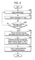
- FIG. 2 is a flowchart of a controlling method for performing a considerable amount of scroll using a prescribed touch gesture according to one embodiment of the present invention.
- FIG. 3 is a diagram of state configuration for a control method of performing a considerable amount of scroll using a prescribed touch gesture according to one embodiment of the present invention. The following description is made with reference to FIG. 2 and FIG. 3 together.
- a touch gesture is applied as if drawing a slingshot.
- a scroll action to be performed on a screen is controlled using a touch gesture applied by applying a touch to a first point on the touchscreen 151, dragging the touch to a second point, and then releasing the touch.
- the controller 180 outputs a content screen ( FIG. 3 (a) ).
- a content screen FIG. 3 (a)
- the content screen may include one of a web browser running screen, a content list screen, a music play list screen and the like.
- a step S202 the controller 180 receives a touch input 10a to a first point 301 on the touchscreen 151 ( FIG. 3 (a) ).
- a step S203 the controller 180 determines whether the touch input 10a is held over a prescribed time without being released. As a result of the determination, if the touch input 10a fails to be held over the prescribed time (No in S203), the routine goes back to the step S201. As a result of the determination, if the touch input 10a is held over the prescribed time (Yes in S203), the routine goes to a step S204.
- the reason for determining whether the touch input is held is to distinguish the above-mentioned touch input from other touch gestures. If it is preset to perform a different action using a touch-drag input, the former touch-drag input should be distinguished from a touch-drag input of one embodiment of the present invention. Therefore, according to one embodiment of the present invention, the controller 180 determines whether a touch is held over a prescribed time in order to be distinguished from an action of touch-drag used in general.
- the gesture of dragging the touch input 10a to the second point 302 from the first point 301 and the gesture of holding the touch can be applied to one embodiment of the present invention irrespective of the order for inputting the two gestures.
- the case of holding the touch input 10a over the prescribed time and then dragging the touch input 10a to the second point or the case of dragging the touch input to the second point and then holding the touch input, or the case of dragging the touch input to an in-between point between the first point and the second point, holding the touch input over a prescribed time, and then dragging the touch input to the second point is applicable to one embodiment of the present invention.
- the touch input 10a is applied in random order of dragging and holding, by which the order of applying the touch input 10a is non-limited.
- a step S204 referring to FIG. 3 (b) , the controller 180 can detect that the touch input 10a is released from the second point 302 by the drag movement.
- the controller 180 determines a prescribed scroll distance based on a distance between the first point and the second point or a time for holding the touch input 10a.
- a control method of determining a scroll distance shall be described in detail later with reference to the accompanying drawings later.
- a direction of the scroll movement may include a direction from a second location toward a first location.
- the controller 180 since the direction from the second position toward the first location is a top direction, if the touch input is released, the controller 180 can control the content screen to be scrolled to move in the top direction.
- the controller 180 has determined the scroll distance. A method of determining the scroll distance is described in detail with reference to FIG. 4 and FIG. 5 as follows.
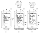
- FIG. 4 is a diagram illustrating a first example of determining a scroll distance according to one embodiment of the present invention.
- the controller 180 determines a scroll distance based on a touch drag distance (e.g., a distance between a first location and a second location).
- a touch drag distance means a distance between a first point having a touch input applied thereto and a second point that is a currently touched point.
- the mobile terminal 100 receives a user's touch input 10b through a first point 401 of the touchscreen 151. And, assume that the received touch input 10b is held over a prescribed time.
- the controller 180 can determine a scroll distance based on a touched & dragged distance.
- the controller 180 can scroll to move the screen by a first scroll distance.
- the first scroll distance is determined based on a distance d1 between the first point 401 and the second point 402.
- the controller 180 can control the scroll distance to be determined in proportion to the distance d1.
- the controller 180 can determine the scroll distance by multiplying the distance d1 by a prescribed numerical value.
- the controller 180 can scroll to move the screen by a second scroll distance.
- the second scroll distance can be determined based on a distance d2 between the first point 401 and the third point 403.
- a distance indicator 400 for guiding a scroll distance can be further output. Since a scroll controlling method according to one embodiment of the present invention is the control method for facilitating a considerable amount of scroll, an amount of movement by scroll may be considerably large. Hence, according to one embodiment of the present invention, in order to indicate a prescribed amount of scroll, the controller 180 outputs the distance indicator 400.
- the distance indicator 400 can be represented as a percentage of a scroll distance over a total scrollable amount (i.e., a total length of a content screen). Referring to FIG. 4 (b) , the distance indicator 400 indicates 52%, which may mean that the first scroll distance determined by the distance d1 amounts to 52% of the total scrollable amount. Likewise, the distance indicator 400 shown in FIG. 4 (c) means that the second scroll distance amounts to 88% of the total scrollable amount.
- FIG. 5 is a diagram illustrating a second example of determining a scroll distance according to one embodiment of the present invention.
- the controller 180 determines a scroll distance based on a touch held time.
- the mobile terminal 100 receives a user's touch input 10c through a first point 501 of the touchscreen 151.
- the controller 180 can determine a scroll distance based on a touch held time. Referring to FIG. 5 (b) , after the touch input 10c has been dragged to a second point 502, if the touch input 10c is released after the elapse of a first time, the controller 180 can scroll to move the screen by a first scroll distance. In this instance, the first scroll distance is determined based on the first time.
- the controller 180 can control the scroll distance to be determined in proportion to the first time.
- the controller 180 can determine the scroll distance by multiplying the first time by a prescribed numerical value. If the touch input 10c is dragged to a second point 502 and then released after an elapse of a second time, as shown in FIG. 5 (c) , the controller 180 can scroll to move the screen by a second scroll distance. In this instance, the second scroll distance can be determined based on the second time.
- a distance indicator 400 for guiding a scroll distance can be further output as well. Since the distance indicator 400 is as good as described with reference to FIG. 4 , its details are omitted form the following description. According to one embodiment of the present invention, since an amount of movement by scroll is considerably large, it is difficult to estimate an amount of a scroll applied by a user. Therefore, according to one embodiment of the present invention, the controller 180 displays a preview image for an item of a point moved by a scroll. Such an embodiment is described in detail with reference to FIG. 6A and FIG. 6B as follows.
- FIG. 6A and FIG. 6B are diagrams illustrating state configurations for a control method of outputting a preview image of a destination item on a scroll movement according to one embodiment of the present invention.
- an exterior of the mobile terminal 100 is omitted but a state configuration of the touchscreen 151 is illustrated only.
- the mobile terminal 100 outputs a music content play list 601 through the touchscreen 151. If the scroll controlling method is applied to the music content play list 601, the controller 180 can scroll to move the music content play list 601. If the number of content items included in the music content play list 601 is big, a user can have difficulty in estimating a scrolled location on the list. Therefore, according to one embodiment of the present invention, the controller 180 outputs a preview image of a destination item reached by the scroll movement while a touch is held.
- a user applies a touch input 10d to a first point on the music content play list 601 output through the touchscreen 151 and then moves a touch point to a second point. While the touch input 10d is held, the controller 180 determines a destination item (cf. 603 shown in FIG. 6A(c) ) for a destination of the corresponding movement in response to a release of the touch input and can then output a preview image 602 of the corresponding destination item 603 to a prescribed region (cf. FIG. 6A(a) ).
- the controller 180 can scroll to move the music content play list 601. Subsequently, referring to FIG. 6A(c) , the controller 180 can move the screen to the prescribed destination item 603 by scroll.
- the preview image 602 output in FIG. 6A(a) may include an album image of the prescribed destination item 603.
- a photo included in the corresponding post may be displayed as the preview image 602 (cf. the part related to FIG. 9 ).
- the controller 180 determines the changed destination item again and can then change the preview image 602.
- FIG. 6B Such an embodiment is described in detail with reference to FIG. 6B as follows.
- the distance d1 may mean a distance between a first point 605 having a touch input 10d applied thereto and a second point 606-1 currently touched by touch & drag.
- the controller 180 can output a first preview image 602-1 of a first destination item by a scroll movement.
- the controller 180 can output a third preview image 602-3 of a third destination item by switching a previously output preview image to the third preview image 602-3.
- an index for passing through is set at a prescribed item.
- the controller 180 pauses the scroll movement at the index-set prescribed passing-through item.
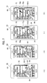
- FIG. 7 is a diagram illustrating a control method of designating an index item of a scroll movement according to one embodiment of the present invention.
- a user can desire to check a plurality of items on a scroll movement.
- the controller 180 sets an index for designating a passing-through item before arriving at a final destination item of a scroll movement. For instance, if an index is set at a first item and a second item is set as a destination, a scroll movement can be performed by being paused at the first item and then moving to the second item.
- a music content play item 601 is currently output through the touchscreen 151. If a user's scroll control command 10e is input, a first preview image 602-1 is currently output. Thereafter, if an index setting command (e.g., an input of applying a touch 10f to the first preview image 602-1) is received, the controller 180 can perform an index setting on a first destination item corresponding to the first preview image 602-1. In particular, the controller 180 can save an index information on the first destination item. In this instance, the corresponding index information may include an identification information of the first destination item.
- an index setting command e.g., an input of applying a touch 10f to the first preview image 602-1
- the controller 180 when the index information on the first destination item is saved, the controller 180 can output an indication bar 602 configured to indicate a relative location of the first destination item in a whole scroll region. If an index is set at the first destination item, referring to FIG. 7 (b) , the controller 180 can display a first index 701a, which indicates the relative location of the first destination item, on the indication bar 602.
- the controller 180 can output a second preview image 602-2 as shown in FIG. 7 (c) for a second destination item corresponding to the changed distance.
- the controller 180 can display a second index 701b, which indicates a relative location of the second destination item, on the indication bar 602 likewise.
- FIG. 8A is a diagram illustrating a control method of pausing a scroll at an index set item on a scroll movement according to one embodiment of the present invention.
- FIG. 8A(a) while the indexes are set at the first destination item and the second destination item like FIG. 7 , respectively, a touch of a touch input 10e is released.
- the controller 180 can perform a scroll movement.
- the controller 180 In performing the scroll movement, referring to FIG. 8A(c) , the controller 180 pauses the scroll at a first destination item 801. Thereafter, if a resume command is received, the controller 180 can resume the scroll to arrive at the first destination item 801. When the scroll movement to the first destination item 801 is performed, the controller 180 can additionally display an indication 802 of a scroll movement extent on an indication bar 602.
- the controller 180 can utilize the saved index information when reading a list again in the future. In particular, after an application has ended, if the application is launched again, the controller 180 maintains the index information. Such an embodiment is described in detail with reference to FIG. 8B as follows.
- FIG. 8B is a diagram illustrating a control method of facilitating a scroll movement to a prescribed item using an index information despite re-launching a prescribed application after ending the prescribed application according to one embodiment of the present invention.
- the first index 701a and the second index 701b set in FIG. 8A are currently displayed on the indication bar 602. After the indexes have been set in FIG. 8A , a corresponding application is launched again. If an input of selecting one of the first index 701a and the second index 702b is received, the controller 180 can scroll to move to an item indicated by the selected index ( FIG. 8B(c) ). In particular, if an input 10j of touching the first index 701a is received ( FIG. 8B(b) ), the controller 180 can scroll to move to a first destination item 801 corresponding to the index information set at the first index 701a.
- the controller 180 can additionally display an indication 802, which indicates a scroll-moved extent, on the indication bar 602.
- a full content screen before the additional content loading can differ from that after the additional content loading in size.
- the controller 180 performs a scroll movement action with reference to a full content screen after the loading. Examples are described in detail with reference to FIG. 9 and FIG. 10 as follows.
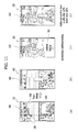
- FIG. 9 is a diagram of state configuration for a control method of displaying a preview image on an SNS application according to one embodiment of the present invention.
- an album image of a destination item is displayed as a preview image.
- a photo contained in the corresponding post can be output as a preview image.
- a list 900 of post items is currently output on an SNS application. If a touch input 10f for scrolling the post list 900 is received, the controller 180 can output a first preview image 602-1 for a destination item (cf. 901 in FIG. 9 (c) ). And, a distance indicator displayed in response to the touch input 10f indicates 65%.
- FIG. 9 (b) since the touch input 10f is additionally dragged, if a touch drag length increases, a value of the distance indicator can increase to indicate 100%. And, an image for a corresponding destination item can be changed to a second preview image 602-2 (cf. the former description with reference to FIGs. 6B(a) to 6B(c) ). Referring to FIG. 9 (c) and FIG. 9 (d) , if a touch of the touch input 10f is released, the controller 180 can scroll to move to the corresponding destination item 901.
- the controller 180 when a scroll movement to one end of a content screen is performed, the controller 180 automatically loads an additional content.
- the controller 180 can automatically load an additional content (902).
- FIG. 10 is a diagram of state configuration for a control method of performing a scroll action with reference to a full content screen size in case of additionally loading a content screen according to one embodiment of the present invention.
- an additional content is currently loaded (902) like FIG. 9 (c) .
- a scroll indicator 1001 is located at a bottom of the scroll bar.
- a content item is added to a bottom end of a current content screen.
- a size of a full content screen increases.
- a location of the scroll indicator 1001 can be adjusted upward on the scroll bar.
- the controller 180 performs a scroll operation with reference to the full content screen increased by the additional loading.
- a distance indicator 400 indicating 100%, since each movement is made by 100% with reference to the full content screen, it can move to the last item of the content screen.
- a size of the content screen is variable or flexible. Therefore, according to one embodiment of the present invention, as mentioned in the foregoing description with reference to FIG. 10 , a content screen including a currently loaded content item only is taken as a reference. If a command for a scroll movement beyond the reference is received, the controller 180 automatically loads a content. Such an embodiment is described in detail with reference to FIG. 11 as follows.
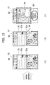
- FIG. 11 is a diagram illustrating a control method of performing a remaining scroll movement after locating an additional content automatically when receiving a scroll movement command beyond a current content screen according to one embodiment of the present invention.
- a post list 900 on a prescribe SNS application is currently output.
- a touch input 10h for scrolling to move the post list 900 is received.
- a preview image 602 of a destination item according to the corresponding touch input 10h can be output to a prescribed region.
- a scroll movement can be performed by 120% of a content screen in consideration of an addible content.
- the controller 180 can scroll to move to the end of the post list 900. Subsequently, as shown in FIG. 11 (c) , an additional content can be automatically loaded on a bottom of the post list 900 (902). Once the additional content is loaded (902), referring to FIG. 11 (d) , the controller 180 can perform the rest of scroll (e.g., additional 20% scroll in the drawing). Meanwhile, the aforementioned control method of setting the index is applicable to an SNS application as well. A state configuration of the control method on the SNS application is described in detail with reference to FIG. 12 and FIG. 13 as follows.
- FIG. 12 is a diagram of state configuration for a method of controlling an index setup on an SNS application according to one embodiment of the present invention.
- a list 900 of post items on an SNS application is currently output through the touchscreen 151.
- a first preview image 602-1 is currently output.
- an index setup command e.g., an input of applying a touch 10q to the first preview image 602-1
- the controller 180 can perform an index setup on a first destination item corresponding to the first preview image 602-1.
- the controller 180 can save an index information on the first destination item.
- the controller 180 can display a first index 701a, which indicates a relative location of the first destination item, on an indication bar 602. After the index information on the first destination item has been saved like FIG. 12 (b) , if a touch drag distance is changed, as mentioned in the foregoing description with reference to FIGs. 6B(a) to 6B(c) , the controller 180 can output a second preview image 602-2 for a second destination item corresponding to the changed distance.
- the controller 180 can display a second index 701b, which indicates a relative location of the second destination item, on the indication bar 602.
- FIG. 13 is a diagram illustrating a control method of facilitating a scroll movement to a prescribed item using a pre-saved index information despite relaunching an SNS application after stopping the SNS application according to one embodiment of the present invention.
- a first index 701a and a second index 701b set in FIG. 12 are currently displayed on the indication bar 602. After the indexes have been set in FIG. 12 , an application is launched again. If an input of selecting one of the first index 701a and the second index 701b is received, the controller 180 can scroll to move to an item indicated by the corresponding index ( FIG. 13 (c) ).
- the controller 180 can scroll to move to a first destination item 801 corresponding to the index information saved in the first index 701a ( FIG. 13 (c) ). Likewise, if the controller 180 scrolls to move to the first destination item 801, the controller 180 can additionally display a scroll movement extent on the indication bar 602 (802).
- embodiments of the present invention provide various effects and/or features. According to at least one of embodiments of the present invention, a considerable amount of scroll command can be easily given. According to at least one of embodiments of the present invention, when a scroll movement is performed, a destination item can be checked in advance.
- Various embodiments may be implemented using a machine-readable medium having instructions stored thereon for execution by a processor to perform various methods presented herein.
- machine-readable mediums include HDD (Hard Disk Drive), SSD (Solid State Disk), SDD (Silicon Disk Drive), ROM, RAM, CD-ROM, a magnetic tape, a floppy disk, an optical data storage device, the other types of storage mediums presented herein, and combinations thereof.
- the machine-readable medium may be realized in the form of a carrier wave (for example, a transmission over the Internet).
- the processor may include the controller 180 of the mobile terminal.
Landscapes
- Engineering & Computer Science (AREA)
- General Engineering & Computer Science (AREA)
- Theoretical Computer Science (AREA)
- Human Computer Interaction (AREA)
- Physics & Mathematics (AREA)
- General Physics & Mathematics (AREA)
- Telephone Function (AREA)
- User Interface Of Digital Computer (AREA)
Applications Claiming Priority (1)
| Application Number | Priority Date | Filing Date | Title |
|---|---|---|---|
| KR1020140129205A KR102252506B1 (ko) | 2014-09-26 | 2014-09-26 | 이동단말기 및 그 제어방법 |
Publications (2)
| Publication Number | Publication Date |
|---|---|
| EP3001299A1 true EP3001299A1 (de) | 2016-03-30 |
| EP3001299B1 EP3001299B1 (de) | 2018-11-07 |
Family
ID=54140198
Family Applications (1)
| Application Number | Title | Priority Date | Filing Date |
|---|---|---|---|
| EP15002642.5A Not-in-force EP3001299B1 (de) | 2014-09-26 | 2015-09-09 | Mobiles endgerät und steuerungsverfahren dafür |
Country Status (4)
| Country | Link |
|---|---|
| US (1) | US10126931B2 (de) |
| EP (1) | EP3001299B1 (de) |
| KR (1) | KR102252506B1 (de) |
| CN (1) | CN105468261B (de) |
Families Citing this family (13)
| Publication number | Priority date | Publication date | Assignee | Title |
|---|---|---|---|---|
| US9785340B2 (en) * | 2014-06-12 | 2017-10-10 | Apple Inc. | Systems and methods for efficiently navigating between applications with linked content on an electronic device with a touch-sensitive display |
| US9648062B2 (en) | 2014-06-12 | 2017-05-09 | Apple Inc. | Systems and methods for multitasking on an electronic device with a touch-sensitive display |
| CN107402706B (zh) * | 2016-05-19 | 2020-09-08 | 北京小米移动软件有限公司 | 手势操作响应方法及装置 |
| JP6569598B2 (ja) * | 2016-05-26 | 2019-09-04 | 京セラドキュメントソリューションズ株式会社 | 表示装置及び表示制御プログラム |
| JP6528726B2 (ja) * | 2016-06-03 | 2019-06-12 | 京セラドキュメントソリューションズ株式会社 | 表示装置及び表示制御プログラム |
| US10891044B1 (en) * | 2016-10-25 | 2021-01-12 | Twitter, Inc. | Automatic positioning of content items in a scrolling display for optimal viewing of the items |
| KR20180136736A (ko) * | 2017-06-15 | 2018-12-26 | 엘지전자 주식회사 | 이동 단말기 |
| US11259088B2 (en) * | 2017-10-27 | 2022-02-22 | Google Llc | Previewing a video in response to computing device interaction |
| CN108491143B (zh) * | 2018-03-23 | 2020-06-30 | 维沃移动通信有限公司 | 一种对象移动控制方法和移动终端 |
| US11966578B2 (en) | 2018-06-03 | 2024-04-23 | Apple Inc. | Devices and methods for integrating video with user interface navigation |
| TWI728361B (zh) * | 2019-05-15 | 2021-05-21 | 和碩聯合科技股份有限公司 | 用於一電子裝置的快速資料瀏覽方法 |
| US11789601B2 (en) * | 2019-11-05 | 2023-10-17 | Dell Products L.P. | System and method for identifying user intent using four-dimensional coordinates of an input pointer |
| KR102791074B1 (ko) * | 2020-10-27 | 2025-04-02 | 삼성에스디에스 주식회사 | 콘텐츠 미리보기 제공 방법 및 그 장치 |
Citations (7)
| Publication number | Priority date | Publication date | Assignee | Title |
|---|---|---|---|---|
| WO2001069369A1 (en) * | 2000-03-17 | 2001-09-20 | Open Tv, Inc. | Method and system for choosing an item out of a list appearing on a screen |
| US20080178116A1 (en) * | 2007-01-19 | 2008-07-24 | Lg Electronics Inc. | Displaying scroll bar on terminal |
| US20100095239A1 (en) * | 2008-10-15 | 2010-04-15 | Mccommons Jordan | Scrollable Preview of Content |
| US20110265002A1 (en) * | 2010-04-21 | 2011-10-27 | Research In Motion Limited | Method of interacting with a scrollable area on a portable electronic device |
| EP2487613A1 (de) * | 2011-02-14 | 2012-08-15 | Sony Mobile Communications AB | Anzeigesteuervorrichtung |
| EP2775386A2 (de) * | 2013-03-08 | 2014-09-10 | Samsung Electronics Co., Ltd. | Elektronische Vorrichtung mit einer Anzeige repräsentativer Informationen und Steuerungsverfahren dafür |
| WO2015184236A1 (en) * | 2014-05-30 | 2015-12-03 | Apple Inc. | Video frame loupe |
Family Cites Families (23)
| Publication number | Priority date | Publication date | Assignee | Title |
|---|---|---|---|---|
| US6204846B1 (en) * | 1999-02-16 | 2001-03-20 | International Business Machines Corporation | Data set user interface control for use in accessing information in a computer |
| US6816174B2 (en) * | 2000-12-18 | 2004-11-09 | International Business Machines Corporation | Method and apparatus for variable density scroll area |
| US20020186252A1 (en) * | 2001-06-07 | 2002-12-12 | International Business Machines Corporation | Method, apparatus and computer program product for providing context to a computer display window |
| US7328411B2 (en) * | 2004-03-19 | 2008-02-05 | Lexmark International, Inc. | Scrollbar enhancement for browsing data |
| GB0417953D0 (en) * | 2004-08-12 | 2004-09-15 | Ibm | A method and apparatus for searching data |
| US7480870B2 (en) * | 2005-12-23 | 2009-01-20 | Apple Inc. | Indication of progress towards satisfaction of a user input condition |
| KR101467766B1 (ko) * | 2008-03-21 | 2014-12-10 | 엘지전자 주식회사 | 이동 단말기 및 이동 단말기의 화면 표시 방법 |
| US20100058240A1 (en) * | 2008-08-26 | 2010-03-04 | Apple Inc. | Dynamic Control of List Navigation Based on List Item Properties |
| KR101620874B1 (ko) * | 2009-05-19 | 2016-05-13 | 삼성전자주식회사 | 목록 검색 방법 및 이를 지원하는 휴대 단말기 |
| US8836648B2 (en) * | 2009-05-27 | 2014-09-16 | Microsoft Corporation | Touch pull-in gesture |
| US20110055753A1 (en) * | 2009-08-31 | 2011-03-03 | Horodezky Samuel J | User interface methods providing searching functionality |
| KR101633332B1 (ko) * | 2009-09-30 | 2016-06-24 | 엘지전자 주식회사 | 단말기 및 그 제어 방법 |
| KR101695813B1 (ko) * | 2010-06-14 | 2017-01-13 | 엘지전자 주식회사 | 이동 단말기 및 그 제어 방법 |
| KR101708821B1 (ko) * | 2010-09-30 | 2017-02-21 | 엘지전자 주식회사 | 이동 단말기 및 그 제어 방법 |
| JP5935267B2 (ja) * | 2011-09-01 | 2016-06-15 | ソニー株式会社 | 情報処理装置、情報処理方法、及びプログラム |
| US10318146B2 (en) * | 2011-09-12 | 2019-06-11 | Microsoft Technology Licensing, Llc | Control area for a touch screen |
| KR101886753B1 (ko) * | 2012-04-05 | 2018-08-08 | 엘지전자 주식회사 | 이동 단말기 및 그것의 제어 방법 |
| US9348501B2 (en) * | 2012-06-14 | 2016-05-24 | Microsoft Technology Licensing, Llc | Touch modes |
| KR20140025940A (ko) * | 2012-08-23 | 2014-03-05 | 삼성전자주식회사 | 터치 시간에 따라 컨텐츠의 페이지 수를 이동시키는 전자 장치 및 방법 |
| KR102107491B1 (ko) * | 2012-08-27 | 2020-05-07 | 삼성전자주식회사 | 리스트 스크롤 바 제어 방법 및 모바일 장치 |
| US9195368B2 (en) * | 2012-09-13 | 2015-11-24 | Google Inc. | Providing radial menus with touchscreens |
| KR102087005B1 (ko) * | 2013-01-31 | 2020-03-11 | 삼성전자 주식회사 | 페이지 검색 방법 및 이를 지원하는 단말기 |
| KR102345343B1 (ko) * | 2014-12-12 | 2021-12-30 | 엘지전자 주식회사 | 인덱스 정보를 디스플레이하는 디지털 디바이스 및 그 제어 방법 |
-
2014
- 2014-09-26 KR KR1020140129205A patent/KR102252506B1/ko not_active Expired - Fee Related
-
2015
- 2015-09-09 EP EP15002642.5A patent/EP3001299B1/de not_active Not-in-force
- 2015-09-15 US US14/855,070 patent/US10126931B2/en not_active Expired - Fee Related
- 2015-09-24 CN CN201510615998.0A patent/CN105468261B/zh not_active Expired - Fee Related
Patent Citations (7)
| Publication number | Priority date | Publication date | Assignee | Title |
|---|---|---|---|---|
| WO2001069369A1 (en) * | 2000-03-17 | 2001-09-20 | Open Tv, Inc. | Method and system for choosing an item out of a list appearing on a screen |
| US20080178116A1 (en) * | 2007-01-19 | 2008-07-24 | Lg Electronics Inc. | Displaying scroll bar on terminal |
| US20100095239A1 (en) * | 2008-10-15 | 2010-04-15 | Mccommons Jordan | Scrollable Preview of Content |
| US20110265002A1 (en) * | 2010-04-21 | 2011-10-27 | Research In Motion Limited | Method of interacting with a scrollable area on a portable electronic device |
| EP2487613A1 (de) * | 2011-02-14 | 2012-08-15 | Sony Mobile Communications AB | Anzeigesteuervorrichtung |
| EP2775386A2 (de) * | 2013-03-08 | 2014-09-10 | Samsung Electronics Co., Ltd. | Elektronische Vorrichtung mit einer Anzeige repräsentativer Informationen und Steuerungsverfahren dafür |
| WO2015184236A1 (en) * | 2014-05-30 | 2015-12-03 | Apple Inc. | Video frame loupe |
Non-Patent Citations (3)
| Title |
|---|
| "Surface 2 User Guide With Windows RT 8.1 Software", 1 March 2014 (2014-03-01), XP055246480, Retrieved from the Internet <URL:http://download.microsoft.com/download/B/D/4/BD44C612-D08E-4586-9345-ACA8AB978BC8/en-us_Surface_2_User_Guide.pdf> [retrieved on 20160201] * |
| AMIT AGARWAL: "YouTube Player with Thumbnails", 8 December 2012 (2012-12-08), XP054976348, Retrieved from the Internet <URL:https://www.youtube.com/watch?v=RW2qPt1_Cf8> [retrieved on 20160203] * |
| DAYLIFE: "Microsoft Surface 2 Review Best Tablet Ever!", 26 October 2013 (2013-10-26), XP054976347, Retrieved from the Internet <URL:https://www.youtube.com/watch?v=9vLkjKxVObA> [retrieved on 20160203] * |
Also Published As
| Publication number | Publication date |
|---|---|
| EP3001299B1 (de) | 2018-11-07 |
| KR102252506B1 (ko) | 2021-05-14 |
| CN105468261A (zh) | 2016-04-06 |
| US10126931B2 (en) | 2018-11-13 |
| US20160092058A1 (en) | 2016-03-31 |
| CN105468261B (zh) | 2020-07-31 |
| KR20160036920A (ko) | 2016-04-05 |
Similar Documents
| Publication | Publication Date | Title |
|---|---|---|
| US10983693B2 (en) | Mobile terminal and controlling method thereof | |
| EP3001299B1 (de) | Mobiles endgerät und steuerungsverfahren dafür | |
| US10628023B2 (en) | Mobile terminal performing a screen scroll function and a method for controlling the mobile terminal | |
| US10001910B2 (en) | Mobile terminal and controlling method thereof for creating shortcut of executing application | |
| US10095787B2 (en) | Mobile terminal and method for controlling the same | |
| US10739940B2 (en) | Mobile terminal for generating a folder by using icons corresponding to applications and method of controlling the same | |
| US10606362B2 (en) | Terminal device and control method | |
| US9904438B2 (en) | Mobile terminal and method for controlling the same | |
| US10101844B2 (en) | Mobile terminal and method of controlling the same based on type of touch object used to apply touch input | |
| US9471267B2 (en) | Mobile terminal and method of controlling the same | |
| US9864486B2 (en) | Mobile terminal and controlling method thereof | |
| US20160139766A1 (en) | Mobile terminal and controlling method thereof | |
| US9798460B2 (en) | Mobile terminal and method for controlling the same | |
| US20180183921A1 (en) | Mobile terminal and method for controlling the same | |
| US20160062609A1 (en) | Mobile terminal and control method thereof | |
| US9294605B1 (en) | Mobile terminal and method for controlling the same | |
| US20170083208A1 (en) | Mobile terminal and control method thereof | |
| US20170277399A1 (en) | Mobile terminal and controlling method thereof | |
| US20170090714A1 (en) | Mobile terminal and method for controlling the same | |
| US20170228131A1 (en) | Mobile terminal and method for controlling the same | |
| US10198170B2 (en) | Mobile terminal and control method therefor | |
| US10671992B2 (en) | Terminal and controlling method thereof | |
| US12267454B2 (en) | Mobile terminal capable of displaying input method editor (IME) and control method for same | |
| US20180052647A1 (en) | Electronic device and method for controlling the same |
Legal Events
| Date | Code | Title | Description |
|---|---|---|---|
| PUAI | Public reference made under article 153(3) epc to a published international application that has entered the european phase |
Free format text: ORIGINAL CODE: 0009012 |
|
| AK | Designated contracting states |
Kind code of ref document: A1 Designated state(s): AL AT BE BG CH CY CZ DE DK EE ES FI FR GB GR HR HU IE IS IT LI LT LU LV MC MK MT NL NO PL PT RO RS SE SI SK SM TR |
|
| AX | Request for extension of the european patent |
Extension state: BA ME |
|
| 17P | Request for examination filed |
Effective date: 20160708 |
|
| STAA | Information on the status of an ep patent application or granted ep patent |
Free format text: STATUS: EXAMINATION IS IN PROGRESS |
|
| 17Q | First examination report despatched |
Effective date: 20161116 |
|
| GRAP | Despatch of communication of intention to grant a patent |
Free format text: ORIGINAL CODE: EPIDOSNIGR1 |
|
| STAA | Information on the status of an ep patent application or granted ep patent |
Free format text: STATUS: GRANT OF PATENT IS INTENDED |
|
| RIC1 | Information provided on ipc code assigned before grant |
Ipc: G06F 3/0485 20130101AFI20180320BHEP Ipc: G06F 3/0486 20130101ALI20180320BHEP Ipc: G06F 3/0488 20130101ALI20180320BHEP Ipc: G06F 3/041 20060101ALI20180320BHEP |
|
| INTG | Intention to grant announced |
Effective date: 20180416 |
|
| GRAS | Grant fee paid |
Free format text: ORIGINAL CODE: EPIDOSNIGR3 |
|
| GRAA | (expected) grant |
Free format text: ORIGINAL CODE: 0009210 |
|
| STAA | Information on the status of an ep patent application or granted ep patent |
Free format text: STATUS: THE PATENT HAS BEEN GRANTED |
|
| AK | Designated contracting states |
Kind code of ref document: B1 Designated state(s): AL AT BE BG CH CY CZ DE DK EE ES FI FR GB GR HR HU IE IS IT LI LT LU LV MC MK MT NL NO PL PT RO RS SE SI SK SM TR |
|
| REG | Reference to a national code |
Ref country code: GB Ref legal event code: FG4D |
|
| REG | Reference to a national code |
Ref country code: CH Ref legal event code: EP Ref country code: AT Ref legal event code: REF Ref document number: 1062882 Country of ref document: AT Kind code of ref document: T Effective date: 20181115 |
|
| REG | Reference to a national code |
Ref country code: DE Ref legal event code: R096 Ref document number: 602015019337 Country of ref document: DE |
|
| REG | Reference to a national code |
Ref country code: IE Ref legal event code: FG4D |
|
| REG | Reference to a national code |
Ref country code: NL Ref legal event code: MP Effective date: 20181107 |
|
| REG | Reference to a national code |
Ref country code: LT Ref legal event code: MG4D |
|
| REG | Reference to a national code |
Ref country code: AT Ref legal event code: MK05 Ref document number: 1062882 Country of ref document: AT Kind code of ref document: T Effective date: 20181107 |
|
| PG25 | Lapsed in a contracting state [announced via postgrant information from national office to epo] |
Ref country code: ES Free format text: LAPSE BECAUSE OF FAILURE TO SUBMIT A TRANSLATION OF THE DESCRIPTION OR TO PAY THE FEE WITHIN THE PRESCRIBED TIME-LIMIT Effective date: 20181107 Ref country code: LV Free format text: LAPSE BECAUSE OF FAILURE TO SUBMIT A TRANSLATION OF THE DESCRIPTION OR TO PAY THE FEE WITHIN THE PRESCRIBED TIME-LIMIT Effective date: 20181107 Ref country code: AT Free format text: LAPSE BECAUSE OF FAILURE TO SUBMIT A TRANSLATION OF THE DESCRIPTION OR TO PAY THE FEE WITHIN THE PRESCRIBED TIME-LIMIT Effective date: 20181107 Ref country code: FI Free format text: LAPSE BECAUSE OF FAILURE TO SUBMIT A TRANSLATION OF THE DESCRIPTION OR TO PAY THE FEE WITHIN THE PRESCRIBED TIME-LIMIT Effective date: 20181107 Ref country code: NO Free format text: LAPSE BECAUSE OF FAILURE TO SUBMIT A TRANSLATION OF THE DESCRIPTION OR TO PAY THE FEE WITHIN THE PRESCRIBED TIME-LIMIT Effective date: 20190207 Ref country code: IS Free format text: LAPSE BECAUSE OF FAILURE TO SUBMIT A TRANSLATION OF THE DESCRIPTION OR TO PAY THE FEE WITHIN THE PRESCRIBED TIME-LIMIT Effective date: 20190307 Ref country code: HR Free format text: LAPSE BECAUSE OF FAILURE TO SUBMIT A TRANSLATION OF THE DESCRIPTION OR TO PAY THE FEE WITHIN THE PRESCRIBED TIME-LIMIT Effective date: 20181107 Ref country code: LT Free format text: LAPSE BECAUSE OF FAILURE TO SUBMIT A TRANSLATION OF THE DESCRIPTION OR TO PAY THE FEE WITHIN THE PRESCRIBED TIME-LIMIT Effective date: 20181107 Ref country code: BG Free format text: LAPSE BECAUSE OF FAILURE TO SUBMIT A TRANSLATION OF THE DESCRIPTION OR TO PAY THE FEE WITHIN THE PRESCRIBED TIME-LIMIT Effective date: 20190207 |
|
| PG25 | Lapsed in a contracting state [announced via postgrant information from national office to epo] |
Ref country code: NL Free format text: LAPSE BECAUSE OF FAILURE TO SUBMIT A TRANSLATION OF THE DESCRIPTION OR TO PAY THE FEE WITHIN THE PRESCRIBED TIME-LIMIT Effective date: 20181107 Ref country code: GR Free format text: LAPSE BECAUSE OF FAILURE TO SUBMIT A TRANSLATION OF THE DESCRIPTION OR TO PAY THE FEE WITHIN THE PRESCRIBED TIME-LIMIT Effective date: 20190208 Ref country code: SE Free format text: LAPSE BECAUSE OF FAILURE TO SUBMIT A TRANSLATION OF THE DESCRIPTION OR TO PAY THE FEE WITHIN THE PRESCRIBED TIME-LIMIT Effective date: 20181107 Ref country code: PT Free format text: LAPSE BECAUSE OF FAILURE TO SUBMIT A TRANSLATION OF THE DESCRIPTION OR TO PAY THE FEE WITHIN THE PRESCRIBED TIME-LIMIT Effective date: 20190307 Ref country code: AL Free format text: LAPSE BECAUSE OF FAILURE TO SUBMIT A TRANSLATION OF THE DESCRIPTION OR TO PAY THE FEE WITHIN THE PRESCRIBED TIME-LIMIT Effective date: 20181107 Ref country code: RS Free format text: LAPSE BECAUSE OF FAILURE TO SUBMIT A TRANSLATION OF THE DESCRIPTION OR TO PAY THE FEE WITHIN THE PRESCRIBED TIME-LIMIT Effective date: 20181107 |
|
| PG25 | Lapsed in a contracting state [announced via postgrant information from national office to epo] |
Ref country code: PL Free format text: LAPSE BECAUSE OF FAILURE TO SUBMIT A TRANSLATION OF THE DESCRIPTION OR TO PAY THE FEE WITHIN THE PRESCRIBED TIME-LIMIT Effective date: 20181107 Ref country code: CZ Free format text: LAPSE BECAUSE OF FAILURE TO SUBMIT A TRANSLATION OF THE DESCRIPTION OR TO PAY THE FEE WITHIN THE PRESCRIBED TIME-LIMIT Effective date: 20181107 Ref country code: IT Free format text: LAPSE BECAUSE OF FAILURE TO SUBMIT A TRANSLATION OF THE DESCRIPTION OR TO PAY THE FEE WITHIN THE PRESCRIBED TIME-LIMIT Effective date: 20181107 Ref country code: DK Free format text: LAPSE BECAUSE OF FAILURE TO SUBMIT A TRANSLATION OF THE DESCRIPTION OR TO PAY THE FEE WITHIN THE PRESCRIBED TIME-LIMIT Effective date: 20181107 |
|
| REG | Reference to a national code |
Ref country code: DE Ref legal event code: R097 Ref document number: 602015019337 Country of ref document: DE |
|
| PG25 | Lapsed in a contracting state [announced via postgrant information from national office to epo] |
Ref country code: SK Free format text: LAPSE BECAUSE OF FAILURE TO SUBMIT A TRANSLATION OF THE DESCRIPTION OR TO PAY THE FEE WITHIN THE PRESCRIBED TIME-LIMIT Effective date: 20181107 Ref country code: RO Free format text: LAPSE BECAUSE OF FAILURE TO SUBMIT A TRANSLATION OF THE DESCRIPTION OR TO PAY THE FEE WITHIN THE PRESCRIBED TIME-LIMIT Effective date: 20181107 Ref country code: EE Free format text: LAPSE BECAUSE OF FAILURE TO SUBMIT A TRANSLATION OF THE DESCRIPTION OR TO PAY THE FEE WITHIN THE PRESCRIBED TIME-LIMIT Effective date: 20181107 Ref country code: SM Free format text: LAPSE BECAUSE OF FAILURE TO SUBMIT A TRANSLATION OF THE DESCRIPTION OR TO PAY THE FEE WITHIN THE PRESCRIBED TIME-LIMIT Effective date: 20181107 |
|
| PLBE | No opposition filed within time limit |
Free format text: ORIGINAL CODE: 0009261 |
|
| STAA | Information on the status of an ep patent application or granted ep patent |
Free format text: STATUS: NO OPPOSITION FILED WITHIN TIME LIMIT |
|
| 26N | No opposition filed |
Effective date: 20190808 |
|
| PG25 | Lapsed in a contracting state [announced via postgrant information from national office to epo] |
Ref country code: SI Free format text: LAPSE BECAUSE OF FAILURE TO SUBMIT A TRANSLATION OF THE DESCRIPTION OR TO PAY THE FEE WITHIN THE PRESCRIBED TIME-LIMIT Effective date: 20181107 |
|
| PG25 | Lapsed in a contracting state [announced via postgrant information from national office to epo] |
Ref country code: TR Free format text: LAPSE BECAUSE OF FAILURE TO SUBMIT A TRANSLATION OF THE DESCRIPTION OR TO PAY THE FEE WITHIN THE PRESCRIBED TIME-LIMIT Effective date: 20181107 |
|
| PG25 | Lapsed in a contracting state [announced via postgrant information from national office to epo] |
Ref country code: MC Free format text: LAPSE BECAUSE OF FAILURE TO SUBMIT A TRANSLATION OF THE DESCRIPTION OR TO PAY THE FEE WITHIN THE PRESCRIBED TIME-LIMIT Effective date: 20181107 |
|
| REG | Reference to a national code |
Ref country code: CH Ref legal event code: PL |
|
| PG25 | Lapsed in a contracting state [announced via postgrant information from national office to epo] |
Ref country code: LU Free format text: LAPSE BECAUSE OF NON-PAYMENT OF DUE FEES Effective date: 20190909 Ref country code: IE Free format text: LAPSE BECAUSE OF NON-PAYMENT OF DUE FEES Effective date: 20190909 Ref country code: LI Free format text: LAPSE BECAUSE OF NON-PAYMENT OF DUE FEES Effective date: 20190930 Ref country code: CH Free format text: LAPSE BECAUSE OF NON-PAYMENT OF DUE FEES Effective date: 20190930 |
|
| REG | Reference to a national code |
Ref country code: BE Ref legal event code: MM Effective date: 20190930 |
|
| PG25 | Lapsed in a contracting state [announced via postgrant information from national office to epo] |
Ref country code: BE Free format text: LAPSE BECAUSE OF NON-PAYMENT OF DUE FEES Effective date: 20190930 |
|
| GBPC | Gb: european patent ceased through non-payment of renewal fee |
Effective date: 20190909 |
|
| PG25 | Lapsed in a contracting state [announced via postgrant information from national office to epo] |
Ref country code: FR Free format text: LAPSE BECAUSE OF NON-PAYMENT OF DUE FEES Effective date: 20190930 Ref country code: GB Free format text: LAPSE BECAUSE OF NON-PAYMENT OF DUE FEES Effective date: 20190909 |
|
| PGFP | Annual fee paid to national office [announced via postgrant information from national office to epo] |
Ref country code: DE Payment date: 20200806 Year of fee payment: 6 |
|
| PG25 | Lapsed in a contracting state [announced via postgrant information from national office to epo] |
Ref country code: CY Free format text: LAPSE BECAUSE OF FAILURE TO SUBMIT A TRANSLATION OF THE DESCRIPTION OR TO PAY THE FEE WITHIN THE PRESCRIBED TIME-LIMIT Effective date: 20181107 |
|
| PG25 | Lapsed in a contracting state [announced via postgrant information from national office to epo] |
Ref country code: HU Free format text: LAPSE BECAUSE OF FAILURE TO SUBMIT A TRANSLATION OF THE DESCRIPTION OR TO PAY THE FEE WITHIN THE PRESCRIBED TIME-LIMIT; INVALID AB INITIO Effective date: 20150909 Ref country code: MT Free format text: LAPSE BECAUSE OF FAILURE TO SUBMIT A TRANSLATION OF THE DESCRIPTION OR TO PAY THE FEE WITHIN THE PRESCRIBED TIME-LIMIT Effective date: 20181107 |
|
| REG | Reference to a national code |
Ref country code: DE Ref legal event code: R119 Ref document number: 602015019337 Country of ref document: DE |
|
| PG25 | Lapsed in a contracting state [announced via postgrant information from national office to epo] |
Ref country code: MK Free format text: LAPSE BECAUSE OF FAILURE TO SUBMIT A TRANSLATION OF THE DESCRIPTION OR TO PAY THE FEE WITHIN THE PRESCRIBED TIME-LIMIT Effective date: 20181107 |
|
| PG25 | Lapsed in a contracting state [announced via postgrant information from national office to epo] |
Ref country code: DE Free format text: LAPSE BECAUSE OF NON-PAYMENT OF DUE FEES Effective date: 20220401 |