EP3002139A1 - Steuerungssystem von stossdämpfern - Google Patents
Steuerungssystem von stossdämpfern Download PDFInfo
- Publication number
- EP3002139A1 EP3002139A1 EP15187847.7A EP15187847A EP3002139A1 EP 3002139 A1 EP3002139 A1 EP 3002139A1 EP 15187847 A EP15187847 A EP 15187847A EP 3002139 A1 EP3002139 A1 EP 3002139A1
- Authority
- EP
- European Patent Office
- Prior art keywords
- vehicle
- time
- roll
- calculation block
- value
- Prior art date
- Legal status (The legal status is an assumption and is not a legal conclusion. Google has not performed a legal analysis and makes no representation as to the accuracy of the status listed.)
- Granted
Links
Images
Classifications
-
- B—PERFORMING OPERATIONS; TRANSPORTING
- B60—VEHICLES IN GENERAL
- B60G—VEHICLE SUSPENSION ARRANGEMENTS
- B60G17/00—Resilient suspensions having means for adjusting the spring or vibration-damper characteristics, for regulating the distance between a supporting surface and a sprung part of vehicle or for locking suspension during use to meet varying vehicular or surface conditions, e.g. due to speed or load
- B60G17/015—Resilient suspensions having means for adjusting the spring or vibration-damper characteristics, for regulating the distance between a supporting surface and a sprung part of vehicle or for locking suspension during use to meet varying vehicular or surface conditions, e.g. due to speed or load the regulating means comprising electric or electronic elements
- B60G17/016—Resilient suspensions having means for adjusting the spring or vibration-damper characteristics, for regulating the distance between a supporting surface and a sprung part of vehicle or for locking suspension during use to meet varying vehicular or surface conditions, e.g. due to speed or load the regulating means comprising electric or electronic elements characterised by their responsiveness, when the vehicle is travelling, to specific motion, a specific condition, or driver input
- B60G17/0162—Resilient suspensions having means for adjusting the spring or vibration-damper characteristics, for regulating the distance between a supporting surface and a sprung part of vehicle or for locking suspension during use to meet varying vehicular or surface conditions, e.g. due to speed or load the regulating means comprising electric or electronic elements characterised by their responsiveness, when the vehicle is travelling, to specific motion, a specific condition, or driver input mainly during a motion involving steering operation, e.g. cornering, overtaking
-
- B—PERFORMING OPERATIONS; TRANSPORTING
- B60—VEHICLES IN GENERAL
- B60G—VEHICLE SUSPENSION ARRANGEMENTS
- B60G17/00—Resilient suspensions having means for adjusting the spring or vibration-damper characteristics, for regulating the distance between a supporting surface and a sprung part of vehicle or for locking suspension during use to meet varying vehicular or surface conditions, e.g. due to speed or load
- B60G17/015—Resilient suspensions having means for adjusting the spring or vibration-damper characteristics, for regulating the distance between a supporting surface and a sprung part of vehicle or for locking suspension during use to meet varying vehicular or surface conditions, e.g. due to speed or load the regulating means comprising electric or electronic elements
- B60G17/016—Resilient suspensions having means for adjusting the spring or vibration-damper characteristics, for regulating the distance between a supporting surface and a sprung part of vehicle or for locking suspension during use to meet varying vehicular or surface conditions, e.g. due to speed or load the regulating means comprising electric or electronic elements characterised by their responsiveness, when the vehicle is travelling, to specific motion, a specific condition, or driver input
-
- B—PERFORMING OPERATIONS; TRANSPORTING
- B60—VEHICLES IN GENERAL
- B60G—VEHICLE SUSPENSION ARRANGEMENTS
- B60G17/00—Resilient suspensions having means for adjusting the spring or vibration-damper characteristics, for regulating the distance between a supporting surface and a sprung part of vehicle or for locking suspension during use to meet varying vehicular or surface conditions, e.g. due to speed or load
- B60G17/015—Resilient suspensions having means for adjusting the spring or vibration-damper characteristics, for regulating the distance between a supporting surface and a sprung part of vehicle or for locking suspension during use to meet varying vehicular or surface conditions, e.g. due to speed or load the regulating means comprising electric or electronic elements
- B60G17/018—Resilient suspensions having means for adjusting the spring or vibration-damper characteristics, for regulating the distance between a supporting surface and a sprung part of vehicle or for locking suspension during use to meet varying vehicular or surface conditions, e.g. due to speed or load the regulating means comprising electric or electronic elements characterised by the use of a specific signal treatment or control method
- B60G17/0182—Resilient suspensions having means for adjusting the spring or vibration-damper characteristics, for regulating the distance between a supporting surface and a sprung part of vehicle or for locking suspension during use to meet varying vehicular or surface conditions, e.g. due to speed or load the regulating means comprising electric or electronic elements characterised by the use of a specific signal treatment or control method involving parameter estimation, e.g. observer, Kalman filter
-
- B—PERFORMING OPERATIONS; TRANSPORTING
- B60—VEHICLES IN GENERAL
- B60G—VEHICLE SUSPENSION ARRANGEMENTS
- B60G2400/00—Indexing codes relating to detected, measured or calculated conditions or factors
- B60G2400/05—Attitude
- B60G2400/051—Angle
- B60G2400/0511—Roll angle
-
- B—PERFORMING OPERATIONS; TRANSPORTING
- B60—VEHICLES IN GENERAL
- B60G—VEHICLE SUSPENSION ARRANGEMENTS
- B60G2400/00—Indexing codes relating to detected, measured or calculated conditions or factors
- B60G2400/05—Attitude
- B60G2400/052—Angular rate
- B60G2400/0521—Roll rate
-
- B—PERFORMING OPERATIONS; TRANSPORTING
- B60—VEHICLES IN GENERAL
- B60G—VEHICLE SUSPENSION ARRANGEMENTS
- B60G2400/00—Indexing codes relating to detected, measured or calculated conditions or factors
- B60G2400/05—Attitude
- B60G2400/053—Angular acceleration
- B60G2400/0531—Roll acceleration
-
- B—PERFORMING OPERATIONS; TRANSPORTING
- B60—VEHICLES IN GENERAL
- B60G—VEHICLE SUSPENSION ARRANGEMENTS
- B60G2400/00—Indexing codes relating to detected, measured or calculated conditions or factors
- B60G2400/20—Speed
- B60G2400/204—Vehicle speed
-
- B—PERFORMING OPERATIONS; TRANSPORTING
- B60—VEHICLES IN GENERAL
- B60G—VEHICLE SUSPENSION ARRANGEMENTS
- B60G2400/00—Indexing codes relating to detected, measured or calculated conditions or factors
- B60G2400/50—Pressure
- B60G2400/51—Pressure in suspension unit
- B60G2400/518—Pressure in suspension unit in damper
- B60G2400/5182—Fluid damper
-
- B—PERFORMING OPERATIONS; TRANSPORTING
- B60—VEHICLES IN GENERAL
- B60G—VEHICLE SUSPENSION ARRANGEMENTS
- B60G2500/00—Indexing codes relating to the regulated action or device
- B60G2500/10—Damping action or damper
-
- B—PERFORMING OPERATIONS; TRANSPORTING
- B60—VEHICLES IN GENERAL
- B60G—VEHICLE SUSPENSION ARRANGEMENTS
- B60G2800/00—Indexing codes relating to the type of movement or to the condition of the vehicle and to the end result to be achieved by the control action
- B60G2800/01—Attitude or posture control
- B60G2800/012—Rolling condition
-
- B—PERFORMING OPERATIONS; TRANSPORTING
- B60—VEHICLES IN GENERAL
- B60G—VEHICLE SUSPENSION ARRANGEMENTS
- B60G2800/00—Indexing codes relating to the type of movement or to the condition of the vehicle and to the end result to be achieved by the control action
- B60G2800/70—Estimating or calculating vehicle parameters or state variables
-
- B—PERFORMING OPERATIONS; TRANSPORTING
- B60—VEHICLES IN GENERAL
- B60G—VEHICLE SUSPENSION ARRANGEMENTS
- B60G2800/00—Indexing codes relating to the type of movement or to the condition of the vehicle and to the end result to be achieved by the control action
- B60G2800/90—System Controller type
- B60G2800/91—Suspension Control
- B60G2800/912—Attitude Control; levelling control
Definitions
- the invention relates to the control of suspension dampers of motor vehicles.
- suspension means including dampers.
- Passive dampers can be used. Passive dampers operate only by reaction to the mechanical stresses generated by body movements. In this case, the depreciation laws are devoid of pilotage. The damping is constant regardless of the conditions of use of the vehicle as long as the mechanical stresses remain constant. The compromise between comfort for the user and vehicle handling is fixed and can not be changed without complex intervention and when the vehicle stops. In other words, the coupling between the suspended mass such as the body and the unsprung masses such as the wheels is immutable whatever the driving situations.
- shock absorber systems offer some discrete levels of damping.
- the number of laws force / speed of the dampers is finished.
- the amplitude of the movements is not taken into account and only particular conditions of conduct can be taken into account punctually.
- Damping control systems have been developed to adapt the vehicle's damping behavior in real time.
- each of the four dampers, or in pairs can then have a damping behavior distinct from the others and continuously modifiable between a minimum value and a maximum value.
- This type of system requires to know with accuracy and in real time the dynamic behavior of the vehicle.
- each component of the roll movements of the vehicle relative to the road on which the wheels are based must be measured and processed in real time.
- sensors for example accelerometers, gyroscopes and gyros.
- these sensors and their wiring are integrated in the vehicle especially to fulfill this function.
- the installation and calibration of each of these sensors are complex and weigh down the vehicle.
- Such a system has a deteriorated reliability with the increase in the number of sensors used.
- the size of the sensors and their connections complicates the design of the vehicles.
- the parameter values may be received during a prior reception step, and may comprise data representative of the longitudinal speed of the vehicle, and / or data representative of the speed of rotation of the steering wheel at time t 0 .
- the order value can be deduced from furthermore a pre-established cartography.
- This method may involve a relatively small number of sensors, or only sensors used or usable by other electronic systems of the vehicle.
- the data made available by these sensors can be shared within the vehicle.
- vehicles already equipped with an ESP system can be equipped with the system described above without any sensor being added.
- This system can be integrated in or include one or more processors, for example a microcontroller, a microprocessor, or other.
- control calculation block may also be able to deduce the time decaying instruction from the value of the command as a function of the pre-established cartography.
- the adaptation of the damping behavior can thus be calibrated more finely according to each vehicle from the design stage. The compromise between comfort and handling holds, for example, until the end of the turn.
- control calculation block can be configured to apply the decay in the time of the value of the command only if the speed of rotation of the steering wheel is within a predefined range for a time included in a range predefined.
- the adaptation of the depreciation is thus prevented in particular situations, for example when parking maneuvers during which a dynamic adaptation of the damping is not desired.
- control calculation block can be configured to apply the decay in time of the control value only if the position of the steering wheel is within a predefined angular range for a period of time within a predefined range .
- control calculation block can be configured to apply the decay in time of the control value only if an average value of the angle speed flying over a time interval, for example a value obtained by integration between the start time and the end time of this time interval, is greater than a threshold value.
- This threshold value may itself be a function of the speed of the vehicle.
- this threshold value can be read in a map associating with longitudinal speed values of the threshold values.
- the system may be devoid of sensor displacement of the vehicle wheels.
- the congested and complex areas of the wheels are devoid of sensors added specifically to power the system.
- the system may be devoid of a sensor able to directly measure the angular position of the vehicle with respect to a longitudinal axis.
- the system can operate without, for example, using gyroscopes that require delicate calibration and have limited responsiveness.
- the preset map may be selectable among several maps available by a command operable by a driver of the vehicle. The depreciation then depends on the choice made by the driver.
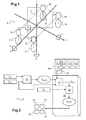
- a vehicle 9 comprises a box 11 shown in dotted lines on the figure 1 , a left front wheel 12, a front right wheel 13, a left rear wheel 14 and a right rear wheel 15.
- the four wheels 12, 13, 14, 15 are connected to the body 11 by means of a corresponding suspension 22, 23, 24, 25.
- Each suspension 22, 23, 24, 25 includes a controllable damper, that is to say whose speed of compression / expansion relative to the force applied to it can be adjusted continuously.
- the dampers are hydraulic and provided with two solenoid valves controlled remotely.
- the mechanical operation of the dampers and the changes in hardness / flexibility of each damper by the play of the solenoid valves is known as such.
- the vehicle 9 When driving, the vehicle 9 is undergoing rolling movements, that is to say the rotation movements about the roll axis x represented by the double arrow referenced by the Greek letter ⁇ .
- the vehicle 9 undergoes pitching movements, that is to say rotational movements around the pitch axis y represented by the double arrow referenced by the Greek letter ⁇ (phi).
- the vehicle 9 undergoes yaw movements, that is to say rotational movements around the yaw axis z represented by the double arrow referenced by the Greek letter ⁇ (psi).
- the vehicle 9 can also undergo pumping movements, that is to say translational movements along the vertical axis z.
- the four aforementioned movements each form a component of the behavior of the body 11 of the vehicle 9 while driving.
- the longitudinal speed of the vehicle 9 corresponds to the first time derivative of the position of the vehicle 9 along the longitudinal axis x with respect to the ground supporting the vehicle 9 and is therefore referenced ⁇ .
- the angular position of the body 11 along the roll axis x is referenced ⁇ .
- the rolling speed, corresponding to the first time derivative of the angular position of roll ⁇ is referenced ⁇ .
- the acceleration of the roll movement, corresponding to the second time derivative of the roll angular position ⁇ and to the first time derivative of the roll speed ⁇ is referenced ⁇ .
- the transverse jerk corresponding to the third time derivative of the roll angular position ⁇ , to the second time derivative of the roll speed ⁇ and to the first time derivative of the acceleration of roll motion ⁇ , is referenced .
- the jerk can also be called “jerk” or “jerk”, or “jolt”, “surge” or “lurch” in English.
- the damper control system 1 comprises a roll forecasting unit 10 and a control calculation block 30.
- the roll forecasting unit 10 and the control calculation block 30 belong here to a dedicated calculator for the dampers 22. , 23, 24, 25.
- the roll forecasting unit 10 and the control calculation block 30 can be integrated into a computer involved in other electronic processes of the vehicle 9.
- a calculator could also be used. form a component of an adaptation of the plate system of the vehicle 9 and / or an element of an anti-lock system (ABS or for "Antiblockiersystem") and / or an element of an electronic correction system of path (or ESP for "Electronic Stability Program ”) .
- An attitude adaptation system is generally considered a slow correction system. Unlike systems Variable damping, it is not intended to adapt to rapid changes in consecutive altitudes of pumping movements, pitching or rolling. The compensation of the load or unloading by vertical movements of the body 11 are usually triggered when the vehicle 9 is stopped. Tare can be manually selected by the driver, be semi-automated, automated or a combination of manual and automatic. Once calibration is done, the variable damping system will control the damping, that is to say the dynamic movements of each damper around its previously calibrated reference position.
- the roll forecasting block 10 and the control calculation block 30 are here connected to a multiplexed network of the vehicle 9, for example a CAN (CAN for "Controller Area Network") network.
- the roll forecasting unit 10 takes from the multiplexed network the signals corresponding to the longitudinal speed ⁇ of the vehicle 9 and to the speed of rotation of the steering wheel ⁇ of the vehicle 9.
- the roll forecasting unit 10 is directly connected to sensors to record the aforementioned data.
- the roll forecasting block 10 may be configured to derive the aforementioned data from the available data.
- the longitudinal velocity ⁇ of the vehicle 9 can be deduced from the rotational speeds of one or more wheels and / or of an engine speed.
- the roll forecasting unit 10 thus receives as input a datum representative of the longitudinal speed ⁇ of the vehicle 9 and a datum representative of the speed of rotation of the steering wheel ⁇ .
- a datum representative of the longitudinal speed ⁇ of the vehicle 9 and a datum representative of the speed of rotation of the steering wheel ⁇ .
- the availability of other state data than those representative of the longitudinal speed ⁇ and the speed of rotation of the flywheel ⁇ are superfluous for the smooth operation of the roll forecasting unit 10 of the system 1.
- the roll forecast block 10 calculates a datum representative of a rolling motion.
- the acceleration of .theta rolling movements is, t1 is estimated at a time t 1 as a function of the data representative of the ⁇ longitudinal speed of the vehicle 9 and the data representative of the rotational speed of the alpha flywheel as of t 0, t 1 being posterior at t 0 .
- the real acceleration of roll movements at time t 1 ( real ⁇ , t1 ) is not measured physically, it results from a calculation estimate and in advance of phase.
- G ⁇ represents the static gain of this transfer function
- ⁇ n its own pulsation
- ⁇ ⁇ its damping coefficient
- the chassis geometry and direction, train characteristics and masses are determined according to the chassis geometry and direction, train characteristics and masses. Such parameters are identified during testing in a development phase according to each vehicle 9.
- the structural parameters can be obtained by calibrating the system 1 with respect to the vehicle 9 in which it is installed. These parameters are pre-established and stored in a memory accessible by the rolling forecast block 10.
- the rolling speed ⁇ at time t 1 can be estimated in phase advance by means of the speed of rotation of the steering wheel ⁇ at time t 0 , where t 1 is later than t 0 .
- the real-time physical measurement of the roll angular position ⁇ of the vehicle 9 is superfluous.
- the roll movements of the body 11 during the rolling of the vehicle 9 are determined in advance of phase. The responsiveness of system 1 is improved.
- Block 10 is furthermore arranged to calculate, from estimated roll speed values ⁇ , a roll acceleration value ⁇ , t1 , by time derivative.
- the control calculation block 30 comprises a control level calculation module 31 receiving as input the data representative of a roll motion, here the acceleration of the roll movements ⁇ is, t1 , resulting from the roll forecast block 10.
- This module 31 also receives as input the speed value of the vehicle ⁇ .
- the module 31 determines a control value K ⁇ , t 1 intended for the dampers 22, 23, 24, 25 of the vehicle 9.
- the module 31 uses a mapping C i .
- the map C i is chosen from several maps C 1 , C 2 , ..., C n .
- the maps C 1 to C n are stored on a memory 40 accessible by the command calculation block 30.
- each mapping C 1 to C n corresponds to a behavior of the set of dampers 22, 23, 24, 25 of the vehicle 9.
- the choice between several maps C 1 to C n makes it possible to adjust the compromise between comfort and handling. .
- these behaviors are predefined between a so-called sports behavior for which the general damping is hard to give priority to the handling of the vehicle, and a so-called comfort behavior for which the damping is flexible so as to limit the transmissions of the vibrations. due to irregularities in the road to the driver.
- the selection among several maps also makes it possible to adapt the behavior of all the dampers 22, 23, 24, 25 to specific conditions of use of the vehicle 9. For example, a distinction is made between the crossing of obstacles such as as very low speed sidewalks and high speed traffic on very regular soils such as a highway.
- the selection of the map C i can be at least partly automated, for example as a function of the longitudinal speed ⁇ of the vehicle 9.
- the control calculation block 30 comprises a control decay control module 32, arranged to then calculate an evolution of the control value as a function of time.
- the module 32 receives as input a data representative of the roll motion residues.
- the residues of roll movements are manifested by the transverse jerk of the vehicle 9 at time t 1 .
- This datum is obtained by time derivation of the value of the transverse acceleration ⁇ t 1 of the body 11 at time t 1 .
- the transverse jerk is a residual roll indicator.
- the module 32 then calculates an evolution of the control value K ⁇ as a function of time. For example, the higher the level of the transverse jerk , is important, plus the decay rate of the control value K ⁇ over time is low, or even zero, and vice versa.
- the evolution of the command value K ⁇ in the course of time can take the form of a decreasing affine line. The value of the slope of such an affine line can be chosen depending on the residues of roll movements
- the slope D defining the decay of the control value K ⁇ over time can be chosen proportional to the roll motion residues.
- the evolution of the control value K ⁇ over time can be determined by the control calculation block 30 not only as a function of the roll motion residues. , but also according to the cartography C i .
- the control calculation block 30 transmits a control signal to each of the dampers 22, 23, 24, 25 generated as a function of the control value K ⁇ ( t ) calculated at a time t.
- the initial control value K ⁇ and / or the function of the control value as a function of time K ⁇ ( t ) can be re-evaluated cyclically.
- Such a system makes it possible to adapt the behavior of the dampers 22, 23, 24, 25 over time, and in particular according to the residues of roll movements. over time.
- the body 11 is subjected to roll movements.
- the damping can be made temporarily harder to oppose the rotation of the body 11 around the axis of roll x. Nevertheless, during the turn, the body 11 reaches a non-zero but balanced angular position of roll ⁇ .
- the system 1 makes it possible to progressively soften the damping when approaching the equilibrium position.
- the variable damping system 1 can be deactivated progressively following the disappearance of the roll movement.
- the depreciation without being in real time in the strict sense, is dynamic and adaptable.
- Such a damping system can be described as semi-active. Unlike a system that would simply delay the application of a damping command, the system 1 adapts to the evolution of the roll.
- alpha terminals A, alpha B, t A, t B of the two aforementioned ranges may be defined according to the selected mapping C i and the vehicle longitudinal speed.
- variable damping system 1 By limiting the activation of the system 1, the inadvertent tripping of the variable damping system is avoided.
- the slow steering wheel movements operated by a driver when the vehicle 9 circulates substantially in a straight line at high speed, for example during a motorway driving does not trigger the activation of the variable damping system 1.
- the roll movements are negligible. It is then useless, or even counterproductive, to adapt the depreciation to reduce such transverse transient movements.
- the steering wheel can be rotated at a high speed for a long time interval. This typically corresponds to a maneuvering phase of the vehicle 9 during which the steering wheel is rotated several times, for example during parking.
- the vehicle 9 has a low speed of movement. The activation of the variable damping system 1 is then irrelevant.
- variable damping system In general, the activation of the variable damping system repeatedly and unsuitably leads to an unnecessary stress on the electronic part of the system 1, but also to a wear of the mechanical components governing the behavior of each of the dampers 22, 23, 24, 25. Such a limitation of activation is therefore optional but advantageous for a long-term reliability of the system 1.
- the block 10 and the module 31 are in advance of phase on the movements of the body, while the module 32 is a function of the residues of the body movements.
- the system 1 combines the prediction of a roll motion in advance of phase to deduce a control value for the dampers 22, 23, 24, 25 of the vehicle 9, and the determination of roll motion residues. in real time to deduce a future evolution of the control value K ⁇ to the dampers 22, 23, 24, 25.
- Such a system not only makes it possible to dispense with direct measurements of the roll position and also makes it possible to to adapt the control a posteriori according to the real behavior of the vehicle over time.
- the presence of certain specific sensors in the vehicle is thus rendered superfluous. In particular, the presence of sensors in specific locations such as near the center of the wheels is avoided.
- Such sensors are generally expensive not only for design and installation but also for maintenance. Moreover, the reliability of their measurements tends to deteriorate over time due to intrinsic wear, vibrations, displacements, etc. This leads to reduce the overall reliability of existing systems.
- the system described above only requires the use of a data representative of the speed of rotation of the steering wheel, a data representative of the longitudinal speed of the vehicle and a data representative of the roll motion residues. of the vehicle.
- data can be measured directly or deduced from conventional sensors and often indispensable elsewhere.
- the speed of rotation of the steering wheel can be obtained by means of a sensor disposed near the steering column.
- the longitudinal speed of the vehicle can be obtained in various ways but is always available in current vehicles.
- the representative data of the roll motion residuals can be deduced by means of a transverse acceleration sensor disposed near the center of gravity of the vehicle.
- Such sensors and the resulting data are generally available in newer vehicles.
- the integration of a system as described above therefore dispenses to integrate new specific sensors, such as those detecting wheel beats for example.
Landscapes
- Engineering & Computer Science (AREA)
- Mechanical Engineering (AREA)
- Vehicle Body Suspensions (AREA)
Applications Claiming Priority (1)
| Application Number | Priority Date | Filing Date | Title |
|---|---|---|---|
| FR1459426A FR3026679B1 (fr) | 2014-10-02 | 2014-10-02 | Systeme de pilotage d'amortisseurs |
Publications (2)
| Publication Number | Publication Date |
|---|---|
| EP3002139A1 true EP3002139A1 (de) | 2016-04-06 |
| EP3002139B1 EP3002139B1 (de) | 2017-06-28 |
Family
ID=52102842
Family Applications (1)
| Application Number | Title | Priority Date | Filing Date |
|---|---|---|---|
| EP15187847.7A Active EP3002139B1 (de) | 2014-10-02 | 2015-10-01 | Steuerungssystem von stossdämpfern |
Country Status (2)
| Country | Link |
|---|---|
| EP (1) | EP3002139B1 (de) |
| FR (1) | FR3026679B1 (de) |
Cited By (2)
| Publication number | Priority date | Publication date | Assignee | Title |
|---|---|---|---|---|
| WO2020182374A1 (en) * | 2019-03-12 | 2020-09-17 | Jaguar Land Rover Limited | Vehicle control system and method |
| CN119704961A (zh) * | 2024-12-31 | 2025-03-28 | 清华大学苏州汽车研究院(吴江) | 一种传感技术和智能算法结合的阻尼控制系统 |
Citations (5)
| Publication number | Priority date | Publication date | Assignee | Title |
|---|---|---|---|---|
| EP0415269A2 (de) * | 1989-08-28 | 1991-03-06 | Toyota Jidosha Kabushiki Kaisha | Drucksteuersystem für Aufhängung |
| EP1623856A2 (de) * | 2004-08-06 | 2006-02-08 | Honda Motor Co., Ltd. | Radaufhängungsregelsystem |
| FR2890902A1 (fr) * | 2005-09-22 | 2007-03-23 | Peugeot Citroen Automobiles Sa | Dispositif de commande de suspension, vehicule muni de celui-ci, procede d'obtention et programme |
| US20120055745A1 (en) * | 2009-02-03 | 2012-03-08 | Silke Buettner | Method for Chassis Control of a Motor Vehicle, and Device for the Performance Thereof |
| FR2971457A1 (fr) | 2011-02-10 | 2012-08-17 | Renault Sa | Procede de pilotage simplifie d'amortisseurs |
-
2014
- 2014-10-02 FR FR1459426A patent/FR3026679B1/fr active Active
-
2015
- 2015-10-01 EP EP15187847.7A patent/EP3002139B1/de active Active
Patent Citations (5)
| Publication number | Priority date | Publication date | Assignee | Title |
|---|---|---|---|---|
| EP0415269A2 (de) * | 1989-08-28 | 1991-03-06 | Toyota Jidosha Kabushiki Kaisha | Drucksteuersystem für Aufhängung |
| EP1623856A2 (de) * | 2004-08-06 | 2006-02-08 | Honda Motor Co., Ltd. | Radaufhängungsregelsystem |
| FR2890902A1 (fr) * | 2005-09-22 | 2007-03-23 | Peugeot Citroen Automobiles Sa | Dispositif de commande de suspension, vehicule muni de celui-ci, procede d'obtention et programme |
| US20120055745A1 (en) * | 2009-02-03 | 2012-03-08 | Silke Buettner | Method for Chassis Control of a Motor Vehicle, and Device for the Performance Thereof |
| FR2971457A1 (fr) | 2011-02-10 | 2012-08-17 | Renault Sa | Procede de pilotage simplifie d'amortisseurs |
Cited By (4)
| Publication number | Priority date | Publication date | Assignee | Title |
|---|---|---|---|---|
| WO2020182374A1 (en) * | 2019-03-12 | 2020-09-17 | Jaguar Land Rover Limited | Vehicle control system and method |
| CN113677545A (zh) * | 2019-03-12 | 2021-11-19 | 捷豹路虎有限公司 | 车辆控制系统和方法 |
| CN113677545B (zh) * | 2019-03-12 | 2023-11-24 | 捷豹路虎有限公司 | 车辆控制系统和方法 |
| CN119704961A (zh) * | 2024-12-31 | 2025-03-28 | 清华大学苏州汽车研究院(吴江) | 一种传感技术和智能算法结合的阻尼控制系统 |
Also Published As
| Publication number | Publication date |
|---|---|
| FR3026679A1 (fr) | 2016-04-08 |
| FR3026679B1 (fr) | 2018-01-19 |
| EP3002139B1 (de) | 2017-06-28 |
Similar Documents
| Publication | Publication Date | Title |
|---|---|---|
| US9694812B2 (en) | Method for determining a target curve incline of a motor vehicle during traveling of a curved roadway section | |
| EP3938260B1 (de) | Verfahren zur erzeugung eines sollwertes für die kombinierte regelung eines radlenksystems und eines differentialbremssystems eines kraftfahrzeuges | |
| CN108791298B (zh) | 用于计算道路摩擦估计值的方法和系统 | |
| CN107406094B (zh) | 用于控制车辆的系统和方法 | |
| US9662974B2 (en) | Torque control for vehicles with independent front and rear propulsion systems | |
| CN109661343A (zh) | 稳定摩托车的系统和方法 | |
| CN107074241A (zh) | 估计车辆侧滑角度的方法、实施所述方法的计算机程序、装载有所述计算机程序的控制单元以及包括所述控制单元的车辆 | |
| JP2019119380A (ja) | 車両、車両運動状態推定装置および車両運動状態推定方法 | |
| CN114340969B (zh) | 状态量计算装置、控制装置及车辆 | |
| CN110290949B (zh) | 悬架控制装置、以及悬架装置 | |
| US20050038588A1 (en) | Vehicle driving force control method | |
| CN110312624B (zh) | 路面判定装置、悬架控制装置、以及悬架装置 | |
| WO2019026298A1 (ja) | サスペンション制御装置、および、サスペンション装置 | |
| JP2023022820A (ja) | 道路車両の車輪のグリップファクタを推定するための装置および方法、ならびに関連道路車両 | |
| EP3002139B1 (de) | Steuerungssystem von stossdämpfern | |
| WO2012127139A1 (fr) | Estimation du rayon dynamique d'une roue et de la vitesse d'un vehicule automobile | |
| US8165769B2 (en) | Multi-factor speed estimation system and method for use | |
| EP3002140B1 (de) | Steuerungssystem von stossdämpfern | |
| FR2890900A1 (fr) | Dispositif de commande de suspension, vehicule muni de celui-ci, procede d'obtention et programme. | |
| WO2019138178A1 (fr) | Procédé de compensation de déviation de trajectoire au freinage avec une direction assistée | |
| EP4370392A1 (de) | Verfahren und vorrichtung zur steuerung des weges eines kraftfahrzeugs, das sich in einer fahrspur fortbewegt, und zugehöriges fahrzeug | |
| FR3097828A1 (fr) | Procédé de régulation de la position latérale d'un véhicule | |
| JP2013086733A (ja) | 車両の駆動力制御装置 | |
| EP1738991B1 (de) | System und Verfahren zur Ansteueren des Einschlagens der Hinterräder eines Fahrzeuges mit Vierradlenkung | |
| EP1883549B1 (de) | Verfahren zur steuerung von mindestens einem stabilisatorstangenantrieb an bord eines fahrzeuges |
Legal Events
| Date | Code | Title | Description |
|---|---|---|---|
| PUAI | Public reference made under article 153(3) epc to a published international application that has entered the european phase |
Free format text: ORIGINAL CODE: 0009012 |
|
| AK | Designated contracting states |
Kind code of ref document: A1 Designated state(s): AL AT BE BG CH CY CZ DE DK EE ES FI FR GB GR HR HU IE IS IT LI LT LU LV MC MK MT NL NO PL PT RO RS SE SI SK SM TR |
|
| AX | Request for extension of the european patent |
Extension state: BA ME |
|
| 17P | Request for examination filed |
Effective date: 20161005 |
|
| RBV | Designated contracting states (corrected) |
Designated state(s): AL AT BE BG CH CY CZ DE DK EE ES FI FR GB GR HR HU IE IS IT LI LT LU LV MC MK MT NL NO PL PT RO RS SE SI SK SM TR |
|
| RIC1 | Information provided on ipc code assigned before grant |
Ipc: B60G 17/018 20060101ALI20161214BHEP Ipc: B60G 17/016 20060101AFI20161214BHEP |
|
| GRAP | Despatch of communication of intention to grant a patent |
Free format text: ORIGINAL CODE: EPIDOSNIGR1 |
|
| INTG | Intention to grant announced |
Effective date: 20170120 |
|
| GRAS | Grant fee paid |
Free format text: ORIGINAL CODE: EPIDOSNIGR3 |
|
| GRAA | (expected) grant |
Free format text: ORIGINAL CODE: 0009210 |
|
| AK | Designated contracting states |
Kind code of ref document: B1 Designated state(s): AL AT BE BG CH CY CZ DE DK EE ES FI FR GB GR HR HU IE IS IT LI LT LU LV MC MK MT NL NO PL PT RO RS SE SI SK SM TR |
|
| REG | Reference to a national code |
Ref country code: GB Ref legal event code: FG4D Free format text: NOT ENGLISH |
|
| REG | Reference to a national code |
Ref country code: CH Ref legal event code: EP |
|
| REG | Reference to a national code |
Ref country code: AT Ref legal event code: REF Ref document number: 904524 Country of ref document: AT Kind code of ref document: T Effective date: 20170715 |
|
| REG | Reference to a national code |
Ref country code: IE Ref legal event code: FG4D Free format text: LANGUAGE OF EP DOCUMENT: FRENCH |
|
| REG | Reference to a national code |
Ref country code: DE Ref legal event code: R096 Ref document number: 602015003316 Country of ref document: DE |
|
| REG | Reference to a national code |
Ref country code: FR Ref legal event code: PLFP Year of fee payment: 3 |
|
| PG25 | Lapsed in a contracting state [announced via postgrant information from national office to epo] |
Ref country code: LT Free format text: LAPSE BECAUSE OF FAILURE TO SUBMIT A TRANSLATION OF THE DESCRIPTION OR TO PAY THE FEE WITHIN THE PRESCRIBED TIME-LIMIT Effective date: 20170628 Ref country code: FI Free format text: LAPSE BECAUSE OF FAILURE TO SUBMIT A TRANSLATION OF THE DESCRIPTION OR TO PAY THE FEE WITHIN THE PRESCRIBED TIME-LIMIT Effective date: 20170628 Ref country code: HR Free format text: LAPSE BECAUSE OF FAILURE TO SUBMIT A TRANSLATION OF THE DESCRIPTION OR TO PAY THE FEE WITHIN THE PRESCRIBED TIME-LIMIT Effective date: 20170628 Ref country code: GR Free format text: LAPSE BECAUSE OF FAILURE TO SUBMIT A TRANSLATION OF THE DESCRIPTION OR TO PAY THE FEE WITHIN THE PRESCRIBED TIME-LIMIT Effective date: 20170929 Ref country code: NO Free format text: LAPSE BECAUSE OF FAILURE TO SUBMIT A TRANSLATION OF THE DESCRIPTION OR TO PAY THE FEE WITHIN THE PRESCRIBED TIME-LIMIT Effective date: 20170928 |
|
| REG | Reference to a national code |
Ref country code: NL Ref legal event code: MP Effective date: 20170628 |
|
| REG | Reference to a national code |
Ref country code: LT Ref legal event code: MG4D |
|
| REG | Reference to a national code |
Ref country code: AT Ref legal event code: MK05 Ref document number: 904524 Country of ref document: AT Kind code of ref document: T Effective date: 20170628 |
|
| PG25 | Lapsed in a contracting state [announced via postgrant information from national office to epo] |
Ref country code: BG Free format text: LAPSE BECAUSE OF FAILURE TO SUBMIT A TRANSLATION OF THE DESCRIPTION OR TO PAY THE FEE WITHIN THE PRESCRIBED TIME-LIMIT Effective date: 20170928 Ref country code: RS Free format text: LAPSE BECAUSE OF FAILURE TO SUBMIT A TRANSLATION OF THE DESCRIPTION OR TO PAY THE FEE WITHIN THE PRESCRIBED TIME-LIMIT Effective date: 20170628 Ref country code: NL Free format text: LAPSE BECAUSE OF FAILURE TO SUBMIT A TRANSLATION OF THE DESCRIPTION OR TO PAY THE FEE WITHIN THE PRESCRIBED TIME-LIMIT Effective date: 20170628 Ref country code: LV Free format text: LAPSE BECAUSE OF FAILURE TO SUBMIT A TRANSLATION OF THE DESCRIPTION OR TO PAY THE FEE WITHIN THE PRESCRIBED TIME-LIMIT Effective date: 20170628 Ref country code: SE Free format text: LAPSE BECAUSE OF FAILURE TO SUBMIT A TRANSLATION OF THE DESCRIPTION OR TO PAY THE FEE WITHIN THE PRESCRIBED TIME-LIMIT Effective date: 20170628 |
|
| PG25 | Lapsed in a contracting state [announced via postgrant information from national office to epo] |
Ref country code: RO Free format text: LAPSE BECAUSE OF FAILURE TO SUBMIT A TRANSLATION OF THE DESCRIPTION OR TO PAY THE FEE WITHIN THE PRESCRIBED TIME-LIMIT Effective date: 20170628 Ref country code: CZ Free format text: LAPSE BECAUSE OF FAILURE TO SUBMIT A TRANSLATION OF THE DESCRIPTION OR TO PAY THE FEE WITHIN THE PRESCRIBED TIME-LIMIT Effective date: 20170628 Ref country code: SK Free format text: LAPSE BECAUSE OF FAILURE TO SUBMIT A TRANSLATION OF THE DESCRIPTION OR TO PAY THE FEE WITHIN THE PRESCRIBED TIME-LIMIT Effective date: 20170628 Ref country code: EE Free format text: LAPSE BECAUSE OF FAILURE TO SUBMIT A TRANSLATION OF THE DESCRIPTION OR TO PAY THE FEE WITHIN THE PRESCRIBED TIME-LIMIT Effective date: 20170628 Ref country code: AT Free format text: LAPSE BECAUSE OF FAILURE TO SUBMIT A TRANSLATION OF THE DESCRIPTION OR TO PAY THE FEE WITHIN THE PRESCRIBED TIME-LIMIT Effective date: 20170628 |
|
| PG25 | Lapsed in a contracting state [announced via postgrant information from national office to epo] |
Ref country code: IS Free format text: LAPSE BECAUSE OF FAILURE TO SUBMIT A TRANSLATION OF THE DESCRIPTION OR TO PAY THE FEE WITHIN THE PRESCRIBED TIME-LIMIT Effective date: 20171028 Ref country code: PL Free format text: LAPSE BECAUSE OF FAILURE TO SUBMIT A TRANSLATION OF THE DESCRIPTION OR TO PAY THE FEE WITHIN THE PRESCRIBED TIME-LIMIT Effective date: 20170628 Ref country code: ES Free format text: LAPSE BECAUSE OF FAILURE TO SUBMIT A TRANSLATION OF THE DESCRIPTION OR TO PAY THE FEE WITHIN THE PRESCRIBED TIME-LIMIT Effective date: 20170628 Ref country code: IT Free format text: LAPSE BECAUSE OF FAILURE TO SUBMIT A TRANSLATION OF THE DESCRIPTION OR TO PAY THE FEE WITHIN THE PRESCRIBED TIME-LIMIT Effective date: 20170628 Ref country code: SM Free format text: LAPSE BECAUSE OF FAILURE TO SUBMIT A TRANSLATION OF THE DESCRIPTION OR TO PAY THE FEE WITHIN THE PRESCRIBED TIME-LIMIT Effective date: 20170628 |
|
| REG | Reference to a national code |
Ref country code: DE Ref legal event code: R097 Ref document number: 602015003316 Country of ref document: DE |
|
| PG25 | Lapsed in a contracting state [announced via postgrant information from national office to epo] |
Ref country code: DK Free format text: LAPSE BECAUSE OF FAILURE TO SUBMIT A TRANSLATION OF THE DESCRIPTION OR TO PAY THE FEE WITHIN THE PRESCRIBED TIME-LIMIT Effective date: 20170628 |
|
| PLBE | No opposition filed within time limit |
Free format text: ORIGINAL CODE: 0009261 |
|
| STAA | Information on the status of an ep patent application or granted ep patent |
Free format text: STATUS: NO OPPOSITION FILED WITHIN TIME LIMIT |
|
| PG25 | Lapsed in a contracting state [announced via postgrant information from national office to epo] |
Ref country code: MC Free format text: LAPSE BECAUSE OF FAILURE TO SUBMIT A TRANSLATION OF THE DESCRIPTION OR TO PAY THE FEE WITHIN THE PRESCRIBED TIME-LIMIT Effective date: 20170628 |
|
| 26N | No opposition filed |
Effective date: 20180329 |
|
| REG | Reference to a national code |
Ref country code: IE Ref legal event code: MM4A |
|
| PG25 | Lapsed in a contracting state [announced via postgrant information from national office to epo] |
Ref country code: LU Free format text: LAPSE BECAUSE OF NON-PAYMENT OF DUE FEES Effective date: 20171001 |
|
| REG | Reference to a national code |
Ref country code: BE Ref legal event code: MM Effective date: 20171031 |
|
| PG25 | Lapsed in a contracting state [announced via postgrant information from national office to epo] |
Ref country code: BE Free format text: LAPSE BECAUSE OF NON-PAYMENT OF DUE FEES Effective date: 20171031 Ref country code: SI Free format text: LAPSE BECAUSE OF FAILURE TO SUBMIT A TRANSLATION OF THE DESCRIPTION OR TO PAY THE FEE WITHIN THE PRESCRIBED TIME-LIMIT Effective date: 20170628 |
|
| PG25 | Lapsed in a contracting state [announced via postgrant information from national office to epo] |
Ref country code: MT Free format text: LAPSE BECAUSE OF FAILURE TO SUBMIT A TRANSLATION OF THE DESCRIPTION OR TO PAY THE FEE WITHIN THE PRESCRIBED TIME-LIMIT Effective date: 20170628 |
|
| REG | Reference to a national code |
Ref country code: FR Ref legal event code: PLFP Year of fee payment: 4 |
|
| PG25 | Lapsed in a contracting state [announced via postgrant information from national office to epo] |
Ref country code: IE Free format text: LAPSE BECAUSE OF NON-PAYMENT OF DUE FEES Effective date: 20171001 |
|
| REG | Reference to a national code |
Ref country code: CH Ref legal event code: PL |
|
| PG25 | Lapsed in a contracting state [announced via postgrant information from national office to epo] |
Ref country code: HU Free format text: LAPSE BECAUSE OF FAILURE TO SUBMIT A TRANSLATION OF THE DESCRIPTION OR TO PAY THE FEE WITHIN THE PRESCRIBED TIME-LIMIT; INVALID AB INITIO Effective date: 20151001 |
|
| PG25 | Lapsed in a contracting state [announced via postgrant information from national office to epo] |
Ref country code: CH Free format text: LAPSE BECAUSE OF NON-PAYMENT OF DUE FEES Effective date: 20181031 Ref country code: LI Free format text: LAPSE BECAUSE OF NON-PAYMENT OF DUE FEES Effective date: 20181031 |
|
| PG25 | Lapsed in a contracting state [announced via postgrant information from national office to epo] |
Ref country code: CY Free format text: LAPSE BECAUSE OF FAILURE TO SUBMIT A TRANSLATION OF THE DESCRIPTION OR TO PAY THE FEE WITHIN THE PRESCRIBED TIME-LIMIT Effective date: 20170628 |
|
| PG25 | Lapsed in a contracting state [announced via postgrant information from national office to epo] |
Ref country code: MK Free format text: LAPSE BECAUSE OF FAILURE TO SUBMIT A TRANSLATION OF THE DESCRIPTION OR TO PAY THE FEE WITHIN THE PRESCRIBED TIME-LIMIT Effective date: 20170628 |
|
| PG25 | Lapsed in a contracting state [announced via postgrant information from national office to epo] |
Ref country code: TR Free format text: LAPSE BECAUSE OF FAILURE TO SUBMIT A TRANSLATION OF THE DESCRIPTION OR TO PAY THE FEE WITHIN THE PRESCRIBED TIME-LIMIT Effective date: 20170628 |
|
| PG25 | Lapsed in a contracting state [announced via postgrant information from national office to epo] |
Ref country code: PT Free format text: LAPSE BECAUSE OF FAILURE TO SUBMIT A TRANSLATION OF THE DESCRIPTION OR TO PAY THE FEE WITHIN THE PRESCRIBED TIME-LIMIT Effective date: 20170628 |
|
| PG25 | Lapsed in a contracting state [announced via postgrant information from national office to epo] |
Ref country code: AL Free format text: LAPSE BECAUSE OF FAILURE TO SUBMIT A TRANSLATION OF THE DESCRIPTION OR TO PAY THE FEE WITHIN THE PRESCRIBED TIME-LIMIT Effective date: 20170628 |
|
| GBPC | Gb: european patent ceased through non-payment of renewal fee |
Effective date: 20191001 |
|
| PG25 | Lapsed in a contracting state [announced via postgrant information from national office to epo] |
Ref country code: GB Free format text: LAPSE BECAUSE OF NON-PAYMENT OF DUE FEES Effective date: 20191001 |
|
| P01 | Opt-out of the competence of the unified patent court (upc) registered |
Effective date: 20230608 |
|
| PGFP | Annual fee paid to national office [announced via postgrant information from national office to epo] |
Ref country code: DE Payment date: 20251021 Year of fee payment: 11 |
|
| PGFP | Annual fee paid to national office [announced via postgrant information from national office to epo] |
Ref country code: FR Payment date: 20251030 Year of fee payment: 11 |