EP3002178A1 - Spurhaltelenkkorrektur mit strassenwölbungs- und seitenwindkompensierung - Google Patents
Spurhaltelenkkorrektur mit strassenwölbungs- und seitenwindkompensierung Download PDFInfo
- Publication number
- EP3002178A1 EP3002178A1 EP15187158.9A EP15187158A EP3002178A1 EP 3002178 A1 EP3002178 A1 EP 3002178A1 EP 15187158 A EP15187158 A EP 15187158A EP 3002178 A1 EP3002178 A1 EP 3002178A1
- Authority
- EP
- European Patent Office
- Prior art keywords
- vehicle
- steering
- correction
- lateral force
- lane
- Prior art date
- Legal status (The legal status is an assumption and is not a legal conclusion. Google has not performed a legal analysis and makes no representation as to the accuracy of the status listed.)
- Withdrawn
Links
Images


Classifications
-
- B—PERFORMING OPERATIONS; TRANSPORTING
- B62—LAND VEHICLES FOR TRAVELLING OTHERWISE THAN ON RAILS
- B62D—MOTOR VEHICLES; TRAILERS
- B62D5/00—Power-assisted or power-driven steering
- B62D5/04—Power-assisted or power-driven steering electrical, e.g. using an electric servo-motor connected to, or forming part of, the steering gear
- B62D5/0457—Power-assisted or power-driven steering electrical, e.g. using an electric servo-motor connected to, or forming part of, the steering gear characterised by control features of the drive means as such
- B62D5/046—Controlling the motor
- B62D5/0466—Controlling the motor for returning the steering wheel to neutral position
-
- B—PERFORMING OPERATIONS; TRANSPORTING
- B62—LAND VEHICLES FOR TRAVELLING OTHERWISE THAN ON RAILS
- B62D—MOTOR VEHICLES; TRAILERS
- B62D6/00—Arrangements for automatically controlling steering depending on driving conditions sensed and responded to, e.g. control circuits
- B62D6/08—Arrangements for automatically controlling steering depending on driving conditions sensed and responded to, e.g. control circuits responsive only to driver input torque
-
- B—PERFORMING OPERATIONS; TRANSPORTING
- B60—VEHICLES IN GENERAL
- B60W—CONJOINT CONTROL OF VEHICLE SUB-UNITS OF DIFFERENT TYPE OR DIFFERENT FUNCTION; CONTROL SYSTEMS SPECIALLY ADAPTED FOR HYBRID VEHICLES; ROAD VEHICLE DRIVE CONTROL SYSTEMS FOR PURPOSES NOT RELATED TO THE CONTROL OF A PARTICULAR SUB-UNIT
- B60W10/00—Conjoint control of vehicle sub-units of different type or different function
- B60W10/20—Conjoint control of vehicle sub-units of different type or different function including control of steering systems
-
- B—PERFORMING OPERATIONS; TRANSPORTING
- B60—VEHICLES IN GENERAL
- B60W—CONJOINT CONTROL OF VEHICLE SUB-UNITS OF DIFFERENT TYPE OR DIFFERENT FUNCTION; CONTROL SYSTEMS SPECIALLY ADAPTED FOR HYBRID VEHICLES; ROAD VEHICLE DRIVE CONTROL SYSTEMS FOR PURPOSES NOT RELATED TO THE CONTROL OF A PARTICULAR SUB-UNIT
- B60W30/00—Purposes of road vehicle drive control systems not related to the control of a particular sub-unit, e.g. of systems using conjoint control of vehicle sub-units
- B60W30/02—Control of vehicle driving stability
-
- B—PERFORMING OPERATIONS; TRANSPORTING
- B60—VEHICLES IN GENERAL
- B60W—CONJOINT CONTROL OF VEHICLE SUB-UNITS OF DIFFERENT TYPE OR DIFFERENT FUNCTION; CONTROL SYSTEMS SPECIALLY ADAPTED FOR HYBRID VEHICLES; ROAD VEHICLE DRIVE CONTROL SYSTEMS FOR PURPOSES NOT RELATED TO THE CONTROL OF A PARTICULAR SUB-UNIT
- B60W30/00—Purposes of road vehicle drive control systems not related to the control of a particular sub-unit, e.g. of systems using conjoint control of vehicle sub-units
- B60W30/02—Control of vehicle driving stability
- B60W30/045—Improving turning performance
-
- B—PERFORMING OPERATIONS; TRANSPORTING
- B60—VEHICLES IN GENERAL
- B60W—CONJOINT CONTROL OF VEHICLE SUB-UNITS OF DIFFERENT TYPE OR DIFFERENT FUNCTION; CONTROL SYSTEMS SPECIALLY ADAPTED FOR HYBRID VEHICLES; ROAD VEHICLE DRIVE CONTROL SYSTEMS FOR PURPOSES NOT RELATED TO THE CONTROL OF A PARTICULAR SUB-UNIT
- B60W30/00—Purposes of road vehicle drive control systems not related to the control of a particular sub-unit, e.g. of systems using conjoint control of vehicle sub-units
- B60W30/10—Path keeping
-
- B—PERFORMING OPERATIONS; TRANSPORTING
- B60—VEHICLES IN GENERAL
- B60W—CONJOINT CONTROL OF VEHICLE SUB-UNITS OF DIFFERENT TYPE OR DIFFERENT FUNCTION; CONTROL SYSTEMS SPECIALLY ADAPTED FOR HYBRID VEHICLES; ROAD VEHICLE DRIVE CONTROL SYSTEMS FOR PURPOSES NOT RELATED TO THE CONTROL OF A PARTICULAR SUB-UNIT
- B60W30/00—Purposes of road vehicle drive control systems not related to the control of a particular sub-unit, e.g. of systems using conjoint control of vehicle sub-units
- B60W30/10—Path keeping
- B60W30/12—Lane keeping
-
- B—PERFORMING OPERATIONS; TRANSPORTING
- B60—VEHICLES IN GENERAL
- B60W—CONJOINT CONTROL OF VEHICLE SUB-UNITS OF DIFFERENT TYPE OR DIFFERENT FUNCTION; CONTROL SYSTEMS SPECIALLY ADAPTED FOR HYBRID VEHICLES; ROAD VEHICLE DRIVE CONTROL SYSTEMS FOR PURPOSES NOT RELATED TO THE CONTROL OF A PARTICULAR SUB-UNIT
- B60W30/00—Purposes of road vehicle drive control systems not related to the control of a particular sub-unit, e.g. of systems using conjoint control of vehicle sub-units
- B60W30/18—Propelling the vehicle
- B60W30/18009—Propelling the vehicle related to particular drive situations
- B60W30/18145—Cornering
-
- B—PERFORMING OPERATIONS; TRANSPORTING
- B62—LAND VEHICLES FOR TRAVELLING OTHERWISE THAN ON RAILS
- B62D—MOTOR VEHICLES; TRAILERS
- B62D15/00—Steering not otherwise provided for
- B62D15/02—Steering position indicators ; Steering position determination; Steering aids
- B62D15/025—Active steering aids, e.g. helping the driver by actively influencing the steering system after environment evaluation
-
- B—PERFORMING OPERATIONS; TRANSPORTING
- B62—LAND VEHICLES FOR TRAVELLING OTHERWISE THAN ON RAILS
- B62D—MOTOR VEHICLES; TRAILERS
- B62D6/00—Arrangements for automatically controlling steering depending on driving conditions sensed and responded to, e.g. control circuits
- B62D6/04—Arrangements for automatically controlling steering depending on driving conditions sensed and responded to, e.g. control circuits responsive only to forces disturbing the intended course of the vehicle, e.g. forces acting transversely to the direction of vehicle travel
-
- B—PERFORMING OPERATIONS; TRANSPORTING
- B60—VEHICLES IN GENERAL
- B60W—CONJOINT CONTROL OF VEHICLE SUB-UNITS OF DIFFERENT TYPE OR DIFFERENT FUNCTION; CONTROL SYSTEMS SPECIALLY ADAPTED FOR HYBRID VEHICLES; ROAD VEHICLE DRIVE CONTROL SYSTEMS FOR PURPOSES NOT RELATED TO THE CONTROL OF A PARTICULAR SUB-UNIT
- B60W2420/00—Indexing codes relating to the type of sensors based on the principle of their operation
- B60W2420/40—Photo, light or radio wave sensitive means, e.g. infrared sensors
- B60W2420/403—Image sensing, e.g. optical camera
-
- B—PERFORMING OPERATIONS; TRANSPORTING
- B60—VEHICLES IN GENERAL
- B60W—CONJOINT CONTROL OF VEHICLE SUB-UNITS OF DIFFERENT TYPE OR DIFFERENT FUNCTION; CONTROL SYSTEMS SPECIALLY ADAPTED FOR HYBRID VEHICLES; ROAD VEHICLE DRIVE CONTROL SYSTEMS FOR PURPOSES NOT RELATED TO THE CONTROL OF A PARTICULAR SUB-UNIT
- B60W2520/00—Input parameters relating to overall vehicle dynamics
- B60W2520/10—Longitudinal speed
-
- B—PERFORMING OPERATIONS; TRANSPORTING
- B60—VEHICLES IN GENERAL
- B60W—CONJOINT CONTROL OF VEHICLE SUB-UNITS OF DIFFERENT TYPE OR DIFFERENT FUNCTION; CONTROL SYSTEMS SPECIALLY ADAPTED FOR HYBRID VEHICLES; ROAD VEHICLE DRIVE CONTROL SYSTEMS FOR PURPOSES NOT RELATED TO THE CONTROL OF A PARTICULAR SUB-UNIT
- B60W2540/00—Input parameters relating to occupants
- B60W2540/18—Steering angle
-
- B—PERFORMING OPERATIONS; TRANSPORTING
- B60—VEHICLES IN GENERAL
- B60W—CONJOINT CONTROL OF VEHICLE SUB-UNITS OF DIFFERENT TYPE OR DIFFERENT FUNCTION; CONTROL SYSTEMS SPECIALLY ADAPTED FOR HYBRID VEHICLES; ROAD VEHICLE DRIVE CONTROL SYSTEMS FOR PURPOSES NOT RELATED TO THE CONTROL OF A PARTICULAR SUB-UNIT
- B60W2552/00—Input parameters relating to infrastructure
- B60W2552/20—Road profile, i.e. the change in elevation or curvature of a plurality of continuous road segments
-
- B—PERFORMING OPERATIONS; TRANSPORTING
- B60—VEHICLES IN GENERAL
- B60W—CONJOINT CONTROL OF VEHICLE SUB-UNITS OF DIFFERENT TYPE OR DIFFERENT FUNCTION; CONTROL SYSTEMS SPECIALLY ADAPTED FOR HYBRID VEHICLES; ROAD VEHICLE DRIVE CONTROL SYSTEMS FOR PURPOSES NOT RELATED TO THE CONTROL OF A PARTICULAR SUB-UNIT
- B60W2556/00—Input parameters relating to data
- B60W2556/45—External transmission of data to or from the vehicle
- B60W2556/50—External transmission of data to or from the vehicle of positioning data, e.g. GPS [Global Positioning System] data
-
- B—PERFORMING OPERATIONS; TRANSPORTING
- B60—VEHICLES IN GENERAL
- B60W—CONJOINT CONTROL OF VEHICLE SUB-UNITS OF DIFFERENT TYPE OR DIFFERENT FUNCTION; CONTROL SYSTEMS SPECIALLY ADAPTED FOR HYBRID VEHICLES; ROAD VEHICLE DRIVE CONTROL SYSTEMS FOR PURPOSES NOT RELATED TO THE CONTROL OF A PARTICULAR SUB-UNIT
- B60W2710/00—Output or target parameters relating to a particular sub-units
- B60W2710/20—Steering systems
- B60W2710/202—Steering torque
Definitions
- This disclosure generally relates to vehicle steering assistance, and more particularly relates providing a steering correction to steer the vehicle toward a center of the roadway lane based on a steering torque signal to compensate for road camber and crosswinds.
- LDP lane departure prevention
- Road camber or road surface crowning (or similarly super-elevation or road banking) is present on many roadways to drain surface water away from the roadway lanes.
- the camber angle can change depending on the lane being occupied, and as different sections of the roadway are traveled, so it is variable and can influence a vehicle's reaction to an automated steering correction.
- Crosswinds also place a lateral force on the vehicle that can influence a vehicle's reaction to an automated steering correction.
- Compensating a steering correction for road camber and crosswinds using yaw and lateral acceleration signals has been proposed, but poor signal-to-noise ratios and lagging sensor response times have limited the performance improvement when using these sensors.
- An improved way to compensate LDP system steering corrections for variations in road camber and crosswinds is needed.
- Described herein are a system and a method for providing a steering correction to assist an operator of a vehicle with steering the vehicle to keep the vehicle in the center of a roadway lane.
- a measured torque present in the steering mechanism is used to compensate the steering correction for a lateral force experienced by the vehicle due to, for example, roadway camber and/or crosswind.
- a steering assist system configured to assist an operator to steer a vehicle.
- the system includes a torque sensor, a location device, and a controller.
- the torque sensor is configured to output a torque signal indicative of a lateral force experienced by the vehicle.
- the location device is configured to determine a lateral position of the vehicle relative to a roadway.
- the controller configured to determine a steering correction to steer the vehicle toward a center of a roadway lane. The steering correction is based on the torque signal and the lateral position.
- a baseline-correction-magnitude of the steering correction is increased when the steering correction is directed in opposition to the lateral force, and is decreased when the steering correction is directed in cooperation with the lateral force.
- a method of assisting an operator to steer a vehicle includes the step of receiving a torque signal from a torque sensor.
- the torque signal is indicative of a lateral force experienced by the vehicle.
- the method also includes the step of determining a lateral position of the vehicle relative to a roadway lane.
- the method also includes the step of determining a steering correction to steer the vehicle toward a center of the roadway lane. The steering correction is based on the torque signal and the lateral position.
- determining the steering correction includes increasing a baseline-correction-magnitude when the steering correction is directed in opposition to the lateral force, and decreasing the baseline-correction-magnitude when the steering correction is directed in cooperation with the lateral force.
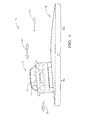
- Fig. 1 illustrates a non-limiting example of a vehicle 10 equipped with a steering assist system, hereafter referred to as the system 12.
- the system 12 is configured to assist an operator 14 to steer the vehicle 10 along a roadway 16.
- the system 12 is particularly configured to assist the operator 14 with keeping the vehicle 10 centered in a particular roadway lane, for example a left lane 18L or a right lane 18R.
- Roadways are often crowned so that water drains off the roadway.
- the angle or camber of a lane in cooperation with gravity, will typically cause the vehicle 10 to experience a lateral force 20.
- the vehicle 10 is traveling in the left lane 18L, and the camber of the left lane 18L is such that the lateral force 20 is directed to the left. If the vehicle 10 were traveling in the right lane 18R, then the lateral force caused by the camber of the right lane 18R would be directed to the right.
- the vehicle 10 may be subjected to a crosswind 22 that can also cause the vehicle to experience a lateral force.
- the forces caused by the camber of the left lane 18L and the crosswind 22 may combine to increase the magnitude of the lateral force 20.
- the lateral force due to gravity would be directed against the lateral force due to the crosswind 22, so the magnitude of the lateral force experienced by the vehicle 10 may be reduced, or the opposing forces may possibly cancel each other.
- Fig. 2 illustrates a non-limiting example of the system 12 which is understood to be installed in the vehicle 12.
- the system 12 includes a torque sensor configured to output a torque signal 26 indicative of the lateral force 20 experienced by the vehicle 10.
- the hand-wheel 28 is mechanically coupled to the steering-wheels 30 by, for example, a steering shaft, as will be recognized by those in the art.
- the torque sensor 24 may be configured to determine a steering torque 32 applied to the hand-wheel 28 of the vehicle 10 by an operator 14 of the vehicle 10 in opposition to the lateral force 20.
- the lateral force 20 experienced by the vehicle 10 causes the operator 14 to exert or apply the steering torque 32 to the hand-wheel 28 so that the vehicle 10 travels along or toward the center of the lane occupied by the vehicle 10.
- the torque signal 26 can be used as an indicator of the direction and magnitude of the lateral force 20.
- the operator 14 can be characterized as being part of the system 12, which is sometimes referred to as a driver-in-the-loop system. Even if the vehicle 10 is equipped with hydraulic type power steering, the operator 14 will still need to apply a relatively constant steering torque to keep the vehicle centered in the lane, and a measurement of this steering torque can be used as an indicator of the lateral load.
- EPS electric power steering
- a steering box 36 may be equipped with a torque sensor similar to the torque sensor 24, and configured to output a torque signal 26A indicative of the lateral force 20.
- the steering actuator 34 may be configured to output a torque signal 26B based on a torque sensor within the steering actuator 34, or based on the amount of current applied to an electric steering actuator (not shown) within the steering actuator 34. Either way, the system 12 is able to determine an indication of the lateral force 20.
- the lateral force may be determined by a torque sensor configured to determine a steering torque 32A applied to the steering box 36 of the vehicle by the steering actuator 34 of the vehicle 10 in opposition to the lateral force 20.
- the system 12 includes a location device 40 configured to determine a lateral position 42 ( Fig. 1 ) of the vehicle relative to a roadway lane (e.g. the left lane 18L or the right lane 18R).
- information about the lateral position may also include information related to the rate at which the vehicle 10 is departing from the center of the roadway lane which is also known as lateral rate.
- the location device 40 may be an imaging device (i.e. a camera) configured to detect the location of objects (not shown) along the roadway suitable for determining the lateral position 42 of the vehicle.
- the suitable objects may include lane markers (i.e.
- the roadway 16 may be equipped with devices that can't be readily seen, but are detectable by equipment known in the automated steering arts.
- the locating device may include a global positioning system (GPS) device and/or electronic horizon systems (provides information about the road ahead of the present position) configured to determine the lateral position 42 of the vehicle 10. It is contemplated that automated driving systems will use, but will not be limited to, a combination of the alternatives described above to determine the lateral position 42 of the vehicle 10.
- the location device 40 may be configured to output a location signal 44 indicative of a distance and direction that the vehicle 10 is located relative to the center of the roadway lane on which the vehicle is traveling, i.e. how far offset from the center of the left lane 18L that the vehicle 10 is positioned.
- the location signal 44 may also include information about the lateral rate that the vehicle 10 is moving laterally toward or away from the center of the roadway lane.
- Other ways to indicate the lateral position 42 are contemplated, but distance and direction to the center of the lane is presented here only to simplify the explanation of the system 12 described herein.
- the system 12 may include a controller 48 configured receive the torque signal 26 (or 26A or 26B) and the position signal 44, and to determine a steering correction 46 to steer the vehicle toward a center of the roadway-lane 18 (e.g. the left lane 18L or the right lane 18R).
- the steering correction 46 may result in a reduction of the steering torque 32 needed to steer the vehicle 10 toward a center of the roadway-lane 18, or may momentarily take control of steering the vehicle 10 until the vehicle 10 is near the center of the roadway-lane 18.
- the controller 48 may include a processor (not shown) such as a microprocessor or other control circuitry such as analog and/or digital control circuitry including an application specific integrated circuit (ASIC) for processing data as should be evident to those in the art.
- ASIC application specific integrated circuit
- the controller 48 may include memory, including non-volatile memory, such as electrically erasable programmable read-only memory (EEPROM) for storing one or more routines, thresholds and captured data.
- EEPROM electrically erasable programmable read-only memory
- the one or more routines may be executed by the processor to perform steps for assisting the operator 14 with steering the vehicle 10 as described herein.
- Fig. 3 illustrates a non-limiting example of a graph 50 of the steering correction 46 ( Fig. 2 ) output by the controller 48 or provided by the system 12 at varying lateral positions for system configurations with and without camber/crosswind compensation.
- the baseline correction 52 is comparable to the steering correction 46 output by the system 12 when the roadway is level (i.e. no camber) and there are no cross winds.
- the compensated correction 54 is an example of the steering correction 46 at various lateral positions assuming a constant value for the lateral force 20. That is, the baseline-correction-magnitude is the steering correction that would be applied by a lane departure correction system that did not have knowledge of the lateral force 20 because the system did not have a torque sensor or the like.
- baseline-correction-magnitude 46A of the steering correction is decreased when the steering correction is directed in cooperation with the lateral force 20, and baseline-correction-magnitude 46B is increased when the steering correction is directed in opposition to the lateral force.
- the system 12 may also define a dead-band 56 where no steering correction is performed by the system 12 if the vehicle is close to the center of the roadway lane 18.
- the width of baseline dead-band (portion of the x-axis between where the baseline correction 52 intersects the x-axis) may be varied in accordance with, but not limited to, vehicle speed or the width of the roadway lane 18. If a lateral force 20 is detected, then the compensated correction 54 shifts the dead-band 56 along the x-axis as illustrated.
- the steering correction 46 defines or includes a dead-band 56 based on the torque signal 26 and the lateral position 42.
- Fig. 4 illustrates a non-limiting example of a method 400 of assisting an operator to steer a vehicle 10.
- the method 400 is used, in cooperation with the system 12, to vary an amount of steering effort assistance provided to an operator 14 of the vehicle 10 to help keep the vehicle 10 in or toward the center of a roadway-lane 18.
- the amount of assistance may vary from merely increasing the power assistance level to providing enough effort to actually steer the vehicle independent of the operator's actions.
- Step 410, RECEIVE TORQUE SIGNAL may include receiving a torque signal 26, or 26A, or 26B from a torque sensor 24, or a steering actuator 34, or a steering box 36, respectively.
- the torque signals 26, 26A, 26B are indicative of a lateral force 20 experienced by the vehicle 10.
- Step 420, DETERMINE LATERAL POSITION may include determining a lateral position 42, which may include a lateral rate, of the vehicle relative to a roadway lane.
- An imaging device such as a camera may be used to determine the position of the vehicle 10 relative to roadway markers such as lines painted on the roadway 16, or other objects such a guardrails proximate to the roadway 16.
- GPS may be used to determine the lateral position 42.
- Steps 430-460 cooperate to determine a steering correction to steer the vehicle toward a center of the roadway lane, where the steering correction is based on the torque signal and the lateral position from steps 410 and 420.
- Step 430 DETERMINE BASELINE-CORRECTION-MAGNITUDE, may include using lateral position 42 by itself to determine a base-line correction magnitude necessary to assist the operator and/or autonomously steer the vehicle 10 to the center of the left lane 18L for the situation illustrated in Fig. 1 .
- Other signals that may be used to determine a base-line correction magnitude include, but are not limited to a turn signal, accelerator pedal, and brake pedal operation, validity of the lane markers, map database matching, and electronic horizon information. Additional information other than lateral position may be used to anticipate steering corrections needed for upcoming curves, banking, exit ramps, etc. that could further draw lateral force information.
- Step 440 STEERING CORRECTION OPPOSED TO LATERAL FORCE?, may include comparing the direction of the lateral force 20 to the lateral position 42. If the direction of the steering correction 46 is against or in opposition to the lateral force 20 (YES), then the method 400 proceeds to step 450. Otherwise (NO), the method 400 proceeded to step 460.
- Step 450 INCREASE BASELINE-CORRECTION-MAGNITUDE, may include increasing a baseline-correction-magnitude when the steering correction is directed in opposition to the lateral force
- Step 460 DECREASE BASELINE-CORRECTION-MAGNITUDE, may include decreasing the baseline-correction-magnitude when the steering correction is directed in cooperation with the lateral force
- a steering assist system (the system 12), a controller 48 for the system 12, and a method 400 to assist an operator to steer a vehicle is provided.
- a steering assist system (the system 12), a controller 48 for the system 12, and a method 400 to assist an operator to steer a vehicle is provided.
Landscapes
- Engineering & Computer Science (AREA)
- Transportation (AREA)
- Mechanical Engineering (AREA)
- Chemical & Material Sciences (AREA)
- Combustion & Propulsion (AREA)
- Automation & Control Theory (AREA)
- Steering Control In Accordance With Driving Conditions (AREA)
Applications Claiming Priority (1)
| Application Number | Priority Date | Filing Date | Title |
|---|---|---|---|
| US14/505,781 US20160096546A1 (en) | 2014-10-03 | 2014-10-03 | Lane departure steering correction with road camber and crosswind compensation |
Publications (1)
| Publication Number | Publication Date |
|---|---|
| EP3002178A1 true EP3002178A1 (de) | 2016-04-06 |
Family
ID=54207418
Family Applications (1)
| Application Number | Title | Priority Date | Filing Date |
|---|---|---|---|
| EP15187158.9A Withdrawn EP3002178A1 (de) | 2014-10-03 | 2015-09-28 | Spurhaltelenkkorrektur mit strassenwölbungs- und seitenwindkompensierung |
Country Status (3)
| Country | Link |
|---|---|
| US (1) | US20160096546A1 (de) |
| EP (1) | EP3002178A1 (de) |
| CN (1) | CN105480295A (de) |
Cited By (5)
| Publication number | Priority date | Publication date | Assignee | Title |
|---|---|---|---|---|
| EP3248857A1 (de) * | 2016-05-23 | 2017-11-29 | Delphi Technologies, Inc. | Spurhaltesystem für autonomes fahrzeug in windigen bedingungen |
| CN109835410A (zh) * | 2017-11-28 | 2019-06-04 | 湖南中车时代电动汽车股份有限公司 | 一种车辆行驶的经验数据提取方法及相关装置 |
| WO2020120043A1 (de) * | 2018-12-14 | 2020-06-18 | Robert Bosch Gmbh | Verfahren zur vorbereitung und/oder durchführung eines den fahrer eines fahrzeuges unterstützenden lenkeingriffes |
| WO2020244841A1 (fr) * | 2019-06-06 | 2020-12-10 | Renault S.A.S | Procédé de calcul de la position latérale d'un véhicule automobile |
| RU2800838C2 (ru) * | 2019-06-06 | 2023-07-31 | Рено С.А.С | Способ вычисления бокового положения автотранспортного средства |
Families Citing this family (17)
| Publication number | Priority date | Publication date | Assignee | Title |
|---|---|---|---|---|
| KR101622028B1 (ko) * | 2014-07-17 | 2016-05-17 | 주식회사 만도 | 차량 통신을 이용한 차량 제어 장치 및 제어 방법 |
| JP6332167B2 (ja) * | 2015-06-26 | 2018-05-30 | 株式会社デンソー | 車線維持支援装置 |
| FR3051426B1 (fr) * | 2016-05-19 | 2022-01-07 | Renault Sas | Procede de correction de la trajectoire d'un vehicule automobile par detection de marquages routiers au sol. |
| US10179607B2 (en) * | 2016-08-03 | 2019-01-15 | Aptiv Technologies Limited | Lane keeping system for autonomous vehicle in wind conditions using vehicle roll |
| US10150474B2 (en) * | 2017-01-04 | 2018-12-11 | Robert Bosch Gmbh | Reducing lateral position deviation during an automated lane change |
| KR102042946B1 (ko) * | 2017-03-30 | 2019-11-08 | 바이두닷컴 타임즈 테크놀로지(베이징) 컴퍼니 리미티드 | 자율 주행 차량을 위한 감속 연석 기반 방향 검출 및 차선 유지 시스템 |
| JP6596043B2 (ja) * | 2017-07-31 | 2019-10-23 | 株式会社Subaru | 車両の走行制御システム |
| CN108535031B (zh) * | 2018-04-09 | 2020-08-14 | 江苏农牧科技职业学院 | 一种农用装载车转向校正系统及方法 |
| JP7147344B2 (ja) * | 2018-08-06 | 2022-10-05 | マツダ株式会社 | 車両制御装置および車両制御方法 |
| CN112498345B (zh) * | 2019-08-26 | 2022-08-02 | 上海汽车集团股份有限公司 | 一种处理方法及装置 |
| US11332136B2 (en) * | 2019-12-06 | 2022-05-17 | Continental Autonomous Mobility US, LLC | Automated vehicle lane positioning |
| CN111196274B (zh) * | 2020-01-21 | 2021-07-06 | 重庆长安汽车股份有限公司 | 车辆倾斜道路对中控制的方法、系统、存储介质及车辆 |
| CN112232111B (zh) * | 2020-09-01 | 2024-04-26 | 杭州鸿泉物联网技术股份有限公司 | 商砼车搅拌筒转向监测方法、系统、电子设备与存储介质 |
| EP4353556B1 (de) * | 2021-06-11 | 2025-12-17 | Nissan Motor Co., Ltd. | Fahrzeugsteuerungsverfahren und fahrzeugsteuerungsvorrichtung |
| CN114013500A (zh) * | 2021-11-24 | 2022-02-08 | 一汽奔腾轿车有限公司 | 一种基于电动转向抑制汽车跑偏的控制方法 |
| CN116605216A (zh) * | 2023-06-27 | 2023-08-18 | 英博超算(南京)科技有限公司 | 一种斜坡路面的车辆控制方法 |
| KR20250176399A (ko) * | 2024-06-12 | 2025-12-19 | 현대자동차주식회사 | 차량의 주행 보조 제어 방법 및 시스템 |
Citations (4)
| Publication number | Priority date | Publication date | Assignee | Title |
|---|---|---|---|---|
| EP1749730A2 (de) * | 2005-08-02 | 2007-02-07 | Nissan Motor Company Limited | Fahrzeuglenkung und -lenkmethode |
| JP2010036645A (ja) * | 2008-08-01 | 2010-02-18 | Fuji Heavy Ind Ltd | 車線逸脱防止制御装置 |
| US20140005892A1 (en) * | 2011-12-14 | 2014-01-02 | Audi Ag | Method for crosswind stabilization of a motor vehicle |
| WO2014109151A1 (ja) * | 2013-01-10 | 2014-07-17 | 日産自動車株式会社 | 操舵制御装置 |
Family Cites Families (6)
| Publication number | Priority date | Publication date | Assignee | Title |
|---|---|---|---|---|
| JP3649119B2 (ja) * | 2000-12-12 | 2005-05-18 | 日産自動車株式会社 | レーンキープアシスト制御装置 |
| FR2843085B1 (fr) * | 2002-08-02 | 2005-05-27 | Renault Sa | Compensation de tirage d'une direction assistee electrique |
| US20080257633A1 (en) * | 2004-08-16 | 2008-10-23 | Arvinmeritor Technology, Llc. | Hydro-Mechanically Coupled Electric Power Steering System |
| DE102006034381A1 (de) * | 2006-07-25 | 2008-01-31 | Robert Bosch Gmbh | Fahrdynamikregler mit einem in der Lenkung angeordneten Drehmomentensensor |
| JP4419997B2 (ja) * | 2006-08-28 | 2010-02-24 | トヨタ自動車株式会社 | 電動パワーステアリング装置 |
| KR101859759B1 (ko) * | 2011-10-11 | 2018-05-21 | 현대모비스 주식회사 | 차선 유지 보조 시스템용 카메라 센서 기반 전동식 조향 장치의 횡풍 보상 방법 |
-
2014
- 2014-10-03 US US14/505,781 patent/US20160096546A1/en not_active Abandoned
-
2015
- 2015-09-18 CN CN201510598895.8A patent/CN105480295A/zh active Pending
- 2015-09-28 EP EP15187158.9A patent/EP3002178A1/de not_active Withdrawn
Patent Citations (4)
| Publication number | Priority date | Publication date | Assignee | Title |
|---|---|---|---|---|
| EP1749730A2 (de) * | 2005-08-02 | 2007-02-07 | Nissan Motor Company Limited | Fahrzeuglenkung und -lenkmethode |
| JP2010036645A (ja) * | 2008-08-01 | 2010-02-18 | Fuji Heavy Ind Ltd | 車線逸脱防止制御装置 |
| US20140005892A1 (en) * | 2011-12-14 | 2014-01-02 | Audi Ag | Method for crosswind stabilization of a motor vehicle |
| WO2014109151A1 (ja) * | 2013-01-10 | 2014-07-17 | 日産自動車株式会社 | 操舵制御装置 |
Cited By (9)
| Publication number | Priority date | Publication date | Assignee | Title |
|---|---|---|---|---|
| EP3248857A1 (de) * | 2016-05-23 | 2017-11-29 | Delphi Technologies, Inc. | Spurhaltesystem für autonomes fahrzeug in windigen bedingungen |
| CN109835410A (zh) * | 2017-11-28 | 2019-06-04 | 湖南中车时代电动汽车股份有限公司 | 一种车辆行驶的经验数据提取方法及相关装置 |
| CN109835410B (zh) * | 2017-11-28 | 2022-02-01 | 湖南中车时代电动汽车股份有限公司 | 一种车辆行驶的经验数据提取方法及相关装置 |
| WO2020120043A1 (de) * | 2018-12-14 | 2020-06-18 | Robert Bosch Gmbh | Verfahren zur vorbereitung und/oder durchführung eines den fahrer eines fahrzeuges unterstützenden lenkeingriffes |
| US11591021B2 (en) | 2018-12-14 | 2023-02-28 | Robert Bosch Gmbh | Method for preparing and/or performing a steering intervention that assists the driver of a vehicle |
| WO2020244841A1 (fr) * | 2019-06-06 | 2020-12-10 | Renault S.A.S | Procédé de calcul de la position latérale d'un véhicule automobile |
| FR3096948A1 (fr) * | 2019-06-06 | 2020-12-11 | Renault S.A.S. | Procédé de calcul de la position latérale d'un véhicule automobile |
| RU2800838C2 (ru) * | 2019-06-06 | 2023-07-31 | Рено С.А.С | Способ вычисления бокового положения автотранспортного средства |
| US12151680B2 (en) | 2019-06-06 | 2024-11-26 | Ampere S.A.S. | Method for calculating the lateral position of a motor vehicle |
Also Published As
| Publication number | Publication date |
|---|---|
| US20160096546A1 (en) | 2016-04-07 |
| CN105480295A (zh) | 2016-04-13 |
Similar Documents
| Publication | Publication Date | Title |
|---|---|---|
| US20160096546A1 (en) | Lane departure steering correction with road camber and crosswind compensation | |
| US11603132B2 (en) | Steering control method and steering control device | |
| RU2627262C2 (ru) | Устройство управления рулением | |
| US7447578B2 (en) | Steering control apparatus and method for automotive vehicle | |
| CN101282853B (zh) | 驾驶员辅助系统 | |
| CN109649477B (zh) | 驾驶支持控制系统 | |
| JP6123297B2 (ja) | 走行支援装置 | |
| CN107792068B (zh) | 自动化车辆车道变换控制系统 | |
| KR101551096B1 (ko) | 자율주행차량의 차선변경장치 및 방법 | |
| US10604150B2 (en) | Vehicle stop position setting apparatus and method | |
| DE102015220380B4 (de) | Fahrzeuglenkvorrichtung und Fahrzeuglenksteuerverfahren | |
| RU2576553C1 (ru) | Устройство управления рулением | |
| KR102496290B1 (ko) | 헤딩각 보상 장치 및 방법 | |
| EP3243729B1 (de) | Spurhaltesystem für automatikfahrzeuge | |
| US11029688B2 (en) | Rumble strip following for automated vehicle steering | |
| US9463798B2 (en) | Method and device for determining a lane-adaptation parameter for a lane-keeping system of a vehicle, as well as method and device for lane guidance of a vehicle | |
| CN105283363A (zh) | 偏离防止支持设备 | |
| JP6377942B2 (ja) | 運転支援装置 | |
| KR20170014163A (ko) | 차선유지 제어방법 및 그 장치 | |
| JP2019202775A (ja) | 道路逸脱防止システム | |
| US20230037472A1 (en) | Vehicle control system and method | |
| CN114526747B (zh) | 用于视觉转向的自动化车辆的车道延伸 | |
| US20140200768A1 (en) | Vehicle travel assisting device | |
| US20200114959A1 (en) | Vehicle lateral motion control | |
| CN108572644A (zh) | 用于自动车辆的变道系统 |
Legal Events
| Date | Code | Title | Description |
|---|---|---|---|
| PUAI | Public reference made under article 153(3) epc to a published international application that has entered the european phase |
Free format text: ORIGINAL CODE: 0009012 |
|
| AK | Designated contracting states |
Kind code of ref document: A1 Designated state(s): AL AT BE BG CH CY CZ DE DK EE ES FI FR GB GR HR HU IE IS IT LI LT LU LV MC MK MT NL NO PL PT RO RS SE SI SK SM TR |
|
| AX | Request for extension of the european patent |
Extension state: BA ME |
|
| STAA | Information on the status of an ep patent application or granted ep patent |
Free format text: STATUS: THE APPLICATION IS DEEMED TO BE WITHDRAWN |
|
| 18D | Application deemed to be withdrawn |
Effective date: 20161007 |