EP3002811B1 - Festoxidbrennstoffzellenstapel - Google Patents
Festoxidbrennstoffzellenstapel Download PDFInfo
- Publication number
- EP3002811B1 EP3002811B1 EP15187535.8A EP15187535A EP3002811B1 EP 3002811 B1 EP3002811 B1 EP 3002811B1 EP 15187535 A EP15187535 A EP 15187535A EP 3002811 B1 EP3002811 B1 EP 3002811B1
- Authority
- EP
- European Patent Office
- Prior art keywords
- interconnector
- power generation
- solid electrolyte
- precursor
- fuel cell
- Prior art date
- Legal status (The legal status is an assumption and is not a legal conclusion. Google has not performed a legal analysis and makes no representation as to the accuracy of the status listed.)
- Not-in-force
Links
- 239000000446 fuel Substances 0.000 title claims description 273
- 239000007787 solid Substances 0.000 title claims description 133
- 238000010248 power generation Methods 0.000 claims description 203
- 239000002243 precursor Substances 0.000 claims description 195
- 239000007784 solid electrolyte Substances 0.000 claims description 180
- 239000000203 mixture Substances 0.000 claims description 54
- AHKZTVQIVOEVFO-UHFFFAOYSA-N oxide(2-) Chemical compound [O-2] AHKZTVQIVOEVFO-UHFFFAOYSA-N 0.000 claims description 46
- 238000000034 method Methods 0.000 claims description 40
- 238000004519 manufacturing process Methods 0.000 claims description 28
- 238000010344 co-firing Methods 0.000 claims description 22
- QVGXLLKOCUKJST-UHFFFAOYSA-N atomic oxygen Chemical compound [O] QVGXLLKOCUKJST-UHFFFAOYSA-N 0.000 claims description 21
- 239000001301 oxygen Substances 0.000 claims description 21
- 229910052760 oxygen Inorganic materials 0.000 claims description 21
- 229910052712 strontium Inorganic materials 0.000 claims description 21
- 229910052746 lanthanum Inorganic materials 0.000 claims description 20
- FZLIPJUXYLNCLC-UHFFFAOYSA-N lanthanum atom Chemical compound [La] FZLIPJUXYLNCLC-UHFFFAOYSA-N 0.000 claims description 10
- LNTHITQWFMADLM-UHFFFAOYSA-N gallic acid Chemical compound OC(=O)C1=CC(O)=C(O)C(O)=C1 LNTHITQWFMADLM-UHFFFAOYSA-N 0.000 claims description 5
- 229910052749 magnesium Inorganic materials 0.000 claims description 5
- 230000007935 neutral effect Effects 0.000 claims description 4
- 239000010410 layer Substances 0.000 description 82
- XEEYBQQBJWHFJM-UHFFFAOYSA-N iron Substances [Fe] XEEYBQQBJWHFJM-UHFFFAOYSA-N 0.000 description 62
- 239000010408 film Substances 0.000 description 60
- 239000000843 powder Substances 0.000 description 57
- 239000010936 titanium Substances 0.000 description 56
- 239000010955 niobium Substances 0.000 description 46
- 238000010304 firing Methods 0.000 description 40
- 239000007789 gas Substances 0.000 description 33
- 239000002994 raw material Substances 0.000 description 29
- 239000000919 ceramic Substances 0.000 description 27
- 238000009792 diffusion process Methods 0.000 description 27
- 239000002002 slurry Substances 0.000 description 25
- 239000000463 material Substances 0.000 description 20
- 150000002500 ions Chemical class 0.000 description 18
- PXHVJJICTQNCMI-UHFFFAOYSA-N nickel Substances [Ni] PXHVJJICTQNCMI-UHFFFAOYSA-N 0.000 description 17
- 238000007789 sealing Methods 0.000 description 17
- 239000002904 solvent Substances 0.000 description 16
- 239000000126 substance Substances 0.000 description 14
- 239000011230 binding agent Substances 0.000 description 12
- 229910052742 iron Inorganic materials 0.000 description 12
- 239000003054 catalyst Substances 0.000 description 11
- 239000002270 dispersing agent Substances 0.000 description 11
- 229910052758 niobium Inorganic materials 0.000 description 11
- 238000002360 preparation method Methods 0.000 description 11
- 229910052726 zirconium Inorganic materials 0.000 description 11
- 229910052684 Cerium Inorganic materials 0.000 description 10
- 230000015572 biosynthetic process Effects 0.000 description 10
- 238000006243 chemical reaction Methods 0.000 description 10
- 239000000470 constituent Substances 0.000 description 10
- 239000002737 fuel gas Substances 0.000 description 10
- CIOAGBVUUVVLOB-UHFFFAOYSA-N strontium atom Chemical compound [Sr] CIOAGBVUUVVLOB-UHFFFAOYSA-N 0.000 description 10
- 238000010276 construction Methods 0.000 description 9
- 239000013078 crystal Substances 0.000 description 9
- 230000002401 inhibitory effect Effects 0.000 description 9
- 230000007246 mechanism Effects 0.000 description 9
- 230000002829 reductive effect Effects 0.000 description 9
- UFHFLCQGNIYNRP-UHFFFAOYSA-N Hydrogen Chemical compound [H][H] UFHFLCQGNIYNRP-UHFFFAOYSA-N 0.000 description 8
- 238000000576 coating method Methods 0.000 description 8
- 229910052751 metal Inorganic materials 0.000 description 8
- 239000002184 metal Substances 0.000 description 8
- 239000006104 solid solution Substances 0.000 description 8
- 229910002331 LaGaO3 Inorganic materials 0.000 description 7
- 229910002370 SrTiO3 Inorganic materials 0.000 description 7
- QCWXUUIWCKQGHC-UHFFFAOYSA-N Zirconium Chemical compound [Zr] QCWXUUIWCKQGHC-UHFFFAOYSA-N 0.000 description 7
- GWXLDORMOJMVQZ-UHFFFAOYSA-N cerium Chemical compound [Ce] GWXLDORMOJMVQZ-UHFFFAOYSA-N 0.000 description 7
- 239000011248 coating agent Substances 0.000 description 7
- 239000013530 defoamer Substances 0.000 description 7
- -1 for example Substances 0.000 description 7
- 239000001257 hydrogen Substances 0.000 description 7
- 229910052739 hydrogen Inorganic materials 0.000 description 7
- 239000002736 nonionic surfactant Substances 0.000 description 7
- 239000002245 particle Substances 0.000 description 7
- 238000012546 transfer Methods 0.000 description 7
- 238000001354 calcination Methods 0.000 description 6
- 238000001035 drying Methods 0.000 description 6
- 238000000465 moulding Methods 0.000 description 6
- 229910052709 silver Inorganic materials 0.000 description 6
- 239000010409 thin film Substances 0.000 description 6
- BQCADISMDOOEFD-UHFFFAOYSA-N Silver Chemical compound [Ag] BQCADISMDOOEFD-UHFFFAOYSA-N 0.000 description 5
- 238000005253 cladding Methods 0.000 description 5
- 230000000052 comparative effect Effects 0.000 description 5
- 238000011161 development Methods 0.000 description 5
- 238000011156 evaluation Methods 0.000 description 5
- 238000001125 extrusion Methods 0.000 description 5
- 229910052759 nickel Inorganic materials 0.000 description 5
- 230000035699 permeability Effects 0.000 description 5
- 239000004332 silver Substances 0.000 description 5
- 238000005245 sintering Methods 0.000 description 5
- 238000012360 testing method Methods 0.000 description 5
- 229910052719 titanium Inorganic materials 0.000 description 5
- XLYOFNOQVPJJNP-UHFFFAOYSA-N water Substances O XLYOFNOQVPJJNP-UHFFFAOYSA-N 0.000 description 5
- 229910052727 yttrium Inorganic materials 0.000 description 5
- LFQSCWFLJHTTHZ-UHFFFAOYSA-N Ethanol Chemical compound CCO LFQSCWFLJHTTHZ-UHFFFAOYSA-N 0.000 description 4
- 229910052688 Gadolinium Inorganic materials 0.000 description 4
- 206010021143 Hypoxia Diseases 0.000 description 4
- GWEVSGVZZGPLCZ-UHFFFAOYSA-N Titan oxide Chemical compound O=[Ti]=O GWEVSGVZZGPLCZ-UHFFFAOYSA-N 0.000 description 4
- MCMNRKCIXSYSNV-UHFFFAOYSA-N Zirconium dioxide Chemical compound O=[Zr]=O MCMNRKCIXSYSNV-UHFFFAOYSA-N 0.000 description 4
- 229910000422 cerium(IV) oxide Inorganic materials 0.000 description 4
- 150000001875 compounds Chemical class 0.000 description 4
- 229910052733 gallium Inorganic materials 0.000 description 4
- 239000012535 impurity Substances 0.000 description 4
- 230000005764 inhibitory process Effects 0.000 description 4
- 238000013507 mapping Methods 0.000 description 4
- 238000005259 measurement Methods 0.000 description 4
- 229910044991 metal oxide Inorganic materials 0.000 description 4
- 150000004706 metal oxides Chemical class 0.000 description 4
- 238000002156 mixing Methods 0.000 description 4
- 239000012071 phase Substances 0.000 description 4
- 239000011148 porous material Substances 0.000 description 4
- 230000001105 regulatory effect Effects 0.000 description 4
- 238000001878 scanning electron micrograph Methods 0.000 description 4
- 239000002356 single layer Substances 0.000 description 4
- 238000010532 solid phase synthesis reaction Methods 0.000 description 4
- 239000000243 solution Substances 0.000 description 4
- 229910002262 LaCrO3 Inorganic materials 0.000 description 3
- RTAQQCXQSZGOHL-UHFFFAOYSA-N Titanium Chemical compound [Ti] RTAQQCXQSZGOHL-UHFFFAOYSA-N 0.000 description 3
- 239000012298 atmosphere Substances 0.000 description 3
- CETPSERCERDGAM-UHFFFAOYSA-N ceric oxide Chemical compound O=[Ce]=O CETPSERCERDGAM-UHFFFAOYSA-N 0.000 description 3
- 239000011651 chromium Substances 0.000 description 3
- 238000002149 energy-dispersive X-ray emission spectroscopy Methods 0.000 description 3
- 229910052839 forsterite Inorganic materials 0.000 description 3
- 238000003475 lamination Methods 0.000 description 3
- 230000002093 peripheral effect Effects 0.000 description 3
- 230000009467 reduction Effects 0.000 description 3
- 229910001233 yttria-stabilized zirconia Inorganic materials 0.000 description 3
- 238000007088 Archimedes method Methods 0.000 description 2
- MYMOFIZGZYHOMD-UHFFFAOYSA-N Dioxygen Chemical compound O=O MYMOFIZGZYHOMD-UHFFFAOYSA-N 0.000 description 2
- 229910002127 La0.6Sr0.4Co0.2Fe0.8O3 Inorganic materials 0.000 description 2
- 238000002441 X-ray diffraction Methods 0.000 description 2
- 229910002084 calcia-stabilized zirconia Inorganic materials 0.000 description 2
- 230000003197 catalytic effect Effects 0.000 description 2
- 239000003795 chemical substances by application Substances 0.000 description 2
- 238000005520 cutting process Methods 0.000 description 2
- 229910001882 dioxygen Inorganic materials 0.000 description 2
- 238000004090 dissolution Methods 0.000 description 2
- 230000000694 effects Effects 0.000 description 2
- 238000000227 grinding Methods 0.000 description 2
- 239000008240 homogeneous mixture Substances 0.000 description 2
- HCWCAKKEBCNQJP-UHFFFAOYSA-N magnesium orthosilicate Chemical compound [Mg+2].[Mg+2].[O-][Si]([O-])([O-])[O-] HCWCAKKEBCNQJP-UHFFFAOYSA-N 0.000 description 2
- 150000002739 metals Chemical class 0.000 description 2
- VNWKTOKETHGBQD-UHFFFAOYSA-N methane Chemical compound C VNWKTOKETHGBQD-UHFFFAOYSA-N 0.000 description 2
- GUCVJGMIXFAOAE-UHFFFAOYSA-N niobium atom Chemical compound [Nb] GUCVJGMIXFAOAE-UHFFFAOYSA-N 0.000 description 2
- 230000003647 oxidation Effects 0.000 description 2
- 238000007254 oxidation reaction Methods 0.000 description 2
- 230000001590 oxidative effect Effects 0.000 description 2
- 230000036961 partial effect Effects 0.000 description 2
- 229910052697 platinum Inorganic materials 0.000 description 2
- 238000007639 printing Methods 0.000 description 2
- 238000012545 processing Methods 0.000 description 2
- 229910052706 scandium Inorganic materials 0.000 description 2
- 238000007581 slurry coating method Methods 0.000 description 2
- 230000001629 suppression Effects 0.000 description 2
- 238000003826 uniaxial pressing Methods 0.000 description 2
- 239000004925 Acrylic resin Substances 0.000 description 1
- 229920000178 Acrylic resin Polymers 0.000 description 1
- VYZAMTAEIAYCRO-UHFFFAOYSA-N Chromium Chemical compound [Cr] VYZAMTAEIAYCRO-UHFFFAOYSA-N 0.000 description 1
- 229910052692 Dysprosium Inorganic materials 0.000 description 1
- 229910052691 Erbium Inorganic materials 0.000 description 1
- 229910052693 Europium Inorganic materials 0.000 description 1
- 229910052689 Holmium Inorganic materials 0.000 description 1
- 229910019525 La0.6Sr0.4Co0.8Fe0.2O3 Inorganic materials 0.000 description 1
- 229910002136 La0.6Sr0.4Co0.8Fe0.2O3−δ Inorganic materials 0.000 description 1
- 229910002215 La0.9Sr0.1Ga0.8Mg0.2O3 Inorganic materials 0.000 description 1
- 229910002273 La1–xSrxCoO3 Inorganic materials 0.000 description 1
- 229910017582 La2Ti2O7 Inorganic materials 0.000 description 1
- 229910003344 LaCo1−xNixO3 Inorganic materials 0.000 description 1
- 229910018276 LaSrCoO3 Inorganic materials 0.000 description 1
- 229910052765 Lutetium Inorganic materials 0.000 description 1
- 229910052779 Neodymium Inorganic materials 0.000 description 1
- 229910052777 Praseodymium Inorganic materials 0.000 description 1
- 229910052772 Samarium Inorganic materials 0.000 description 1
- 229910052771 Terbium Inorganic materials 0.000 description 1
- 229910052775 Thulium Inorganic materials 0.000 description 1
- 229910052769 Ytterbium Inorganic materials 0.000 description 1
- QIMZHEUFJYROIY-UHFFFAOYSA-N [Co].[La] Chemical compound [Co].[La] QIMZHEUFJYROIY-UHFFFAOYSA-N 0.000 description 1
- 230000002411 adverse Effects 0.000 description 1
- 229910052782 aluminium Inorganic materials 0.000 description 1
- 238000004458 analytical method Methods 0.000 description 1
- 229910052788 barium Inorganic materials 0.000 description 1
- 230000008901 benefit Effects 0.000 description 1
- 230000005540 biological transmission Effects 0.000 description 1
- 229910052791 calcium Inorganic materials 0.000 description 1
- 239000000969 carrier Substances 0.000 description 1
- 230000005591 charge neutralization Effects 0.000 description 1
- 229910052804 chromium Inorganic materials 0.000 description 1
- NFYLSJDPENHSBT-UHFFFAOYSA-N chromium(3+);lanthanum(3+);oxygen(2-) Chemical compound [O-2].[O-2].[O-2].[Cr+3].[La+3] NFYLSJDPENHSBT-UHFFFAOYSA-N 0.000 description 1
- 238000000975 co-precipitation Methods 0.000 description 1
- 238000004891 communication Methods 0.000 description 1
- 239000002131 composite material Substances 0.000 description 1
- 230000001276 controlling effect Effects 0.000 description 1
- 229910052802 copper Inorganic materials 0.000 description 1
- 238000005336 cracking Methods 0.000 description 1
- 230000003247 decreasing effect Effects 0.000 description 1
- 239000006185 dispersion Substances 0.000 description 1
- 238000007606 doctor blade method Methods 0.000 description 1
- 230000002708 enhancing effect Effects 0.000 description 1
- 238000002474 experimental method Methods 0.000 description 1
- QZQVBEXLDFYHSR-UHFFFAOYSA-N gallium(III) oxide Inorganic materials O=[Ga]O[Ga]=O QZQVBEXLDFYHSR-UHFFFAOYSA-N 0.000 description 1
- 229910052737 gold Inorganic materials 0.000 description 1
- 150000002431 hydrogen Chemical class 0.000 description 1
- 239000004615 ingredient Substances 0.000 description 1
- 238000007641 inkjet printing Methods 0.000 description 1
- 239000012212 insulator Substances 0.000 description 1
- 229910052747 lanthanoid Inorganic materials 0.000 description 1
- 150000002602 lanthanoids Chemical class 0.000 description 1
- 239000000314 lubricant Substances 0.000 description 1
- 229910052748 manganese Inorganic materials 0.000 description 1
- 229920000609 methyl cellulose Polymers 0.000 description 1
- 239000001923 methylcellulose Substances 0.000 description 1
- 239000003345 natural gas Substances 0.000 description 1
- 229910000510 noble metal Inorganic materials 0.000 description 1
- 229910052763 palladium Inorganic materials 0.000 description 1
- 231100000572 poisoning Toxicity 0.000 description 1
- 230000000607 poisoning effect Effects 0.000 description 1
- 229920000642 polymer Polymers 0.000 description 1
- 230000008569 process Effects 0.000 description 1
- 230000009257 reactivity Effects 0.000 description 1
- 238000009877 rendering Methods 0.000 description 1
- HYXGAEYDKFCVMU-UHFFFAOYSA-N scandium(III) oxide Inorganic materials O=[Sc]O[Sc]=O HYXGAEYDKFCVMU-UHFFFAOYSA-N 0.000 description 1
- 238000007650 screen-printing Methods 0.000 description 1
- 239000003566 sealing material Substances 0.000 description 1
- 229910002076 stabilized zirconia Inorganic materials 0.000 description 1
- VEALVRVVWBQVSL-UHFFFAOYSA-N strontium titanate Chemical compound [Sr+2].[O-][Ti]([O-])=O VEALVRVVWBQVSL-UHFFFAOYSA-N 0.000 description 1
- 238000010345 tape casting Methods 0.000 description 1
- 229910052723 transition metal Inorganic materials 0.000 description 1
- 229910000314 transition metal oxide Inorganic materials 0.000 description 1
- 150000003624 transition metals Chemical class 0.000 description 1
- 229910000859 α-Fe Inorganic materials 0.000 description 1
Images




Classifications
-
- H—ELECTRICITY
- H01—ELECTRIC ELEMENTS
- H01M—PROCESSES OR MEANS, e.g. BATTERIES, FOR THE DIRECT CONVERSION OF CHEMICAL ENERGY INTO ELECTRICAL ENERGY
- H01M8/00—Fuel cells; Manufacture thereof
- H01M8/24—Grouping of fuel cells, e.g. stacking of fuel cells
- H01M8/249—Grouping of fuel cells, e.g. stacking of fuel cells comprising two or more groupings of fuel cells, e.g. modular assemblies
-
- H—ELECTRICITY
- H01—ELECTRIC ELEMENTS
- H01M—PROCESSES OR MEANS, e.g. BATTERIES, FOR THE DIRECT CONVERSION OF CHEMICAL ENERGY INTO ELECTRICAL ENERGY
- H01M8/00—Fuel cells; Manufacture thereof
- H01M8/24—Grouping of fuel cells, e.g. stacking of fuel cells
- H01M8/241—Grouping of fuel cells, e.g. stacking of fuel cells with solid or matrix-supported electrolytes
-
- H—ELECTRICITY
- H01—ELECTRIC ELEMENTS
- H01M—PROCESSES OR MEANS, e.g. BATTERIES, FOR THE DIRECT CONVERSION OF CHEMICAL ENERGY INTO ELECTRICAL ENERGY
- H01M8/00—Fuel cells; Manufacture thereof
- H01M8/02—Details
- H01M8/0202—Collectors; Separators, e.g. bipolar separators; Interconnectors
- H01M8/0204—Non-porous and characterised by the material
- H01M8/0215—Glass; Ceramic materials
- H01M8/0217—Complex oxides, optionally doped, of the type AMO3, A being an alkaline earth metal or rare earth metal and M being a metal, e.g. perovskites
-
- H—ELECTRICITY
- H01—ELECTRIC ELEMENTS
- H01M—PROCESSES OR MEANS, e.g. BATTERIES, FOR THE DIRECT CONVERSION OF CHEMICAL ENERGY INTO ELECTRICAL ENERGY
- H01M50/00—Constructional details or processes of manufacture of the non-active parts of electrochemical cells other than fuel cells, e.g. hybrid cells
- H01M50/50—Current conducting connections for cells or batteries
- H01M50/531—Electrode connections inside a battery casing
-
- H—ELECTRICITY
- H01—ELECTRIC ELEMENTS
- H01M—PROCESSES OR MEANS, e.g. BATTERIES, FOR THE DIRECT CONVERSION OF CHEMICAL ENERGY INTO ELECTRICAL ENERGY
- H01M8/00—Fuel cells; Manufacture thereof
- H01M8/02—Details
- H01M8/0202—Collectors; Separators, e.g. bipolar separators; Interconnectors
- H01M8/0204—Non-porous and characterised by the material
- H01M8/0223—Composites
- H01M8/0226—Composites in the form of mixtures
-
- H—ELECTRICITY
- H01—ELECTRIC ELEMENTS
- H01M—PROCESSES OR MEANS, e.g. BATTERIES, FOR THE DIRECT CONVERSION OF CHEMICAL ENERGY INTO ELECTRICAL ENERGY
- H01M8/00—Fuel cells; Manufacture thereof
- H01M8/10—Fuel cells with solid electrolytes
- H01M8/1016—Fuel cells with solid electrolytes characterised by the electrolyte material
-
- H—ELECTRICITY
- H01—ELECTRIC ELEMENTS
- H01M—PROCESSES OR MEANS, e.g. BATTERIES, FOR THE DIRECT CONVERSION OF CHEMICAL ENERGY INTO ELECTRICAL ENERGY
- H01M8/00—Fuel cells; Manufacture thereof
- H01M8/10—Fuel cells with solid electrolytes
- H01M8/12—Fuel cells with solid electrolytes operating at high temperature, e.g. with stabilised ZrO2 electrolyte
- H01M8/124—Fuel cells with solid electrolytes operating at high temperature, e.g. with stabilised ZrO2 electrolyte characterised by the process of manufacturing or by the material of the electrolyte
- H01M8/1246—Fuel cells with solid electrolytes operating at high temperature, e.g. with stabilised ZrO2 electrolyte characterised by the process of manufacturing or by the material of the electrolyte the electrolyte consisting of oxides
-
- H—ELECTRICITY
- H01—ELECTRIC ELEMENTS
- H01M—PROCESSES OR MEANS, e.g. BATTERIES, FOR THE DIRECT CONVERSION OF CHEMICAL ENERGY INTO ELECTRICAL ENERGY
- H01M8/00—Fuel cells; Manufacture thereof
- H01M8/24—Grouping of fuel cells, e.g. stacking of fuel cells
- H01M8/241—Grouping of fuel cells, e.g. stacking of fuel cells with solid or matrix-supported electrolytes
- H01M8/2425—High-temperature cells with solid electrolytes
-
- H—ELECTRICITY
- H01—ELECTRIC ELEMENTS
- H01M—PROCESSES OR MEANS, e.g. BATTERIES, FOR THE DIRECT CONVERSION OF CHEMICAL ENERGY INTO ELECTRICAL ENERGY
- H01M8/00—Fuel cells; Manufacture thereof
- H01M8/10—Fuel cells with solid electrolytes
- H01M8/12—Fuel cells with solid electrolytes operating at high temperature, e.g. with stabilised ZrO2 electrolyte
- H01M2008/1293—Fuel cells with solid oxide electrolytes
-
- H—ELECTRICITY
- H01—ELECTRIC ELEMENTS
- H01M—PROCESSES OR MEANS, e.g. BATTERIES, FOR THE DIRECT CONVERSION OF CHEMICAL ENERGY INTO ELECTRICAL ENERGY
- H01M2300/00—Electrolytes
- H01M2300/0017—Non-aqueous electrolytes
- H01M2300/0065—Solid electrolytes
- H01M2300/0068—Solid electrolytes inorganic
- H01M2300/0071—Oxides
-
- Y—GENERAL TAGGING OF NEW TECHNOLOGICAL DEVELOPMENTS; GENERAL TAGGING OF CROSS-SECTIONAL TECHNOLOGIES SPANNING OVER SEVERAL SECTIONS OF THE IPC; TECHNICAL SUBJECTS COVERED BY FORMER USPC CROSS-REFERENCE ART COLLECTIONS [XRACs] AND DIGESTS
- Y02—TECHNOLOGIES OR APPLICATIONS FOR MITIGATION OR ADAPTATION AGAINST CLIMATE CHANGE
- Y02E—REDUCTION OF GREENHOUSE GAS [GHG] EMISSIONS, RELATED TO ENERGY GENERATION, TRANSMISSION OR DISTRIBUTION
- Y02E60/00—Enabling technologies; Technologies with a potential or indirect contribution to GHG emissions mitigation
- Y02E60/10—Energy storage using batteries
-
- Y—GENERAL TAGGING OF NEW TECHNOLOGICAL DEVELOPMENTS; GENERAL TAGGING OF CROSS-SECTIONAL TECHNOLOGIES SPANNING OVER SEVERAL SECTIONS OF THE IPC; TECHNICAL SUBJECTS COVERED BY FORMER USPC CROSS-REFERENCE ART COLLECTIONS [XRACs] AND DIGESTS
- Y02—TECHNOLOGIES OR APPLICATIONS FOR MITIGATION OR ADAPTATION AGAINST CLIMATE CHANGE
- Y02E—REDUCTION OF GREENHOUSE GAS [GHG] EMISSIONS, RELATED TO ENERGY GENERATION, TRANSMISSION OR DISTRIBUTION
- Y02E60/00—Enabling technologies; Technologies with a potential or indirect contribution to GHG emissions mitigation
- Y02E60/30—Hydrogen technology
- Y02E60/50—Fuel cells
-
- Y—GENERAL TAGGING OF NEW TECHNOLOGICAL DEVELOPMENTS; GENERAL TAGGING OF CROSS-SECTIONAL TECHNOLOGIES SPANNING OVER SEVERAL SECTIONS OF THE IPC; TECHNICAL SUBJECTS COVERED BY FORMER USPC CROSS-REFERENCE ART COLLECTIONS [XRACs] AND DIGESTS
- Y02—TECHNOLOGIES OR APPLICATIONS FOR MITIGATION OR ADAPTATION AGAINST CLIMATE CHANGE
- Y02P—CLIMATE CHANGE MITIGATION TECHNOLOGIES IN THE PRODUCTION OR PROCESSING OF GOODS
- Y02P70/00—Climate change mitigation technologies in the production process for final industrial or consumer products
- Y02P70/50—Manufacturing or production processes characterised by the final manufactured product
Definitions
- the present invention relates to a solid oxide fuel cell stack. More specifically, the present invention relates to a solid oxide fuel cell stack including an interconnector that has a good gas sealing property and adhesion to a solid electrolyte, especially has an excellent electrical conductivity and an oxide ion insulating property.
- Fuel cells are energy converters that, unlike heat engines which go through heat energy and kinetic energy processes, include reacting fuels such as natural gas and hydrogen with oxygen in the air through a solid electrolyte and continuously and directly obtaining electric energy from chemical energy possessed by fuels.
- solid oxide fuel cells are fuel cells that operate as cells including a solid oxide (ceramic) as a solid electrolyte, a fuel electrode as a negative electrode, and an air electrode as a positive electrode. Further, solid oxide fuel cells are known as having an advantage that a high energy conversion efficiency can be obtained.
- the output per unit cell is so low that power generation is carried out by enhancing output through connection of a plurality of unit cells in series.
- Interconnectors Members through which adjacent unit cells are electrically connected are called “interconnectors.”
- Interconnectors using ceramics as material hereinafter referred to also as “ceramic interconnectors" are known.
- Gas sealing property high enough to prevent gas permeation, electrical conductivity, oxide ion insulating property, and adhesion to solid electrolyte are required as properties of ceramic interconnectors.
- the ceramic interconnector cannot provide satisfactory electrical conductivity unless the thickness is small, for example, approximately not more than 100 ⁇ m.
- the ceramic interconnector is disadvantageously incorporated into the porous electrode. This leads to a disadvantage of a possibility that the ceramic interconnector cannot be formed or a possibility that, even when the ceramic interconnector can be formed, the thickness is so small that satisfactory gas sealing properties cannot be obtained.
- the gas sealing property of a ceramic interconnector When the gas sealing property of a ceramic interconnector is low, the fuel gas is disadvantageously leaked from the fuel electrode side of the ceramic interconnector to the air electrode side, resulting in mixing with air.
- the denseness of the ceramic interconnector should be increased. To this end, the ceramic interconnector should be densely sintered.
- the electrical conductivity of the ceramic interconnector is low, the resistance of the ceramic interconnector is so high that the output of the fuel cell is disadvantageously lowered.
- the oxide ion insulating property of the ceramic interconnector when the oxide ion insulating property of the ceramic interconnector is low, the oxide ions are disadvantageously leaked from the air electrode side to the fuel electrode side of the interconnector, leading to a lowered efficiency of the fuel cell.
- the adhesion between the solid electrolyte and a ceramic interconnector is low, disadvantageously, gaps such as cracking occur between the solid electrolyte and the ceramic interconnector, resulting in leakage of the
- LaCrO 3 -based interconnectors have widely been used as materials for ceramic interconnector. It is known that the LaCrO 3 -based interconnectors have a high electrical conductivity but cannot be sintered without difficulties. Further, since chromium (Cr) is contained, there is a possibility that the so-called Cr poisoning occurs.
- SLT-based interconnectors represented by SrLaTiO 3- ⁇ have widely been used as materials for ceramic interconnectors. It is known that the SLT-based interconnectors have lower electrical conductivity but have better sinterability as compared with the LaCrO 3 -based interconnectors.
- the electrical conductivity is developed by replacing Sr site in the crystal lattice of SrTiO 3 , that is an insulator, with lanthanum (La) to give SrLaTiO 3- ⁇ (SLT), thereby converting a part of Ti 4+ in Ti site in the crystal lattice of SrLaTiO 3- ⁇ (SLT) to Ti 3+ .
- ⁇ is a value that is required to meet a neutral condition of the electric charge.
- JP2013-030270A (PTL 1) reports that, when an interconnector containing strontium titanate is fired together with a base containing a transition metal oxide such as NiO, the transition metal component contained in the base is diffused, disadvantageously resulting in reduced electrically conductive carriers due to charge compensation that causes a lowering in electrical conductivity of the interconnector.
- JP2010-212036A discloses that, in order to form an interconnector that is free from elements adversely affecting cell performance and can simultaneously realize low reduction-induced expansion and high electrically conductivity, a structure of two layers being different from each other in composition is adopted in which a portion having a different reduction-induced expansion is formed of a perovskite oxide represented by La 1-x Sr x Ti 1-y Fe y O 3- ⁇ (LSTF oxide) so that the reduction-induced expansion is stepwise increased or decreased.
- LSTF oxide La 1-x Sr x Ti 1-y Fe y O 3- ⁇
- the interconnector described in PTL 2 develops oxide ion conductivity due to a high composition ratio of iron, rendering the interconnector difficult to be used as a interconnector.
- Any of the patent literatures cannot realize the manufacture of a solid oxide fuel cell stack including a ceramic interconnector that especially has an excellent electrical conductivity and an oxide ion insulating property.
- JP 2010-186645 A discloses a solid oxide fuel cell stack comprising an interconnector an interconnector formed of a perovskite oxide represented by formula (Ln 1-x Ae x )MO 3 wherein Ln is a lanthanoid, Ae may be Sr, Ba and Ca, M may be Ti, Zr, Al, Ga, Nb, Ta, Fe, Co, Ni, Cu, Mn, Mg, Rh, Pd, Pt, and Au, and 0 ⁇ x ⁇ 1.
- the present inventors have now found that the development of oxide ion conductivity due to oxygen deficiency can be suppressed by further replacing Ti site in SLT that has been already replaced with Fe, with niobium (Nb). It has been further found that the development of oxide ion conductivity derived from the replacement with Fe can be suppressed while suppressing the lowering in electrical conductivity of the interconnector due to the dissolution of Ni as a solid solution (that is, an oxide ion insulating property can be provided) by adopting a specific composition ratio of Fe and Nb that are introduced for replacement in SLT. The present invention has been made based on such findings.
- an object of the present invention is to provide a sold oxide fuel cell including a ceramic interconnector that especially has an excellent electrical conductivity and an oxide ion insulating property.
- a solid oxide fuel cell stack comprising at least:
- the solid oxide fuel cell stack according to the present invention refers to a solid oxide fuel cell stack that, as long as the composition of the interconnector meets requirements described later, is usually classified or understood as a solid oxide fuel cell stack in the art.
- the solid oxide fuel cell stack includes at least a plurality of power generation elements, each including at least the fuel electrode, the solid electrolyte, and the air electrode stacked in that order, and the interconnector that electrically connects an air electrode in one of the two adjacent power generation elements in the plurality of power generation elements to a fuel electrode in the other power generation element.
- the shape of the solid oxide fuel cell stack according to the present invention is not limited and may be, for example, a cylindrical shape or a hollow platelike shape with a plurality of gas flow paths formed therein.
- adjacent or “provided adjacent” as used herein means that a plurality of contemplated elements do not include other contemplated element therebetween that is the same type as the contemplated element.
- Other elements other than the contemplated elements may be included between the contemplated elements.
- an additional power generation element is not included between one of the adjacent power generation elements and the other power generation element.
- an interconnector can be included between one of the adjacent power generation elements and the other power generation element.
- the solid oxide fuel cell stack according to the present invention refers to both so-called vertical-striped solid oxide fuel cell and horizontal-striped solid oxide fuel cell.
- the vertical-striped solid oxide fuel cell refers to a solid oxide fuel cell including one power generation element provided on a surface of one support.
- the support may serve also as a fuel electrode or an air electrode.
- a solid oxide fuel cell may be mentioned that includes a fuel electrode also serving as a support and a solid electrolyte and an air electrode stacked in that order on the surface of the fuel electrode.
- the horizontal-striped solid oxide fuel cell refers to a solid oxide fuel cell including a plurality of power generation elements provided on a surface of one support.
- the solid oxide fuel cell stack refers to an assembly of a plurality of power generation elements.
- a solid oxide fuel cell system using a solid oxide fuel cell stack according to the present invention is not limited to a specific one, and publicly known manufacturing methods and other materials constituting the solid oxide fuel cell system may be used.
- Fig. 1(A) is a front view of a horizontal-striped solid oxide fuel cell stack as one embodiment of the present invention.
- Fig. 1(B) is a schematic view illustrating one embodiment of a solid oxide fuel cell stack 210 according to the present invention.
- a solid oxide fuel cell stack is described in reference to Figs. 1 (A) and 1 (B) by taking a solid oxide fuel cell stack 210 as an example.
- the solid oxide fuel cell stack 210 will be described by taking a horizontal-striped type as an example.
- a solid oxide fuel cell stack 210 includes a plurality of power generation elements (10, 20, 30, 40). These power generation elements (10, 20, 30, 40) are connected in series. Each of the power generation elements (10, 20, 30, 40) is a laminate of a fuel electrode (102, 202, 302, 402), a solid electrolyte (104, 204, 304, 404), and an air electrode (105, 205, 305, 405) stacked in that order.
- a vertical direction, a stacking direction, from the surface of a support 301 towards a fuel electrode (102, 202, 302, 402), a solid electrolyte (104, 204, 304, 404), and an air electrode (105, 205, 305, 405) in each power generation element (10, 20, 30, 40) is defined as a Z-axis direction.
- One direction perpendicular to the Z-axis direction is defined as an X-axis direction
- a direction perpendicular to both the Z-axis direction and the X-axis direction is defined as a Y-axis direction.
- the X-axis direction is a direction in which oxide ions move.
- the plurality of power generation elements (10, 20, 30, 40) are arranged along the X-axis direction.
- the solid oxide fuel cell stack 210 may include a support 201.
- a support 201 When the solid oxide fuel cell stack is a vertical-striped solid oxide fuel cell stack, a support 201 may be present or absent.
- a support 201 When the solid oxide fuel cell stack is a horizontal-striped solid oxide fuel cell stack, a support 201 is present.
- power generation elements (10, 20, 30, 40) are formed that include: the support 201; and a fuel electrode (102, 202, 302, 402), a solid electrolyte (104, 204, 304, 404), and an air electrode (105, 205, 305, 405) stacked in that order on the support 201.
- a plurality of power generation elements (10, 20, 30, 40) are formed in series on the surface of the support 201.
- any type of support may be used without particular limitation as long as the support 201 is porous, is permeable to gas, has a mechanical strength high enough to support the plurality of power generation elements (10, 20, 30, 40) and a electrical insulating property. At least one material selected from the group consisting of MgO, calcia-stabilized zirconia (CSZ), and forsterite may be used as materials for the support 201.
- the thickness of the support 201 is preferably 0.5 to 2 mm.
- fuel electrodes may be inner electrodes or alternatively may be outer electrodes. That is, each of a plurality of the power generation elements (10, 20, 30, 40) may be a laminate including at least a fuel electrode (102, 202, 302, 402) as an inner electrode, a solid electrolyte (104, 204, 304, 404), and an air electrode (105, 205, 305, 405) as an outer electrode stacked on a surface of each other.
- each of a plurality of the power generation elements (10, 20, 30, 40) may be a laminate including at least an air electrode (105, 205, 305, 405) as an inner electrode, a solid electrolyte (104, 204, 304, 404), and a fuel electrode (102, 202, 302, 402) as an outer electrode stacked on a surface of each other.
- the inner electrode is a fuel electrode (102, 202, 302, 402).
- the reason for this is as follows. Specifically, a porous structure having good gas permeability is adopted in the support 201 and current collecting layers, for example, fuel electrode layers 102a, 202a, 302a, 402a, the fuel electrode layers being described later in more detail.
- the support 201 holds the structure of the power generation elements (10, 20, 30, 40). Accordingly, the thickness of the support 201 is larger than that of the current collecting layer that is merely required to meet an electrical conductivity requirement. That is, the support 201 is likely to have a lower permeability to gas than the current collecting layer.
- the inner electrode is an air electrode (105, 205, 305, 405)
- oxygen having a lower permeability than hydrogen is permeated into the support, and, consequently, the gas diffusion overvoltage is larger than that when the inner electrode is a fuel electrode (102, 202, 302, 402).
- the inner electrode is the fuel electrode (102, 202, 302, 402)
- the outer electrode is the air electrode (105, 205, 305, 405).
- the fuel electrode (102, 202, 302, 402) has porosity high enough to be permeable to fuel gas, catalytic activity (electrode activity) high enough to adsorb hydrogen, electrical conductivity, and oxide ion conductivity.
- the porosity of the fuel electrode (102, 202, 302, 402) may be smaller than that of the support 201.
- NiO/zirconium-containing oxides and NiO/cerium-containing oxides may be mentioned as materials for constituting the fuel electrode (102, 202, 302, 402), and at least any one of these materials is contained in the fuel electrode (102, 202, 302, 402).
- the NiO/zirconium-containing oxide refers to a homogeneous mixture of NiO and the zirconium-containing oxide at a predetermined ratio.
- the NiO/cerium-containing oxide refers to a homogeneous mixture of NiO and a cerium-containing oxide at a predetermined ratio.
- Zirconium-containing oxides of NiO/zirconium-containing oxides include, for example, zirconium-containing oxides doped with one or more of CaO, Y 2 O 3 , and Sc 2 O 3 .
- Cerium-containing oxides of NiO/cerium-containing oxides include compounds of general formula Ce 1-y Ln y O 2 wherein Ln is a combination of one or more elements selected from La, Pr, Nd, Sm, Eu, Gd, Tb, Dy, Ho, Er, Tm, Yb, Lu, Sc, and Y; and 0.05 ⁇ y ⁇ 0.50.
- NiO is reduced under a fuel atmosphere to Ni, and, thus, the oxides are converted to Ni/zirconium-containing oxides or Ni/cerium-containing oxides.
- the fuel electrode (102, 202, 302, 402) may have a single-layer structure or a multi-layer structure.
- An example of the fuel electrode (102, 202, 302, 402) having a multi-layer structure as the inner electrode is a fuel electrode comprising a layer of Ni/YSZ, YSZ being yttria-stabilized zirconia, that is, a fuel electrode layer (102a, 202a, 302a, 402a) on the support side and a layer of Ni/GDC, GDC being Gd 2 O 3 -CeO 2 , that is, a fuel electrode catalyst layer (102b, 202b, 302b, 402b) on the solid electrolyte side.
- the thickness of the fuel electrode (102, 202, 302, 402) that is, the total of the thickness of the fuel electrode layer and the thickness of the fuel electrode catalyst layer is preferably 10 to 200 ⁇ m.
- the thickness of the fuel electrode catalyst layer (102b, 202b, 302b, 402b) is preferably 0 to 30 ⁇ m.
- the air electrode (105, 205, 305, 405) has porosity high enough to be permeable to oxygen, catalytic activity, i.e., electrode activity, high enough to adsorb oxygen or to ionize oxygen, electrical conductivity, and oxide ion conductivity.
- the porosity and electrical conductivity of the air electrode (105, 205, 305, 405) each may be lower than those of the current collecting layer.
- the air electrode (105, 205, 305, 405) may have a single-layer structure or a multi-layered structure.
- An example of an outer electrode that is an air electrode (105, 205, 305, 405) having a multi-layered structure is La 0.6 Sr 0.4 CO 0.2 Fe 0.8 O 3 , that is, an air electrode catalyst layer 105b, 205b, 305b, 405b on the solid electrolyte side, and La 0.6 Sr 0.4 CO 0.8 Fe 0.2 O 3 , that is, an air electrode layer 105a, 205a, 305a, 405a, on the uppermost layer.
- the thickness of the air electrode that is, the total thickness of the air electrode layer and the thickness of the air electrode catalyst layer, is preferably 0.2 to 30 ⁇ m.
- the solid electrolyte (104, 204, 304, 404) has oxide ion conductivity, gas sealing property, and electrical insulating property.
- Materials that constitute the solid electrolyte (104, 204, 304, 404) include lanthanum gallate-based oxides and stabilized zirconia with one or more elements selected from Y, Ca, and Sc dissolved in solid solution as solid solution species.
- suitable solid electrolytes include lanthanum gallate-based oxides (LSGMs) doped with Sr and Mg, more preferably lanthanum gallate-based oxides (LSGMs) represented by general formula La 1-a Sr a Ga 1-b-c Mg b CO c O 3- ⁇ wherein 0.05 ⁇ a ⁇ 0.3, 0 ⁇ b ⁇ 0.3, and 0 ⁇ c ⁇ 0.15; and ⁇ is a value that is determined so as to meet charge neutralization conditions.
- LSGM develops oxide ion conductivity, LSGM including LaGaO 3 as a base, La sites having been replaced with Sr.
- the solid electrolyte (104, 204, 304, 404) may have a single-layer structure or a multi-layered structure.
- a reaction inhibitory layer (104a, 204a, 304a, 404a) may be provided between the fuel electrode (102, 202, 302, 402) and the solid electrolyte layer (104b, 204b, 304b, 404b) formed of LSGM.
- Ceria with La dissolved in solid solution (Ce 1-x La x O 2 wherein 0.3 ⁇ x ⁇ 0.5), preferably Ce 0.6 La 0.4 O 2 , may be mentioned as a specific example of the reaction inhibitory layer (104a, 204a, 304a, 404a).
- the thickness of the solid electrolyte (104, 204, 304, 404), that is, the total thickness of the solid electrolyte layer and the reaction inhibitory layer is preferably 5 to 60 ⁇ m.
- the thickness of the reaction inhibitory layer (104a, 204a, 304a, 404a) is preferably 0 to 20 ⁇ m.
- the solid oxide fuel cell stack according to the present invention includes a current collecting layer that electrically connects the outer electrode to the interconnector.
- the current collecting layer has gas (oxygen) permeability and electrical conductivity high enough to realize smooth flow of electrons produced by the air electrode.
- the current collecting layer can be formed by baking an electrically conductive paste containing a noble metal such as Ag or Pt or a paste containing an electrically conductive oxide such as La 0.6 Sr 0.4 Co 0.8 Fe 0.2 O 3- ⁇ .
- the current collecting layer can be formed by baking a paste containing NiO or oxides of metals such as Ni that, when reduced, develop electrical conductivity, or metals.
- the current collecting layer has a porous or mesh structure from the viewpoint of providing gas permeability.
- the thickness of the current collecting layer is preferably 10 to 200 ⁇ m.
- an interconnector 303 is formed of ceramic. That is, in the present invention, the interconnector 303 refers to a ceramic interconnector.
- the interconnector 303 contained in the solid oxide fuel cell stack 210 according to the present invention electrically connects an air electrode (205) in adjacent one power generation element, for example, a first power generation element 20, in a plurality of power generation elements (10, 20, 30, 40) to a fuel electrode (302) in the other power generation element, for example, a second power generation element 30.
- the interconnector 303 is formed of a perovskite oxide represented by formula (1): Sr a La b Ti 1-c-d Nb c Fe d O 3- ⁇ formula (1) wherein a, b, c, and d are a positive real number that satisfies 0.1 ⁇ a ⁇ 0.8, 0.1 ⁇ b ⁇ 0.8, 0.05 ⁇ c ⁇ 0.2, and 0.2 ⁇ d ⁇ 0.5.
- the interconnector 303 contains as a main component a perovskite oxide represented by the formula (1).
- the main component means that, in the interconnector 303, the content of the perovskite oxide represented by the general formula (1) is not less than 80% by mole, preferably not less than 90% by mole, more preferably not less than 95% by mole. Still more preferably, the interconnector 303 consists of the perovskite oxide represented by the formula (1) only.
- Ti site in SLT is replaced with Fe as an electrically conductive carrier. Since Fe does not react with Ni contained in the fuel electrode, even when Ni is dissolved as a solid solution in SLT replaced with Fe, the electrical conductivity is not lowered. On the other hand, SLT replaced with Fe is likely to cause oxygen deficiency due to the replacement of Ti site with Fe and thus leading to a tendency that oxide ion conductivity is disadvantageously developed.
- the development of the oxide ion conductivity due to oxygen deficiency can be suppressed. That is, the electrical conductivity can be improved by replacing Ti site in SLT with Fe, and the development of the oxide ion conductivity can be suppressed by further replacing with Nb of Ti site in SLT already replaced with Fe.
- an interconnector 303 can be obtained that can simultaneously realize electrical conductivity and oxide ion insulating property.
- composition ratio between Sr and La is configured such that the requirements of 0.1 ⁇ a ⁇ 0.8, 0.1 ⁇ b ⁇ 0.8 and the oxygen content (3- ⁇ ) being not more than 3.00 are met. When this requirement is met, a film having low porosity and high denseness can be obtained. Further, a stable perovskite structure can be maintained, an impurity phase such as La 2 Ti 2 O, is not produced, and poor denseness due to sintering inhibition does not occur. More preferably, in the interconnector 303 according to the present invention, the composition ratio between Sr and La is configured such that the oxygen content is 2.95 to 3.00. When the oxygen content is not less than 2.95, a stable perovskite structure can be maintained, an impurity phase such as TiO 2 is not produced, and poor denseness due to sintering inhibition does not occur.
- both the solid electrolyte (104, 204, 304, 404) and the interconnector 303 contain strontium.
- the amount of strontium contained in the interconnector 303 is larger than that of strontium contained in the solid electrolyte (104, 204, 304, 404). That is, more preferably, the amount of strontium contained in the solid electrolyte (104, 204, 304, 404) is smaller than that of strontium contained in the interconnector 303.
- the perovskite oxide represented by the formula (1) contains strontium in an amount of 30% by mole or more to 50% by mole or less in terms of element except oxygen in the composition.
- the solid electrolyte (104, 204, 304, 404) preferably contains not more than 15% by mole, more preferably 2.5% by mole or more to 15% by mole or less of strontium in the composition in terms of element excluding oxygen. That is, as described above, preferably, the solid electrolyte (104, 204, 304, 404) includes lanthanum gallate-based oxides (LSGMs) represented by general formula La 1-a Sr a Ga 1-b-c Mg b Co c O 3- ⁇ wherein 0.05 ⁇ a ⁇ 0.3, 0 ⁇ b ⁇ 0.3, and 0 ⁇ c ⁇ 0.15, and ⁇ is a value that is determined so as to meet charge neutralizaiton conditions.
- LSGMs lanthanum gallate-based oxides
- the composition ratio between Nb and Fe in the perovskite oxide represented by the formula (1) is 0.05 ⁇ c ⁇ 0.2 and 0.2 ⁇ d ⁇ 0.5, more preferably 0.1 ⁇ c ⁇ 0.2 and 0.2 ⁇ d ⁇ 0.4.
- the composition ratio of Ti is determined by 1-c-d.
- the composition ratio of Fe is regulated in a specific range.
- good adhesion to the solid electrolyte (104, 204, 304, 404) and good electrical conductivity can be simultaneously realized while controlling the diffusion of elements into the solid electrolyte (104, 204, 304, 404) during firing.
- the composition ratio between Fe and Nb is in the specific range, better adhesion to the solid electrolyte (104, 204, 304, 404) and electrical conductivity can be realized.
- the interconnector 303 may contain, as unavoidable components, elements that are, for example, in firing, diffused into the interconnector 303 from other members, that is, for example, the fuel electrode (102, 202, 302, 402), the air electrode (105, 205, 305, 405), and the solid electrolyte (104, 204, 304, 404).
- elements include, for example, Ni, Y, Gd, Ce, Zr, La, Sr, Ga, Mg, Co, and Fe.
- the amount of elements diffused may vary depending, for example, upon constituent materials for each member, crystal structure, firing temperature, and mode of firing, for example, successive firing or co-firing.
- the interconnector 303 has a compositional gradient within a composition range shown in formula (1) in the thickness-wise direction described later. When this requirement is met, electrical conductivity and oxide ion insulating property can be simultaneously realized.
- the interconnector 303 whether or not the perovskite oxide is present can be determined by analyzing the interconnector 303 with an X-ray diffraction analyzer (XRD).
- XRD X-ray diffraction analyzer
- the components and the ratio of the components of the perovskite oxide contained in the interconnector 303 can be specified by the following method.
- An interconnector 303 is cut out from the prepared solid oxide fuel cell stack and is fabricated into a thin film having a thickness of 100 nm to 200 nm with a focused ion beam-scanning electron microscope, hereinafer referred to as FIB-SEM.
- Element mapping is obtained by evaluating the thin film with scanning transmission electron microscope-energy dispersive X-ray spectrometry, hereinafter referred to as STEM-EDX.
- the components and the ratio of the components of the perovskite oxide contained in the interconnector 303 can be determined by quantitatively analyzing the elemental mapping by a thin film approximation method.
- the solid oxide fuel cell stack 210 includes an oxide ion insulating member 310 between the interconnector 303 and the solid electrolyte (204) in one power generation element, for example, first power generation element 20, and/or between the interconnector 303 and the solid electrolyte (304) in the other power generation element, for example, second power generation element 30. Furthermore, the oxide ion insulating member 310 is in contact with the interconnector 303 and the solid electrolyte 204 in the one power generation element 20 and/or the solid electrolyte 304 in the other power generation element 30. When this requirement is met, leakage of oxide ions can be suppressed, and, consequently, the output of power generation elements can be improved.
- the oxide ion insulating member 310 contains a compound of formula (2): Sr x La y TiO 3-6 wherein x and y each are a positive real number that satisfies 0.8 ⁇ x + y ⁇ 1.0 and 0.01 ⁇ y ⁇ 0.1.
- x and y each are a positive real number that satisfies 0.8 ⁇ x + y ⁇ 1.0 and 0.01 ⁇ y ⁇ 0.1.
- the interconnector 303 is formed by co-firing a first interconnector precursor formed on the surface of the fuel electrode (102, 202, 302, 402) and having a specific composition and a second interconnector precursor formed on the surface of the first interconnector precursor and having a specific composition different from that of the first interconnector precursor. Specifically, the firing causes mutual diffusion of elements contained in the first and second interconnector precursors to form the interconnector 303.
- the interconnector 303 thus obtained can have a compositional gradient within a composition range shown in formula (1) in the thickness-wise direction. The composition of the interconnector precursors and mutual element diffusion between them are described later.
- the first interconnector precursor is formed of a perovskite oxide represented by formula (1'): Sr a La b Ti 1-c-d Nb c Fe d O 3- ⁇ wherein a, b, c, and d are a positive real number that satisfies 0.1 ⁇ a ⁇ 0.8, 0.1 ⁇ b ⁇ 0.8, 0.1 ⁇ c ⁇ 0.3, and 0.3 ⁇ d ⁇ 0.6.
- formed of means that the main component of the first interconnector precursor is a perovskite oxide represented by the formula (1'). That is, an embodiment where the first interconnector precursor contains other components, for example, diffusion elements described later is not excluded.
- the first interconnector precursor contains as a main component a perovskite oxide represented by the formula (1').
- the main component means that, in the first interconnector precursor, the content of the perovskite oxide represented by the formula (1') is not less than 80% by mole, preferably not less than 90% by mole, more preferably not less than 95% by mole.
- the first interconnector precursor consists of the perovskite oxide represented by the formula (1') only.
- the composition ratio between Sr and La is preferably such that the oxygen content (3 - ⁇ ) is not more than 3.00. When this requirement is met, a film having a low porosity and a high denseness can be obtained. Further, a stable perovskite structure can be maintained, an impurity phase such as La 2 Ti 2 O 7 , is not produced, and poor denseness due to sintering inhibition does not occur.
- the first interconnector precursor may contain, as unavoidable components, elements that are, for example, in the manufacturing process, diffused into the first interconnector precursor from other members such as the fuel electrode (102, 202, 302, 402), the air electrode (105, 205, 305, 405), second interconnector precursor, and the solid electrolyte (104, 204, 304, 404).
- elements include, for example, Ni, Y, Gd, Ce, Zr, La, Sr, Ga, Mg, Co, and Fe.
- the amount of elements diffused may vary depending, for example, upon constituent materials for each member, crystal structure, drying temperature, firing temperature, and mode of firing, for example, successive firing or co-firing. The mechanism of the element diffusion is described later.
- the first interconnector precursor has a composition represented by formula (1') wherein the composition ratio between Sr and La is such that the oxygen content is 2.95 to 3.00.
- the amount of oxygen is not less than 2.95, a stable perovskite structure can be maintained, an impurity phase such as TiO 2 is not produced, and poor denseness due to sintering inhibition does not occur.
- the composition ratio between Nb and Fe in the formula (1') is 0.1 ⁇ c ⁇ 0.3 and 0.3 ⁇ d ⁇ 0.6, more preferably 0.1 ⁇ c ⁇ 0.25 and 0.3 ⁇ d ⁇ 0.5.
- the composition ratio of Ti is determined by 1-c-d.
- the second interconnector precursor is formed of a perovskite oxide represented by formula (2): Sr x La y TiO 3- ⁇ wherein x and y each are a real positive number that satisfies 0.8 ⁇ x+y ⁇ 1.0 and 0.01 ⁇ y ⁇ 0.1.
- formed of means that the main component of the second interconnector precursor is a perovskite oxide represented by the formula (2). That is, an embodiment where the second interconnector precursor contains other components, for example, diffusion elements described later is not excluded. In other words, preferably, the second interconnector precursor contains as a main component a perovskite oxide represented by the formula (2).
- the main component means that, in the second interconnector precursor, the content of the perovskite oxide represented by the formula (2) is not less than 80% by mole, preferably not less than 90% by mole, more preferably not less than 95% by mole. Still more preferably, the second interconnector precursor consists of the perovskite oxide represented by the formula (2) only.
- the composition ratio between Sr and La satisfies a relationship of 0.8 ⁇ x+y ⁇ 0.9, and 0.01 ⁇ y ⁇ 0.1. When this requirement is met, the denseness can be further heightened. Further, Ti may be replaced with Nb. This can further enhance the electrical conductivity.
- Such oxides preferably include Sr x LayTi 1-z Nb z O 3- ⁇ wherein 0.8 ⁇ x + y ⁇ 1.0, 0.01 ⁇ y ⁇ 0.1, and 0.05 ⁇ z ⁇ 0.2.
- the second interconnector precursor may contain, as unavoidable components, elements that are, for example, in the manufacturing process, diffused into the second interconnector precursor from other members such as the fuel electrode (102, 202, 302, 402), the air electrode (105, 205, 305, 405), first interconnector precursor, and the solid electrolyte (104, 204, 304, 404).
- elements include, for example, Ni, Y, Gd, Ce, Zr, La, Sr, Ga, Mg, Co, Fe, and Nb.
- the amount of elements diffused may vary depending, for example, upon constituent materials for each member, crystal structure, drying temperature, firing temperature, and mode of firing, for example, successive firing or co-firing. The mechanism of the element diffusion is described later.
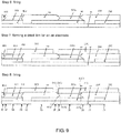
- the interconnector 303 and the solid electrolyte (104, 204, 304, 404) are formed by co-firing a first interconnector precursor formed on the surface of the fuel electrode (102, 202, 302, 402), a dried film of a solid electrolyte (104, 204, 304, 404) formed on the surface of the first interconnector precursor, and a second interconnector precursor formed on the surface of the first interconnector precursor and the dried film of the solid electrolyte (104, 204, 304, 404).
- first interconnector precursor, the second interconnector precursor, and the dried film of the solid electrolyte (104, 204, 304, 404) are mutually diffused by co-firing.
- first interconnector precursor and the second interconnector precursor have a mutually contacted portion and a mutually noncontacted portion formed by forming a dried film of the solid electrolyte (104, 204, 304, 404) in a portion of an area between the first interconnector precursor and the second interconnector precursor.
- a dried film of a solid electrolyte (204) in adjacent one power generation element, for example, a first power generation element 20, and/or a dried film of a solid electrolyte (304) in the other power generation element, for example, a second power generation element 30, are formed.
- elements are diffused between both the interconnector precursors in a portion where both the interconnector precursors are in contact with each other, while elements are not diffused between both the interconnector precursors in a portion where both the interconnector precursors are not in contact with each other.
- Sr is present in a large amount on the surface of the dried film of the solid electrolyte (104, 204, 304, 404), and, when the second interconnector precursor represented by the formula (2) which is highly reactive with the dried film of the solid electrolyte (104, 204, 304, 404) is formed, both the dried film of the solid electrolyte and the second interconnector precursor are reacted with each other during co-firing according to the mechanism of element diffusion described later to improve the adhesion between the solid electrolyte (104, 204, 304, 404) and the interconnector 303. As a result, gas sealing property between the solid electrolyte (104, 204, 304, 404) and the interconnector 303 can be improved.
- the co-firing temperature is preferably 1,250°C (inclusive) to 1,400°C (exclusive).
- elements contained in each of the first interconnector precursor, the second interconnector precursor and the dried film of the solid electrolyte (104, 204, 304, 404) are mutually diffused.
- the portion in the second interconnector precursor that is not in contact with the first interconnector precursor is formed of the perovskite oxide represented by the formula (2).
- formed of means that the main component of the portion in the second interconnector precursor that is not in contact with the first interconnector precursor is the perovskite oxide represented by the formula (2). That is, an embodiment where the portion in the second interconnector precursor that is not in contact with the first interconnector precursor contains other components, for example, diffusion elements described later is not excluded. In other words, preferably, the portion in the second interconnector precursor that is not in contact with the first interconnector precursor contains as a main component the perovskite represented by the formula (2).
- the main component means that, in the portion of the second interconnector precursor that is not in contact with the first interconnector precursor, the content of the perovskite oxide represented by the formula (2) is not less than 80% by mole, preferably not less than 90% by mole, more preferably not less than 95% by mole. Still more preferably, the portion in the second interconnector precursor that is not in contact with the first interconnector precursor consists of the perovskite oxide represented by the formula (2) only. This can allow the portion in the second interconnector precursor that is not in contact with the first interconnector precursor to be formed as an oxide ion insulating member 310. As a result, leakage of oxide ions can be suppressed, and the output of power generation of the power generation element can be improved.
- the oxide ion insulating member 310 thus formed is provided between the interconnector 303 and the solid electrolyte 204 in adjacent one power generation element, for example, first power generation element 20, and/or between the interconnector 303 and the solid electrolyte 304 in the other power generation element, for example, second power generation element 30.
- the mechanism of element dispersion by firing specifically the mechanism of element diffusion between the first and second interconnector precursors and mutual diffusion of elements between each of the interconnector precursors and the solid electrolyte (104, 204, 304, 404), are considered as follows.
- the present invention is not limited thereto.
- Firing in such a state that the first interconnector precursor is in contact with the second interconnector precursor can allow elements contained in the first interconnector precursor and the second interconnector precursor to be heat-diffused from a high concentration region towards a low concentration region using a concentration gradient as a driving force.
- Sr is diffused from the second interconnector precursor into the first interconnector precursor.
- La is diffused from the first interconnector precursor into the second interconnector precursor.
- Ti is diffused from the second interconnector precursor into the first interconnector precursor.
- a strongly adhered integral layer can be formed. That is, an interconnector 303 having excellent airtightness can be obtained.
- an interconnector 303 can be obtained that has a compositional gradient within a composition range shown in formula (1) in the thickness-wise direction. Further, when Fe and Nb are diffused from the first interconnector precursor into the second interconnector precursor, a lowering in electrical conductivity of the interconnector 303 by dissolution of Ni as a solid solution can be suppressed, contributing to improved oxide ion insulating property.
- the second interconnector precursor develops electrical conductivity using SrTiO 3 as a base and through replacement thereof with La. Further, the solid electrolyte develops oxide ion conductivity using LaGaO 3 as a base and through replacement thereof with Sr.
- La contained in the second interconnector precursor is diffused into the solid electrolyte (104, 204, 304, 404), and near-stable SrTiO 3 crystals can be obtained.
- Sr contained in the solid electrolyte (104, 204, 304, 404) is diffused into the second interconnector precursor, and near-stable LaGaO 3 crystals can be obtained. Since both SrTiO 3 and LaGaO 3 have oxide ion insulating properties, in the second interconnector and the solid electrolyte, the portion formed by firing in such a state that the second interconnector precursor is in contact with the solid electrolyte (104, 204, 304, 404) becomes insulative against oxide ions through element diffusion by firing.
- the first interconnector precursor develops electrical conductivity using SrTiO 3 as a base and through the replacement of Sr site with La and Ti site with Nb and Fe. Further, the solid electrolyte (104, 204, 304, 404) develops oxide ion conductivity using LaGaO 3 as a base and through the replacement of La site with Sr.
- the solid electrolyte 104, 204, 304, 404
- La contained in the first interconnector precursor is diffused into the solid electrolyte (104, 204, 304, 404) and near-stable SrTiO 3 crystals can be obtained.
- Sr contained in the solid electrolyte (104, 204, 304, 404) is diffused into the first interconnector precursor and near-stable LaGaO 3 crystals can be obtained.
- Fe and Nb are heat-diffused from the first interconnector precursor into the solid electrolyte (104, 204, 304, 404) using a concentration gradient as a driving force.
- the portion formed by firing in such a state that the first interconnector precursor is in contact with the solid electrolyte (104, 204, 304, 404) becomes insulative against oxide ions through element diffusion by firing.
- the lower limit of the electrical conductivity of the interconnector 303 is preferably 0.05 S/cm or more, more preferably 0.1 S/cm or more. The higher the electrical conductivity, the better the results. Thus, there is no upper limit of the electrical conductivity. Preferably, however, the electrical conductivity is not more than 0.16 S/cm. When the electrical conductivity of the interconnector is in such a range, the electrical conductivity of the interconnector 303 can be improved, and the power generation performance of the solid oxide fuel cell stack 210 can be improved.
- the upper limit of the porosity of the interconnector 303 is preferably 1% or less, more preferably 0.1% or less.
- the lower limit is preferably 0% or more.
- the thickness of the interconnector 303 is preferably 5 to 50 ⁇ m.
- the porosity can be measured by the following method.
- An SEM image is obtained by cutting out a specimen so as to include an interconnector from the solid oxide fuel cell stack and observing the interconnector with a scanning electron microscope (for example, S-4100 manufactured by Hitachi, Ltd.) under conditions of an accelerated voltage of 15 kV, a secondary electron image, and a magnification of 100 to 10000 times.
- the SEM image is evaluated by a software for image processing (for example, Winroofver 6.5.1 manufactured by MITANI CORPORATION). As a result, a histogram including a brightness as abscissa and an appearance frequency as ordinate is obtained.
- the porosity determined by the following method can be used as one index.
- Specimens are obtained by subjecting a raw material powder for the interconnector to uniaxial pressing under a load of 900 kgf/cm 2 and firing the pressed product at 1300°C for 2 hours under an atmospheric environment.
- the porosity is measured by an Archimedes method according to JIS R 1634.
- the electrical conductivity can be measured by the following method.
- a solid oxide fuel cell stack is prepared.
- a current collector on the fuel electrode side is formed by cladding a current collecting metal to an exposed area of the fuel electrode in adjacent one power generation element with a silver paste and conducting baking.
- a current collector on the air electrode side including the interconnector 303 is formed by cladding a current collecting metal to an exposed area of a fuel electrode in adjacent the other power generation element with a silver paste and conducting baking.
- a current collector on the interconnector-free air electrode side is formed by cladding a current collecting metal to an air electrode of adjacent one power generation element with a silver paste and conducting baking. Thereafter, the voltage between terminals is measured under the following power generation conditions by connecting a potential wire and a current wire to the fuel electrode in the adjacent one power generation element and to the fuel electrode in the adjacent other power generation element and connecting a potential wire to the air electrode.
- the voltage between terminals (V) connected to the fuel electrode in the one power generation element and the fuel electrode in the other power generation element and the voltage between terminals (V') connected to the fuel electrode in the one power generation element and the air electrode in the one power generation element are measured.
- the area of the interconnector and the air electrode is determined, for example, with a vernier caliper after peeling-off of the interconnector and the air electrode from the solid oxide fuel cell stack after the power generation test.
- the electrical conductivity determined by the following method can be used as one index.
- a specimen for the measurement of electrical conductivity is prepared by subjecting a raw material powder for the interconnector to uniaxial pressing under a load of 900 kgf/cm 2 and firing the pressed product at 1300°C for 2 hours under an atmospheric environment.
- the electrical conductivity of the specimen is measured by a direct current four-terminal method based on JIS (Japanese Industrial Standards) R 1650-2 under an atmospheric environment at 700°C.
- a horizontal-striped solid oxide fuel cell stack 210 includes 13 power generation elements connected in series on a support 201.
- Power generation elements 10, 20, 30, and 40 are four power generation elements continuously adjacent to each other.
- Fig. 1(B) illustrates four adjacent power generation elements 10, 20, 30, 40 in a horizontal-striped solid oxide fuel cell stack 210.
- the solid oxide fuel cell stack 210 in Fig. 1(B) is of a type in which the inner electrode is a fuel electrode 102, 202, 302, 402.
- the solid oxide fuel cell stack 210 includes a support 301, first/second fuel electrode, that is, fuel electrode layers 102a, 202a, 302a, 402a, and fuel electrode catalyst layers 102b, 202b, 302b, 402b, first/second solid electrolytes, that is, reaction inhibitory layers 104a, 204a, 304a, 404a, and solid electrolyte layers 104b, 204b, 304b, 404b, air electrodes 105b, 205b, 305b, 405b, current collecting layers 105a, 205a, 305a, 405a, and an interconnector 303.
- first/second means that the structure is a single-layer or two-layer structure and, in two layers, has a first layer and a second layer.
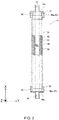
- Fig. 2 is a partial cross-sectional view of a vertical-striped solid oxide fuel cell unit constituting a vertical-striped solid oxide fuel cell stack that is one embodiment of the present invention.
- the vertical-striped solid oxide fuel cell unit 16 includes a fuel cell 84 and an inner electrode terminal 86 connected to an upper directional end and a lower directional end of the fuel cell 84.
- the fuel cell 84 is a vertically extended tubular structure and includes: a cylindrical porous support 91 with a fuel gas flow path 88 provided in its interior; and, an inner electrode layer 90 provided on a surface of the porous support 91, an outer electrode layer 92, and a solid electrolyte 94 provided between the inner electrode layer 90 and the outer electrode layer 92.
- the interconnector and the air electrode are connected to each other through a metal such as Ag or an electrically conductive ceramic.
- An upper part 90a of the inner electrode layer 90 includes an outer peripheral face 90b and an upper end face 90c exposed to the solid electrolyte 94 and the outer electrode layer 92.
- the inner electrode terminal 86 is connected to the outer peripheral face 90b of the inner electrode layer 90 through an electrically conductive sealing material 96 and is in directly contact with the upper end face 90c of the inner electrode layer 90, thereby being electrically connected to the inner electrode layer 90.
- a fuel gas flow path 98 in communication with the fuel gas flow path 88 in the inner electrode layer 90 is provided at the central portion of the inner electrode terminal 86.
- Fig. 3 is a perspective view of a vertical-striped solid oxide fuel cell stack as one embodiment of the present invention.
- the vertical-striped solid oxide fuel cell stack 14 includes 16 vertical-striped solid oxide fuel cell units 16.
- the lower end side and the upper end side of the vertical-striped solid oxide fuel cell unit 16 are supported by ceramic lower support plate 68 and upper support plate 100, respectively.
- Through-holes 68a and 100a through which the inner electrode terminal 86 can be penetrated are provided in these lower support plate 68 and upper support plate 100, respectively.
- a current collector 102 and an external terminal 104 are mounted in the vertical-striped solid oxide fuel cell unit 16.
- the current collector 102 is integrally formed by a fuel electrode connector 102a electrically connected to the inner electrode terminal 86 mounted on the inner electrode layer 90 as the fuel electrode, and an air electrode connector 102b electrically connected to the whole outer peripheral face of the outer electrode layer 92 as the air electrode.
- the air electrode connector 102b includes a vertical portion 102c vertically extended on the surface of the outer electrode layer 92, and a number of horizontal portion 102b horizontally extended from the vertical portion 102c along the surface of the outer electrode layer 92.
- the fuel electrode connector 102a is linearly extended from the vertical portion 102c of the air electrode connector 102b in an obliquely upper or lower direction towards the inner electrode terminal 86 located in the upper and lower directions of the fuel cell unit 16.
- An external terminal 104 is connected to the inner electrode terminal 86 on the upper end of a vertical-striped solid oxide fuel cell unit 16.
- An external terminal 104 is connected to the inner electrode terminal 86 on the lower end of a vertical-striped solid oxide fuel cell unit 16.
- the two vertical-striped solid oxide fuel cell units 16 are located at the ends (back side and front side at the left end in Fig. 3 ) of the vertical-striped solid oxide fuel cell stack 14.
- These external terminals 104 are connected to external terminals 104 (not shown) in the vertical-striped solid oxide fuel cell units 16 located at the ends of the adjacent vertical-striped solid oxide fuel cell stack 14, and, as described above, all of 16 vertical-striped solid oxide fuel cell units 16 are connected in series.
- Fig. 4 is a schematic view of illustrating one preferred embodiment of the solid oxide fuel cell stack 220 according to the present invention.
- the solid oxide fuel cell stack 220 includes a support 301 and four power generation elements (10, 20, 30, 40) provided on a surface of the support 301.
- the first power generation element 20 includes, as constituent members, a first fuel electrode 202, a first air electrode 205, and a first solid electrolyte 204 provided between the first fuel electrode 202 and the first air electrode 205.
- the first fuel electrode 202 is arranged between the support 301 and the first air electrode 205.
- the second power generation element 30 includes, as constituent members, a second fuel electrode 302, a second air electrode 305, and a second solid electrolyte 304 provided between the second fuel electrode 302 and the second air electrode 305.
- the second fuel electrode 302 is arranged between the support 301 and the second air electrode 305.
- the solid oxide fuel cell stack 220 further includes an interconnector 303 that electrically connects the first air electrode 205 in the first power generation element 20 to the second fuel electrode 302 in the second power generation element 30.
- the first power generation element 20 and the second power generation element 30 are connected in series through the interconnector 303.
- the first fuel electrode 202, the first solid electrolyte 204, and the first air electrode 205, or the second fuel electrode 302, the second solid electrolyte 304, and the second air electrode 305 are arranged in Z-axis direction.
- the first power generation element 20 includes, for example, a first area 21, a second area 22, a third area 23, and a sixth area 26.
- the first power generation element 20 further includes a fourth area 24 and a fifth area 25.
- the third area 23, the second area 22, the first area 21, and the sixth area 26 are continuously provided in that order and adjacent to each other in X-axis direction.
- first power generation element 20 further includes a fourth area 24 and a fifth area 25, the fifth area 25, the third area 23, the second area 22, the first area 21, the sixth area 26, and the fourth area 24 are provided in that order and adjacent to each other in X-axis direction.
- the second fuel electrode 302, the first solid electrolyte 204, and the first air electrode 205 are arranged in that order in Z-axis direction.
- the first solid electrolyte 204 and the first air electrode 205 are arranged in that order in Z-axis direction.
- the first fuel electrode 202, the first solid electrolyte 204, and the first air electrode 205 are arranged in that order in Z-axis direction.
- the second fuel electrode 302, the second solid electrolyte 304, and the first air electrode 205 are arranged in that order in Z-axis direction.
- the first fuel electrode 202 and the first solid electrolyte 204 are arranged in that order in Z-axis direction.
- the second fuel electrode 302, the interconnector 303a, and the first air electrode 205 are arranged in that order in Z-axis direction.
- the first area 21, the fourth area 24, and the sixth area 26 are formed of a constituent member for the first power generation element 20 and a constituent member for the second power generation element 30.
- the second area 22, the third area 23, and the fifth area 25 consists of only a constituent member for the first power generation element 20.
- the third area 23 includes all constituent members for the first power generation element 20.
- the first fuel electrode 202, the first solid electrolyte 204, and the first air electrode 205 are arranged in that order in Z-axis direction, and the third area 23 functions as a power generation unit in the first power generation element 20.
- the first power generation element 20 (first air electrode 205) and the second power generation element 30 (second fuel electrode 302) are connected in series through the interconnector 303.
- the thickness of the interconnector 303 refers to a length of the interconnector 303 along Z-axis in the sixth area 16, 26, 36. That is, the length between the fuel electrode, for example, second fuel electrode 302, and the air electrode, first air electrode 205, corresponds to the thickness of the interconnector 303.
- the second power generation element 30 also includes the first area 31 to the sixth area 36.
- Insulating portion and each portion thereof
- the solid oxide fuel cell stack 220 may further include an insulating member 310.
- the insulating member 310 is in contact with the interconnector 303.
- the insulating member 310 includes a first portion 310a and a second portion 310b.
- the insulating member 310 further includes a third portion 310c, a fourth portion 310d, and a fifth portion 310e.
- the insulating member 310 may further include a sixth portion 310f, a seventh portion 310g, an eighth portion 310h, a ninth portion 310i, and a tenth portion 310j.
- the first portion 310a is provided between the first solid electrolyte 204 and the first air electrode 205.
- the second portion 310b is provided between the first solid electrolyte 204 and the first air electrode 205.
- the second portion 310b is provided in contact with the interconnector 303.
- the whole area of the surface of the interconnector 303 is preferably covered with the first air electrode 205. This can enlarge the area of contact between the interconnector 303 and the first air electrode 205. As a result, the electrically conductive area of the interconnector 303 can be increased, contributing to enhanced electrical conductivity. Thus, the output of power generation of the power generation element can be improved.
- the insulating member 310 is described in more detail.
- the third portion 310c in the insulating member 310 is provided between the second solid electrolyte 304 and the first air electrode 205 in the fourth area 24.
- the whole area of the surface of the first portion 310a, the second portion 310b, and the third portion 310c in the insulating member 310 is covered with the first air electrode 205.
- the third portion 310c is provided in contact with the interconnector 303a. Leakage of oxide ions can be prevented by adopting such a construction that the air electrode 205 in one power generation element 20 is not in contact with the solid electrolyte 304 in the other power generation element 30. As a result, the formation of a counter cell can be suppressed. Further, the distance between the adjacent power generation elements can be reduced, and the resistance between the power generation elements can be reduced.
- the fifth portion 310e in the insulating member 310 is provided on the second solid electrolyte 304 and is provided adjacent to the third portion 310c in X-axis direction.
- the fourth portion 310d in the insulating member 310 is provided between the first solid electrolyte 204 and the first air electrode 205.
- the fourth portion 310d is provided adjacent to the fifth portion 310e in X-axis direction.
- the third area (13, 23, 33, 43) in the power generation element (10, 20, 30, 40) is an area that contributes to power generation. Therefore, an embodiment where the fourth portion 310d is not provided can be adopted from the viewpoint of power generation efficiency.
- Fig. 5 is a view of illustrating one preferred embodiment of the solid oxide fuel cell stack 220 according to the present invention.
- An oxide ion insulating portion (310a, 310b) is provided between a solid electrolyte 204 in one power generation elements and an interconnector 303, and the oxide ion insulating portion (310a, 310b) is in contact with the interconnector 303 and the solid electrolyte 204 in the one power generation elements.
- an oxide ion insulating portion 310c is provided between a solid electrolyte 304 in the other power generation element and a interconnector 303, and the oxide ion insulating portion 310c is in contact with the interconnector 303 and tfhe solid electrolyte 304 in the other power generation element.
- This can realize the suppression of leakage of oxide ions, and, as a result, the output of power generation in the power generation element can be improved.
- Fig. 5 an embodiment is illustrated where two oxide ion insulating portions are provided. However, it should be noted that an embodiment where any one of the oxide ion insulating portions is provided is also encompassed in the scope of the present invention.
- the solid oxide fuel cell stack 220 illustrated in Fig. 5 is described in more detail.
- the solid oxide fuel cell stack 220 includes three adjacent power generation elements 20, 30 and 40.
- An oxide ion insulating portion (310a, 310b) is provided between the solid electrolyte 204 in the first power generation element 20 and the interconnector 303, and the oxide ion insulating portion (310a, 310b) is in contact with the interconnector 303 and the solid electrolyte 204 in the first power generation element 20.
- an oxide ion insulating portion 310c is provided between the solid electrolyte 304 in the second power generation element 30 and the interconnector 303, and the oxide ion insulating portion 310c is in contact with the interconnector 303 and the solid electrolyte 304 in the second power generation element 30.
- an oxide ion insulating portion (310a, 310b) is provided between the solid electrolyte 304 in the second power generation element 30 and the interconnector 303, and the oxide ion insulating portion (310a, 310b) is in contact with the interconnector 303 and the solid electrolyte 304 in the second power generation element 20.
- an oxide ion insulating portion 310c is provided between the solid electrolyte 404 in the third power generation element 40 and the interconnector 303, and the oxide ion insulating portion 310c is in contact with the interconnector 303 and the solid electrolyte 404 in the third power generation element 40.
- Fig. 5 illustrates an embodiment where two oxide ion insulating portions (310a and 310b, and 310c) are provided between two adjacent power generation elements, for example, first power generation element 20 and second power generation element 30, and second power generation element 30 and third power generation element 40.
- any one of the power generation elements is provided is also encompassed in the scope of the present invention.
- the whole area of the surface of the interconnector 303 is covered with the air electrode 205 in the one power generation element.
- the area of contact between the interconnector 303 and the air electrode 205 can be enlarged.
- the electrically conductive area in the interconnector 303 can be enlarged, the electrical conductivity can be enhanced.
- the output of power generation in the power generation element can be improved.
- the whole area of the surface of the interconnector 303 is covered with the air electrode 205, preferably, a construction is adopted in which, as described below, the air electrode 205 in one power generation element 20 is not in contact with the solid electrolyte 304 in the other power generation element 30.
- an insulating portion 310c is further provided between the air electrode 205 in the one power generation element 20 and the solid electrolyte 304 in the other power generation element 30.
- two adjacent power generation elements (20, 30) further include a fourth area 24 in which a second fuel electrode 302, a second solid electrolyte 304, and a first air electrode 205 are arranged in that order in Z-axis direction, and, in the fourth area 24, the insulating member 310 further includes a third portion 310c provided between the second solid electrolyte 304 and the first air electrode 205.
- the fourth area 24 is continuously adjacent to a sixth area 26 in X-axis direction. That is, the whole area of the surface of the first portion 310a, the second portion 310b, and the third portion 310c in the insulating member 310 is covered with the first air electrode 205.
- the air electrode 205 in the first power generation element 20 can also be not in contact with the solid electrolyte 304 in the second power generation element 30, and, thus, leakage of oxide ions that occurs when the air electrode 205 is in contact with the solid electrolyte 304 can also be prevented.
- the formation of a counter cell can be suppressed. Further, the distance between adjacent power generation elements can be reduced, and the resistance between the power generation elements can be reduced.
- an insulating portion (310a, 310b) is provided between the solid electrolyte 204 in the first power generation element 20 and the air electrode 205 in the first power generation element 20, and an insulating portion 310c is provided between the air electrode 205 in the first power generation element 20 and the solid electrolyte 304 in the second power generation element 30, and both the insulating portion (310a, 310b) and the insulating portion 310c are in contact with the interconnector 303a.
- the insulating portion 310 is further described.
- the insulating member 310 in the solid oxide fuel cell stack 220 further includes an eighth portion 310h, in the fourth area 24 in the first power generation element 20, that is provided between the second fuel electrode 302 and the second solid electrolyte 304.
- an unfavorable phenomenon that a counter cell is formed through the occurrence of power generation in the fourth area 24 where the second fuel electrode 302, the second solid electrolyte 304, and the first air electrode 205 are arranged in that order in Z-axis direction in the first power generation element can be suppressed.
- the eighth portion 310h in the insulating portion is joined to the interconnector 303a and the solid electrolyte 304, and, thus, the gas sealing property of the interconnector 303 can be enhanced.
- the insulating portion 310 in the solid oxide fuel cell stack 220 further includes a sixth portion 310f, in the fifth area 35 in the second power generation element 30, that is provided between the second fuel electrode 302 and the second solid electrolyte 304.
- a sixth portion 310f in the fifth area 35 in the second power generation element 30, that is provided between the second fuel electrode 302 and the second solid electrolyte 304.
- an interconnector 303a, an eighth portion 310h, and a sixth portion 310f are arranged in that order and are adjacent to each other in X-axis direction. The provision of the sixth portion 310f in the insulating portion can further enhance the gas sealing property of the interconnector 303.
- the insulating member 310 in the solid oxide fuel cell stack 220 further includes a ninth portion 310i, in a part of the third area 33 in the second power generation element 30, that is provided between the second fuel electrode 302 and the second solid electrolyte 304.
- a sixth portion 310f and a ninth portion 310i are arranged in that order and are adjacent to each other in X-axis direction.
- the provision of the ninth portion 310i in the insulating portion can further enhance the gas sealing property of the interconnector 303a.
- the third area (13, 23, 33, 43) in the power generation element (10, 20, 30, 40) is an area that contributes to power generation. Therefore, an embodiment where the ninth portion 310i is not provided can be adopted from the viewpoint of power generation efficiency.
- the insulating member 310 in the solid oxide fuel cell stack 220 further includes a seventh portion 310g, in the first area 21 in the first power generation element 20, that is provided between the second fuel electrode 302 and the first solid electrolyte 204.
- the seventh portion 310g is disposed in contact with the interconnector 303a.
- the insulating member 310 in the solid oxide fuel cell stack 220 further includes a tenth portion 310j, in the second area 32 in the second power generation element, that is provided between the support 301 and the second solid electrolyte 304 in Z-axis direction and between the second solid electrolyte 304, and the third fuel electrode 402 and the seventh portion 310g in the insulating portion in X-axis direction. This can enhance the gas sealing property of the interconnector 303a.
- materials for the interconnector 303 that are insulative against oxide ions may be used instead of each of the above insulating portions.
- the solid oxide fuel cell stack according to the present invention may be manufactured by any method without particular limitation to particular method.
- the solid oxide fuel cell stack according to the present invention can be manufactured as follows. The manufacturing method is described by taking, as an example, a fuel electrode as an inner electrode and an air electrode as an outer electrode.
- the support can be prepared as follows.
- a solvent for example, water or alcohol
- dispersants, binders, defoamers, or pore forming agents or a combination thereof may be added as optional ingredient.
- sheet molding, press molding, and extrusion molding are used for molding of the green body.
- extrusion molding is preferably used.
- a support having a multi-layered structure is molded, in addition to multi-layer extrusion molding in which a plurality of layers are extruded at a time, a method in which the upper layer is formed by coating or printing may also be used.
- coating methods include slurry coating methods in which a raw material slurry is coated, tape casting methods, doctor blade methods, and transfer methods.
- printing methods include screen printing methods and ink jet printing methods.
- the prepared green body is molded, and the molded product is dried to obtain a support precursor.
- the support precursor is then calcined (800°C (inclusive) to 1100°C (exclusive)) to obtain a porous calcination product for the support and the calcination product for the support is solely fired to obtain a support.
- the calcination product for the support together with at least a fuel electrode and others, may be fired to obtain a support.
- the firing is preferably carried out at 1100°C (inclusive) to 1400°C (exclusive).
- the interconnector 303 can be prepared as follows.
- a raw material powder is prepared.
- the raw material powder can be prepared, for example, by a solid phase method. That is, powders of metal oxides as the raw material are weighed so as to provide a desired composition ratio. The powders are mixed in a solution, and the solvent is removed to obtain a powder. The powder is fired, for example, at 115°C, followed by grinding to prepare a raw material powder.
- a solvent for example, water or alcohol, and, if necessary, molding assistants such as dispersants and binders are added to the raw material powder to prepare a slurry or a paste.
- An interconnector can be obtained by coating the slurry or the paste, drying the slurry or the paste (80°C or more to 1100°C or less, preferably 300°C or more to 1100°C or less) to form a dried film and firing the film (1100°C (inclusive) to 1400°C (exclusive), preferably 1250°C (inclusive) to 1400°C (exclusive)).
- the coating may be carried out by the same method as described above. Alternatively, a method may be adopted in which each dried film is previously formed as a transfer sheet and the transfer film is applied to a lamination body.
- the fuel electrode (202, 302, 402), the solid electrolyte (204, 304, 404), and the air electrode (205, 305, 405) can be prepared as follows.
- a solvent for example, water or alcohol, and, if necessary, molding assistants such as dispersants and binders are added to the raw material powder to prepare a slurry or a paste.
- the fuel electrode (202, 302, 402), the solid electrolyte (204, 304, 404), and the air electrode (205, 305, 405) can be obtained by coating the slurry or the paste, drying the slurry or the paste (80°C or more to 1100°C or less, preferably 300°C or more to 1100°C or less) to form a dried film and firing the film (1100°C (inclusive) to 1400°C (exclusive), preferably 1250°C (inclusive) to 1400°C (exclusive)).
- the coating may be carried out by the same method as described above. Alternatively, a method may be adopted in which each dried film is previously formed as a transfer sheet and the transfer film is applied to a lamination body.
- firing is preferably carried out for each layer formation. That is, in this embodiment, the manufacturing method includes at least the steps of: forming a dried film for a fuel electrode (202, 302, 402) on a surface of a support 301 or a calcination product for the supportand then firing the dried film to form a fuel electrode (202, 302, 402); forming a dried film for an interconnector 303 and then firing the dried film to form an interconnector 303; forming a dried film for a solid electrolyte (204, 304, 404) and firing the dried film to form a solid electrolyte (204, 304, 404); and forming a dried film for an air electrode (205, 305, 405) and then firing the dried film to form an air electrode (205, 305, 405).
- a current collecting layer is formed after the formation of the air electrode 307.
- the interconnector 303 is formed by forming a first interconnector precursor 303-1 and a second interconnector precursor 303-2 and then co-firing the precursors (1250°C (inclusive) to 1400°C (exclusive)).
- the first interconnector precursor 303-1 and the second interconnector precursor 303-2 can be prepared as follows.
- a raw material powder is prepared.
- the raw material powder can be prepared, for example, by a solid phase method. That is, powders of metal oxides as the raw material are weighed so as to provide a desired composition ratio. The powders are mixed in a solution, and the solvent is removed to obtain a powder. The powder is fired, for example, at 1150°C, followed by grinding to prepare a raw material powder.
- a solvent for example, water or alcohol, and, if necessary, molding assistants such as dispersants and binders are added to the raw material powder to prepare a slurry or a paste.
- Each interconnector precursor can be obtained by coating the slurry or the paste, drying the slurry or the paste (80°C or more to 1100°C or less, preferably 300°C or more to 1100°C or less).
- the coating may be carried out by the same methods as described above.
- a method may be adopted in which each dried film is previously formed as a transfer sheet and the transfer film is applied to a lamination body.
- the interconnector 303 and the solid electrolyte (204, 304, 404) are formed by forming the first interconnector precursor 303-1, the second interconnector precursor 303-2, and a dried film for the solid electrolyte (204, 304, 404) and then co-firing (1250°C (inclusive) to 1400°C (exclusive)) the dried products.
- the interconnector 303 and the solid electrolyte (204, 304, 404) are formed by a manufacturing method including the steps of: forming a first interconnector precursor 303-1: forming a dried film for a solid electrolyte (204, 304, 404) on the surface of the first interconnector precursor 303-1; forming a second interconnector precursor 303-2 on the surface of the first interconnector precursor 303-1 and the dried film for the solid electrolyte (204, 304, 404); and co-firing (1250°C (inclusive) to 1400°C (exclusive)) the first interconnector precursor 303-1, the dried film for the solid electrolyte (204, 304, 404), and the second interconnector precursor 303-2.
- This manufacturing method allows elements contained in the interconnector precursor (303-1, 303-2) and elements contained in the solid electrolyte (204, 304, 404) to be mutually diffused during co-firing. That is, when elements contained in the interconnector precursor (303-1, 303-2) are the same as those contained in the solid electrolyte (204, 304, 404), the elements are mutually diffused. Such elements include strontium and lanthanum and the like. This can improve adhesion between the interconnector and the solid electrolyte. Further, in the manufacturing method according to the present invention, as illustrated in Fig.
- a dried film for the solid electrolyte (204, 304) is formed in a part of the area between the first interconnector precursor 303-1 and the second interconnector precursor 303-2, so that the first interconnector precursor 303-1 and the second interconnector precursor 303-2 have a mutually contacted portion and a mutually non-contacted portion. That is, in the first interconnector precursor 303-1 and the second interconnector precursor 303-2, a dried film for the first solid electrolyte 204 and/or a dried film for the second solid electrolyte 304 are formed in a part of the area between the first interconnector precursor 303-1 and the second interconnector precursor 303-2.
- elements are mutually diffused in a portion where the interconnector precursors are in contact with each other (a dotted line portion in Fig. 6 described later), while elements are not mutually diffused in a portion where the interconnector precursors are not in contact with each other (303b, 303g, 303c, 303e, 303h, 303f, and 303i).
- element diffusion occurs between each of the precursors and the dried film for the solid electrolyte.
- the gas sealing property of the interconnector 303 can be further improved.
- the manufacturing method includes the steps of: preparing a support 301 (step 1); forming a dried film for a fuel electrode (202, 302, 402) (step 2); forming a first interconnector precursor 303-1 (step 3); forming a dried film for a solid electrolyte (204, 304, 404) (step 4); forming a second interconnector precursor 303-2 (step 5); then co-firing (1250°C (inclusive) to 1400°C (exclusive)) a laminate composed of the support 301, the dried film for the fuel electrode (202, 302, 402), the first interconnector precursor 303-1, the solid electrolyte (204, 304, 404), and the second interconnector precursor 303-2 (step 6); then forming a dried film for an air electrode (205, 305, 405) (step 7); and firing (1100°C (inclusive) to 1400°C (exclusive), preferably 1250°C (inclusive) to 1400°C (
- the laminate composed of the above is fired at a time, that is, co-fired.
- the firing is carried out under an oxidizing atmosphere so that the solid electrolyte (204, 304, 404) and the first and the second interconnector precursor (303-1 and 303-2) are not denatured, for example, due to diffusion of doapants. More preferably, firing is carried out under an atmosphere having an oxygen concentration of 20% by mass or more to 30% by mass or less using a mixed gas composed of air and oxygen.
- At least the first interconnector precursor 303-1, the dried film for the solid electrolyte (204, 304, 404), and the second interconnector precursor 303-2 are co-fired (1250°C (inclusive) to 1400°C (exclusive)).
- the second interconnector precursor 303-2 formed of SLT having a high Sr content and having a high reactivity with LSGM is formed on the surface of the dried film for the solid electrolyte (204, 304, 404) (for example, LSGM).
- the second interconnector precursor 303-2 and the dried film for the solid electrolyte (204, 304, 404) are reacted with each other through element diffusion occurred between them. Accordingly, adhesion between them are improved. As a result, gas sealing property between the solid electrolyte (204, 304, 404) and the interconnector 303 can be improved.
- the firing is carried out after each formation of dried films for individual member other than the first interconnector precursor 303-1, the dried film for the solid electrolyte (204, 304, 404), and the second interconnector precursor 303-2. That is, in this embodiment, the manufacturing method includes at least the steps of:
- a raw material powder of a high-purity forsterite (Mg 2 SiO 4 containing 0.05% by mass of CaO) was regulated to a mean particle diameter of 0.7 ⁇ m.
- 100 parts by weight of this powder 20 parts by weight of a solvent (water), 8 parts by weight of a binder (methylcellulose), 0.5 part by weight of a lubricant, and 15 parts by weight of a pore forming agent (acrylic resin particles having a mean particle diameter of 5 ⁇ m) were mixed in a rapid mixer, the mixture was kneaded in a kneader, the kneaded product was deaerated with a vacuum pug mill to prepare a green body for extrusion molding
- the mean particle diameter was measured according to JIS R1629 and expressed in terms of 50% diameter (the same shall apply hereinafter).
- a NiO powder and a 10YSZ (10 mol% Y 2 O 3 -90 mol% ZrO 2 ) power were mixed together by wet mixing at a weight ratio of 65 : 35 to obtain a dry powder.
- the dry powder thus obtained was regulated to a mean particle diameter of 0.7 ⁇ m.
- 150 parts by weight of this powder and 100 parts by weight of a solvent (carbitol) were mixed with 6 parts by weight of a binder (a soluble polymer), 2 parts by weight of a dispersant (a nonionic surfactant), and 2 parts by weight of an defoamer (organic polymeric substance-based). The mixture was thoroughly stirred to prepare a slurry.
- a mixture of a NiO powder and a GDC10 (10 mol% GdO1.5-90 mol% CeO2) powder was prepared by a coprecipitation method and was heat-treated to obtain a powder for a fuel electrode catalyst layer.
- the mixing ratio between the NiO powder and the GDC10 powder was 50/50 in terms of weight ratio.
- the mean particle diameter of the powder for the fuel electrode catalyst layer was regulated to a mean particle diameter of 0.5 ⁇ m.
- 100 parts by weight of this powder was mixed with 100 parts by weight of a solvent (carbitol), 5 parts by weight of a binder (a soluble polymeric substance), 2 parts by weight of a dispersant (nonionic surfactant), and 2 parts by weight of an defoamer (an organic polymeric substance). The mixture was thoroughly stirred to prepare a slurry.
- a powder of cerium-based composite oxide LDC40 (40 mol% LaO1.5-60 mol% CeO2) was used as a material for a reaction inhibitory layer. 0.04 part by weight of a Ga 2 O 3 powder was mixed into the material powder as a sintering aid. Further, 100 parts by weight of a solvent (carbitol), 4 parts by weight of a binder (a soluble polymeric substance), 1 part by weight of a dispersant (a nonionic surfactant), and 1 part by weight of an defoamer (a organic polymeric substance) were mixed thereinto, and the mixture was thoroughly stirred to prepare a slurry.
- a solvent carbbitol
- a binder a soluble polymeric substance
- a dispersant a nonionic surfactant
- an defoamer a organic polymeric substance
- An LSGM powder having a composition of La 0.9 Sr 0.1 Ga 0.8 Mg 0.2 O 3 was used as a material for a solid electrolyte. 50 parts by weight of this LSGM powder was mixed with 100 parts by weight of a solvent (carbitol), 4 parts by weight of a binder (a soluble polymeric substance), 1 part by weight of a dispersant (a nonionic surfactant), and 1 part by weight of an defoamer (an organic polymeric substance). The mixture was thoroughly stirred to prepare a slurry.
- a solvent carbbitol
- a binder a soluble polymeric substance
- a dispersant a nonionic surfactant
- an defoamer an organic polymeric substance
- a powder having a composition of La 0.6 Sr 0.4 CO 0.2 Fe 0.8 O 3 was used as a material for an air electrode. 40 parts by weight of this powder was mixed with 100 parts by weight of a solvent (carbitol), 2 parts by weight of a binder (a soluble polymeric substance), 1 part by weight of a dispersant (a nonionic surfactant), and 1 part by weight of an defoamer (an organic polymeric substance), and the mixture was thoroughly stirred to prepare a slurry.
- a solvent carbbitol
- a binder a soluble polymeric substance
- a dispersant a nonionic surfactant
- an defoamer an organic polymeric substance
- a raw material powder for a first interconnector precursor was prepared by a solid phase method. Metal oxide powders as raw materials were weighed so that strontium, lanthanum, titanium, niobium, and iron were present at a composition ratio of a perovskite oxide represented by Sr 0.37 La 0.52 Ti 0.50 Nb 0.10 Fe 0.40 O 3- ⁇ and were mixed together in a solution. Thereafter, the solvent was removed to give a powder that was then fired at 1050°C and ground to prepare a raw material powder for a first interconnector precursor.
- a raw material powder for a first interconnector precursor the raw material powder having a composition of Sr 0.37 La 0.52 Ti 0.50 Nb 0.10 Fe 0.40 O 3- ⁇ , was used as a material for a first interconnector precursor.
- 40 parts by weight of this powder was mixed with 100 parts by weight of a solvent (carbitol), 4 parts by weight of a binder (a soluble polymeric substance), 1 part by weight of a dispersant (a nonionic surfactant), and 1 part by weight of an defoamer (an organic polymeric substance). The mixture was thoroughly stirred to prepare a slurry.
- a raw material powder for a second interconnector precursor was prepared by a solid phase method. Metal oxide powders as raw materials were weighed so that strontium, lanthanum, and titanium were present at a composition ratio of a perovskite oxide represented by Sr 0.90 La 0.04 TiO 3- ⁇ and were mixed together in a solution. Thereafter, the solvent was removed to give a powder that was then fired at 1050°C and ground to prepare a raw material powder for a second interconnector precursor.
- a raw material powder for a second interconnector precursor the raw material powder having a composition of Sr 0.90 La 0.04 TiO 3- ⁇ , was used as a material for a second interconnector precursor.
- 40 parts by weight of this powder was mixed with 100 parts by weight of a solvent (carbitol), 4 parts by weight of a binder (a soluble polymeric substance), 1 part by weight of a dispersant (a nonionic surfactant), and 1 part by weight of an defoamer (an organic polymeric substance). The mixture was thoroughly stirred to prepare a slurry.
- a solid oxide fuel cell stack was prepared by the following method using the green body and each of the slurries prepared above.
- a cylindrical molded body was prepared from a green body A for a porous support by extrusion molding method. After drying at room temperature, the molded body was heat-treated at 1100°C for 2 hours to prepare a calcined body for a support.
- a fuel electrode layer, a fuel electrode catalyst layer, a first interconnector precursor, a reaction inhibitory layer, a solid electrolyte layer, and a second interconnector precursor were formed in that order on a surface of the support by a slurry coating method and were dried to obtain a laminated molded body including dried layers stacked.
- the laminated molded body was co-fired at 1300°C for 2 hours. During the firing, it is considered that mutual diffusion of elements occurs between the first and the second interconnector precursors and between the first and the second interconnector precursors and the solid electrolyte.
- an air electrode was molded on the surface of the solid electrolyte, and then fired at 1100°C for 2 hours to prepare a solid oxide fuel cell stack.
- the support had a dimension after co-firing of 10 mm in outer diameter and 1 mm in wall thickness.
- the thickness of the fuel electrode layer was 100 ⁇ m
- the thickness of the fuel electrode catalyst layer was 10 ⁇ m
- the thickness of the reaction inhibitory layer was 10 ⁇ m
- the thickness of the solid electrolyte layer was 30 ⁇ m
- the thickness of the interconnector was 15 ⁇ m
- the thickness of the air electrode was 20 ⁇ m.
- the outer diameter of the support was measured with a micrometer in a place where no layer was formed.
- Fig. 6 is a SEM image of a laminated structure formed, as viewed from below, a second fuel electrode 302 in a second power generation element 30, an interconnector 303, and a first air electrode 205 in a first power generation element 20 in that order.
- the upper side of the dotted line is a portion derived from a second interconnector precursor 303-2, and the lower side of the dotted line is a portion derived from a first interconnector precursor 303-1.
- a solid oxide fuel cell stack was obtained in the same manner as in Example 1, except that the composition of the first interconnector precursor and the composition of the second interconnector precursor were those shown in Table 1.
- the following evaluations were carried out. The results are shown in Table 1.
- a solid oxide fuel cell stack was obtained in the same manner as in Example 1, except that the first interconnector precursor was not provided and the composition of the second interconnector precursor was Sr 0.55 La 0.30 TiO 3- ⁇ .
- the following evaluations were carried out. The results are shown in Table 1.
- a solid oxide fuel cell stack was obtained in the same manner as in Example 1, except that the composition of the first interconnector precursor was Sr 0.40 La 0.55 Ti 0.50 Fe 0.50 O 3- ⁇ .
- the following evaluations were carried out. The results are shown in Table 1.
- the composition of the interconnector was identified by the following method.
- the interconnector was cut out from the prepared solid oxide fuel cell stack, followed by fabrication of the pieces into thin films having a thickness of 100 nm to 200 nm by FIB-SEM. Elemental mapping was obtained by evaluating the thin films by STEM-EDX.
- the composition ratio and the proportion of the perovskite oxide contained in the interconnector were determined by quantitatively analyzing the elemental mapping by a thin film approximation method. The results are shown in Table 1. As a result, it was confirmed that main components of the composition of the interconnector were the same as those of the composition of the raw material powder.
- a power generation test was carried out using the solid oxide fuel cell stack thus obtained.
- a current collector on the fuel electrode side was formed by cladding a current collecting metal to an exposed area of the fuel electrode with a silver paste.
- a current collector on the air electrode side was formed by cladding a current collecting metal to an exposed area of an adjacent fuel electrode with a silver paste.
- the amount of hydrogen used in the power generation was determined by the formula; amount of current (C/s) x 60 (s) x 22.4 (L/mol) ⁇ Faraday constant (C/mol) x 1/2 (valence) x number of power generation elements.
- the voltage between terminals was measured under the following power generation conditions by connecting a potential wire and a current wire to the fuel electrode in one of the adjacent power generation elements and to the fuel electrode in the adjacent other power generation element. The results are shown in Table 1.
Landscapes
- Chemical & Material Sciences (AREA)
- Engineering & Computer Science (AREA)
- Manufacturing & Machinery (AREA)
- Chemical Kinetics & Catalysis (AREA)
- General Chemical & Material Sciences (AREA)
- Electrochemistry (AREA)
- Sustainable Development (AREA)
- Sustainable Energy (AREA)
- Life Sciences & Earth Sciences (AREA)
- Materials Engineering (AREA)
- Ceramic Engineering (AREA)
- Composite Materials (AREA)
- Fuel Cell (AREA)
Claims (12)
- Ein Festoxid-Brennstoffzellenstapel, umfassend:eine Vielzahl von Stromerzeugungselementen, von denen jedes in dieser Reihenfolge eine Brennstoffelektrode, einen Feststoffelektrolyten und eine Luftelektrode gestapelt umfasst; undeinen Interkonnektor, der die Luftelektrode in einem der benachbarten Stromerzeugungselemente in der Vielzahl der Stromerzeugungselemente mit der Brennstoffelektrode in dem anderen Stromerzeugungselement elektrisch verbindet, wobei die Vielzahl von Stromerzeugungselementen in Reihe miteinander verbunden sind, dadurch gekennzeichnet, dass
der Interkonnektor aus einem Perowskit-Oxid besteht, das durch die folgende Formel (1) dargestellt wird:
SraLabTi1-c-dNbcFedO3-δ Formel (1)
wobei a, b, c und d eine positive reelle Zahl sind, die die Bedingung 0,1 ≤ a ≤ 0,8, 0,1 ≤ b ≤ 0,8, 0,05 ≤ c ≤ 0,2 und 0,2 ≤ d ≤ 0,5 erfüllt, und wobei der Sauerstoffgehalt (3-δ) nicht mehr als 3,00 beträgt, und
der Gehalt des durch die Formel (1) dargestellten Perowskit-Oxids im Interkonnektor nicht weniger als 80 Mol.-% beträgt. - Der Festoxid-Brennstoffzellenstapel gemäß Anspruch 1, wobei der Interkonnektor einen Gradienten hinsichtlich der Zusammensetzung innerhalb eines in der Formel (1) dargestellten Bereiches der Zusammensetzung in Richtung der Dicke aufweist.
- Der Festoxid-Brennstoffzellenstapel gemäß Anspruch 1 oder 2, der einen Oxidionen-Isolierabschnitt zwischen dem Interkonnektor und dem Feststoffelektrolyten in einem Stromerzeugungselement und/oder zwischen dem Interkonnektor und dem Feststoffelektrolyten in dem anderen Stromerzeugungselement umfasst, und der Oxidionen-Isolierabschnitt in Kontakt mit dem Interkonnektor und dem Feststofffelektrolyten in dem einen Stromerzeugungselement und/oder dem Feststoffelektrolyten in dem anderen Stromerzeugungselement steht.
- Der Festoxid-Brennstoffzellenstapel gemäß Anspruch 3, wobei der Oxidionen-Isolierabschnitt die folgende Formel (2) umfasst:
SrxLayTiO3-δ Gleichung (2)
wobei x und y eine positive Zahl sind, die die Bedingung 0,8 ≤ x + y ≤ 1,0 und 0,01 < y ≤ 0,1 erfüllt, und δ ein Wert ist, der erforderlich ist, um den neutralen Zustand der elektrischen Ladung zu erreichen. - Der Festoxid-Brennstoffzellenstapel gemäß irgendeinem der Ansprüche 1 bis 4, wobei der Feststoffelektrolyt aus einem mit Sr und Mg dotierten Lanthan-Gallat-basierten Oxid gebildet ist.
- Der Festoxid-Brennstoffzellenstapel gemäß irgendeinem der Ansprüche 1 bis 5, wobei der Interkonnektor durch gleichzeitiges Brennen der Folgenden gebildet wird
einer Vorstufe eines ersten Interkonnektors, die auf einer Oberfläche der Brennstoffelektrode ausgebildet wird und durch die folgende Formel (1') dargestellt wird:
SraLabTi1-c-dNbcFedO3-δ Formel (1'),
wobei a, b, c und d eine positive reelle Zahl sind, die die Bedingung 0,1 ≤ a ≤ 0,8, 0,1 ≤ b ≤ 0,8, 0,1 ≤ c ≤ 0,3 und 0,3 ≤ d ≤ 0,6 erfüllt, und der Sauerstoffgehalt (3-δ) nicht mehr als 3,00 beträgt, und
einer Vorstufe eines zweiten Interkonnektors, die auf einer Oberfläche der Vorstufe des ersten Interkonnektors gebildet wird und durch die folgende Formel (2) dargestellt wird:
SrxLayTiO3-δ Formel (2),
wobei x und y eine positive Zahl sind, die die Bedingung 0,8 ≤ x + y ≤ 1,0 und 0,01 < y ≤ 0,1 erfüllt und δ ein Wert ist, der erforderlich ist, um den neutralen Zustand der elektrischen Ladung zu erreichen. - Der Festoxid-Brennstoffzellenstapel gemäß irgendeinem der Ansprüche 1 bis 6, wobei der Interkonnektor und der Feststoffelektrolyt durch gleichzeitiges Brennen der Folgenden gebildet wird
der Vorstufe des ersten Interkonnektors, die auf der Oberfläche der Brennstoffelektrode ausgebildet wird,
wobei ein getrockneter Film aus einem Feststoffelektrolyten auf der Oberfläche der Vorstufe des ersten Interkonnektors gebildet wird, und
der Vorstufe des zweiten Interkonnektors, die auf der Vorstufe des ersten Interkonnektors und dem getrockneten Film des Feststoffelektrolyten ausgebildet wird,
wobei der getrocknete Film des Feststoffelektrolyten in dem einen Stromerzeugungselement und/oder der getrocknete Film des Feststoffelektrolyten in dem anderen Stromerzeugungselement in einem Teil einer Fläche zwischen der Vorstufe des ersten Interkonnektors und der Vorstufe des zweiten Interkonnektors ausgebildet werden, so dass die Vorstufe des ersten Interkonnektors und die Vorstufe des zweiten Interkonnektors teilweise in Kontakt miteinander stehen oder nicht. - Der Festoxid-Brennstoffzellenstapel gemäß Anspruch 6 oder 7, wobei in der Vorstufe des zweiten Interkonnektors der Bereich, der nicht mit der Vorstufe des ersten Interkonnektors in Kontakt steht, aus der Formel (2) gebildet ist.
- Ein Verfahren zur Herstellung eines Festoxid-Brennstoffzellenstapels, umfassend:eine Vielzahl von Stromerzeugungselementen, von denen jedes in dieser Reihenfolge eine Brennstoffelektrode, einen Feststoffelektrolyten und eine Luftelektrode gestapelt umfasst; undeinen Interkonnektor, der die Luftelektrode in einem der benachbarten Stromerzeugungselemente in der Vielzahl der Stromerzeugungselemente mit der Brennstoffelektrode in dem anderen Stromerzeugungselement elektrisch verbindet, wobei die Vielzahl von Stromerzeugungselementen in Reihe miteinander verbunden werden,wobei das Verfahren die folgenden Schritte umfasst:Bilden der Brennstoffelektrode;Bilden des Interkonnektors;Bilden des Feststoffelektrolyten; undBilden der Luftelektrode,dadurch gekennzeichnet, dassder Interkonnektor aus einem Perowskit-Oxid besteht, das durch die folgende Formel (1) dargestellt wird:
SraLabTi1-c-dNbcFedO3-δ Formel (1)
wobei a, b, c und d eine positive reelle Zahl sind, die die Bedingung 0,1 ≤ a ≤ 0,8, 0,1 ≤ b ≤ 0,8, 0,05 ≤ c ≤ 0,2 und 0,2 ≤ d ≤ 0,5 erfüllt, und dass der Sauerstoffgehalt (3-δ) nicht mehr als 3,00 beträgt, undder Gehalt des durch die Formel (1) dargestellten Perowskit-Oxids im Interkonnektor nicht weniger als 80 Mol.-% beträgt. - Das Verfahren zur Herstellung eines Festoxid-Brennstoffzellenstapels gemäß Anspruch 9, umfassend die Schritte:Bilden einer Vorstufe des ersten Interkonnektors mit der folgenden Formel (1'):
SraLabTi1-c-dNbcFedO3-δ Formel (1')
wobei a, b, c und d eine positive reelle Zahl sind, die die Bedingung 0,1 ≤ a ≤ 0,8, 0,1 ≤ b ≤ 0,8, 0,1 ≤ c ≤ 0,3 und 0,3 ≤ d ≤ 0,6 erfüllt, und der Sauerstoffgehalt (3-δ) nicht mehr als 3.00 beträgt,
auf der Oberfläche der Brennstoffelektrode,Bilden einer Vorstufe des zweiten Interkonnektors mit der folgenden Formel (2):
SrxLayTiO3-δ Formel (2)
wobei x und y eine positive Zahl sind, die die Bedingung 0,8 ≤ x + y ≤ 1,0 und 0,01 < y ≤ 0,1 erfüllen, und δ ein Wert ist, der erforderlich ist, um den neutralen Zustand der elektrischen Ladung zu erreichen,
auf der Oberfläche der Vorstufe des ersten Interkonnektors, undBilden des Interkonnektors durch gleichzeitiges Brennen der Vorstufe des ersten Interkonnektors und der Vorstufe des zweiten Interkonnektors. - Das Verfahren zur Herstellung eines Festoxid-Brennstoffzellenstapels gemäß Anspruch 10, umfassend die Schritte:Bilden eines getrockneten Films des Feststoffelektrolyten auf der Oberfläche der Vorstufe des ersten Interkonnektors;Bilden der Vorstufe des zweiten Interkonnektors auf der Oberfläche der Vorstufe des ersten Interkonnektors und des getrockneten Films des Feststoffelektrolyten; undBilden des Interkonnektors und des Feststoffelektrolyten durch gleichzeitiges Brennen der Vorstufe des ersten Interkonnektors, des getrockneten Films des Feststoffelektrolyten und der Vorstufe des zweiten Interkonnektors.
- Das Verfahren zur Herstellung eines Festoxid-Brennstoffzellenstapels gemäß Anspruch 11, wobei der getrocknete Film des Feststoffelektrolyten in einem Stromerzeugungselement und/oder der getrocknete Film des Feststoffelektrolyten in dem anderen Stromerzeugungselement in einem Teil einer Fläche zwischen der Vorstufe des ersten Interkonnektors und der Vorstufe des zweiten Interkonnektors ausgebildet werden, so dass die Vorstufe des ersten Interkonnektors und die Vorstufe des zweiten Interkonnektors teilweise miteinander in Kontakt stehen oder nicht.
Applications Claiming Priority (2)
| Application Number | Priority Date | Filing Date | Title |
|---|---|---|---|
| JP2014202411 | 2014-09-30 | ||
| JP2015074375A JP6712119B2 (ja) | 2014-09-30 | 2015-03-31 | 固体酸化物形燃料電池セルスタック |
Publications (2)
| Publication Number | Publication Date |
|---|---|
| EP3002811A1 EP3002811A1 (de) | 2016-04-06 |
| EP3002811B1 true EP3002811B1 (de) | 2017-06-28 |
Family
ID=54703712
Family Applications (1)
| Application Number | Title | Priority Date | Filing Date |
|---|---|---|---|
| EP15187535.8A Not-in-force EP3002811B1 (de) | 2014-09-30 | 2015-09-30 | Festoxidbrennstoffzellenstapel |
Country Status (3)
| Country | Link |
|---|---|
| US (1) | US20160093910A1 (de) |
| EP (1) | EP3002811B1 (de) |
| CN (1) | CN105470548A (de) |
Families Citing this family (2)
| Publication number | Priority date | Publication date | Assignee | Title |
|---|---|---|---|---|
| JP7021787B2 (ja) * | 2017-02-28 | 2022-02-17 | 国立研究開発法人産業技術総合研究所 | プロトン伝導性電解質 |
| CN106910926A (zh) * | 2017-04-07 | 2017-06-30 | 桂林理工大学 | 一种固体电解质材料及其制备方法 |
Family Cites Families (6)
| Publication number | Priority date | Publication date | Assignee | Title |
|---|---|---|---|---|
| JP5364393B2 (ja) * | 2009-02-12 | 2013-12-11 | 株式会社ノリタケカンパニーリミテド | 固体酸化物形燃料電池用インターコネクタとその利用 |
| JP5313726B2 (ja) | 2009-03-10 | 2013-10-09 | 株式会社ノリタケカンパニーリミテド | 固体酸化物形燃料電池および該電池用インターコネクタ |
| KR101227772B1 (ko) * | 2011-07-11 | 2013-01-29 | 한전케이피에스 주식회사 | 밀폐형 스프링 행거의 건전성 검사 장비 |
| JP5748593B2 (ja) | 2011-07-26 | 2015-07-15 | 日本碍子株式会社 | 電気化学セル |
| KR101405477B1 (ko) * | 2011-12-29 | 2014-06-19 | 재단법인 포항산업과학연구원 | 금속지지체형 고체산화물 연료전지용 셀의 제조방법 및 금속지지체형 고체산화물 연료전지용 셀 |
| CA2895125A1 (en) * | 2012-12-19 | 2014-06-26 | Zhien LIU | Fuel cell system with interconnect |
-
2015
- 2015-09-29 US US14/869,772 patent/US20160093910A1/en not_active Abandoned
- 2015-09-30 CN CN201510642034.5A patent/CN105470548A/zh active Pending
- 2015-09-30 EP EP15187535.8A patent/EP3002811B1/de not_active Not-in-force
Also Published As
| Publication number | Publication date |
|---|---|
| EP3002811A1 (de) | 2016-04-06 |
| US20160093910A1 (en) | 2016-03-31 |
| CN105470548A (zh) | 2016-04-06 |
Similar Documents
| Publication | Publication Date | Title |
|---|---|---|
| KR101953959B1 (ko) | 고체 산화물형 연료 전지 셀, 그 제조 방법, 연료 전지 셀 스택, 및 고체 산화물형 연료 전지 | |
| EP2495791B1 (de) | Brennstoffzelle, brennstoffzellenstapel, brennstoffzellenmodul und brennstoffzellenvorrichtung | |
| JP5160131B2 (ja) | 電解質・電極接合体及びその製造方法 | |
| EP2461405A1 (de) | Festoxid-brennstoffzelle | |
| KR20200019623A (ko) | 고체 전해질 부재, 고체 산화물형 연료 전지, 수 전해 장치, 수소 펌프 및 고체 전해질 부재의 제조 방법 | |
| EP3002813B1 (de) | Solild oxide fuel stack | |
| EP2936597B1 (de) | Pulvergemisch für schicht in einer festoxidbrennstoffzelle | |
| EP2854210A1 (de) | Festoxid-Brennstoffzellenstapel | |
| EP3809505B1 (de) | Zelle, zellenstapelvorrichtung, modul und modulspeichervorrichtung | |
| EP3002810B1 (de) | Festoxidbrennstoffzelle | |
| EP3002811B1 (de) | Festoxidbrennstoffzellenstapel | |
| JP4828104B2 (ja) | 燃料電池セル | |
| EP3002812B1 (de) | Festoxidbrennstoffzellenstapel | |
| EP2772473B1 (de) | Keramiksinterpressling, hochtemperaturelement und elektrochemisches element | |
| JP6654765B2 (ja) | 固体酸化物形燃料電池セルスタック | |
| JP5288686B2 (ja) | 燃料電池用導電性焼結体及び燃料電池セル、燃料電池 | |
| JP6712119B2 (ja) | 固体酸化物形燃料電池セルスタック | |
| JP6524756B2 (ja) | 固体酸化物形燃料電池セルスタック | |
| JP6654764B2 (ja) | 固体酸化物形燃料電池セルスタック | |
| JP7585822B2 (ja) | 固体酸化物形燃料電池 | |
| JP6712118B2 (ja) | 固体酸化物形燃料電池セルスタック | |
| JP6654766B2 (ja) | 固体酸化物形燃料電池セルスタック |
Legal Events
| Date | Code | Title | Description |
|---|---|---|---|
| PUAI | Public reference made under article 153(3) epc to a published international application that has entered the european phase |
Free format text: ORIGINAL CODE: 0009012 |
|
| 17P | Request for examination filed |
Effective date: 20150930 |
|
| AK | Designated contracting states |
Kind code of ref document: A1 Designated state(s): AL AT BE BG CH CY CZ DE DK EE ES FI FR GB GR HR HU IE IS IT LI LT LU LV MC MK MT NL NO PL PT RO RS SE SI SK SM TR |
|
| AX | Request for extension of the european patent |
Extension state: BA ME |
|
| RBV | Designated contracting states (corrected) |
Designated state(s): AL AT BE BG CH CY CZ DE DK EE ES FI FR GB GR HR HU IE IS IT LI LT LU LV MC MK MT NL NO PL PT RO RS SE SI SK SM TR |
|
| REG | Reference to a national code |
Ref country code: DE Ref legal event code: R079 Ref document number: 602015003315 Country of ref document: DE Free format text: PREVIOUS MAIN CLASS: H01M0008120000 Ipc: H01M0008124600 |
|
| RIC1 | Information provided on ipc code assigned before grant |
Ipc: H01M 8/1246 20160101AFI20161220BHEP Ipc: H01M 8/124 20160101ALN20161220BHEP Ipc: H01M 8/0226 20160101ALI20161220BHEP Ipc: H01M 8/2425 20160101ALI20161220BHEP Ipc: H01M 8/0217 20160101ALI20161220BHEP |
|
| GRAP | Despatch of communication of intention to grant a patent |
Free format text: ORIGINAL CODE: EPIDOSNIGR1 |
|
| INTG | Intention to grant announced |
Effective date: 20170127 |
|
| GRAS | Grant fee paid |
Free format text: ORIGINAL CODE: EPIDOSNIGR3 |
|
| GRAA | (expected) grant |
Free format text: ORIGINAL CODE: 0009210 |
|
| AK | Designated contracting states |
Kind code of ref document: B1 Designated state(s): AL AT BE BG CH CY CZ DE DK EE ES FI FR GB GR HR HU IE IS IT LI LT LU LV MC MK MT NL NO PL PT RO RS SE SI SK SM TR |
|
| REG | Reference to a national code |
Ref country code: GB Ref legal event code: FG4D |
|
| REG | Reference to a national code |
Ref country code: CH Ref legal event code: EP |
|
| REG | Reference to a national code |
Ref country code: AT Ref legal event code: REF Ref document number: 905582 Country of ref document: AT Kind code of ref document: T Effective date: 20170715 |
|
| REG | Reference to a national code |
Ref country code: IE Ref legal event code: FG4D |
|
| REG | Reference to a national code |
Ref country code: DE Ref legal event code: R096 Ref document number: 602015003315 Country of ref document: DE |
|
| PG25 | Lapsed in a contracting state [announced via postgrant information from national office to epo] |
Ref country code: NO Free format text: LAPSE BECAUSE OF FAILURE TO SUBMIT A TRANSLATION OF THE DESCRIPTION OR TO PAY THE FEE WITHIN THE PRESCRIBED TIME-LIMIT Effective date: 20170928 Ref country code: LT Free format text: LAPSE BECAUSE OF FAILURE TO SUBMIT A TRANSLATION OF THE DESCRIPTION OR TO PAY THE FEE WITHIN THE PRESCRIBED TIME-LIMIT Effective date: 20170628 Ref country code: FI Free format text: LAPSE BECAUSE OF FAILURE TO SUBMIT A TRANSLATION OF THE DESCRIPTION OR TO PAY THE FEE WITHIN THE PRESCRIBED TIME-LIMIT Effective date: 20170628 Ref country code: GR Free format text: LAPSE BECAUSE OF FAILURE TO SUBMIT A TRANSLATION OF THE DESCRIPTION OR TO PAY THE FEE WITHIN THE PRESCRIBED TIME-LIMIT Effective date: 20170929 Ref country code: HR Free format text: LAPSE BECAUSE OF FAILURE TO SUBMIT A TRANSLATION OF THE DESCRIPTION OR TO PAY THE FEE WITHIN THE PRESCRIBED TIME-LIMIT Effective date: 20170628 |
|
| REG | Reference to a national code |
Ref country code: NL Ref legal event code: MP Effective date: 20170628 |
|
| REG | Reference to a national code |
Ref country code: LT Ref legal event code: MG4D |
|
| REG | Reference to a national code |
Ref country code: AT Ref legal event code: MK05 Ref document number: 905582 Country of ref document: AT Kind code of ref document: T Effective date: 20170628 |
|
| PG25 | Lapsed in a contracting state [announced via postgrant information from national office to epo] |
Ref country code: NL Free format text: LAPSE BECAUSE OF FAILURE TO SUBMIT A TRANSLATION OF THE DESCRIPTION OR TO PAY THE FEE WITHIN THE PRESCRIBED TIME-LIMIT Effective date: 20170628 Ref country code: RS Free format text: LAPSE BECAUSE OF FAILURE TO SUBMIT A TRANSLATION OF THE DESCRIPTION OR TO PAY THE FEE WITHIN THE PRESCRIBED TIME-LIMIT Effective date: 20170628 Ref country code: LV Free format text: LAPSE BECAUSE OF FAILURE TO SUBMIT A TRANSLATION OF THE DESCRIPTION OR TO PAY THE FEE WITHIN THE PRESCRIBED TIME-LIMIT Effective date: 20170628 Ref country code: SE Free format text: LAPSE BECAUSE OF FAILURE TO SUBMIT A TRANSLATION OF THE DESCRIPTION OR TO PAY THE FEE WITHIN THE PRESCRIBED TIME-LIMIT Effective date: 20170628 Ref country code: BG Free format text: LAPSE BECAUSE OF FAILURE TO SUBMIT A TRANSLATION OF THE DESCRIPTION OR TO PAY THE FEE WITHIN THE PRESCRIBED TIME-LIMIT Effective date: 20170928 |
|
| PG25 | Lapsed in a contracting state [announced via postgrant information from national office to epo] |
Ref country code: CZ Free format text: LAPSE BECAUSE OF FAILURE TO SUBMIT A TRANSLATION OF THE DESCRIPTION OR TO PAY THE FEE WITHIN THE PRESCRIBED TIME-LIMIT Effective date: 20170628 Ref country code: AT Free format text: LAPSE BECAUSE OF FAILURE TO SUBMIT A TRANSLATION OF THE DESCRIPTION OR TO PAY THE FEE WITHIN THE PRESCRIBED TIME-LIMIT Effective date: 20170628 Ref country code: EE Free format text: LAPSE BECAUSE OF FAILURE TO SUBMIT A TRANSLATION OF THE DESCRIPTION OR TO PAY THE FEE WITHIN THE PRESCRIBED TIME-LIMIT Effective date: 20170628 Ref country code: RO Free format text: LAPSE BECAUSE OF FAILURE TO SUBMIT A TRANSLATION OF THE DESCRIPTION OR TO PAY THE FEE WITHIN THE PRESCRIBED TIME-LIMIT Effective date: 20170628 Ref country code: SK Free format text: LAPSE BECAUSE OF FAILURE TO SUBMIT A TRANSLATION OF THE DESCRIPTION OR TO PAY THE FEE WITHIN THE PRESCRIBED TIME-LIMIT Effective date: 20170628 |
|
| PG25 | Lapsed in a contracting state [announced via postgrant information from national office to epo] |
Ref country code: IS Free format text: LAPSE BECAUSE OF FAILURE TO SUBMIT A TRANSLATION OF THE DESCRIPTION OR TO PAY THE FEE WITHIN THE PRESCRIBED TIME-LIMIT Effective date: 20171028 Ref country code: ES Free format text: LAPSE BECAUSE OF FAILURE TO SUBMIT A TRANSLATION OF THE DESCRIPTION OR TO PAY THE FEE WITHIN THE PRESCRIBED TIME-LIMIT Effective date: 20170628 Ref country code: SM Free format text: LAPSE BECAUSE OF FAILURE TO SUBMIT A TRANSLATION OF THE DESCRIPTION OR TO PAY THE FEE WITHIN THE PRESCRIBED TIME-LIMIT Effective date: 20170628 Ref country code: PL Free format text: LAPSE BECAUSE OF FAILURE TO SUBMIT A TRANSLATION OF THE DESCRIPTION OR TO PAY THE FEE WITHIN THE PRESCRIBED TIME-LIMIT Effective date: 20170628 Ref country code: IT Free format text: LAPSE BECAUSE OF FAILURE TO SUBMIT A TRANSLATION OF THE DESCRIPTION OR TO PAY THE FEE WITHIN THE PRESCRIBED TIME-LIMIT Effective date: 20170628 |
|
| REG | Reference to a national code |
Ref country code: DE Ref legal event code: R097 Ref document number: 602015003315 Country of ref document: DE |
|
| PG25 | Lapsed in a contracting state [announced via postgrant information from national office to epo] |
Ref country code: DK Free format text: LAPSE BECAUSE OF FAILURE TO SUBMIT A TRANSLATION OF THE DESCRIPTION OR TO PAY THE FEE WITHIN THE PRESCRIBED TIME-LIMIT Effective date: 20170628 |
|
| PLBE | No opposition filed within time limit |
Free format text: ORIGINAL CODE: 0009261 |
|
| STAA | Information on the status of an ep patent application or granted ep patent |
Free format text: STATUS: NO OPPOSITION FILED WITHIN TIME LIMIT |
|
| PG25 | Lapsed in a contracting state [announced via postgrant information from national office to epo] |
Ref country code: MC Free format text: LAPSE BECAUSE OF FAILURE TO SUBMIT A TRANSLATION OF THE DESCRIPTION OR TO PAY THE FEE WITHIN THE PRESCRIBED TIME-LIMIT Effective date: 20170628 |
|
| 26N | No opposition filed |
Effective date: 20180329 |
|
| REG | Reference to a national code |
Ref country code: IE Ref legal event code: MM4A |
|
| REG | Reference to a national code |
Ref country code: BE Ref legal event code: MM Effective date: 20170930 |
|
| PG25 | Lapsed in a contracting state [announced via postgrant information from national office to epo] |
Ref country code: LU Free format text: LAPSE BECAUSE OF NON-PAYMENT OF DUE FEES Effective date: 20170930 |
|
| REG | Reference to a national code |
Ref country code: FR Ref legal event code: ST Effective date: 20180531 |
|
| PG25 | Lapsed in a contracting state [announced via postgrant information from national office to epo] |
Ref country code: IE Free format text: LAPSE BECAUSE OF NON-PAYMENT OF DUE FEES Effective date: 20170930 |
|
| PG25 | Lapsed in a contracting state [announced via postgrant information from national office to epo] |
Ref country code: SI Free format text: LAPSE BECAUSE OF FAILURE TO SUBMIT A TRANSLATION OF THE DESCRIPTION OR TO PAY THE FEE WITHIN THE PRESCRIBED TIME-LIMIT Effective date: 20170628 Ref country code: FR Free format text: LAPSE BECAUSE OF NON-PAYMENT OF DUE FEES Effective date: 20171002 Ref country code: BE Free format text: LAPSE BECAUSE OF NON-PAYMENT OF DUE FEES Effective date: 20170930 |
|
| PG25 | Lapsed in a contracting state [announced via postgrant information from national office to epo] |
Ref country code: MT Free format text: LAPSE BECAUSE OF NON-PAYMENT OF DUE FEES Effective date: 20170930 |
|
| REG | Reference to a national code |
Ref country code: CH Ref legal event code: PL |
|
| PG25 | Lapsed in a contracting state [announced via postgrant information from national office to epo] |
Ref country code: HU Free format text: LAPSE BECAUSE OF FAILURE TO SUBMIT A TRANSLATION OF THE DESCRIPTION OR TO PAY THE FEE WITHIN THE PRESCRIBED TIME-LIMIT; INVALID AB INITIO Effective date: 20150930 |
|
| PG25 | Lapsed in a contracting state [announced via postgrant information from national office to epo] |
Ref country code: LI Free format text: LAPSE BECAUSE OF NON-PAYMENT OF DUE FEES Effective date: 20180930 Ref country code: CH Free format text: LAPSE BECAUSE OF NON-PAYMENT OF DUE FEES Effective date: 20180930 |
|
| PG25 | Lapsed in a contracting state [announced via postgrant information from national office to epo] |
Ref country code: CY Free format text: LAPSE BECAUSE OF FAILURE TO SUBMIT A TRANSLATION OF THE DESCRIPTION OR TO PAY THE FEE WITHIN THE PRESCRIBED TIME-LIMIT Effective date: 20170628 |
|
| PG25 | Lapsed in a contracting state [announced via postgrant information from national office to epo] |
Ref country code: MK Free format text: LAPSE BECAUSE OF FAILURE TO SUBMIT A TRANSLATION OF THE DESCRIPTION OR TO PAY THE FEE WITHIN THE PRESCRIBED TIME-LIMIT Effective date: 20170628 |
|
| REG | Reference to a national code |
Ref country code: DE Ref legal event code: R082 Ref document number: 602015003315 Country of ref document: DE Representative=s name: REITSTOETTER KINZEBACH, DE Ref country code: DE Ref legal event code: R081 Ref document number: 602015003315 Country of ref document: DE Owner name: MORIMURA SOFC TECHNOLOGY CO., LTD., KOMAKI-CIT, JP Free format text: FORMER OWNER: TOTO LTD., KITAKYUSHU-SHI, FUKUOKA, JP Ref country code: DE Ref legal event code: R081 Ref document number: 602015003315 Country of ref document: DE Owner name: MORIMURA SOFC TECHNOLOGY CO., LTD., KOMAKI-SHI, JP Free format text: FORMER OWNER: TOTO LTD., KITAKYUSHU-SHI, FUKUOKA, JP |
|
| PG25 | Lapsed in a contracting state [announced via postgrant information from national office to epo] |
Ref country code: TR Free format text: LAPSE BECAUSE OF FAILURE TO SUBMIT A TRANSLATION OF THE DESCRIPTION OR TO PAY THE FEE WITHIN THE PRESCRIBED TIME-LIMIT Effective date: 20170628 |
|
| REG | Reference to a national code |
Ref country code: DE Ref legal event code: R082 Ref document number: 602015003315 Country of ref document: DE Representative=s name: REITSTOETTER KINZEBACH, DE |
|
| PG25 | Lapsed in a contracting state [announced via postgrant information from national office to epo] |
Ref country code: PT Free format text: LAPSE BECAUSE OF FAILURE TO SUBMIT A TRANSLATION OF THE DESCRIPTION OR TO PAY THE FEE WITHIN THE PRESCRIBED TIME-LIMIT Effective date: 20170628 |
|
| PG25 | Lapsed in a contracting state [announced via postgrant information from national office to epo] |
Ref country code: AL Free format text: LAPSE BECAUSE OF FAILURE TO SUBMIT A TRANSLATION OF THE DESCRIPTION OR TO PAY THE FEE WITHIN THE PRESCRIBED TIME-LIMIT Effective date: 20170628 |
|
| GBPC | Gb: european patent ceased through non-payment of renewal fee |
Effective date: 20190930 |
|
| PG25 | Lapsed in a contracting state [announced via postgrant information from national office to epo] |
Ref country code: GB Free format text: LAPSE BECAUSE OF NON-PAYMENT OF DUE FEES Effective date: 20190930 |
|
| PGFP | Annual fee paid to national office [announced via postgrant information from national office to epo] |
Ref country code: DE Payment date: 20210818 Year of fee payment: 7 |
|
| REG | Reference to a national code |
Ref country code: DE Ref legal event code: R119 Ref document number: 602015003315 Country of ref document: DE |
|
| PG25 | Lapsed in a contracting state [announced via postgrant information from national office to epo] |
Ref country code: DE Free format text: LAPSE BECAUSE OF NON-PAYMENT OF DUE FEES Effective date: 20230401 |