EP3004251B1 - Vorrichtung zur regulierung des energie-durchtritts enthaltend eine dichroitische farbstoffverbindung - Google Patents
Vorrichtung zur regulierung des energie-durchtritts enthaltend eine dichroitische farbstoffverbindung Download PDFInfo
- Publication number
- EP3004251B1 EP3004251B1 EP14721765.7A EP14721765A EP3004251B1 EP 3004251 B1 EP3004251 B1 EP 3004251B1 EP 14721765 A EP14721765 A EP 14721765A EP 3004251 B1 EP3004251 B1 EP 3004251B1
- Authority
- EP
- European Patent Office
- Prior art keywords
- atoms
- occurrence
- substituted
- groups
- radicals
- Prior art date
- Legal status (The legal status is an assumption and is not a legal conclusion. Google has not performed a legal analysis and makes no representation as to the accuracy of the status listed.)
- Active
Links
- 0 **[Al]c(c1n[s]nc11)ccc1[Al]** Chemical compound **[Al]c(c1n[s]nc11)ccc1[Al]** 0.000 description 11
- FEOWHLLJXAECMU-UHFFFAOYSA-N Brc(c1n[s]nc11)ccc1Br Chemical compound Brc(c1n[s]nc11)ccc1Br FEOWHLLJXAECMU-UHFFFAOYSA-N 0.000 description 1
Classifications
-
- C—CHEMISTRY; METALLURGY
- C09—DYES; PAINTS; POLISHES; NATURAL RESINS; ADHESIVES; COMPOSITIONS NOT OTHERWISE PROVIDED FOR; APPLICATIONS OF MATERIALS NOT OTHERWISE PROVIDED FOR
- C09K—MATERIALS FOR MISCELLANEOUS APPLICATIONS, NOT PROVIDED FOR ELSEWHERE
- C09K19/00—Liquid crystal materials
- C09K19/52—Liquid crystal materials characterised by components which are not liquid crystals, e.g. additives with special physical aspect: solvents, solid particles
- C09K19/60—Pleochroic dyes
-
- C—CHEMISTRY; METALLURGY
- C07—ORGANIC CHEMISTRY
- C07D—HETEROCYCLIC COMPOUNDS
- C07D285/00—Heterocyclic compounds containing rings having nitrogen and sulfur atoms as the only ring hetero atoms, not provided for by groups C07D275/00 - C07D283/00
- C07D285/01—Five-membered rings
- C07D285/02—Thiadiazoles; Hydrogenated thiadiazoles
- C07D285/14—Thiadiazoles; Hydrogenated thiadiazoles condensed with carbocyclic rings or ring systems
-
- C—CHEMISTRY; METALLURGY
- C07—ORGANIC CHEMISTRY
- C07D—HETEROCYCLIC COMPOUNDS
- C07D417/00—Heterocyclic compounds containing two or more hetero rings, at least one ring having nitrogen and sulfur atoms as the only ring hetero atoms, not provided for by group C07D415/00
- C07D417/02—Heterocyclic compounds containing two or more hetero rings, at least one ring having nitrogen and sulfur atoms as the only ring hetero atoms, not provided for by group C07D415/00 containing two hetero rings
- C07D417/04—Heterocyclic compounds containing two or more hetero rings, at least one ring having nitrogen and sulfur atoms as the only ring hetero atoms, not provided for by group C07D415/00 containing two hetero rings directly linked by a ring-member-to-ring-member bond
-
- C—CHEMISTRY; METALLURGY
- C07—ORGANIC CHEMISTRY
- C07D—HETEROCYCLIC COMPOUNDS
- C07D417/00—Heterocyclic compounds containing two or more hetero rings, at least one ring having nitrogen and sulfur atoms as the only ring hetero atoms, not provided for by group C07D415/00
- C07D417/14—Heterocyclic compounds containing two or more hetero rings, at least one ring having nitrogen and sulfur atoms as the only ring hetero atoms, not provided for by group C07D415/00 containing three or more hetero rings
-
- C—CHEMISTRY; METALLURGY
- C07—ORGANIC CHEMISTRY
- C07D—HETEROCYCLIC COMPOUNDS
- C07D495/00—Heterocyclic compounds containing in the condensed system at least one hetero ring having sulfur atoms as the only ring hetero atoms
- C07D495/02—Heterocyclic compounds containing in the condensed system at least one hetero ring having sulfur atoms as the only ring hetero atoms in which the condensed system contains two hetero rings
- C07D495/04—Ortho-condensed systems
-
- C—CHEMISTRY; METALLURGY
- C09—DYES; PAINTS; POLISHES; NATURAL RESINS; ADHESIVES; COMPOSITIONS NOT OTHERWISE PROVIDED FOR; APPLICATIONS OF MATERIALS NOT OTHERWISE PROVIDED FOR
- C09B—ORGANIC DYES OR CLOSELY-RELATED COMPOUNDS FOR PRODUCING DYES, e.g. PIGMENTS; MORDANTS; LAKES
- C09B23/00—Methine or polymethine dyes, e.g. cyanine dyes
- C09B23/10—The polymethine chain containing an even number of >CH- groups
- C09B23/105—The polymethine chain containing an even number of >CH- groups two >CH- groups
-
- C—CHEMISTRY; METALLURGY
- C09—DYES; PAINTS; POLISHES; NATURAL RESINS; ADHESIVES; COMPOSITIONS NOT OTHERWISE PROVIDED FOR; APPLICATIONS OF MATERIALS NOT OTHERWISE PROVIDED FOR
- C09B—ORGANIC DYES OR CLOSELY-RELATED COMPOUNDS FOR PRODUCING DYES, e.g. PIGMENTS; MORDANTS; LAKES
- C09B57/00—Other synthetic dyes of known constitution
-
- C—CHEMISTRY; METALLURGY
- C09—DYES; PAINTS; POLISHES; NATURAL RESINS; ADHESIVES; COMPOSITIONS NOT OTHERWISE PROVIDED FOR; APPLICATIONS OF MATERIALS NOT OTHERWISE PROVIDED FOR
- C09B—ORGANIC DYES OR CLOSELY-RELATED COMPOUNDS FOR PRODUCING DYES, e.g. PIGMENTS; MORDANTS; LAKES
- C09B69/00—Dyes not provided for by a single group of this subclass
- C09B69/008—Dyes containing a substituent, which contains a silicium atom
-
- H—ELECTRICITY
- H10—SEMICONDUCTOR DEVICES; ELECTRIC SOLID-STATE DEVICES NOT OTHERWISE PROVIDED FOR
- H10K—ORGANIC ELECTRIC SOLID-STATE DEVICES
- H10K85/00—Organic materials used in the body or electrodes of devices covered by this subclass
- H10K85/60—Organic compounds having low molecular weight
- H10K85/649—Aromatic compounds comprising a hetero atom
- H10K85/655—Aromatic compounds comprising a hetero atom comprising only sulfur as heteroatom
-
- H—ELECTRICITY
- H10—SEMICONDUCTOR DEVICES; ELECTRIC SOLID-STATE DEVICES NOT OTHERWISE PROVIDED FOR
- H10K—ORGANIC ELECTRIC SOLID-STATE DEVICES
- H10K85/00—Organic materials used in the body or electrodes of devices covered by this subclass
- H10K85/60—Organic compounds having low molecular weight
- H10K85/649—Aromatic compounds comprising a hetero atom
- H10K85/657—Polycyclic condensed heteroaromatic hydrocarbons
-
- H—ELECTRICITY
- H10—SEMICONDUCTOR DEVICES; ELECTRIC SOLID-STATE DEVICES NOT OTHERWISE PROVIDED FOR
- H10K—ORGANIC ELECTRIC SOLID-STATE DEVICES
- H10K85/00—Organic materials used in the body or electrodes of devices covered by this subclass
- H10K85/60—Organic compounds having low molecular weight
- H10K85/649—Aromatic compounds comprising a hetero atom
- H10K85/657—Polycyclic condensed heteroaromatic hydrocarbons
- H10K85/6576—Polycyclic condensed heteroaromatic hydrocarbons comprising only sulfur in the heteroaromatic polycondensed ring system, e.g. benzothiophene
-
- C—CHEMISTRY; METALLURGY
- C09—DYES; PAINTS; POLISHES; NATURAL RESINS; ADHESIVES; COMPOSITIONS NOT OTHERWISE PROVIDED FOR; APPLICATIONS OF MATERIALS NOT OTHERWISE PROVIDED FOR
- C09K—MATERIALS FOR MISCELLANEOUS APPLICATIONS, NOT PROVIDED FOR ELSEWHERE
- C09K19/00—Liquid crystal materials
- C09K19/04—Liquid crystal materials characterised by the chemical structure of the liquid crystal components, e.g. by a specific unit
- C09K19/06—Non-steroidal liquid crystal compounds
- C09K19/08—Non-steroidal liquid crystal compounds containing at least two non-condensed rings
- C09K19/30—Non-steroidal liquid crystal compounds containing at least two non-condensed rings containing saturated or unsaturated non-aromatic rings, e.g. cyclohexane rings
- C09K19/3001—Cyclohexane rings
- C09K19/3003—Compounds containing at least two rings in which the different rings are directly linked (covalent bond)
- C09K2019/3009—Cy-Ph
-
- C—CHEMISTRY; METALLURGY
- C09—DYES; PAINTS; POLISHES; NATURAL RESINS; ADHESIVES; COMPOSITIONS NOT OTHERWISE PROVIDED FOR; APPLICATIONS OF MATERIALS NOT OTHERWISE PROVIDED FOR
- C09K—MATERIALS FOR MISCELLANEOUS APPLICATIONS, NOT PROVIDED FOR ELSEWHERE
- C09K19/00—Liquid crystal materials
- C09K19/04—Liquid crystal materials characterised by the chemical structure of the liquid crystal components, e.g. by a specific unit
- C09K19/06—Non-steroidal liquid crystal compounds
- C09K19/08—Non-steroidal liquid crystal compounds containing at least two non-condensed rings
- C09K19/30—Non-steroidal liquid crystal compounds containing at least two non-condensed rings containing saturated or unsaturated non-aromatic rings, e.g. cyclohexane rings
- C09K19/3001—Cyclohexane rings
- C09K19/3003—Compounds containing at least two rings in which the different rings are directly linked (covalent bond)
- C09K2019/3016—Cy-Ph-Ph
-
- C—CHEMISTRY; METALLURGY
- C09—DYES; PAINTS; POLISHES; NATURAL RESINS; ADHESIVES; COMPOSITIONS NOT OTHERWISE PROVIDED FOR; APPLICATIONS OF MATERIALS NOT OTHERWISE PROVIDED FOR
- C09K—MATERIALS FOR MISCELLANEOUS APPLICATIONS, NOT PROVIDED FOR ELSEWHERE
- C09K19/00—Liquid crystal materials
- C09K19/04—Liquid crystal materials characterised by the chemical structure of the liquid crystal components, e.g. by a specific unit
- C09K19/06—Non-steroidal liquid crystal compounds
- C09K19/08—Non-steroidal liquid crystal compounds containing at least two non-condensed rings
- C09K19/30—Non-steroidal liquid crystal compounds containing at least two non-condensed rings containing saturated or unsaturated non-aromatic rings, e.g. cyclohexane rings
- C09K19/3001—Cyclohexane rings
- C09K19/3003—Compounds containing at least two rings in which the different rings are directly linked (covalent bond)
- C09K2019/3019—Cy-Cy-Ph-Ph
-
- C—CHEMISTRY; METALLURGY
- C09—DYES; PAINTS; POLISHES; NATURAL RESINS; ADHESIVES; COMPOSITIONS NOT OTHERWISE PROVIDED FOR; APPLICATIONS OF MATERIALS NOT OTHERWISE PROVIDED FOR
- C09K—MATERIALS FOR MISCELLANEOUS APPLICATIONS, NOT PROVIDED FOR ELSEWHERE
- C09K19/00—Liquid crystal materials
- C09K19/04—Liquid crystal materials characterised by the chemical structure of the liquid crystal components, e.g. by a specific unit
- C09K19/06—Non-steroidal liquid crystal compounds
- C09K19/08—Non-steroidal liquid crystal compounds containing at least two non-condensed rings
- C09K19/30—Non-steroidal liquid crystal compounds containing at least two non-condensed rings containing saturated or unsaturated non-aromatic rings, e.g. cyclohexane rings
- C09K19/3001—Cyclohexane rings
- C09K19/3003—Compounds containing at least two rings in which the different rings are directly linked (covalent bond)
- C09K2019/3021—Cy-Ph-Ph-Cy
-
- C—CHEMISTRY; METALLURGY
- C09—DYES; PAINTS; POLISHES; NATURAL RESINS; ADHESIVES; COMPOSITIONS NOT OTHERWISE PROVIDED FOR; APPLICATIONS OF MATERIALS NOT OTHERWISE PROVIDED FOR
- C09K—MATERIALS FOR MISCELLANEOUS APPLICATIONS, NOT PROVIDED FOR ELSEWHERE
- C09K19/00—Liquid crystal materials
- C09K19/04—Liquid crystal materials characterised by the chemical structure of the liquid crystal components, e.g. by a specific unit
- C09K19/06—Non-steroidal liquid crystal compounds
- C09K19/08—Non-steroidal liquid crystal compounds containing at least two non-condensed rings
- C09K19/30—Non-steroidal liquid crystal compounds containing at least two non-condensed rings containing saturated or unsaturated non-aromatic rings, e.g. cyclohexane rings
- C09K19/3001—Cyclohexane rings
- C09K19/3066—Cyclohexane rings in which the rings are linked by a chain containing carbon and oxygen atoms, e.g. esters or ethers
- C09K19/3068—Cyclohexane rings in which the rings are linked by a chain containing carbon and oxygen atoms, e.g. esters or ethers chain containing -COO- or -OCO- groups
- C09K2019/3078—Cy-Cy-COO-Ph-Cy
-
- C—CHEMISTRY; METALLURGY
- C09—DYES; PAINTS; POLISHES; NATURAL RESINS; ADHESIVES; COMPOSITIONS NOT OTHERWISE PROVIDED FOR; APPLICATIONS OF MATERIALS NOT OTHERWISE PROVIDED FOR
- C09K—MATERIALS FOR MISCELLANEOUS APPLICATIONS, NOT PROVIDED FOR ELSEWHERE
- C09K2219/00—Aspects relating to the form of the liquid crystal [LC] material, or by the technical area in which LC material are used
- C09K2219/13—Aspects relating to the form of the liquid crystal [LC] material, or by the technical area in which LC material are used used in the technical field of thermotropic switches
-
- Y—GENERAL TAGGING OF NEW TECHNOLOGICAL DEVELOPMENTS; GENERAL TAGGING OF CROSS-SECTIONAL TECHNOLOGIES SPANNING OVER SEVERAL SECTIONS OF THE IPC; TECHNICAL SUBJECTS COVERED BY FORMER USPC CROSS-REFERENCE ART COLLECTIONS [XRACs] AND DIGESTS
- Y02—TECHNOLOGIES OR APPLICATIONS FOR MITIGATION OR ADAPTATION AGAINST CLIMATE CHANGE
- Y02E—REDUCTION OF GREENHOUSE GAS [GHG] EMISSIONS, RELATED TO ENERGY GENERATION, TRANSMISSION OR DISTRIBUTION
- Y02E10/00—Energy generation through renewable energy sources
- Y02E10/50—Photovoltaic [PV] energy
- Y02E10/549—Organic PV cells
Definitions
- the present invention relates to a device for regulating the passage of energy from an external space into an internal space, the device comprising a switching layer comprising a plurality of dichroic dyes of a formula (I) or formula (II).
- a device for regulating the passage of energy is generally understood to mean a device which regulates the passage of energy through a surface which, in a relatively high sense, is highly energy-permeable.
- this relatively highly energy-transmissive surface is disposed within a relatively less energy-transmissive structure.
- the high energy transmissive surface may be a glass surface or an open surface, and the less energy transparent structure containing the high energy transmissive surface may be a wall.
- the passage of energy from solar radiation either directly or indirectly, regulated by the device.
- the regulated energy transmission takes place from an external space, in particular the immediate solar radiation exposed environment, into an interior, for example a building or a vehicle, or another unit largely closed off from the environment.
- the term energy is understood in the context of the present invention, in particular energy by electromagnetic radiation in the UV-A, VIS, and NIR range. In particular, this is understood as meaning energy by radiation which is not or only to a negligible extent absorbed by the materials typically used in windows (eg glass).
- the UV-A range is understood as meaning a wavelength of 320 to 380 nm
- the VIS range being understood as a wavelength of 380 nm to 780 nm
- the term light is generally understood to mean electromagnetic radiation having wavelengths between 320 and 2000 nm.
- a dichroic dye is understood as meaning a light-absorbing compound in which the absorption properties depend on the orientation of the compound relative to the direction of polarization of the light.
- a dichroic dye compound according to the present invention has an elongated shape, i. the connection is significantly longer in one spatial direction (longitudinal axis) than in the other two spatial directions.
- An advantageous solution is the use of switching layers containing a liquid-crystalline medium in combination with one or more dichroic dyes.
- a voltage By applying a voltage, a change in the spatial orientation of the molecules of the dichroic compound can be achieved in these switching layers, which causes a change in their absorption and thus the transmission through the switching layer.
- a corresponding device is for example in WO 2009/141295 described.
- such a change in transmission can be achieved even without electrical voltage by a temperature-induced transition from an isotropic state of the liquid-crystalline medium to a liquid-crystalline state, such as in US 2010/0259698 described.
- benzothiadiazole compounds for a wide variety of uses are already known in general, for example in US Pat ChemPhysChem 2012, 13, 597 ff , for use as organic semiconductors, in WO 2004/002970 A1 and in Chem. Eur. J. 2008, 14, 11231 ff , for use as OLED materials, in J. Am. Chem. Soc. 1995, 117, 6791 et seq , for use as components of polymers or in J. Mater. Chem. 2006, 16 736 ff , for use in guest-host liquid crystal systems.
- the energy provided by the solar cell should be sufficient to provide all the energy required for the operation of the device, or even exceed this amount.
- dichroic dyes preferably those having at least one, more preferably more of the following properties: good solubility in the liquid-crystalline medium, good light stability and high absorption anisotropy.
- the dyes should have a strong light absorption in the VIS and / or NIR range of the light.
- the compounds have a high fluorescence quantum yield, a high relative fluorescence from waveguiding and a high Stokes shift.
- a device comprising a plurality of dichroic dyes of a formula (I) or formula (II).
- the groups within the parentheses may be the same or different.
- the expression "two, three, four or five combined groups selected from the groups" Is to be understood as meaning that the groups are bonded to one another, preferably in the form of a chain, in which two, three , four or five of the groups bound together. Preferred is a combination of exactly two or three groups.
- the groups may be the same or different in general.
- An aryl group within the meaning of this invention contains from 6 to 30 aromatic ring atoms;
- a heteroaryl group contains 5 to 30 aromatic ring atoms, at least one of which represents a heteroatom.
- the heteroatoms are preferably selected from N, O and S. This is the basic definition. If other preferences are given in the description of the present invention, for example with respect to the number of aromatic ring atoms or the heteroatoms contained, these apply.
- an aryl group or heteroaryl group is either a simple aromatic cycle, ie benzene, or a simple heteroaromatic cycle, for example pyridine, pyrimidine or thiophene, or a fused (fused) aromatic or heteroaromatic polycycle, for example naphthalene, phenanthrene, quinoline or Carbazole understood.
- a fused (fused) aromatic or heteroaromatic polycycle consists of two or more simple aromatic or heteroaromatic cycles fused together.
- Such a polycycle may also contain individual nonconjugated units, as is the case with the fluorene parent.
- An aryl or heteroaryl group which may be substituted in each case by the abovementioned radicals and which may be linked via any position on the aromatic or heteroaromatic compounds is understood in particular to mean groups which are derived from benzene, naphthalene, anthracene, phenanthrene, pyrene, Dihydropyrenes, chrysene, perylene, fluoranthene, benzanthracene, benzphenanthrene, tetracene, pentacene, benzopyrene, fluorene, spirobifluorene, furan, benzofuran, isobenzofuran, dibenzofuran, thiophene, benzothiophene, isobenzothiophene, dibenzothiophene, benzodithiophene, cyclopentadithiophene, thienothiophene, indenothiophene, dithienopyrrole,
- the radicals may be substituted by methyl, ethyl, n-propyl, i-propyl, n-butyl, i-butyl, s-butyl, t-butyl, 2-methylbutyl, n-pentyl, s-pentyl, Cyclopentyl, neo-pentyl, n-hexyl, cyclohexyl, neo-hexyl, n-heptyl, cycloheptyl, n-octyl, cyclooctyl, 2-ethylhexyl, trifluoromethyl, pentafluoroethyl, 2,2,2-trifluor
- alkoxy or thioalkoxy group having 1 to 10 carbon atoms methoxy, trifluoromethoxy, ethoxy, n-propoxy, i-propoxy, n-butoxy, i-butoxy, s-butoxy, t-butoxy, n-pentoxy, s Pentoxy, 2-methylbutoxy, n-hexoxy, cyclohexyloxy, n-heptoxy, cycloheptyloxy, n-octyloxy, cyclooctyloxy, 2-ethylhexyloxy, pentafluoroethoxy, 2,2,2-trifluoroethoxy, methylthio, ethylthio, n -propylthio, i -propylthio , n-butylthio, i-butylthio, s-butylthio, t-butylthio, n-pentylthi
- An aliphatic organic radical having 1 to 20 C atoms is understood in principle to mean any organic radical which is not aromatic or heteroaromatic. These are preferably understood as meaning alkyl groups having 1 to 10 C atoms, alkoxy groups having 1 to 10 C atoms, alkenyl or alkynyl groups having 2 to 10 C atoms, as described in greater detail above.
- At most one group X in the compound of the formula (I) or formula (II) represents N. It is generally preferred according to the invention for X to be CR 2 .
- Y is S.
- group Ar 1 it is preferred that it is in each occurrence the same or different represents an aryl group having 6 to 15 carbon atoms or a heteroaryl group having 5 to 15 carbon atoms, the R with one or more radicals 4 may be substituted.
- Ar 1 is the same or different selected from optionally substituted with residues R 4 substituted benzene, fluorene, naphthalene, pyridine, pyrimidine, pyrazine, triazine, thiophene, thiophene having a fused 1,4-dioxane ring at each occurrence, Benzothiophene, dibenzothiophene, benzodithiophene, cyclopentadithiophene, thienothiophene, indenothiophene, dithienopyrrole, silolodithiophene, selenophene, benzoselenophene, dibenzoselenophene, furan, benzofuran, dibenzofuran and quinoline.
- the group R 2 is preferably identical or different on each occurrence H, F, Cl, CN, or an alkyl or alkoxyl group having 1 to 10 C atoms, which may be substituted by one or more radicals R 5 . Most preferably, R 2 is the same or different H, F, or Cl at each occurrence. Most preferably, R 2 is H.
- R 3 is preferably identical or different at each instance, H, F, or an alkyl group having 1 to 10 C atoms, which may be substituted by one or more R 5 radicals. With particular preference, R 3 is the same or different at each occurrence as H or F.
- R 4 is preferably identical or different at each occurrence, H, D, F, CN, or an alkyl or alkoxy group having 1 to 10 carbon atoms, which with a or a plurality of R 5 may be substituted. More preferably, R 4 is the same or different at each occurrence, H or F.
- R 5 is the same or different H, F, CN on each occurrence, or an alkyl or alkoxy group of 1 to 10 C atoms, which may be substituted by one or more R 6 , or an aryl or heteroaryl group of 5 to 30 aromatic ring atoms, which may be substituted in each case with one or more radicals R 6 , or a siloxanyl group having 1 to 6 Si atoms, which may be substituted by one or more radicals R 6 .
- index i it is preferable that it is equal to 1,2, or 3, more preferably equal to 1 or 2, most preferably equal to 1.
- Preferred embodiments of the formula (I) are the following formulas. (I-1) and (I-2) wherein the groups occurring are as defined above.
- At least one Ar 1 bonded directly to benzothiadiazole is a sulfur-containing heteroaryl group, more preferably thiophene.
- the group may be substituted by one or more R 4 radicals.
- Such compounds are characterized by a particularly high light stability.
- R 2 is H, F, or Cl, more preferably H.
- Preferred embodiments of compounds of formula (I-1) and (I-2) correspond to formulas (I-1-1) to (I-1-4) and (I-2-1) to (I-2-4 ) wherein the occurring groups Ar 1 , Z 2 and R 1 are as defined above.
- the formulas (I-1-1) to (I-1-4) and (I-2-1) to (I-2-4) are 1) is particularly preferred.
- Preferred embodiments of compounds of formula (I-1-1) and (I-2-1) are the following formulas: wherein the occurring groups Ar 1 , Z 2 and R 1 are defined as in claim 1 and above.
- variable groups of formula (I) or formula (II) it is preferable that they occur in combination with each other.
- the index k in the abovementioned formulas is the same or different than 0 or 1, particularly preferably equal to 0.
- the index m in the abovementioned formulas is the same or different than 0, 1 or 2, particularly preferably equal to 1 or 2.
- the index n in the abovementioned formulas is the same or different than 1,2 or 3, particularly preferably equal to 2.
- R 5 in the abovementioned formulas is preferably hydrogen or an alkyl group having 1 to 5 C atoms, which may be substituted by one or more R 6 radicals, more preferably methyl.
- R 7 in the abovementioned formula is hydrogen or an alkyl group having 1 to 5 C atoms which may be substituted by one or more R 6 radicals, more preferably hydrogen.
- the compounds of the formula (Ia) and (Ib) have particularly great advantages in terms of the abovementioned properties, good solubility in the liquid-crystalline medium, good light stability, high fluorescence and / or high anisotropy of the absorption or dichroic ratio.
- the index i in the abovementioned formula (IIa) is preferably identical or different, 0, 1 or 2, particularly preferably equal to 1.
- Z 1 in the abovementioned formula (IIa) is preferably a single bond.
- Ar 1 in the abovementioned formula (IIa) is preferably an aryl radical substituted by R 4 , more preferably a benzene substituted by R 4 , fluorene, naphthalene, pyridine, pyrimidine, pyrazine, triazine, thiophene, thiophene with fused 1,4-dioxane ring , Benzothiophene, dibenzothiophene, benzodithiophene, cyclopentadithiophene, thienothiophene, indenothiophene, dithienopyrrole, silolodithiophene, selenophene, benzoselenophene, dibenzoselenophene, furan, benzofuran, dibenzofuran and quinoline.
- the compounds of formula (I) and formula (II) can be prepared according to known methods of organic chemistry, in particular by Suzuki coupling between organic bromides and organic boronic acids. In the following, particularly suitable methods in general form are mentioned. For specific processes for the preparation of compounds of the formula (I) and formula (II), reference is furthermore made to the known literature and to the exemplary embodiments.
- a possible preferred method for the preparation of compounds of formula (I) and formula (II) is based on a benzothiadiazole derivative bearing two bromo or chloro substituents. Suzuki coupling with suitable boronic acid derivatives can be used to prepare compounds of the formula (I) and formula (II), as shown by the following Schemes 1 and 2.
- the compound of formula (I) or formula (II) is preferably a positive dichroic dye, i. H. a dye which determines a positive Anisotropiegrad R, as indicated in the embodiments, has.
- the degree of anisotropy R is greater than 0.4, very particularly preferably greater than 0.6, and most preferably greater than 0.7, where R is determined as indicated in the exemplary embodiments.
- the absorption reaches a maximum when the polarization direction of the light is parallel to the direction of the longest dimension of the molecule of formula (I) or formula (II), and reaches a minimum when the polarization direction of the light is perpendicular to the direction of the longest dimension of the light Molecule according to formula (I) or formula (II).
- the compound of formula (I) or formula (II) is a fluorescent dye.
- Fluorescence is understood here to mean that a compound is converted into an electronically excited state by absorption of light of a specific wavelength, the compound then being converted into the ground state with the emission of light.
- the emitted light has a longer wavelength than the absorbed light.
- the transition from the excited state to the ground state is spin-allowed, that is, without changing the spin.
- the lifetime of the excited state of the fluorescent compound is shorter than 10 -5 s, more preferably shorter than 10 -6 s, most preferably between 10 -9 and 10 -7 s.
- the dichroic compounds of the formula (I) or formula (II) are preferably present in a proportion of 0.01 to 10% by weight, more preferably 0.05 to 7% by weight and most preferably 0.1 to 7% by weight in the switching layer in front.
- a liquid-crystalline medium comprising one or more different compounds is present in the switching layer according to the invention.
- the liquid-crystalline medium preferably represents the main component of the mixture of the switching layer of the device according to the invention.
- the dichroic compounds of the formula (I) or formula (II) are preferably present in solution in the switching layer. They are preferably influenced in their orientation by the orientation of the compounds of the liquid-crystalline medium.
- liquid-crystalline medium is understood as meaning a material which has liquid-crystalline properties under certain conditions.
- the material preferably has liquid-crystalline properties at room temperature and in a certain temperature range above and below.
- the liquid crystalline medium may contain a single compound or it may contain several different compounds.
- the liquid-crystalline medium according to the invention contains at least one compound whose molecules have an elongate shape, ie in One spatial direction is significantly longer (longitudinal axis) than in the other two spatial directions.
- Another object of the invention is the use of the mixture according to claim 14, comprising a liquid-crystalline medium and a plurality of compounds of formula (I) or formula (II), in a device for regulating the passage of energy from an external space into an interior, as in claim 14 defined.
- the liquid-crystalline medium of the switching layer has a clearing point, preferably a phase transition from a nematic liquid-crystalline state to an isotropic state, in the temperature range from 70 ° C to 170 ° C, preferably from 90 ° C to 160 ° C, particularly preferably from 95 ° C to 150 ° C and most preferably from 105 ° C to 140 ° C.
- the dielectric anisotropy of the liquid-crystalline medium of the switching layer is preferably greater than 3, particularly preferably greater than 7.
- the dielectric anisotropy of the liquid-crystalline medium of the switching layer is less than zero, particularly preferably less than -2.
- the liquid-crystalline medium of the switching layer preferably has an optical anisotropy ( ⁇ n) of 0.01 to 0.3, particularly preferably 0.04 to 0.27.
- the liquid-crystalline medium of the switching layer comprises 3 to 20 different liquid-crystalline compounds, preferably 8 to 18, particularly preferably 12 to 16, different liquid-crystalline compounds.
- the liquid-crystalline medium of the switching layer contains at least one compound having structural elements based on 1,4-phenylenes and 1,4-cyclohexylenes substituted with one or more fluorine atoms or one or more nitrile groups. It is particularly preferred that the liquid-crystalline medium of the switching layer contains at least one compound which has 2, 3 or 4, particularly preferably 3 or 4, structural elements based on 1,4-phenylenes and 1,4-cyclohexylenes.
- the liquid-crystalline medium of the switching layer contains one or more chiral dopants.
- the molecules of the liquid-crystalline medium are preferably twisted in relation to one another in the switching layer of the device, particularly preferably as known from the TN mode of displays.
- Chiral dopants are preferably used in the liquid-crystalline medium of the switching layer in a total concentration of 0.01 to 3 wt .-%, particularly preferably from 0.05 to 1 wt .-%.
- the total concentration of the chiral dopants can also be chosen to be higher than 3% by weight, preferably up to a maximum of 10% by weight.
- the liquid-crystalline medium of the switching layer contains no chiral dopants.
- the molecules of the liquid-crystalline medium are preferably not twisted against each other in the switching layer of the device.
- the liquid-crystalline medium of the switching layer furthermore preferably contains one or more stabilizers.
- the total concentration of the stabilizers is preferably between 0.00001 and 10 wt .-%, more preferably between 0.0001 and 1 wt .-% of the total mixture.
- the proportions of these compounds and others Low-level components are neglected in indicating the proportions of the liquid-crystalline compounds and the dichroic dyes.
- the device according to the invention preferably contains in the switching layer, in addition to the several compounds of the formula (I) or formula (II) and the liquid-crystalline medium, further dichroic dyes having a structure other than formula (I) or formula (II). It particularly preferably contains one, two, three or four further dyes, very particularly preferably two or three further dyes and most preferably three further dyes having a structure other than formula (I) or formula (II).
- the absorption spectra of the dichroic dyes of the switching layer preferably complement one another in such a way that the impression of black color is created for the eye.
- the two or more dichroic dyes of the liquid-crystalline medium of the invention cover a large part of the visible spectrum. How exactly a mixture of dyes can be produced, which appears black or gray to the eye, is known in the art and, for example, in Manfred Richter, Introduction to Colorimetry, 2nd edition, 1981, ISBN 3-11-008209-8, Publisher Walter de Gruyter & Co. , described.
- the setting of the color locus of a mixture of dyes is described in the context of colorimetry.
- the spectra of the individual dyes are calculated taking into account the Lambert-Beer law to a total spectrum and under the associated lighting, eg for daylight, the light D65, according to the rules of colorimetry in the corresponding color locations and brightness values converted.
- the position of the white point is determined by the respective type of light, eg D65, and in tables (eg above reference) listed.
- the switching layer contains one or more dichroic dyes which emit light in the red and NIR range, i. of 600 to 2000 nm wavelength, preferably in the range of 650 to 1800 nm, more preferably in the range of 650 to 1300 nm.
- these dichroic dyes are selected from azo compounds, anthraquinones, methine compounds, azomethine compounds, merocyanine compounds, naphthoquinones, tetrazines , Perylenes, terrylenes, quaterrylenes, higher rylenes, pyrromethenes, azo dyes, nickel dithiolenes, (metal) phthalocyanines, (metal) naphthalocyanines and (metal) porphyrins. Particularly preferred are perylenes and terrylenes.
- the proportion of all dichroic dyes in the mixture of the switching layer is preferably from 0.01 to 10% by weight, more preferably from 0.1 to 7% by weight, and most preferably from 0.2 to 7% by weight.
- the other dichroic dyes of the switching layer having a structure other than Formula (I) or Formula (II) are preferably selected from those described in U.S. Pat B. Bahadur, Liquid Crystals - Applications and Uses, Vol. 3, 1992, World Scientific Publishing , Section 11.2.1 specified dye classes and more preferably from the listed in the existing table there explicit compounds.
- the dyestuffs mentioned belong to the classes of dichroic dyestuffs known to the person skilled in the art, which are frequently described in the literature. For example, anthraquinone dyes are described in EP 34832 . EP 44893 . EP 48583 . EP 54217 . EP 56492 . EP 59036 . GB 2065158 . GB 2065695 . GB 2081736 . GB 2082196 . GB 2094822 . GB 2094825 . Japanese Patent Laid-Open No. 55-123673 . DE 3017877 . DE 3040102 . DE 3115147 . DE 3115762 .
- the switching layer of the device according to the invention contains compounds of the formula (I) or formula (II) exclusively dichroic dyes selected from rylene dyes.
- the switching layer of the device according to the invention contains one or more quencher compounds. This is particularly preferred when the device according to the invention contains one or more fluorescent dyes in its switching layer.
- Quencher compounds are compounds that quench the fluorescence.
- the quencher compounds can in the switching layer, the electronic excitation energy of neighboring molecules, such as fluorescent dyes, take over and go into an electronically excited state.
- the quenched fluorescent dye thereby changes to the electronic ground state and is thus prevented from fluorescence or a subsequent reaction.
- the quencher compound itself reverses by radiationless deactivation or by giving off light back to the ground state and is available for re-quenching again.
- the quencher connection can have different functions.
- the quencher compound can help extend the life of a dye system by deactivating electronic excitation energy.
- the quencher compound aesthetically eliminates, if necessary, unwanted additional color effects, e.g. colored emission into the interior, which emanate from the fluorescent dyes in the switching layer.
- the quencher compound In order to achieve effective quenching, the quencher compound must be adapted to the particular dye system, in particular the longest-wavelength absorbing dye of a dye combination. How to do this is known to the person skilled in the art.
- Preferred quencher compounds are, for example, in Table 8.1 on page 279 in Joseph R. Lakowicz, Principles of Fluorescence Spectroscopy, 3rd Edition, 2010, ISBN 10: 0-387-31278-1, published by Springer Science + Business Media LLC , described. Further classes of molecules are familiar to the person skilled in the art under the terms dark quencher or black hole quencher, for example. Examples are azo dyes and aminoanthraquinones.
- the quenching compounds used in the switching layer of the device according to the invention may also be non-fluorescent dyes or only NIR fluorescent dyes.
- quencher compounds are chosen so that the fluorescence is suppressed in the visible part of the spectrum.
- the device according to the invention is suitable for regulating the passage of energy in the form of light emanating from the sun from the environment into an interior space.
- the energy passage to be regulated takes place from the environment (the outside space) into an interior space.
- the interior can be any space largely closed off from the environment, for example a building, a vehicle, or a container.
- the device can also be used for aesthetic interior design, for example for light and color effects.
- door and wall elements containing the device according to the invention can be switched to gray in color or in color.
- the device may also comprise a white or colored areal backlight that is modulated in brightness, or a yellow areal backlight that is color-modulated with a blue guest-host display.
- One or both glass sides of the device according to the invention can be provided with roughened or structured glass for light extraction and / or for light effect generation.
- the device is used to regulate the incidence of light on the eyes, for example in goggles, visors or sunglasses, the device in a switching state keeps the light on the eyes low, and less reduced in another switching state, the light.
- the device according to the invention is preferably arranged in an opening of a larger planar structure, wherein the planar structure itself does not permit energy passage or only slightly, and wherein the opening is relatively energy-permeable.
- the planar structure is a wall or other boundary of an interior to the outside.
- the planar structure covers at least as large a surface, more preferably at least twice as large a surface as the opening in it, in which the device according to the invention is arranged.
- the device is characterized in that it has a surface area of at least 0.05 m 2 , preferably at least 0.1 m 2 , more preferably at least 0.5 m 2 and most preferably at least 0.8 m 2 .
- the device is preferably applied in a relatively more energy-permeable opening of a building, a container, a vehicle or another largely enclosed space as described above.
- the device may generally be used for any interior space, especially if it has only limited air exchange with the environment and have translucent boundary surfaces through which energy input from outside can take place in the form of light energy. Particularly relevant is the use of the device for interiors, which are exposed to strong sunlight through translucent surfaces, for example through window surfaces.
- the device according to the invention is switchable.
- a circuit is understood to mean a change of the energy passage through the device.
- the device according to the invention is preferably electrically switchable, such as in WO 2009/141295 and in the application EP 12008320.9 is described.
- the switching is preferably performed by a transition from a nematic to an isotropic state by changing the temperature of the switching layer containing the compounds of the formula (I) or formula (II) and a liquid crystalline medium.
- the molecules of the liquid-crystalline medium are in an ordered state and thus also the compounds of the formula (I) or formula (II), for example aligned parallel to the surface of the device by the action of an orientation layer.
- the molecules are disordered, and thus the compounds of formula (I) or formula (II).
- the difference between the ordered and disordered presence of the dichroic compounds of formula (I) or formula (II) produces one Difference in the light transmission of the switching layer of the device according to the invention, according to the principle that dichroic compounds have a higher or a lower absorption coefficient depending on the orientation with respect to the plane of oscillation of the light.
- the device preferably comprises two or more electrodes which are attached to both sides of the switching layer.
- the electrodes are preferably made of ITO or of a thin, preferably transparent metal and / or metal oxide layer, for example of silver or FTO (fluorine-doped tin oxide) or an alternative material known to the person skilled in the art for this use.
- the electrodes are preferably provided with electrical connections.
- the voltage is preferably provided by a battery, an accumulator, or by external power supply.
- the switching operation takes place in the case of electrical switching by aligning the molecules of the liquid-crystalline medium by the application of voltage.
- the device is thereby converted from a state of high absorption, ie low light transmittance, which is present without voltage, into a state with a lower absorption, ie higher light transmittance.
- the liquid-crystalline medium of the switching layer is nematic in both states.
- the stress-free state is preferably characterized in that the molecules of the liquid-crystalline medium, and thus the molecules of the compounds of the formula (I) or formula (II), are aligned parallel to the plane of the switching layer. This is preferably achieved by a correspondingly selected orientation layer.
- the state under tension is preferably characterized in that the molecules of the liquid-crystalline medium, and thus the molecules of the compounds of the formula (I) or formula (II), are perpendicular to the plane of the switching layer.
- the device is moved from a low absorption state, i. H. high light transmittance, which exists without voltage, in a state of higher absorption, d. H. lower light transmission, transferred.
- the liquid-crystalline medium of the switching layer is nematic in both states.
- the de-energized state is preferably characterized in that the molecules of the liquid-crystalline medium of the switching layer, and thus the molecules of the compounds of the formula (I) or formula (II), are aligned perpendicular to the plane of the switching layer. This is preferably achieved by a correspondingly selected orientation layer.
- the state under tension is preferably characterized in that the molecules of the liquid-crystalline medium of the switching layer, and thus the molecules of the compounds of the formula (I) or formula (II), are present parallel to the plane of the switching layer.
- the device can be operated without external power supply by providing the necessary energy through a solar cell or other device for converting light and / or heat energy into electrical energy connected to the device.
- the provision of energy through the solar cell can be direct or indirect, ie via an interposed battery or accumulator or other unit for storing energy done.
- the solar cell is attached to the outside of the device or it is an integral part of the device, such as in WO 2009/141295 disclosed. Solar cells, which are particularly efficient in diffuse light, and transparent solar cells are preferred.
- the device according to the invention preferably comprises one or more, particularly preferably two orientation layers.
- the orientation layers are preferably directly adjacent to the two sides of the switching layer containing the compounds of formula (I) or formula (II).
- orientation layers of the device according to the invention it is possible to use any layers known to the person skilled in the art for this purpose.
- Polyimide rubbed in a manner known to the person skilled in the art leads to alignment of the molecules of the liquid-crystalline medium in the rubbing direction when the molecules are present parallel to the orientation layer (planar alignment). It is preferred that the molecules of the liquid-crystalline medium are not completely planar on the orientation layer, but have a slight setting angle (pretilt).
- polyimide treated in a specific manner is preferably used as material for the orientation layer (polyimide for very high pretilt angles).
- polymers obtained by a polarized light exposure process may be used as an alignment layer for achieving alignment of the compounds of the liquid-crystalline medium according to an orientation axis (photoalignment).
- the switching layer is preferably arranged between two substrate layers or enclosed by them.
- the substrate layers may consist, for example, of glass or a polymer, preferably a transparent polymer.
- the device is preferably characterized in that it does not comprise a polymer-based polarizer, more preferably no solid-phase polarizer, and most preferably no polarizer at all.
- the device may also have one or more polarizers.
- the polarizers are preferably linear polarizers.
- its absorption direction is preferably perpendicular to the orientation axis of the compounds of the liquid-crystalline medium of the device according to the invention on that side of the switching layer on which the polarizer is located.
- both absorptive and reflective polarizers can be used. It is preferred to use polarizers which are present as thin optical films.
- polarizers which are present as thin optical films are DRPF (diffuse reflective polarizer film, 3M), DBEF (dual brightness enhanced film, 3M), DBR (layered polymer distributed Bragg reflectors, as in US 7,038,745 and US 6,099,758 described) and APF films (advanced polariser film, 3M, see Technical Digest SID 2006, 45.1, US 2011/0043732 and US 7,023,602 ).
- polarizers based on wire gratings which reflect infrared light may be used.
- WGP wire-gridpolarisers
- absorptive polarizers which can be used in the devices according to the invention are the Itos XP38 polarizer film and the Nitto Denko GU-1220DUN polarizer film.
- An example of a circular polarizer, which according to the invention can be used is the polarizer APNCP37-035-STD (American Polarizers).
- Another example is the polarizer CP42 (ITOS).
- the device according to the invention preferably contains a light-guiding system which conducts light to a solar cell or other device for converting light and / or thermal energy into electrical energy, preferably as in FIG WO 2009/141295 described.
- the light guide system collects and concentrates light that hits the device. Preferably, it collects and concentrates light emitted from fluorescent dichroic dyes in the switching layer.
- the light guide system is in contact with a device for converting light energy into electrical energy, preferably a solar cell, so that the collected light hits it in a concentrated manner.
- the device for converting light energy into electrical energy is mounted on the edge of the device, integrated into it and electrically connected to means for electrical circuit of the device according to the invention.
- the device according to the invention is part of a window, particularly preferably a window containing at least one glass surface, most preferably a window containing multi-pane insulating glass.
- a window is understood in particular as meaning a structure in a building which contains a frame and at least one glass pane encompassed by this frame.
- it contains a heat-insulating frame and two or more glass sheets (multi-pane insulating glass).
- the device according to the invention is applied directly to a glass surface of a window, more preferably in the space between two glass panes of multi-pane insulating glass.
- a window containing a device according to the invention is a further subject of the invention.
- n e and n o are respectively the refractive indices of the extraordinary and the ordinary ray of light under the conditions given above.
- the degree of anisotropy R is determined from the value for the extinction coefficient E (p) (extinction coefficient of the mixture in parallel alignment of the molecules to the polarization direction of the light) and the extinction coefficient of the mixture E (s) (extinction coefficient of the mixture in perpendicular orientation of the molecules to the polarization direction of the light), in each case at the wavelength of the maximum of the absorption band of the relevant dye. If the dye has several absorption bands, the most intense absorption band is selected.
- the alignment of the molecules of the mixture is achieved by an alignment layer, as known to those skilled in the art of LC display technology. For elimination of influences by liquid-crystalline medium, other absorptions and / or reflections is in each case against an identically present Measured mixture containing no dye, and the value obtained subtracted.
- the measurement is carried out with linearly polarized light whose direction of oscillation is either parallel to the orientation direction (determination of E (p)) or perpendicular to the orientation direction (determination of E (s)).
- This can be achieved by a linear polarizer with the polarizer rotated against the device to realize the two different directions of vibration.
- the measurement of E (p) and E (s) thus takes place via the rotation of the oscillation direction of the irradiated polarized light.
- a detailed description of the method for determining the degree of anisotropy of liquid-crystalline media containing a dichroic dye can also be found in US Pat B. Bahadur, Liquid Crystals - Applications and Uses, Vol. 3, 1992, World Scientific Publishing, Section 11.4.2 ,
- the dibromide (33.8 mmol) and boronic acid (33.8 mmol) are placed under nitrogen in 40 mL of toluene. Subsequently, 67.7 mL of a 2.0 mol / L solution of sodium carbonate are added. Then, tris (dibenzylidene-acetone) dipalladium (0.34 mmol) and tris (o) -tolylphosphine (1.35 mmol) are added, and the mixture is stirred at reflux overnight. Then allowed to cool the approach and separates the aqueous phase. The aqueous phase is extracted with warm toluene. The combined organic phases are concentrated to dryness.
- the thiophene derivative (11.9 mmol) is dissolved in 60 mL of 1,2-dichlorobenzene under N 2 .
- N-bromosuccinimide (12.5 mmol) with stirring and heat to 70 ° C. Then allowed to stir for 4 h at this temperature. It is allowed to cool, then it is mixed with 0.5 M NaOH solution and stirred for 30 min. The precipitated solid is isolated and dried. The product is in a yield of 87.8% d. Th. And purity of 97.4% (HPLC).
- the bromide (4.5 mmol) and the boronic acid (4.9 mmol) are placed under nitrogen in 50 mL toluene. Subsequently, 9.0 mL of a 2.0 mol / L solution of sodium carbonate are added. Then, tris (dibenzylidene-acetone) dipalladium (0.045 mmol) and tris (o) -tolylphosphine (0.18 mmol) are added, and the mixture is stirred at reflux overnight. The mixture is then allowed to cool to 40 ° C and separates the aqueous phase. The aqueous phase is extracted with warm toluene. The combined organic phases are concentrated and eluted with chlorobutane over silica gel. It is then recrystallized from chlorobutane. The product is in a yield of 61% d. Th. Received.
- the compounds BT-6 to BT-17 can be prepared accordingly. Their structures are shown in the following Table 3.
- the diboron ester (11.9 mmol) was placed in 150 ml of toluene under nitrogen and heated to 60 °.
- the corresponding bromide (29.7 mmol) dissolved in 50 ml of toluene was heated to 60 ° and added.
- the 2 molar sodium carbonate solution (94.8 mmol) previously heated to 40 ° was added rapidly.
- 0.95 mmol of tris (dibenzylidene-acetone) dipalladium and 0.24 mmol of tris (o) -tolylphoshin were then added, brought to reflux rapidly. It was refluxed overnight.
- the dichloride (5.0 mmol) and the boronic acid (10.0 mmol) are placed under nitrogen in 40 mL of toluene. Then 20.1 mL of a 2.0 mol / L solution of sodium tert-butylate are added. Then, tris (dibenzylidene-acetone) dipalladium (0.05 mmol) and tricyclohexylphosphine (0.2 mmol) are added, and the mixture is stirred at reflux overnight. The mixture is then allowed to cool to 40 ° C and worked up in water. The combined organic phases are concentrated and eluted with toluene over silica gel. The mixture is then recrystallized from isopropanol / toluene 1: 4.
- the dyes prepared are evaluated for physical properties to determine their suitability for use in energy transmission regulation devices. For comparison, the corresponding properties for the compound D-3 (structure see below) are given.
- the light resistance is determined as follows: A UV-visible spectrum is recorded in a sealed measuring cell at the beginning of the load. Then the sample is loaded by exposing it to intense light (exclusion of UV light by 400 nm cut-off filter) in a Suntest CPS + from MTS-Atlas. At regular intervals a new spectrum is recorded. The time after which the absorbance value of the longest wave and preferably the most intense absorption has dropped below 80% of the initial value is indicated for the purpose of characterizing the light resistance.
- the Stokes shift is the difference between the wavelength of the shortest wavelength emission maximum and the wavelength of the longest wavelength absorption maximum.
- Table 4 Surname Absorption maximum / nm Anisotropy degree R Stokes shift / nm Solubility in wt% in M-1 light resistance BT-1 413 0.80 n. best. > 0:50 2 weeks BT-2 502 0.74 115 nm 12:30 32 weeks BT-3 390 0.80 n. best. > 0:50 1 week BT-4 505 0.71 125 0.75 39 weeks BT-5 459 0.77 n. best. 3.90 12 weeks BT-6 398 0.81 n. best. ⁇ 0.25 ⁇ 1 week BT-7 517 0.73 n. best.
- the benzothiadiazole compounds according to the invention have outstanding properties with regard to the degree of anisotropy, solubility in liquid-crystalline media and Stokes shift. Furthermore, the compounds according to the invention, bonded directly to the Benzothiadiazolrest containing at least one sulfur heterocycle, a particularly high light resistance on. Furthermore, depending on the substitution pattern, they have different absorption colors, so that a mixture containing two or more of the dyes according to the invention already covers a large part of the visible spectrum. When a red-absorbing dye is added as another dye, a black mixture can be obtained.
- the high Stokes shift of the compounds makes it possible to achieve a high fluorescence yield, since only little re-absorption of the fluorescence takes place. This is a great advantage when using the compounds in devices where the fluorescence radiation is used to obtain energy (autonomous devices for regulating energy transmission in windows with solar cells, cf. WO 2009/141295 ) is being used.
- the liquid crystal layer is oriented in this arrangement planar with antiparallel pretilt angle. This orientation is achieved by two polyimide layers rubbed antiparallel to each other.
- the thickness of the liquid-crystalline layer is defined by spacers and is usually 25 ⁇ m.
- the measurement is carried out with the device containing the liquid-crystalline medium with dyes in the measurement beam and a device of identical construction, correspondingly without the dyes in the reference beam. As a result, reflection and absorption losses of the cell are eliminated.
- ⁇ v light transmission, determined according to DIN EN410
- the specified color locations (x, y) all refer to standard illuminant D65 and the 2 ° standard observer to CIE 1931.
- the example shows a good stability of the liquid-crystalline medium and a sufficient solubility of the dyes in the liquid-crystalline medium.
- the example shows that the device can be switched by applying a voltage from a dark state with significantly lower light transmission to a bright state with significantly increased light transmission.
- a mixture of the respective dye in the liquid-crystalline masterbatch M-1 is prepared. The concentration is chosen in all cases so that a transmission of 35% through the mixture is obtained.
- the mixture is filled in a cell with anti-parallel orientation layers. (Layer thickness 25 microns). The cell is exposed with a halogen lamp (300W).
- the light quantity of fluorescence emission passed on by waveguiding is individually measured at the edges parallel and perpendicular to the orientation axis and then averaged. For this purpose, the light is passed into an Ulbrichtkugel and measured with a spectrometer. The area under the emission spectrum is formed and compared with that of reference substance D-3. The comparison is given as a relative value in percent, which is calculated from the quotients of the areas Measurements vs. Reference results.
- the compounds of the present invention when used in a device for regulating energy transmission, in which the absorbed light energy is re-emitted via fluorescence, show an excellent fluorescence light yield at the edges of the device.
- the fluorescent light can be recorded at these points and converted into electrical energy, for example by means of solar cells.
- devices for regulating the passage of energy can be obtained which autonomously, ie independently of external energy supply, since they can use absorbed light energy via fluorescence emission and subsequent conversion of the fluorescent light into electrical energy for their own energy supply.
Landscapes
- Chemical & Material Sciences (AREA)
- Organic Chemistry (AREA)
- Engineering & Computer Science (AREA)
- Materials Engineering (AREA)
- Physics & Mathematics (AREA)
- Spectroscopy & Molecular Physics (AREA)
- Crystallography & Structural Chemistry (AREA)
- Plural Heterocyclic Compounds (AREA)
- Heterocyclic Carbon Compounds Containing A Hetero Ring Having Oxygen Or Sulfur (AREA)
- Liquid Crystal (AREA)
- Nitrogen- Or Sulfur-Containing Heterocyclic Ring Compounds With Rings Of Six Or More Members (AREA)
Description
- Die vorliegende Erfindung betrifft eine Vorrichtung zur Regulierung des Energie-Durchtritts von einem Außenraum in einen Innenraum, wobei die Vorrichtung eine Schaltschicht enthaltend mehrere dichroitische Farbstoffe einer Formel (I) oder Formel (II) enthält.
- Unter einer Vorrichtung zur Regulierung des Energie-Durchtritts wird vorliegend allgemein eine Vorrichtung verstanden, welche den Durchtritt von Energie durch eine Fläche reguliert, welche relativ gesehen hoch energiedurchlässig ist. Bevorzugt ist diese relativ gesehen hoch energiedurchlässige Fläche innerhalb einer relativ gesehen weniger energiedurchlässigen Struktur angeordnet. Beispielsweise kann die hoch energiedurchlässige Fläche eine Glasfläche oder eine offene Fläche sein, und die weniger energiedurchlässige Struktur, welche die hoch energiedurchlässige Fläche enthält, kann eine Wand sein.
- Erfindungsgemäß wird durch die Vorrichtung der Durchtritt von Energie aus Sonneneinstrahlung, entweder direkt oder indirekt, reguliert.
- Der regulierte Energiedurchtritt erfolgt von einem Außenraum, insbesondere der unmittelbar der Sonneneinstrahlung ausgesetzten Umwelt, in einen Innenraum, beispielsweise ein Gebäude oder ein Fahrzeug, oder eine andere von der Umgebung weitgehend abgeschlossene Einheit.
- Unter dem Begriff Energie wird im Rahmen der vorliegenden Erfindung insbesondere Energie durch elektromagnetische Strahlung im UV-A-, VIS-, sowie NIR-Bereich verstanden. Insbesondere wird darunter Energie durch Strahlung verstanden, welche von den üblicherweise in Fenstern verwendeten Materialien (z. B. Glas) nicht oder nur in einem vernachlässigbaren Umfang absorbiert wird. Gemäß den üblicherweise verwendeten Definitionen wird unter dem UV-A-Bereich eine Wellenlänge von 320 bis 380 nm verstanden, unter dem VIS-Bereich eine Wellenlänge von 380 nm bis 780 nm verstanden und unter dem NIR-Bereich eine Wellenlänge von 780 nm bis 2000 nm verstanden. Entsprechend wird unter dem Begriff Licht allgemein elektromagnetische Strahlung mit Wellenlängen zwischen 320 und 2000 nm verstanden.
- Unter einem dichroitischen Farbstoff wird im Rahmen der vorliegenden Erfindung eine lichtabsorbierende Verbindung verstanden, bei der die Absorptionseigenschaften von der Ausrichtung der Verbindung zur Polarisationsrichtung des Lichts abhängig sind. Typischerweise weist eine dichroitische Farbstoffverbindung gemäß der vorliegenden Erfindung eine langgestreckte Form auf, d.h. die Verbindung ist in einer Raumrichtung deutlich länger (Längsachse) als in den anderen beiden Raumrichtungen.
- Auf dem Gebiet der Vorrichtungen zur Regulierung des Energie-Durchtritts von einem Außenraum in einen Innenraum sind in den vergangenen Jahren mehrere unterschiedliche technische Lösungen vorgeschlagen worden.
- Eine vorteilhafte Lösung ist die Verwendung von Schaltschichten enthaltend ein flüssigkristallines Medium in Kombination mit einem oder mehreren dichroitischen Farbstoffen. Durch Anlegen einer Spannung kann bei diesen Schaltschichten eine Veränderung der räumlichen Ausrichtung der Moleküle der dichroitischen Verbindung erzielt werden, welche eine Änderung ihrer Absorption und damit der Transmission durch die Schaltschicht bewirkt. Eine entsprechende Vorrichtung ist beispielsweise in
WO 2009/141295 beschrieben. - Alternativ kann eine solche Transmissionsänderung auch ohne elektrische Spannung durch einen Temperatur-induzierten Übergang von einem isotropen Zustand des flüssigkristallinen Mediums zu einem flüssigkristallinen Zustand erzielt werden, wie beispielsweise in
US 2010/0259698 beschrieben. - Weiterhin ist es bekannt, Vorrichtungen enthaltend eine Schaltschicht enthaltend ein flüssigkristallines Medium mit mindestens einem dichroitischen Farbstoff so zu gestalten, dass die von dem Farbstoff absorbierte Energie teilweise als Fluoreszenzstrahlung wieder emittiert wird, die ihrerseits auf eine Solarzelle geleitet wird, welche sie in elektrische Energie umwandelt (
WO 2009/141295 ). - Zur Verwendung in den genannten Vorrichtungen sind Rylen-Farbstoffe beschrieben worden, beispielsweise in
WO 2009/141295 ,WO 2013/004677 und der noch nicht offengelegtenEP 12008320.9 - Weiterhin sind bereits allgemein Benzothiadiazol-Verbindungen für die verschiedensten Verwendungen bekannt, beispielsweise in ChemPhysChem 2012, 13, 597 ff. zur Verwendung als organische Halbleiter, in
WO 2004/002970 A1 und in Chem. Eur. J. 2008, 14, 11231 ff. zur Verwendung als OLED-Materialien, in J. Am. Chem. Soc. 1995, 117, 6791 ff. zur Verwendung als Bestandteile von Polymeren oder in J. Mater. Chem. 2006, 16 736 ff. zur Verwendung in Guest-Host-Flüssigkristall-Systemen. - Bei den oben genannten Vorrichtungen zur Regulierung des Energie-Durchtritts besteht hohes Interesse an der Entwicklung verbesserter Vorrichtungen, insbesondere bezüglich der Lebensdauer und des Schalthubs (d. h. des Unterschieds der Transmission im Hellzustand zum Dunkelzustand). Weiterhin besteht bei Vorrichtungen, welche die Fluoreszenzemission der Farbstoffe zur Wiedergewinnung von Energie mittels einer Solarzelle nutzen, Verbesserungspotential bezüglich der Energieausbeute. Im optimalen Fall sollte die durch die Solarzelle bereitgestellte Energie ausreichen, um die gesamte für den Betrieb der Vorrichtung benötigte Energie bereitzustellen, bzw. sogar über diese Menge hinausgehen.
- In diesem Zusammenhang besteht hohes Interesse an der Entwicklung alternativer dichroitischer Farbstoffe, bevorzugt solcher mit mindestens einer, besonders bevorzugt mehrerer der folgenden Eigenschaften: gute Löslichkeit im flüssigkristallinen Medium, gute Lichtstabilität und hohe Anisotropie der Absorption. Zudem sollten die Farbstoffe eine starke Lichtabsorption im VIS- und/oder NIR-Bereich des Lichts aufweisen. Für die oben genannten Vorrichtungen, die emittiertes Fluoreszenzlicht in elektrische Energie umwandeln, ist es weiterhin von großem Interesse, dass die Verbindungen eine hohe Fluoreszenzquantenausbeute, eine hohe relative Fluoreszenz aus Wellenleitung und einen hohen Stokes-Shift aufweisen.
- Im Rahmen von Untersuchungen zu Farbstoffverbindungen wurde nun überraschend gefunden, dass eine oder mehrere der oben genannten technischen Aufgaben durch eine Vorrichtung enthaltend mehrere dichroitische Farbstoffe einer Formel (I) oder Formel (II) gelöst wird.
- Gegenstand der vorliegenden Erfindung ist somit die Vorrichtung zur Regulierung des Energie-Durchtritts von einem Außenraum in einen Innenraum gemäß Anspruch 1, wobei die Vorrichtung eine Schaltschicht enthaltend mehrere dichroitische Farbstoffe einer Formel (I)


- X
- ist bei jedem Auftreten gleich oder verschieden CR2 oder N;
- Y
- ist gleich S oder Se;
- Z1
- ist eine Einfachbindung;
- Z2
- ist bei jedem Auftreten gleich oder verschieden eine Einfachbindung, O, S, C(R3)2, -CR3=CR3- oder -C≡C-; oder zwei, drei, vier oder fünf miteinander kombinierte Gruppen, gewählt aus den Gruppen O, S, C(R3)2, -CR3=CR3- und -C≡C-;
- Ar1
- ist bei jedem Auftreten gleich oder verschieden eine Aryl- oder Heteroarylgruppe mit 5 bis 30 aromatischen Ringatomen, die mit einem oder mehreren Resten R4 substituiert sein kann, wobei jeweils mindestens ein Ar1 gewählt ist aus einer schwefelhaltigen Heteroarylgruppe, die mit einem oder mehreren Resten R4 substituiert sein kann;
- R1
- ist bei jedem Auftreten gleich oder verschieden H, D, F, CN, N(R5)2, oder eine Alkyl-, Alkoxy- oder Thioalkoxygruppe mit 1 bis 10 C-Atomen, die mit einem oder mehreren Resten R5 substituiert sein kann, wobei eine oder mehrere CH2-Gruppen in den Alkyl-, Alkoxy- oder Thioalkoxygruppen durch -R5C=CR5-, -C≡C-, C=O, C=S, -C(=O)O-, -OC(=O)-, Si(R5)2, NR5, -O- oder -S- ersetzt sein können;
- R2
- ist bei jedem Auftreten gleich oder verschieden H, D, F, Cl, CN, -(C=O)OR5, -O(C=O)R5 oder eine Alkyl-, Alkoxy- oder Thioalkoxygruppe mit 1 bis 10 C-Atomen, die mit einem oder mehreren Resten R5 substituiert sein kann, wobei eine oder mehrere CH2-Gruppen in den Alkyl-, Alkoxy- oder Thioalkoxygruppen durch -R5C=CR5-, -C≡C-, C=O, C=S, -C(=O)O-, -OC(=O)-, Si(R5)2, NR5, -O- oder -S- ersetzt sein können;
- R3, R4
- sind bei jedem Auftreten gleich oder verschieden H, D, F, Cl, CN, oder eine Alkyl-, Alkoxy-, oder Thioalkoxygruppe mit 1 bis 10 C-Atomen, die mit einem oder mehreren Resten R5 substituiert sein kann, wobei eine oder mehrere CH2-Gruppen in den Alkyl-, Alkoxy- oder Thioalkoxygruppen durch -R5C=CR5-, -C≡C-, C=O, C=S, -C(=O)O-, -OC(=O)-, Si(R5)2, NR5, -O- oder -S- ersetzt sein können;
- R5
- ist bei jedem Auftreten gleich oder verschieden H, D, F, Cl, CN, N(R6)2, eine Alkyl-, Alkoxy- oder Thioalkoxygruppe mit 1 bis 10 C-Atomen oder eine Alkenyl- oder Alkinylgruppe mit 2 bis 20 C-Atomen, wobei die oben genannten Gruppen jeweils mit einem oder mehreren Resten R6 substituiert sein können und wobei eine oder mehrere CH2-Gruppen in den oben genannten Gruppen durch -R6C=CR6-, -C≡C-, C=O, C=S, -C(=O)O-, -O(C=O)-, Si(R6)2, NR6, -O- oder -S- ersetzt sein können, oder eine Aryl- oder Heteroarylgruppe mit 5 bis 30 aromatischen Ringatomen, die jeweils mit einem oder mehreren Resten R6 substituiert sein kann;
- R6
- ist bei jedem Auftreten gleich oder verschieden H, F oder ein aliphatischer organischer Rest mit 1 bis 20 C-Atomen, in dem ein oder mehrere H-Atome durch F ersetzt sein können, oder eine Aryl- oder Heteroarylgruppe mit 5 bis 20 C-Atomen, in der ein oder mehrere H-Atome durch F ersetzt werden können;
- i
- ist gleich 0, 1, 2, 3, 4 oder 5.
- Wenn i größer als 1 ist, können die Gruppen innerhalb der Klammern gleich oder verschieden sein.
- Wenn i gleich 0 ist, fällt die Gruppe innerhalb der Klammern weg, und die Gruppen Ar1 und Z2 sind direkt miteinander verbunden.
- Unter der Formulierung "zwei, drei, vier oder fünf miteinander kombinierte Gruppen, gewählt aus den Gruppen..." ist im Sinne der vorliegenden Erfindung zu verstehen, dass die Gruppen aneinander gebunden vorliegen, bevorzugt in Form einer Kette, in der zwei, drei, vier oder fünf der Gruppen aneinander gebunden vorliegen. Bevorzugt ist eine Kombination von genau zwei oder drei Gruppen. Die Gruppen können allgemein gleich oder verschieden sein.
- Eine Arylgruppe im Sinne dieser Erfindung enthält 6 bis 30 aromatische Ringatome; eine Heteroarylgruppe im Sinne dieser Erfindung enthält 5 bis 30 aromatische Ringatome, von denen mindestens eines ein Heteroatom darstellt. Die Heteroatome sind bevorzugt ausgewählt aus N, O und S. Dies stellt die grundlegende Definition dar. Werden in der Beschreibung der vorliegenden Erfindung andere Bevorzugungen angegeben, beispielsweise bezüglich der Zahl der aromatischen Ringatome oder der enthaltenen Heteroatome, so gelten diese.
- Dabei wird unter einer Arylgruppe bzw. Heteroarylgruppe entweder ein einfacher aromatischer Cyclus, also Benzol, bzw. ein einfacher heteroaromatischer Cyclus, beispielsweise Pyridin, Pyrimidin oder Thiophen, oder ein kondensierter (annellierter) aromatischer bzw. heteroaromatischer Polycyclus, beispielsweise Naphthalin, Phenanthren, Chinolin oder Carbazol verstanden. Ein kondensierter (annellierter) aromatischer bzw. heteroaromatischer Polycyclus besteht im Sinne der vorliegenden Erfindung aus zwei oder mehr miteinander kondensierten einfachen aromatischen bzw. heteroaromatischen Cyclen. Ein solcher Polycyclus kann auch einzelne nichtkonjugierte Einheiten enthalten, wie es beispielsweise beim Fluoren-Grundkörper der Fall ist.
- Unter einer Aryl- oder Heteroarylgruppe, die jeweils mit den oben genannten Resten substituiert sein kann und die über beliebige Positionen am Aromaten bzw. Heteroaromaten verknüpft sein kann, werden insbesondere Gruppen verstanden, welche abgeleitet sind von Benzol, Naphthalin, Anthracen, Phenanthren, Pyren, Dihydropyren, Chrysen, Perylen, Fluoranthen, Benzanthracen, Benzphenanthren, Tetracen, Pentacen, Benzpyren, Fluoren, Spirobifluoren, Furan, Benzofuran, Isobenzofuran, Dibenzofuran, Thiophen, Benzothiophen, Isobenzothiophen, Dibenzothiophen, Benzodithiophen, Cyclopentadithiophen, Thienothiophen, Indenothiophen, Dithienopyrrol, Silolodithiophen, Selenophen, Benzoselenophen, Dibenzoselenophen, Pyrrol, Indol, Isoindol, Carbazol, Pyridin, Chinolin, Isochinolin, Acridin, Phenanthridin, Benzo-5,6-chinolin, Benzo-6,7-chinolin, Benzo-7,8-chinolin, Phenothiazin, Phenoxazin, Pyrazol, Indazol, Imidazol, Benzimidazol, Naphthimidazol, Phenanthrimidazol, Pyridimidazol, Pyrazinimidazol, Chinoxalinimidazol, Oxazol, Benzoxazol, Naphthoxazol, Anthroxazol, Phenanthroxazol, Isoxazol, 1,2-Thiazol, 1,3-Thiazol, Benzothiazol, Pyridazin, Benzopyridazin, Pyrimidin, Benzpyrimidin, Chinoxalin, Pyrazin, Phenazin, Naphthyridin, Azacarbazol, Benzocarbolin, Phenanthrolin, 1,2,3-Triazol, 1,2,4-Triazol, Benzotriazol, 1,2,3-Oxadiazol, 1,2,4-Oxadiazol, 1,2,5-Oxadiazol, 1,3,4-Oxadiazol, 1,2,3-Thiadiazol, 1,2,4-Thiadiazol, 1,2,5-Thiadiazol, 1,3,4-Thiadiazol, 1,3,5-Triazin, 1,2,4-Triazin, 1,2,3-Triazin, Tetrazol, 1,2,4,5-Tetrazin, 1,2,3,4-Tetrazin, 1,2,3,5-Tetrazin, Purin, Pteridin, Indolizin und Benzothiadiazol.
- Im Rahmen der vorliegenden Erfindung werden unter einer Alkylgruppe mit 1 bis 10 C-Atomen bzw. einer Alkenyl- oder Alkinylgruppe mit 2 bis 10 C-Atomen, in der auch einzelne H-Atome oder CH2-Gruppen durch die oben bei der Definition der Reste genannten Gruppen substituiert sein können, bevorzugt die Reste Methyl, Ethyl, n-Propyl, i-Propyl, n-Butyl, i-Butyl, s-Butyl, t-Butyl, 2-Methylbutyl, n-Pentyl, s-Pentyl, Cyclopentyl, neo-Pentyl, n-Hexyl, Cyclohexyl, neo-Hexyl, n-Heptyl, Cycloheptyl, n-Octyl, Cyclooctyl, 2-Ethylhexyl, Trifluormethyl, Pentafluorethyl, 2,2,2-Trifluorethyl, Ethenyl, Propenyl, Butenyl, Pentenyl, Cyclopentenyl, Hexenyl, Cyclohexenyl, Heptenyl, Cycloheptenyl, Octenyl, Cyclooctenyl, Ethinyl, Propinyl, Butinyl, Pentinyl, Hexinyl oder Octinyl verstanden.
- Unter einer Alkoxy- oder Thioalkoxygruppe mit 1 bis 10 C-Atomen werden bevorzugt Methoxy, Trifluormethoxy, Ethoxy, n-Propoxy, i-Propoxy, n-Butoxy, i-Butoxy, s-Butoxy, t-Butoxy, n-Pentoxy, s-Pentoxy, 2-Methylbutoxy, n-Hexoxy, Cyclohexyloxy, n-Heptoxy, Cycloheptyloxy, n-Octyloxy, Cyclooctyloxy, 2-Ethylhexyloxy, Pentafluorethoxy, 2,2,2-Trifluorethoxy, Methylthio, Ethylthio, n-Propylthio, i-Propylthio, n-Butylthio, i-Butylthio, s-Butylthio, t-Butylthio, n-Pentylthio, s-Pentylthio, n-Hexylthio, Cyclohexylthio, n-Heptylthio, Cycloheptylthio, n-Octylthio, Cyclooctylthio, 2-Ethylhexylthio, Trifluormethylthio, Pentafluorethylthio, 2,2,2-Trifluorethylthio, Ethenylthio, Propenylthio, Butenylthio, Pentenylthio, Cyclopentenylthio, Hexenylthio, Cyclohexenylthio, Heptenylthio, Cycloheptenylthio, Octenylthio, Cyclooctenylthio, Ethinylthio, Propinylthio, Butinylthio, Pentinylthio, Hexinylthio, Heptinylthio oder Octinylthio verstanden.
- Unter einem aliphatischen organischen Rest mit 1 bis 20 C-Atomen wird prinzipiell ein beliebiger organischer Rest verstanden, welcher nicht aromatisch bzw. heteroaromatisch ist. Bevorzugt werden darunter Alkylgruppen mit 1 bis 10 C-Atomen, Alkoxygruppen mit 1 bis 10 C-Atomen, Alkenyl- oder Alkinylgruppen mit 2 bis 10 C-Atomen, wie oben näher beschrieben, verstanden.
- Bevorzugt steht höchstens eine Gruppe X in der Verbindung der Formel (I) oder Formel (II) für N. Es ist allgemein erfindungsgemäß bevorzugt, dass X für CR2 steht.
- Weiterhin ist es bevorzugt, dass Y für S steht.
- Für Z2 ist es bevorzugt, dass es bei jedem Auftreten gleich oder verschieden für eine Einfachbindung, -C(R3)2C(R3)2-, -CR3=CR3-, -C=C-, -OC(R3)2- oder -C(R3)2O- steht, besonders bevorzugt für eine Einfachbindung, -CH2CH2-, -CF2CF2-, -CH=CH-, -CF=CF-, -C=C-, -OCH2-, -OCF2-, -CH2O- oder -CF2O-.
- Für die in Anspruch 1 definierte Gruppe Ar1 ist es bevorzugt, dass es bei jedem Auftreten gleich oder verschieden eine Arylgruppe mit 6 bis 15 C-Atomen oder eine Heteroarylgruppe mit 5 bis 15 C-Atomen darstellt, die mit einem oder mehreren Resten R4 substituiert sein kann. Besonders bevorzugt ist die in Anspruch 1 definierte Gruppe Ar1 bei jedem Auftreten gleich oder verschieden gewählt aus wahlweise mit Resten R4 substituiertem Benzol, Fluoren, Naphthalin, Pyridin, Pyrimidin, Pyrazin, Triazin, Thiophen, Thiophen mit ankondensiertem 1,4-Dioxanring, Benzothiophen, Dibenzothiophen, Benzodithiophen, Cyclopentadithiophen, Thienothiophen, Indenothiophen, Dithienopyrrol, Silolodithiophen, Selenophen, Benzoselenophen, Dibenzoselenophen, Furan, Benzofuran, Dibenzofuran und Chinolin.
- Die Gruppe R1 ist bevorzugt bei jedem Auftreten gleich oder verschieden H, F, CN, N(R5)2, oder eine geradkettige Alkyl- oder Alkoxylgruppe mit 1 bis 10 C-Atomen, die mit einem oder mehreren Resten R5 substituiert sein kann, oder eine verzweigte Alkyl- oder Alkoxygruppe mit 3 bis 10 C-Atomen, die mit einem oder mehreren Resten R5 substituiert sein kann, oder eine cyclische Alkylgruppe mit 4 bis 8 C-Atomen, die mit einem oder mehreren Resten R5 substituiert sein kann, wobei in den Alkyl- und Alkoxygruppen eine oder mehrere CH2-Gruppen durch -O-, -S- oder - R5C=CR5- ersetzt sein können, oder eine Siloxanylgruppe mit 1 bis 10 Si-Atomen, die mit einem oder mehreren Resten R5 substituiert sein kann.
- Ganz besonders bevorzugt ist R1 bei jedem Auftreten gleich oder verschieden H, F, oder eine geradkettige Alkyl- oder Alkoxylgruppe mit 3 bis 8 C-Atomen, die mit einem oder mehreren Resten R5 substituiert sein kann, oder eine verzweigte Alkyl- oder Alkoxygruppe mit 3 bis 8 C-Atomen, die mit einem oder mehreren Resten R5 substituiert sein kann, oder eine cyclische Alkylgruppe mit 6 C-Atomen, die mit einem oder mehreren Resten R5 substituiert sein kann, wobei in den Alkyl- und Alkoxygruppen eine oder mehrere CH2-Gruppen durch -O-, -S- oder -R5C=CR5- ersetzt sein können, oder eine Siloxanylgruppe mit 1 bis 6 Si-Atomen, die mit einem oder mehreren Resten R5 substituiert sein kann.
- Die Gruppe R2 ist bevorzugt bei jedem Auftreten gleich oder verschieden H, F, Cl, CN, oder eine Alkyl- oder Alkoxylgruppe mit 1 bis 10 C-Atomen, die mit einem oder mehreren Resten R5 substituiert sein kann. Ganz besonders bevorzugt ist R2 bei jedem Auftreten gleich oder verschieden H, F, oder Cl. Am stärksten bevorzugt ist R2 gleich H.
- R3 ist bevorzugt bei jedem Auftreten gleich oder verschieden H, F, oder eine Alkylgruppe mit 1 bis 10 C-Atomen, die mit einem oder mehreren Resten R5 substituiert sein kann. Besonders bevorzugt ist R3 bei jedem Auftreten gleich oder verschieden H oder F.
- R4 ist bevorzugt bei jedem Auftreten gleich oder verschieden H, D, F, CN, oder eine Alkyl- oder Alkoxygruppe mit 1 bis 10 C-Atomen, die mit einem oder mehreren Resten R5 substituiert sein kann. Besonders bevorzugt ist R4 bei jedem Auftreten gleich oder verschieden H oder F.
- R5 ist bei jedem Auftreten gleich oder verschieden H, F, CN, oder eine Alkyl- oder Alkoxygruppe mit 1 bis 10 C-Atomen, die mit einem oder mehreren Resten R6 substituiert sein kann, oder eine Aryl- oder Heteroarylgruppe mit 5 bis 30 aromatischen Ringatomen, die jeweils mit einem oder mehreren Resten R6 substituiert sein kann, oder eine Siloxanylgruppe mit 1 bis 6 Si-Atomen, die mit einem oder mehreren Resten R6 substituiert sein kann.
- Für den Index i gilt, dass er bevorzugt gleich 1,2, oder 3 ist, besonders bevorzugt gleich 1 oder 2, ganz besonders bevorzugt gleich 1.
- Bevorzugte Ausführungsformen der Formel (I) sind die folgenden Formeln. (I-1) und (I-2)


- Bevorzugt gelten für Formeln (I-1) und (I-2) die oben angegebenen bevorzugten Ausführungsformen der Gruppen Ar1, Z2, R1 und R2.
- Es ist für die Formeln (I-1) und (I-2) bevorzugt, dass mindestens ein direkt an Benzothiadiazol gebundendes Ar1 für eine schwefelhaltige Heteroarylgruppe steht, besonders bevorzugt für Thiophen. Die Gruppe kann mit einem oder mehreren Resten R4 substituiert sein. Derartige Verbindungen zeichnen sich durch eine besonders hohe Lichtstabilität aus.
- Insbesondere ist es für Formeln (I-1) und (I-2) bevorzugt, dass R2 für H, F, oder Cl steht, besonders bevorzugt für H.
- Bevorzugte Ausführungsformen von Verbindungen der Formel (I-1) und (I-2) entsprechen den Formeln (I-1-1) bis (I-1-4) und (I-2-1) bis (I-2-4)


- Bevorzugt gelten für Formeln (I-1-1) bis (I-1-4) und (I-2-1) bis (I-2-4) die oben angegebenen bevorzugten Ausführungsformen der Gruppen Ar1, Z2, und R1.
- Unter den Formeln (I-1-1) bis (I-1-4) und (I-2-1) bis (I-2-4) sind die Formeln (I-1-1) und (I-2-1) besonders bevorzugt.
- Bevorzugte Ausführungsformen von Verbindungen der Formel (I-1-1) und (I-2-1) sind die folgenden Formeln:


- Bevorzugt gelten für Formeln (I-1-1-3) und (I-2-1-1) bis (I-2-1-4) die oben angegebenen bevorzugten Ausführungsformen der Gruppen Ar1, Z2, und R1.
- Betreffend die oben beschriebenen bevorzugten Ausführungsformen der variablen Gruppen von Formel (I) oder Formel (II) gilt bevorzugt, dass diese in Kombination miteinander auftreten.
- Weiterer Gegenstand der vorliegenden Erfindung sind spezielle Verbindungen gemäß Formel (I), die den folgenden Formeln (Ia) und (Ib) entsprechen


- die auftretenden Gruppen R4 und R5 sind definiert wie oben, R7 ist definiert wie R5 oben, und
- k ist, gleich oder verschieden bei jedem Auftreten, 0, 1, 2, 3 oder 4;
- m ist, gleich oder verschieden bei jedem Auftreten, 0, 1, 2, 3, 4, 5 oder 6;
- n ist, gleich oder verschieden bei jedem Auftreten, 1, 2, 3, 4 oder 5.
- In einer bevorzugten Ausführungsform ist der Index k in den oben genannten Formeln gleich oder verschieden 0 oder 1, besonders bevorzugt gleich 0.
- In einer bevorzugten Ausführungsform ist der Index m in den oben genannten Formeln gleich oder verschieden 0, 1 oder 2, besonders bevorzugt gleich 1 oder 2.
- In einer bevorzugten Ausführungsform ist der Index n in den oben genannten Formeln gleich oder verschieden 1,2 oder 3, besonders bevorzugt gleich 2.
- Weiterhin bevorzugt ist R5 in den oben genannten Formeln Wasserstoff oder eine Alkylgruppe mit 1 bis 5 C-Atomen, die mit einem oder mehreren Resten R6 substituiert sein kann, besonders bevorzugt Methyl.
- In einer bevorzugten Ausführungsform ist R7 in der oben genannten Formel Wasserstoff oder eine Alkylgruppe mit 1 bis 5 C-Atomen die mit einem oder mehreren Resten R6 substituiert sein kann, besonders bevorzugt Wasserstoff.
- Die Verbindungen der Formel (Ia) und (Ib) weisen besonders große Vorteile in Bezug auf die oben genannten Eigenschaften gute Löslichkeit im flüssigkristallinen Medium, gute Lichtstabilität, hohe Fluoreszenz und/oder hohe Anisotropie der Absorption bzw. dichroitisches Verhältnis auf.
- Ferner beschrieben hierin sind spezielle Verbindungen gemäß Formel (II), die der folgenden Formel (IIa) entsprechen

die auftretenden Gruppen R1, Ar1, Z1 und Z2 sowie der Index i sind definiert wie oben. - Bevorzugt ist der Index i in der oben genannten Formel (IIa) gleich oder verschieden 0 ,1 oder 2, besonders bevorzugt gleich 1.
- Weiterhin bevorzugt ist Z1 in der oben genannten Formel (IIa) eine Einfachbindung.
- Bevorzugt ist Ar1 in der oben genannten Formel (IIa) ein mit R4 substituierter Arylrest, besonders bevorzugt ein mit R4 substituiertes Benzol, Fluoren, Naphthalin, Pyridin, Pyrimidin, Pyrazin, Triazin, Thiophen, Thiophen mit ankondensiertem 1,4-Dioxanring, Benzothiophen, Dibenzothiophen, Benzodithiophen, Cyclopentadithiophen, Thienothiophen, Indenothiophen, Dithienopyrrol, Silolodithiophen, Selenophen, Benzoselenophen, Dibenzoselenophen, Furan, Benzofuran, Dibenzofuran und Chinolin.
- Folgende Verbindungen sind Beispiele für Verbindungen gemäß Formel (I) oder Formel (II), bzw. (la) oder (Ib):
Tabelle 1 
(1) 
(2) 
(3) 
(4) 
(5) 
(6) 
(7) 
(10) 
(11) 
(12) 
(13) 
(14) 
(15) 
(32) 
(33) 
(35) 
(36) 
(37) 
(38) 
(39) 
(40) 
(41) 
(42) 
(44) 
(45) 
(46) 
(47) 
(48) 
(49) 
(52) - Die Verbindungen nach Formel (I) und Formel (II) können gemäß bekannten Verfahren der organischen Chemie hergestellt werden, insbesondere durch Suzuki-Kupplung zwischen organischen Bromiden und organischen Boronsäuren. Im Folgenden werden besonders geeignete Verfahren in allgemeiner Form genannt. Für konkrete Verfahren zur Herstellung von Verbindungen der Formel (I) und Formel (II) wird weiterhin auf die bekannte Literatur und auf die Ausführungsbeispiele verwiesen.
- Ein mögliches, bevorzugtes Verfahren zur Herstellung von Verbindungen der Formel (I) und Formel (II) basiert auf einem Benzothiadiazol-Derivat, welches zwei Brom- oder Chlor-Substituenten trägt. Durch Suzuki-Kupplung mit geeigneten Boronsäure-Derivaten können daraus Verbindungen der Formel (I) und Formel (II) hergestellt werden, wie die folgenden Schemata 1 und 2 zeigen.


- Die Verbindung der Formel (I) oder Formel (II) ist bevorzugt ein positiv dichroitischer Farbstoff, d. h. ein Farbstoff, welcher einen positiven Anisotropiegrad R, ermittelt wie in den Ausführungsbeispielen angegeben, aufweist. Besonders bevorzugt ist der Anisotropiegrad R größer als 0.4, ganz besonders bevorzugt größer als 0.6 und am stärksten bevorzugt größer als 0.7, wobei R ermittelt wird wie in den Ausführungsbeispielen angegeben.
- Bevorzugt erreicht die Absorption ein Maximum, wenn die Polarisationsrichtung des Lichts parallel zur Richtung der längsten Ausdehnung des Moleküls gemäß Formel (I) oder Formel (II) ist, und sie erreicht ein Minimum, wenn die Polarisationsrichtung des Lichts senkrecht zur Richtung der längsten Ausdehnung des Moleküls gemäß Formel (I) oder Formel (II) ist.
- Weiterhin bevorzugt ist die Verbindung der Formel (I) oder Formel (II) ein fluoreszierender Farbstoff. Unter Fluoreszenz wird dabei verstanden, dass eine Verbindung durch Absorption von Licht einer bestimmten Wellenlänge in einen elektronisch angeregten Zustand versetzt wird, wobei die Verbindung anschließend unter Emission von Licht in den Grundzustand übergeht. Bevorzugt hat das emittierte Licht längere Wellenlänge als das absorbierte Licht. Weiterhin bevorzugt ist der Übergang vom angeregten Zustand in den Grundzustand spin-erlaubt, erfolgt also ohne Änderung des Spins. Weiterhin bevorzugt ist die Lebensdauer des angeregten Zustands der fluoreszierenden Verbindung kürzer als 10-5 s, besonders bevorzugt kürzer als 10-6 s, ganz besonders bevorzugt zwischen 10-9 und 10-7 s.
- Die dichroitischen Verbindungen der Formel (I) oder Formel (II) liegen bevorzugt in einem Anteil von 0.01 bis 10 Gew.-%, besonders bevorzugt 0.05 bis 7 Gew.-% und ganz besonders bevorzugt 0.1 bis 7 Gew.-% in der Schaltschicht vor.
- Neben den Verbindungen der Formel (I) oder Formel (II) liegt in der Schaltschicht erfindungsgemäß ein flüssigkristallines Medium enthaltend eine oder mehrere verschiedene Verbindungen vor. Bevorzugt stellt das flüssigkristalline Medium die Hauptkomponente der Mischung der Schaltschicht der erfindungsgemäßen Vorrichtung dar. Die dichroitischen Verbindungen der Formel (I) oder Formel (II) liegen in der Schaltschicht bevorzugt in Lösung vor. Sie werden bevorzugt in ihrer Ausrichtung durch die Ausrichtung der Verbindungen des flüssigkristallinen Mediums beeinflusst.
- Unter dem Begriff flüssigkristallines Medium wird im Rahmen der vorliegenden Erfindung ein Material verstanden, das unter bestimmten Bedingungen flüssigkristalline Eigenschaften aufweist. Bevorzugt hat das Material bei Raumtemperatur und in einer gewissen Temperaturspanne darüber und darunter flüssigkristalline Eigenschaften. Das flüssigkristalline Medium kann eine einzige Verbindung enthalten, oder es kann mehrere unterschiedliche Verbindungen enthalten. Typischerweise enthält das flüssigkristalline Medium gemäß der Erfindung mindestens eine Verbindung, deren Moleküle eine langgestreckte Form aufweisen, d.h. in einer Raumrichtung deutlich länger (Längsachse) sind als in den anderen beiden Raumrichtungen.
- Weiterer Gegenstand der Erfindung ist die Verwendung der Mischung gemäß Anspruch 14, enthaltend ein flüssigkristallines Medium und mehrere Verbindungen der Formel (I) oder Formel (II), in einer Vorrichtung zur Regulierung des Energie-Durchtritts von einem Außenraum in einen Innenraum, wie in Anspruch 14 definiert.
- Erfindungsgemäß hat das flüssigkristalline Medium der Schaltschicht einen Klärpunkt, bevorzugt einen Phasenübergang von einem nematisch flüssigkristallinen Zustand zu einem isotropen Zustand, im Temperaturbereich von 70 °C bis 170 °C, bevorzugt von 90 °C bis 160 °C, besonders bevorzugt von 95 °C bis 150 °C und ganz besonders bevorzugt von 105 °C bis 140 °C.
- Bevorzugt ist weiterhin die dielektrische Anisotropie des flüssigkristallinen Mediums der Schaltschicht größer als 3, besonders bevorzugt größer als 7.
- In einer weiteren bevorzugten Ausführungsform ist die dielektrische Anisotropie des flüssigkristallinen Mediums der Schaltschicht kleiner als null, besonders bevorzugt kleiner als -2.
- Weiterhin bevorzugt hat das flüssigkristalline Medium der Schaltschicht eine optische Anisotropie (Δn) von 0.01 bis 0.3, besonders bevorzugt von 0.04 bis 0.27.
- Weiterhin bevorzugt umfasst das flüssigkristalline Medium der Schaltschicht 3 bis 20 verschiedene flüssigkristalline Verbindungen, bevorzugt 8 bis 18, besonders bevorzugt 12 bis 16 verschiedene flüssigkristalline Verbindungen.
- Verbindungen, welche als Bestandteile des flüssigkristallinen Mediums verwendet werden können, sind dem Fachmann bekannt und können beliebig gewählt werden.
- Es ist bevorzugt, dass das flüssigkristalline Medium der Schaltschicht mindestens eine Verbindung enthält, welche Strukturelemente basierend auf 1,4-Phenylenen und 1,4-Cyclohexylenen aufweist, die mit einem oder mehreren Fluoratomen oder einer oder mehreren Nitrilgruppen substituiert sind. Besonders bevorzugt ist es, dass das flüssigkristalline Medium der Schaltschicht mindestens eine Verbindung enthält, welche 2, 3 oder 4, besonders bevorzugt 3 oder 4 Strukturelemente basierend auf 1,4-Phenylenen und 1,4-Cyclohexylenen aufweist.
- Es ist weiterhin bevorzugt, dass das flüssigkristalline Medium der Schaltschicht einen oder mehrere chirale Dotierstoffe enthält. Bevorzugt liegen in diesem Fall in der Schaltschicht der Vorrichtung die Moleküle des flüssigkristallinen Medium gegeneinander verdrillt vor, besonders bevorzugt wie aus dem TN-Modus von Displays bekannt.
- Chirale Dotierstoffe werden in dem flüssigkristallinen Medium der Schaltschicht bevorzugt in einer Gesamtkonzentration von 0.01 bis 3 Gew.-%, besonders bevorzugt von 0.05 bis 1 Gew.-% verwendet. Um hohe Werte für die Verdrillung zu erhalten, kann die Gesamtkonzentration der chiralen Dotierstoffe auch höher als 3 Gew.-% gewählt werden, bevorzugt bis maximal 10 Gew.-%.
- Gemäß einer alternativen, ebenfalls bevorzugten Ausführungsform, enthält das flüssigkristalline Medium der Schaltschicht keine chiralen Dotierstoffe. Bevorzugt liegen in diesem Fall in der Schaltschicht der Vorrichtung die Moleküle des flüssigkristallinen Medium nicht gegeneinander verdrillt vor.
- Die Anteile dieser Verbindungen und anderer Mindermengenkomponenten werden bei der Angabe der Anteile der flüssigkristallinen Verbindungen und der dichroitischen Farbstoffe vernachlässigt.
- Das flüssigkristalline Medium der Schaltschicht enthält weiterhin bevorzugt einen oder mehrere Stabilisatoren. Die Gesamtkonzentration der Stabilisatoren liegt bevorzugt zwischen 0.00001 und 10 Gew.-%, besonders bevorzugt zwischen 0.0001 und 1 Gew.-% der Gesamtmischung. Die Anteile dieser Verbindungen und anderer Mindermengenkomponenten werden bei der Angabe der Anteile der flüssigkristallinen Verbindungen und der dichroitischen Farbstoffe vernachlässigt.
- Die erfindungsgemäße Vorrichtung enthält bevorzugt in der Schaltschicht zusätzlich zu den mehreren Verbindungen der Formel (I) oder Formel (II) und dem flüssigkristallinen Medium noch weitere dichroitische Farbstoffe mit anderer Struktur als Formel (I) oder Formel (II). Besonders bevorzugt enthält es einen, zwei, drei oder vier weitere Farbstoffe, ganz besonders bevorzugt zwei oder drei weitere Farbstoffe und am stärksten bevorzugt drei weitere Farbstoffe mit anderer Struktur als Formel (I) oder Formel (II).
- Bezüglich der Eigenschaft des Dichroismus gelten die für die Verbindungen der Formel (I) oder Formel (II) beschriebenen bevorzugten Eigenschaften auch für die optionalen weiteren dichroitischen Farbstoffe als bevorzugt.
- Die Absorptionsspektren der dichroitischen Farbstoffe der Schaltschicht ergänzen sich bevorzugt derart, dass für das Auge der Eindruck von schwarzer Farbe entsteht. Bevorzugt decken die zwei oder mehr dichroitischen Farbstoffe des erfindungsgemäßen flüssigkristallinen Mediums einen großen Teil des sichtbaren Spektrums ab. Wie genau eine Mischung von Farbstoffen hergestellt werden kann, die für das Auge schwarz bzw. grau erscheint, ist dem Fachmann bekannt und beispielsweise in Manfred Richter, Einführung in die Farbmetrik, 2. Auflage, 1981, ISBN 3-11-008209-8, Verlag Walter de Gruyter & Co., beschrieben.
- Die Einstellung des Farbortes einer Mischung aus Farbstoffen wird im Rahmen der Farbmetrik beschrieben. Hierzu werden die Spektren der Einzelfarbstoffe unter Berücksichtigung des Lambert-Beer'schen Gesetzes zu einem Gesamtspektrum berechnet und unter der zugehörigen Beleuchtung, z.B. für Tageslicht die Lichtart D65, gemäß den Regeln der Farbmetrik in die entsprechenden Farborte und Helligkeitswerte umgerechnet. Die Lage des Weißpunktes ist durch die jeweilige Lichtart, z.B. D65 festgelegt und in Tabellen (z.b. obenstehende Literaturstelle) aufgeführt. Durch Änderung der Anteile der verschiedenen Farbstoffe lassen sich verschiedene Farborte einstellen.
- Gemäß einer bevorzugten Ausführungsform enthält die Schaltschicht einen oder mehrere dichroitische Farbstoffe, die Licht im roten und NIR-Bereich, d.h. von 600 bis 2000 nm Wellenlänge absorbieren, bevorzugt im Bereich von 650 bis 1800 nm, besonders bevorzugt im Bereich von 650 bis 1300 nm. In einer bevorzugten Ausführung sind diese dichroitischen Farbstoffe gewählt aus Azoverbindungen, Anthrachinonen, Methinverbindungen, Azomethinverbindungen, Merocyaninverbindungen, Naphthochinonen, Tetrazinen, Perylenen, Terrylenen, Quaterrylenen, höheren Rylenen, Pyrromethenen, Azofarbstoffen, Nickeldithiolenen, (Metall-)Phthalocyaninen, (Metall-) Naphthalocyaninen und (Metall- )Porphyrinen. Besonders bevorzugt sind darunter Perylene und Terrylene. Der Anteil aller dichroitischen Farbstoffe in der Mischung der Schaltschicht beträgt bevorzugt insgesamt 0.01 bis 10 Gew.-%, besonders bevorzugt 0.1 bis 7 Gew.-% und ganz besonders bevorzugt 0.2 bis 7 Gew.-%.
- Die weiteren dichroitischen Farbstoffe der Schaltschicht mit anderer Struktur als Formel (I) oder Formel (II), sind bevorzugt gewählt aus den in B. Bahadur, Liquid Crystals - Applications and Uses, Vol. 3, 1992, World Scientific Publishing, Abschnitt 11.2.1 angegebenen Farbstoffklassen und besonders bevorzugt aus den in der dort vorhandenen Tabelle aufgeführten expliziten Verbindungen.
- Die genannten Farbstoffe gehören zu den dem Fachmann bekannten Klassen von dichroitischen Farbstoffen, die vielfach in der Literatur beschrieben sind. So sind z.B. Anthrachinonfarbstoffe beschrieben in
EP 34832 EP 44893 EP 48583 EP 54217 EP 56492 EP 59036 GB 2065158 GB 2065695 GB 2081736 GB 2082196 GB 2094822 GB 2094825 JP-OS 55-123673 DE 3017877 ,DE 3040102 ,DE 3115147 ,DE 3115762 ,DE 3150803 undDE 3201120 , Naphthochinonfarbstoffe beschrieben inDE 3126108 undDE 3202761 , Azofarbstoffe inEP 43904 DE 3123519 ,WO 82/2054 GB 2079770 JP-OS 56-57850 JP-OS 56-104984 US 4308161 ,US 4308162 ,US 4340973 , T. Uchida, C. Shishido, H. Seki und M. Wada: Mol. Cryst. Lig. Cryst. 39, 39-52 (1977) und H. Seki, C. Shishido, S. Yasui und T. Uchida: Jpn. J. Appl. Phys. 21, 191-192 (1982), und Perylene beschrieben inEP 60895 EP 68427 WO 82/1191 EP 2166040 ,US 2011/0042651 ,EP 68427 EP 47027 EP 60895 DE 3110960 undEP 698649 - Gemäß einer bevorzugten Ausführungsform enthält die Schaltschicht der erfindungsgemäßen Vorrichtung neben Verbindungen der Formel (I) oder Formel (II) ausschließlich dichroitische Farbstoffe gewählt aus Rylen-Farbstoffen.
- Beispiele für bevorzugte weitere dichroitische Farbstoffe, die in der Schaltschicht der erfindungsgemäßen Vorrichtung enthalten sein können, sind in der folgenden Tabelle abgebildet:


- In einer bevorzugten Ausführungsform enthält die Schaltschicht der erfindungsgemäßen Vorrichtung eine oder mehrere Quencherverbindungen. Dies ist insbesondere dann bevorzugt, wenn die erfindungsgemäße Vorrichtung in ihrer Schaltschicht einen oder mehrere fluoreszierende Farbstoffe enthält.
- Quencherverbindungen sind Verbindungen, welche die Fluoreszenz löschen. Die Quencherverbindungen können in der Schaltschicht die elektronische Anregungsenergie von Nachbarmolekülen, wie z.B. fluoreszierenden Farbstoffen, übernehmen und gehen dabei in einen elektronisch angeregten Zustand über. Der gequenchte fluoreszierende Farbstoff wechselt dadurch in den elektronischen Grundzustand und wird so an der Fluoreszenz oder einer Folgereaktion gehindert. Die Quencherverbindung selbst kehrt durch strahlungslose Desaktivierung oder durch Abgabe von Licht in den Grundzustand zurück und steht zum erneuten Quenchen wieder zur Verfügung.
- In der Schaltschicht der erfindungsgemäßen Vorrichtung können der Quencherverbindung unterschiedliche Funktionen zukommen. Zum einen kann die Quencherverbindung zur Verlängerung der Lebensdauer eines Farbstoffsystems, durch Deaktivierung elektronischer Anregungsenergie, beitragen. Zum anderen eliminiert die Quencherverbindung ästhetisch ggfs. unerwünschte zusätzliche Farbeffekte, z.B. farbiges Abstrahlen in den Innenraum, die von den fluoreszierenden Farbstoffen in der Schaltschicht ausgehen.
- Um ein effektives Quenchen zu erzielen, ist die Quencherverbindung dem jeweiligen Farbstoffsystem, insbesondere dem längstwelligst absorbierenden Farbstoff einer Farbstoffkombination, anzupassen. Wie dies zu tun ist, ist dem Fachmann bekannt.
- Bevorzugte Quencherverbindungen sind beispielweise in Tabelle 8.1 auf Seite 279 in Joseph R. Lakowicz, Principles of Fluorescence Spectroscopy, 3rd Edition, 2010, ISBN 10: 0-387-31278-1, Verlag Springer Science+Business Media LLC, beschrieben. Weitere Molekülklassen sind beispielsweise unter den Stichworten Dark-Quencher oder Black Hole Quencher dem Fachmann geläufig. Beispiele sind Azofarbstoffe und Aminoanthrachinone. In der Schaltschicht der erfindungsgemäßen Vorrichtung können als Quencherverbindungen auch nicht-fluoreszierende oder nur im NIR fluoreszierende Farbstoffe zum Einsatz kommen.
- In einer bevorzugten Ausführungsform der erfindungsgemäßen Schaltschicht sind gegebenenfalls enthaltene Quencherverbindungen so gewählt, dass die Fluoreszenz im sichtbaren Teil des Spektrums unterdrückt wird.
- Die erfindungsgemäße Vorrichtung ist zur Regulierung des Energie-Durchtritts in Form von von der Sonne ausgehendem Licht von der Umgebung in einen Innenraum geeignet. Dabei erfolgt der zu regulierende Energie-Durchtritt von der Umwelt (dem Außenraum) in einen Innenraum.
- Der Innenraum kann dabei ein beliebiger weitgehend von der Umgebung abgeschlossener Raum sein, beispielsweise ein Gebäude, ein Fahrzeug, oder ein Container.
- Erfindungsgemäß ist daher weiterhin die Verwendung der Vorrichtung zur Regulierung des Energie-Durchtritts von einem Außenraum in einen Innenraum.
- Die Vorrichtung kann jedoch auch zur ästhetischen Raumgestaltung eingesetzt werden, beispielsweise für Licht- und Farbeffekte. Beispielsweise können Tür- und Wandelemente enthaltend die erfindungsgemäße Vorrichtung in grau oder in Farbe nach transparent geschaltet werden. Desweiteren kann die Vorrichtung auch eine weiße oder farbige flächige Hinterleuchtung , die in der Helligkeit moduliert wird, oder eine gelbe flächige Hinterleuchtung, die mit einer blauen Gast-Wirtsanzeige in ihrer Farbe moduliert wird, umfassen. Es können eine oder beide Glasseiten der erfindungsgemäßen Vorrichtung mit angerauhtem oder strukturiertem Glas versehen sein zur Lichtauskopplung und/oder zur Lichteffekterzeugung.
- In einer nochmals alternativen Verwendung wird die Vorrichtung zur Regulierung des Lichteinfalls auf die Augen eingesetzt, beispielsweise in Schutzbrillen, Visieren oder Sonnenbrillen, wobei die Vorrichtung in einem Schaltzustand den Lichteinfall auf die Augen gering hält, und in einem anderen Schaltzustand den Lichteinfall weniger stark verringert.
- Die erfindungsgemäße Vorrichtung ist bevorzugt in einer Öffnung einer größeren flächigen Struktur angeordnet, wobei die flächige Struktur selbst nicht oder nur geringfügig Energie-Durchtritt zulässt, und wobei die Öffnung relativ gesehen energiedurchlässiger ist. Bevorzugt ist die flächige Struktur eine Wand oder eine sonstige Begrenzung eines Innenraums nach außen. Weiterhin bevorzugt bedeckt die flächige Struktur eine mindestens genauso große Fläche, besonders bevorzugt eine mindestens doppelt so große Fäche wie die Öffnung in ihr, in der die erfindungsgemäße Vorrichtung angeordnet ist.
- Bevorzugt ist die Vorrichtung dadurch gekennzeichnet, dass sie eine Flächenausdehnung von mindestens 0.05 m2 aufweist, bevorzugt mindestens 0.1 m2, besonders bevorzugt mindestens 0.5 m2 und ganz besonders bevorzugt mindestens 0.8 m2.
- Die Vorrichtung ist bevorzugt in einer wie oben beschriebenen, relativ gesehen energiedurchlässigeren Öffnung eines Gebäudes, eines Containers, eines Fahrzeugs oder eines sonstigen weitgehend geschlossenen Raums aufgebracht. Die Vorrichtung kann allgemein für beliebige Innenräume verwendet werden, besonders wenn diese nur begrenzten Luftaustausch mit der Umgebung aufweisen und lichtdurchlässige Begrenzungsflächen aufweisen, durch die EnergieEintrag von außen in Form von Lichtenergie stattfinden kann. Besonders relevant ist die Verwendung der Vorrichtung für Innenräume, welche starker Sonneneinstrahlung durch lichtdurchlässige Flächen, beispielsweise durch Fensterflächen, ausgesetzt sind.
- Die erfindungsgemäße Vorrichtung ist schaltbar. Unter Schaltung wird dabei eine Änderung des Energie-Durchtritts durch die Vorrichtung verstanden. Die erfindungsgemäße Vorrichtung ist bevorzugt elektrisch schaltbar, wie beispielsweise in
WO 2009/141295 und in der AnmeldungEP 12008320.9 - Sie kann aber auch thermisch schaltbar sein, wie beispielsweise in
WO 2010/118422 beschrieben. In diesem Fall erfolgt das Schalten bevorzugt durch einen Übergang von einem nematischen zu einem isotropen Zustand durch Änderung der Temperatur der Schaltschicht enthaltend die Verbindungen der Formel (I) oder Formel (II) und ein flüssigkristallines Medium. Im nematischen Zustand liegen die Moleküle des flüssigkristallinen Mediums geordnet vor und damit auch die Verbindungen der Formel (I) oder Formel (II), beispielsweise ausgerichtet parallel zur Oberfläche der Vorrichtung durch die Wirkung einer Orientierungsschicht. Im isotropen Zustand liegen die Moleküle ungeordnet vor, und damit auch die Verbindungen der Formel (I) oder Formel (II). Der Unterschied zwischen geordnetem und ungeordnetem Vorliegen der dichroitischen Verbindungen der Formel (I) oder Formel (II) bewirkt einen Unterschied in der Lichtdurchlässigkeit der Schaltschicht der erfindungsgemäßen Vorrichtung, gemäß dem Prinzip, dass dichroitische Verbindungen je nach Orientierung in Bezug auf die Schwingungsebene des Lichts einen höheren oder einen niedrigeren Absorptionskoeffizienten aufweisen. - Ist die Vorrichtung elektrisch schaltbar, umfasst sie bevorzugt zwei oder mehr Elektroden, die zu beiden Seiten der Schaltschicht angebracht sind. Die Elektroden bestehen bevorzugt aus ITO oder aus einer dünnen, bevorzugt transparenten Metall- und/oder Metalloxidschicht, beispielsweise aus Silber oder FTO (Fluor-dotiertes Zinnoxid) oder einem alternativen, dem Fachmann für diese Verwendung bekannten Material. Die Elektroden sind bevorzugt mit elektrischen Anschlüssen versehen. Die Spannung wird bevorzugt durch eine Batterie, einen Akkumulator, oder durch externe Stromversorgung bereitgestellt.
- Der Schaltvorgang erfolgt im Fall von elektrischer Schaltung durch eine Ausrichtung der Moleküle des flüssigkristallinen Mediums durch das Anlegen von Spannung.
- In einer bevorzugten Ausführungsform wird dabei die Vorrichtung von einem Zustand mit hoher Absorption, d. h. geringer Lichtdurchlässigkeit, der ohne Spannung vorliegt, in einen Zustand mit geringerer Absorption, d. h. höherer Lichtdurchlässigkeit, überführt. Bevorzugt ist das flüssigkristalline Medium der Schaltschicht in beiden Zuständen nematisch. Der spannungslose Zustand ist bevorzugt dadurch gekennzeichnet, dass die Moleküle des flüssigkristallinen Mediums, und damit die Moleküle der Verbindungen der Formel (I) oder Formel (II), parallel zur Ebene der Schaltschicht ausgerichtet vorliegen. Dies wird bevorzugt durch eine entsprechend gewählte Orientierungsschicht erreicht. Der Zustand unter Spannung ist bevorzugt dadurch gekennzeichnet, dass die Moleküle des flüssigkristallinen Mediums, und damit die Moleküle der Verbindungen der Formel (I) oder Formel (II), senkrecht zur Ebene der Schaltschicht vorliegen.
- In einer zur oben genannten Ausführungsform alternativen Ausführungsform wird die Vorrichtung von einem Zustand mit geringer Absorption, d. h. hoher Lichtdurchlässigkeit, der ohne Spannung vorliegt, in einen Zustand mit höherer Absorption, d. h. geringerer Lichtdurchlässigkeit, überführt. Bevorzugt ist das flüssigkristalline Medium der Schaltschicht in beiden Zuständen nematisch. Der spannungslose Zustand ist bevorzugt dadurch gekennzeichnet, dass die Moleküle des flüssigkristallinen Mediums der Schaltschicht, und damit die Moleküle der Verbindungen der Formel (I) oder Formel (II), senkrecht zur Ebene der Schaltschicht ausgerichtet vorliegen. Dies wird bevorzugt durch eine entsprechend gewählte Orientierungsschicht erreicht. Der Zustand unter Spannung ist bevorzugt dadurch gekennzeichnet, dass die Moleküle des flüssigkristallinen Mediums der Schaltschicht, und damit die Moleküle der Verbindungen der Formel (I) oder Formel (II), parallel zur Ebene der Schaltschicht vorliegen.
- Gemäß einer bevorzugten Ausführungsform der Erfindung kann die Vorrichtung ohne externe Stromversorgung betrieben werden, indem die nötige Energie durch eine Solarzelle oder eine sonstige Vorrichtung zur Umwandlung von Licht und/oder Wärmeenergie in elektrische Energie bereitgestellt wird, die mit der Vorrichtung verbunden ist. Die Bereitstellung der Energie durch die Solarzelle kann direkt oder indirekt, d. h. über eine dazwischengeschaltete Batterie oder Akkumulator oder sonstige Einheit zur Speicherung von Energie, erfolgen. Bevorzugt ist die Solarzelle außen an der Vorrichtung angebracht oder sie ist innerer Bestandteil der Vorrichtung, wie beispielsweise in
WO 2009/141295 offenbart. Bevorzugt sind dabei insbesondere Solarzellen, welche bei diffusem Licht besonders effizient sind, sowie transparente Solarzellen. - Die erfindungsgemäße Vorrichtung weist bevorzugt die folgende Schichtenabfolge auf, wobei zusätzlich weitere Schichten vorhanden sein können. Bevorzugt grenzen die im Folgenden angegebenen Schichten in der Vorrichtung direkt aneinander.
- Substratschicht, bevorzugt aus Glas oder Polymer
- elektrisch leitfähige transparente Schicht, bevorzugt aus ITO
- Orientierungsschicht
- Schaltschicht, enthaltend mehrere Verbindungen der Formel (I) oder Formel (II)
- Orientierungsschicht
- elektrisch leitfähige transparente Schicht, bevorzugt aus ITO
- Substratschicht, bevorzugt aus Glas oder Polymer
- Die bevorzugten Ausführungsformen der einzelnen Schichten werden im Folgenden dargestellt.
- Bevorzugt umfasst die erfindungsgemäße Vorrichtung eine oder mehrere, besonders bevorzugt zwei Orientierungsschichten. Die Orientierungsschichten liegen bevorzugt direkt angrenzend an die beiden Seiten der Schaltschicht enthaltend die Verbindungen der Formel (I) oder Formel (II) vor.
- Als Orientierungsschichten der erfindungsgemäßen Vorrichtung können beliebige dem Fachmann hierzu bekannte Schichten verwendet werden. Bevorzugt sind Polyimid-Schichten, besonders bevorzugt Schichten aus geriebenem Polyimid. Auf bestimmte, dem Fachmann bekannte Art geriebenes Polyimid führt zu einer Ausrichtung der Moleküle des flüssigkristallinen Mediums in Reiberichtung, wenn die Moleküle parallel zur Orientierungsschicht vorliegen (planare Ausrichtung). Dabei ist es bevorzugt, dass die Moleküle des flüssigkristallinen Mediums nicht völlig planar auf der Orientierungsschicht vorliegen, sondern einen leichten Aufstellwinkel aufweisen (pretilt). Zum Erreichen von vertikaler Ausrichtung der Verbindungen des flüssigkristallinen Mediums zur Oberfläche der Orientierungsschicht (homeotrope Ausrichtung) wird bevorzugt auf bestimmte Art behandeltes Polyimid als Material für die Orientierungsschicht eingesetzt (Polyimid für sehr hohe Pretiltwinkel). Weiterhin können Polymere, die durch einen Belichtungsvorgang mit polarisiertem Licht erhalten wurden, als Orientierungsschicht zum Erreichen einer Ausrichtung der Verbindungen des flüssigkristallinen Mediums gemäß einer Orientierungsachse verwendet werden (photoalignment).
- Weiterhin bevorzugt ist in der erfindungsgemäßen Vorrichtung die Schaltschicht zwischen zwei Substratschichten angeordnet bzw. von diesen eingeschlossen. Die Substratschichten können beispielsweise aus Glas oder einem Polymer, bevorzugt einem lichtdurchlässigen Polymer, bestehen.
- Bevorzugt ist die Vorrichtung dadurch gekennzeichnet, dass sie keinen Polarisator auf Polymerbasis, besonders bevorzugt keinen in fester Materiephase vorliegenden Polarisator und ganz besonders bevorzugt überhaupt keinen Polarisator umfasst.
- Die Vorrichtung kann jedoch gemäß einer alternativen Ausführungsform auch einen oder mehrere Polarisatoren aufweisen. Bevorzugt sind die Polarisatoren in diesem Fall Linearpolarisatoren.
- Wenn genau ein Polarisator vorhanden ist, so ist dessen Absorptionsrichtung bevorzugt senkrecht stehend zur Orientierungsachse der Verbindungen des flüssigkristallinen Mediums der erfindungsgemäßen Vorrichtung auf derjenigen Seite der Schaltschicht, auf der sich der Polarisator befindet.
- In der erfindungsgemäßen Vorrichtung können sowohl absorptive als auch reflektive Polarisatoren eingesetzt werden. Bevorzugt werden Polarisatoren verwendet, die als dünne optische Filme vorliegen. Beispiele für reflektive Polarisatoren, die in der erfindungsgemäßen Vorrichtung verwendet werden können, sind DRPF- (diffusive reflective polariser film, 3M), DBEF- (dual brightness enhanced film, 3M), DBR- (layered-polymer distributed Bragg reflectors, wie in
US 7,038,745 undUS 6,099,758 beschrieben) und APF-Filme (advanced polariser film, 3M, vgl. Technical Digest SID 2006, 45.1,US 2011/0043732 undUS 7,023,602 ). Weiterhin können Polarisatoren basierend auf Drahtgittern (WGP, wire-gridpolarisers), welche Infrarotlicht reflektieren, eingesetzt werden. Beispiele für absorptive Polarisatoren, welche in den erfindungsgemäßen Vorrichtungen eingesetzt werden können, sind der Itos XP38-Polarisatorfilm und der Nitto Denko GU-1220DUN-Polarisatorfilm. Ein Beispiel für einen circularen Polarisator, welcher erfindungsgemäß verwendet werden kann, ist der Polarisator APNCP37-035-STD (American Polarizers). Ein weiteres Beispiel ist der Polarisator CP42 (ITOS). - Weiterhin bevorzugt enthält erfindungsgemäße Vorrichtung ein Lichtleitsystem, das Licht zu einer Solarzelle oder einer sonstigen Vorrichtung zur Umwandlung von Licht und/oder Wärmeenergie in elektrische Energie leitet, bevorzugt wie in
WO 2009/141295 beschrieben. Das Lichtleitsystem sammelt und konzentriert Licht, das auf die Vorrichtung trifft. Bevorzugt sammelt und konzentriert es Licht, das von fluoreszierenden dichroitischen Farbstoffen in der Schaltschicht emittiert wird. Das Lichtleitsystem steht mit einer Vorrichtung zur Umwandlung von Lichtenergie in elektrische Energie, bevorzugt einer Solarzelle, in Kontakt, so dass das gesammelte Licht konzentriert auf diese trifft. In einer bevorzugten Ausführungsform der Erfindung ist die Vorrichtung zur Umwandlung von Lichtenergie in elektrische Energie am Rand der Vorrichtung angebracht, in diese integriert und elektrisch mit Mitteln zur elektrischen Schaltung der erfindungsgemäßen Vorrichtung verbunden. - In einer bevorzugten Ausführungsform ist die erfindungsgemäße Vorrichtung Bestandteil eines Fensters, besonders bevorzugt eines Fensters enthaltend mindestens eine Glasfläche, ganz besonders bevorzugt eines Fensters, welche Mehrscheiben-Isolierglas enthält.
- Unter Fenster wird dabei insbesondere eine Struktur in einem Gebäude verstanden, welche einen Rahmen und mindestens eine von diesem Rahmen umfasste Glasscheibe enthält. Bevorzugt enthält sie einen wärmeisolierenden Rahmen und zwei oder mehr Glasscheiben (Mehrscheiben-Isolierglas).
- Gemäß einer bevorzugten Ausführungsform ist die erfindungsgemäße Vorrichtung direkt auf einer Glasfläche eines Fensters aufgebracht, besonders bevorzugt im Zwischenraum zwischen zwei Glasscheiben von Mehrscheiben-Isolierglas.
- Ein Fenster enthaltend eine erfindungsgemäße Vorrichtung, bevorzugt mit den oben angegebenen bevorzugten Merkmalen, ist weiterer Gegenstand der Erfindung.
- Die folgenden Beispiele sollen die vorliegende Erfindung verdeutlichen und sind nicht beschränkend auszulegen.
- In der vorliegenden Anmeldung werden Strukturen von flüssigkristallinen Verbindungen durch Abkürzungen wiedergegeben (Akronyme). Diese Abkürzungen sind in
WO 2012/052100 explizit vorgestellt und erklärt (S. 63 - 89). - Alle physikalischen Eigenschaften werden nach "Merck Liquid Crystals, Physical Properties of Liquid Crystals", Status Nov. 1997, Merck KGaA, Deutschland bestimmt und gelten für eine Temperatur von 20°C. Der Wert von Δn wird bei 589 nm bestimmt und der Wert von Δε wird bei 1 kHz bestimmt, sofern nicht jeweils explizit anders angegeben. ne und no sind jeweils die Brechungsindices des außerordentlichen und des ordentlichen Lichtstrahls unter den oben angegebenen Bedingungen.
- Der Anisotropiegrad R wird ermittelt aus dem Wert für den Extinktionskoeffizienten E(p) (Extinktionskoeffizient der Mischung bei paralleler Ausrichtung der Moleküle zur Polarisationsrichtung des Lichts) und dem Wert für den Extinktionskoeffizienten der Mischung E(s) (Extinktionskoeffizient der Mischung bei senkrechter Ausrichtung der Moleküle zur Polarisationsrichtung des Lichts), jeweils bei der Wellenlänge des Maximums der Absorptionsbande des betreffenden Farbstoffs. Hat der Farbstoff mehrere Absorptionsbanden, so wird die intensivste Absorptionsbande ausgewählt. Die Ausrichtung der Moleküle der Mischung wird durch eine Orientierungsschicht erreicht, wie sie dem Fachmann auf dem Gebiet der LC-Displaytechnik bekannt ist. Zur Eliminierung von Einflüssen durch flüssigkristallines Medium, sonstigen Absorptionen und/oder Reflexionen wird jeweils gegen eine identisch vorliegende Mischung, die keinen Farbstoff enthält, gemessen und der erhaltene Wert subtrahiert.
- Die Messung erfolgt mit linear polarisiertem Licht, dessen Schwingungsrichtung entweder parallel zur Orientierungsrichtung ist (Bestimmung von E(p)) oder senkrecht zur Orientierungsrichtung ist (Bestimmung von E(s)). Dies kann durch einen Linearpolarisator erreicht werden, wobei der Polarisator gegen die Vorrichtung gedreht wird, um die beiden unterschiedlichen Schwingungsrichtungen zu realisieren. Die Messung von E(p) und E(s) erfolgt also über die Drehung der Schwingungsrichtung des eingestrahlten polarisierten Lichts.
- Der Anisotropiegrad R wird aus den erhaltenen Werten für E(s) und E(p) nach der Formel

-

- Das Dibromid (5,0 mmol) und die Boronsäure (10.0 mmol) werden unter Stickstoff in 40 mL Toluol vorgelegt. Anschließend werden 20.1 mL einer 2.0 mol/L Lösung von Natriumcarbonat zugegeben. Anschließend wird Tris(dibenzyliden-aceton)dipalladium (0.05 mmol) und Tris-(o)-tolylphosphin (0.2 mmol) zugegeben, und die Mischung wird über Nacht unter Rückfluss gerührt. Anschließend lässt man den Ansatz auf 40 °C abkühlen und trennt die wäßrige Phase ab. Die wäßrige Phase wird mit warmem Toluol extrahiert. Die vereinigten organischen Phasen werden aufkonzentriert und mit Toluol über Kieselgel eluiert. Anschließend wird aus Isopropanol/Toluol 1:4 umkristallisiert. Dabei wird das Produkt in einer Ausbeute von 54% d.Th. erhalten. Die Identität des Produkts wird durch Massenspektroskopie (m/z = 580) bestätigt.
-
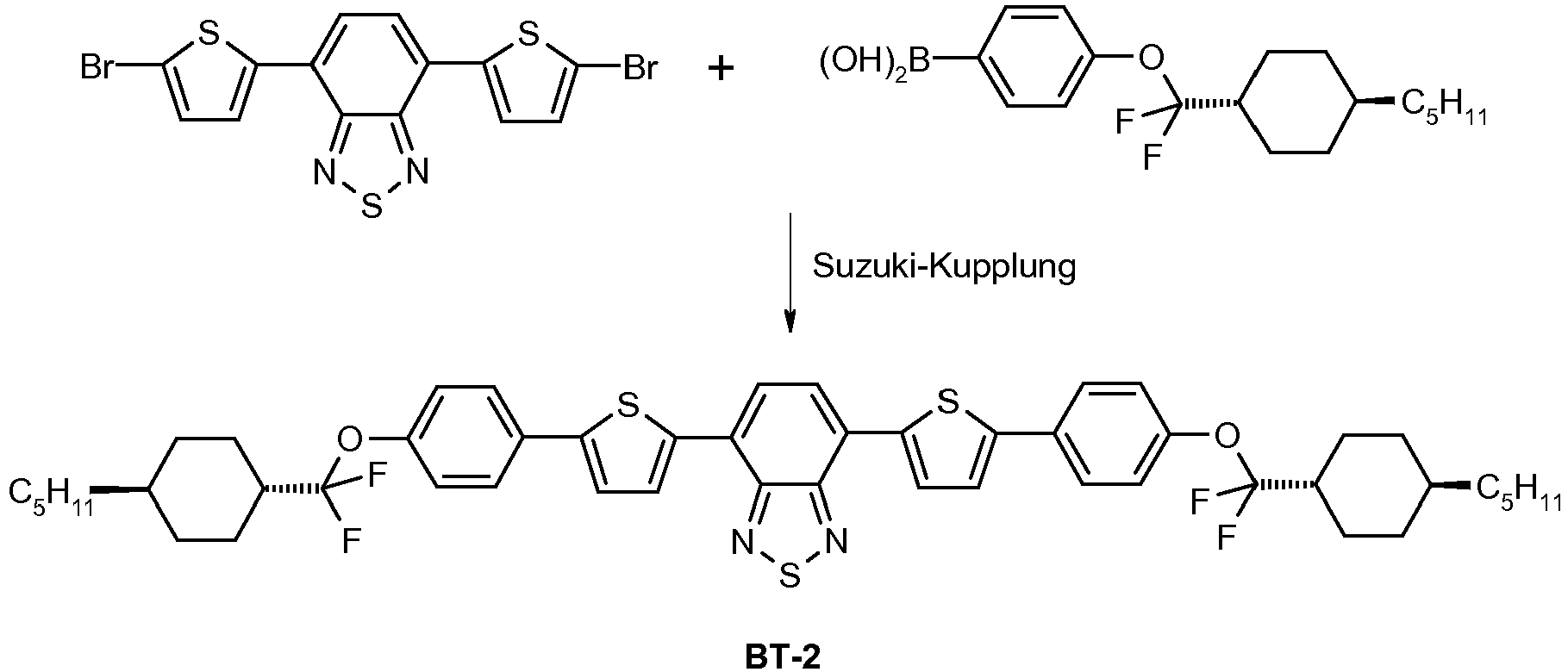
- Zur Synthese der Verbindung wird wie bei A-1) angegeben vorgegangen, mit dem Unterschied, dass lediglich 1.5 h unter Rückfluss erhitzt wird, bevor die Mischung aufgearbeitet wird. Die Umkristallisation erfolgt aus Toluol. Das Produkt wird als Pulver in einer Ausbeute von 29.5% d. Th. erhalten, die Reinheit laut HPLC ist 100 %. Die Identität des Produkts wird durch Massenspektroskopie bestätigt (m/z = 888).
-

- Zur Synthese der Verbindung wird wie bei A-1) angegeben vorgegangen. Die Umkristallisation erfolgt aus Isopropanol/Toluol 1:1. Das Produkt wird als Kristalle in einer Ausbeute von 45.1 % d. Th. erhalten, die Reinheit laut HPLC ist 99.4 %. Die Identität des Produkts wird durch Massenspektroskopie bestätigt (m/z = 616).
-

- Zur Synthese der Verbindung wird wie bei A-1) angegeben vorgegangen, mit dem Unterschied, dass 0.3 Äq. Aliquat 336 zusammen mit der Carbonatlösung zugegeben werden und aus Toluol umkristallisiert wird. Das Produkt wird in einer Ausbeute von 68.5 % d. Th. erhalten, die Reinheit laut HPLC ist 99.6 %. Die Identität des Produkts wird durch Massenspektroskopie bestätigt (m/z = 628).
-
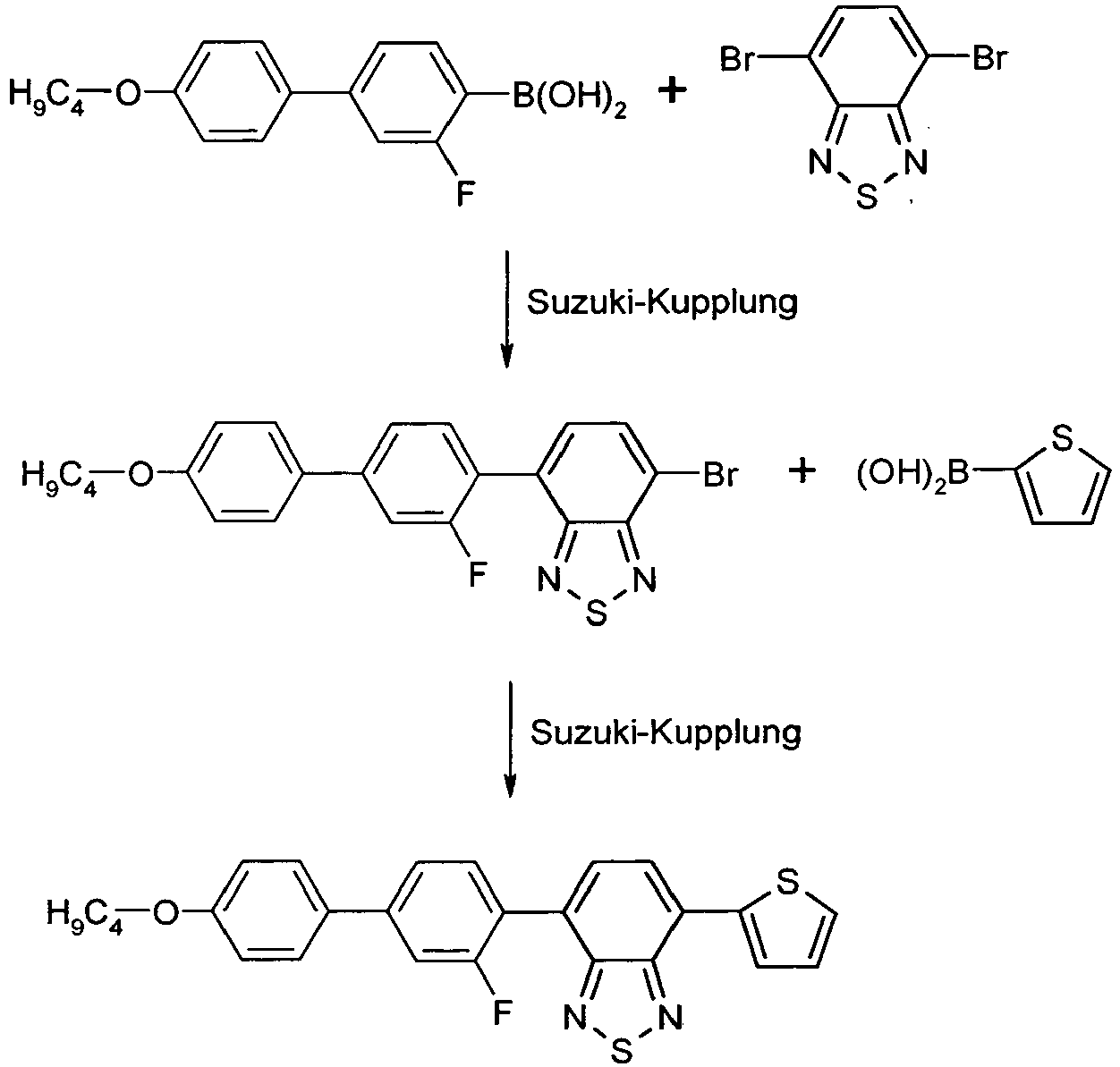
-

- Das Dibromid (33.8 mmol) und die Boronsäure (33.8 mmol) werden unter Stickstoff in 40 mL Toluol vorgelegt. Anschließend werden 67.7 mL einer 2.0 mol/L Lösung von Natriumcarbonat zugegeben. Anschließend wird Tris(dibenzyliden-aceton)dipalladium (0.34 mmol) und Tris-(o)-tolylphosphin (1.35 mmol) zugegeben, und die Mischung wird über Nacht unter Rückfluss gerührt. Anschließend lässt man den Ansatz abkühlen und trennt die wäßrige Phase ab. Die wäßrige Phase wird mit warmem Toluol extrahiert. Die vereinigten organischen Phasen werden zur Trockne eingeengt. Es wird mit 1-Chlorbutan über Kieselgel eluiert. Dann wird das Produkt aus Chlorbutan umkristallisiert. Das Produkt wird in einer Ausbeute von 38.7 % d. Th. und Reinheit von 99.8 % (HPLC) erhalten. Die Identität des Produkts wird durch Massenspektroskopie (m/z = 620) bestätigt.
- Es wird Natrium-Metaborat-Tetrahydrat (45.8 mmol) in 30 mL Wasser vorgelegt. Dann werden Bis-Triphenylphosphin-palladium(II)chlorid (0.5 mmol), Hydraziniumhydroxid (0.89 mmol) und die Boronsäure (14.4 mmol) und THF (80 mL) zugegeben und 5 min gerührt. Dann wird das Bromid (13.1 mmol) zugegeben und 3 h unter Rückfluss erhitzt. Anschließend wird die Mischung mit Wasser und Methyl-tert-Butyl-Ether versetzt und wäßrig aufgearbeitet. Nach Einengen der organischen Phasen zur Trockne wird das Produkt in einer Ausbeute von 90.9 % d. Th. und einer Reinheit von 97.9 % (HPLC) erhalten. Die Identität des Produkts wird durch Massenspektroskopie (m/z = 460) bestätigt.
- Das Thiophen-Derivat (11.9 mmol) wird in 60 mL 1,2-Dichlorbenzol unter N2 gelöst. Es wird N-Bromsuccinimid (12.5 mmol) unter Rühren zugegeben, und es wird auf 70 °C erhitzt. Anschließend lässt man 4 h bei dieser Temperatur rühren. Es wird abkühlen gelassen, dann wird mit 0.5 M NaOH-Lösung versetzt und 30 min gerührt. Der ausgefallene Feststoff wird isoliert und getrocknet. Das Produkt wird in einer Ausbeute von 87.8 % d. Th. und Reinheit von 97.4 % (HPLC) erhalten.
- Das Bromid (4.5 mmol) und die Boronsäure (4.9 mmol) werden unter Stickstoff in 50 mL Toluol vorgelegt. Anschließend werden 9.0 mL einer 2.0 mol/L Lösung von Natriumcarbonat zugegeben. Anschließend wird Tris(dibenzyliden-aceton)dipalladium (0.045 mmol) und Tris-(o)-tolylphosphin (0.18 mmol) zugegeben, und die Mischung wird über Nacht unter Rückfluss gerührt. Anschließend lässt man den Ansatz auf 40 °C abkühlen und trennt die wäßrige Phase ab. Die wäßrige Phase wird mit warmem Toluol extrahiert. Die vereinigten organischen Phasen werden aufkonzentriert und mit Chlorbutan über Kieselgel eluiert. Anschließend wird aus Chlorbutan umkristallisiert. Dabei wird das Produkt in einer Ausbeute von 61% d. Th. erhalten.
- Die Verbindungen BT-6 bis BT-17 können entsprechend hergestellt werden. Ihre Strukturen sind in der folgenden Tabelle 3 gezeigt.
-

- Der Diboronester (11,9 mmol) wurde in 150 ml Toluol unter Stickstoff vorgelegt und auf 60° erwärmt. Dazu wurde das entsprechende Bromid (29,7 mmol) gelöst in 50 ml Toluol auf ebenfalls 60° erwärmt und zugegeben. Nun wurde die zuvor auf 40° erwärmte 2 molare Natriumcarbonatlösung (94,8 mmol) rasch zugegeben. 0,95 mmol Tris(dibenzyliden-aceton-)dipalladium und 0,24 mmol Tris-(o)-tolylphoshin wurde danach hinzugefügt, rasch auf Rückflußtemperatur gebracht. Über Nacht wurde am Rückfluß gekocht. Es wurde auf 40° abgekühlt, die wässrige Phase abgetrennnt, die org.Phase 1x mit gesättigter NaCl-Lösung gewaschen. Der org.Extrakt wurde nun aufkonzentriert und mit einem Gemisch aus Toluol/Heptan (1:1) über Kieselgel chromatographiert. Anschließend wurden die gesammelten Fraktionen zum Rückstand eingeengt und mehrmals aus Toluol umkristallisiert.
Dabei konnten 379 mg Produkt (4,2% der Theorie) isoliert werden. Die Identität wurde durch Massenspektroskopie (M:722,65) und NMR bestätigt. -

- Zur Synthese der Verbindung BT-19 wird wie bei A-1) angegeben vorgegangen, Die Identität des Produkts wird durch Massenspektroskopie bestätigt (m/z = 741).
-

- Zur Synthese der Verbindung BT-20 wird wie bei A-1) angegeben vorgegangen, Die Identität des Produkts wird durch Massenspektroskopie bestätigt (m/z = 793).
-

- Zur Synthese der Verbindung BT-21 wird wie bei A-1) angegeben vorgegangen, Die Identität des Produkts wird durch Massenspektroskopie bestätigt (m/z = 945).
-

- Das Dichlorid (5,0 mmol) und die Boronsäure (10.0 mmol) werden unter Stickstoff in 40 mL Toluol vorgelegt. Anschließend werden 20.1 mL einer 2.0 mol/L Lösung von Natrium-tert-butylat zugegeben. Anschließend wird Tris(dibenzyliden-aceton)dipalladium (0.05 mmol) und Tricyclohexylphosphin (0.2 mmol) zugegeben, und die Mischung wird über Nacht unter Rückfluss gerührt. Anschließend lässt man den Ansatz auf 40 °C abkühlen und arbeitet wäßrig auf. Die vereinigten organischen Phasen werden aufkonzentriert und mit Toluol über Kieselgel eluiert. Anschließend wird aus Isopropanol/Toluol 1:4 umkristallisiert. Dabei wird das Produkt in einer Ausbeute von 4,5% d.Th. erhalten. Die Identität des Produkts wird durch Massenspektroskopie (m/z = 616) bestätigt.
Tabelle 3 BT-6 (Ref.) 
BT-7 
BT-8 
BT-9 
BT-10 
BT-11 
BT-12 
BT-13 
BT-14 
BT-15 
BT-16 
BT-17 
BT-18 (Ref.) 
BT-19 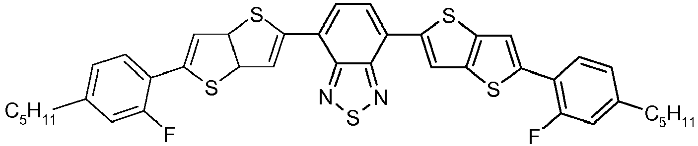
BT-20 
BT-21 (Ref.) 
BT-22 (Ref.) 
- Die hergestellten Farbstoffe werden auf ihre physikalischen Eigenschaften hin untersucht, um ihre Eignung zur Verwendung in Vorrichtungen zur Regulierung der Energie-Transmission festzustellen. Zum Vergleich werden die entsprechenden Eigenschaften für die Verbindung D-3 (Struktur siehe unten) angegeben.
- Die Lichtbeständigkeit wird wie folgt bestimmt: Es wird ein UV-VIS-Spektrum in einer versiegelten Messzelle zu Beginn der Belastung registriert. Dann wird die Probe belastet, indem sie intensivem Licht (Ausschluss von UV-Licht durch 400 nm cut-off Filter) in einem Suntest CPS+ der Firma MTS-Atlas ausgesetzt wird. In regelmäßigen Abständen wird ein erneutes Spektrum aufgenommen. Die Zeit, nach der der Extinktionswert der langwelligsten und vorzugsweise intensivsten Absorption auf unter 80% der Ausgangswertes abgesunken ist, wird zur Kennzeichnung der Lichtbeständigkeit angegeben.
- Als Stokes-Shift wird die Differenz zwischen der Wellenlänge des kurzwelligsten Emissionsmaximums und der Wellenlänge des langwelligsten Absorptionsmaximums angegeben.
Tabelle 4 Name Absorptions -Maximum / nm Anisotropiegrad R Stokes-Shift / nm Löslichkeit in Gew.-% in M-1 Lichtbeständigkeit BT-1 413 0.80 n. best. >0.50 2 Wochen BT-2 502 0.74 115 nm 0.30 32 Wochen BT-3 390 0.80 n. best. >0.50 1 Woche BT-4 505 0.71 125 0.75 39 Wochen BT-5 459 0.77 n. best. 3.90 12 Wochen BT-6 398 0.81 n. best. < 0.25 < 1 Woche BT-7 517 0.73 n. best. 0.30 22 Wochen BT-8 507 0.71 n. best. 0.40 27 Wochen BT-9 491 0.73 n. best. 0.30 9 Wochen BT-10 524 0.72 n. best. 0.30 18 Wochen BT-11 505 0.73 120 0.25 21 Wochen BT-12 515 0.74 125 0.25 25 Wochen BT-13 510 0.76 125 1.50 17 Wochen BT-14 495 0.69 120 1.60 13 Wochen BT-15 475 0.74 n. best. 3.80 8 Wochen BT-16 505 0.72 n. best. n. best. n. best. BT-17 463 0.67 n. best. n. best. n. best. BT-18 525 0.77 n. best. n. best. n. best. D-3 590 0.68 50 0.50 > 15 Wochen - Die Messungen zeigen, dass die erfindungsgemäßen Benzothiadiazol-Verbindungen hervorragende Eigenschaften in Bezug auf Anisotropiegrad, Löslichkeit in flüssigkristallinen Medien und Stokes-Shift aufweisen. Desweiteren weisen die erfindungsgemäßen Verbindungen, mit mindestens einem Schwefel enthaltenen Heterozyklus direkt an den Benzothiadiazolrest gebunden, eine besonders hohe Lichtbeständigkeit auf. Weiterhin haben sie abhängig vom Substitutionsmuster unterschiedliche Absorptionsfarben, so dass eine Mischung enthaltend zwei oder mehr der erfindungsgemäßen Farbstoffe bereits einen großen Teil des sichtbaren Spektrums abdeckt. Wird ein als weiterer Farbstoff ein rot absorbierender Farbstoff hinzugefügt, kann eine schwarze Mischung erhalten werden.
- Der hohe Stokes-Shift der Verbindungen macht es möglich, eine hohe Fluoreszenzausbeute zu erreichen, da nur geringe Re-Absorption der Fluoreszenz stattfindet. Dies ist ein großer Vorteil bei Verwendung der Verbindungen in Vorrichtungen, bei denen die Fluoreszenzstrahlung zur Gewinnung von Energie (autonome Vorrichtungen zur Regulierung der Energietransmission in Fenstern mit Solarzellen, vgl.
WO 2009/141295 ) genutzt wird. - Es werden die folgenden Farbstoffe in den angegebenen Anteilen zur Grundmischung M-1 (s. u.) hinzugegeben und eine Lösung hergestellt:
Tabelle 5 Farbstoff Anteil BT-4 0.20 Gew.-% D-1 0.49 Gew.-% D-2 0.35 Gew.-% D-3 0.35 Gew.-% -
Tabelle 6 M-1 Klärpunkt 114.5 °C Delta-n 0.1342 ne 1.6293 no 1.4951 Zusammensetzung Verbindung Gew.-% CPG-3-F 5 CPG-5-F 5 CPU-3-F 15 CPU-5-F 15 CP-3-N 16 CP-5-N 16 CCGU-3-F 7 CGPC-3-3 4 CGPC-5-3 4 CGPC-5-5 4 CCZPC-3-3 3 CCZPC-3-4 3 CCZPC-3-5 3 -
Tabelle 7 
D-1 
D-2 
D-3 - Um die Vorrichtung herzustellen, wird die Flüssigkristallmischung enthaltend die Farbstoffe (LC-1) in den Zwischenraum der folgenden Schichtenanordnung gefüllt:
- Substratschicht
- ITO-Schicht
- Polyimid-Orientierungsschicht
- mit Spacern offengehaltener Zwischenraum
- Polyimid-Orientierungsschicht
- ITO-Schicht
- Substratschicht
- Die Flüssigkristallschicht ist in dieser Anordnung planar mit antiparallelem Pretiltwinkel orientiert. Diese Orientierung wird durch zwei antiparallel zueinander geriebene Polyimidschichten erreicht. Die Dicke der flüssigkristallinen Schicht wird durch Spacer definiert und beträgt üblicherweise 25 µm.
- Es werden Werte für den Lichttransmissionsgrad τv jeweils für den dunklen und den hellen Schaltzustand der Vorrichtung ermittelt und im Folgenden aufgeführt. Der helle Schaltzustand wird durch Anlegen einer Spannung erreicht, während der dunkle Schaltzustand ohne Spannung vorliegt. Weiterhin wird der Farbort der Vorrichtung (in CIE-Koordinaten) im Dunkel- und im Hellzustand ermittelt.
- Die Messung erfolgt mit der Vorrichtung enthaltend das flüssigkristalline Medium mit Farbstoffen im Messstrahl und einer baugleichen Vorrichtung, entsprechend ohne die Farbstoffe im Referenzstrahl. Hierdurch werden Reflexions- und Absorptionsverluste der Zelle eliminiert.
- Der Wert τv und die CIE-Koordinaten (x,y) sind wie folgt definiert:
τv= Lichttransmissionsgrad, bestimmt nach DIN EN410
Der Farbort (für weiß, grau schwarz) der hier zugrundegelegten Normlichtart D65 liegt bei x=0.3127 und y=0.3290 (Manfred Richter, Einführung in die Farbmetrik, zweite Auflage 1991, ISBN 3-11-008209-8). Die angegebenen Farborte (x,y) beziehen sich alle auf die Normlichtart D65 und den 2° Normalbeobachter nach CIE 1931. - Erhaltene Messwerte für die Vorrichtung:
- Dunkelzustand: x=0.312; y= 0.324; τv =33%
- Hellzustand: x=0.319; y=0.336; τv =60%
- Im Beispiel zeigt sich eine gute Stabilität des flüssigkristallinen Mediums und eine genügende Löslichkeit der Farbstoffe im flüssigkristallinen Medium.
- Weiterhin zeigt das Beispiel, dass sich die Vorrichtung durch Anlegen einer Spannung von einem Dunkelzustand mit deutlich geringerer Lichttransmission zu einem Hellzustand mit deutlich erhöhter Lichttransmission schalten lässt.
- Zur Messung der relativen Fluoreszenz aus Wellenleitung wird eine Mischung des jeweiligen Farbstoffs in der flüssigkristallinen Grundmischung M-1 hergestellt. Dabei wird die Konzentration in allen Fällen so gewählt, dass eine Transmission von 35% durch die Mischung erhalten wird. Die Mischung wird in eine Zelle mit antiparallelen Orientierungsschichten gefüllt. (Schichtdicke 25 Mikrometer). Die Zelle wird mit einer Halogenlampe (300W) belichtet. Es wird die durch Wellenleitung weitergeleitete Lichtmenge an Fluoreszenzemission an den Kanten parallel und senkrecht zur Orientierungsachse einzeln gemessen und anschließend gemittelt. Hierzu wird das Licht in eine Ulbrichtkugel geleitet und mit einem Spektrometer gemessen. Es wird die Fläche unter dem Emissionsspektrum gebildet und mit dem der Referenzsubstanz D-3 verglichen. Der Vergleich wird als Relativwert in Prozent angegeben, der sich aus den Quotienten der Flächen Messung vs. Referenz ergibt.
- Dabei werden für die unten genannten erfindungsgemäßen Verbindungen die folgenden Werte erhalten:
Tabelle 8 Name relative Fluoreszenz aus Wellenleitung BT-4 108% BT-8 106% BT-9 110% BT-11 111% BT-12 113% BT-13 113% BT-14 111% - Die erfindungsgemäßen Verbindungen zeigen bei Verwendung in einer Vorrichtung zur Regulierung des Energie-Durchtritts, bei der die absorbierte Lichtenergie über Fluoreszenz wieder emittiert wird, eine hervorragende Fluoreszenzlicht-Ausbeute an den Kanten der Vorrichtung. Damit kann an diesen Stellen das Fluoreszenzlicht aufgenommen und in elektrische Energie umgewandelt werden, beispielsweise mittels Solarzellen. Auf diese Weise können Vorrichtungen zur Regulierung des Energie-Durchtritts erhalten werden, welche autonom, d.h. unabhängig von äußerer Energiezufuhr, geschaltet werden können, da sie absorbierte Lichtenergie über Fluoreszenzemission und anschließende Umwandlung des Fluoreszenzlichts in elektrische Energie zur eigenen Energieversorgung nutzen können.
Claims (14)
- Vorrichtung zur Regulierung des Durchtritts von von der Sonne ausgehendem Licht von einem Außenraum in einen Innenraum hinein, wobei die Vorrichtung eine Schaltschicht umfasst, welche ein flüssigkristallines Medium enthaltend eine oder mehrere verschiedene Verbindungen und mehrere dichroitische Farbstoffe einer Formel (I)

 X ist bei jedem Auftreten gleich oder verschieden CR2 oder N;Y ist gleich S oder Se;Z1 ist eine Einfachbindung;Z2 ist bei jedem Auftreten gleich oder verschieden eine Einfachbindung, O, S, C(R3)2, -CR3=CR3- oder -C≡C-; oder zwei, drei, vier oder fünf miteinander kombinierte Gruppen, gewählt aus den Gruppen O, S, C(R3)2, -CR3=CR3- und -C≡C-;Ar1 ist bei jedem Auftreten gleich oder verschieden eine Aryl- oder Heteroarylgruppe mit 5 bis 30 aromatischen Ringatomen, die mit einem oder mehreren Resten R4 substituiert sein kann, wobei jeweils mindestens ein Ar1 gewählt ist aus einer schwefelhaltigen Heteroarylgruppe, die mit einem oder mehreren Resten R4 substituiert sein kann;R1 ist bei jedem Auftreten gleich oder verschieden H, D, F, CN, N(R5)2, oder eine Alkyl-, Alkoxy- oder Thioalkoxygruppe mit 1 bis 10 C-Atomen, die mit einem oder mehreren Resten R5 substituiert sein kann, wobei eine oder mehrere CH2-Gruppen in den Alkyl-, Alkoxy- oder Thioalkoxygruppen durch -R5C=CR5-, -C≡C-, C=O, C=S, -C(=O)O-, -OC(=O)-, Si(R5)2, NR5, -O- oder -S- ersetzt sein können;R2 ist bei jedem Auftreten gleich oder verschieden H, D, F, Cl, CN, -(C=O)OR5, -O(C=O)R5 oder eine Alkyl-, Alkoxy- oder Thioalkoxygruppe mit 1 bis 10 C-Atomen, die mit einem oder mehreren Resten R5 substituiert sein kann, wobei eine oder mehrere CH2-Gruppen in den Alkyl-, Alkoxy- oder Thioalkoxygruppen durch -R5C=CR5-, -C≡C-, C=O, C=S, -C(=O)O-, -OC(=O)-, Si(R5)2, NR5, -O- oder -S- ersetzt sein können;R3, R4 sind bei jedem Auftreten gleich oder verschieden H, D, F, Cl, CN, oder eine Alkyl-, Alkoxy-, oder Thioalkoxygruppe mit 1 bis 10 C-Atomen, die mit einem oder mehreren Resten R5 substituiert sein kann, wobei eine oder mehrere CH2-Gruppen in den Alkyl-, Alkoxy- oder Thioalkoxygruppen durch -R5C=CR5-, -C≡C-, C=O, C=S, -C(=O)O-, -OC(=O)-, Si(R5)2, NR5, -O- oder -S- ersetzt sein können;R5 ist bei jedem Auftreten gleich oder verschieden H, D, F, Cl, CN, N(R6)2, eine Alkyl-, Alkoxy- oder Thioalkoxygruppe mit 1 bis 10 C-Atomen oder eine Alkenyl- oder Alkinylgruppe mit 2 bis 20 C-Atomen, wobei die oben genannten Gruppen jeweils mit einem oder mehreren Resten R6 substituiert sein können und wobei eine oder mehrere CH2-Gruppen in den oben genannten Gruppen durch -R6C=CR6-, -C≡C-, C=O, C=S, -C(=O)O-, -O(C=O)-, Si(R6)2, NR6, -O- oder -S- ersetzt sein können, oder eine Aryl- oder Heteroarylgruppe mit 5 bis 30 aromatischen Ringatomen, die jeweils mit einem oder mehreren Resten R6 substituiert sein kann;R6 ist bei jedem Auftreten gleich oder verschieden H, F oder ein aliphatischer organischer Rest mit 1 bis 20 C-Atomen, in dem ein oder mehrere H-Atome durch F ersetzt sein können, oder eine Aryl- oder Heteroarylgruppe mit 5 bis 20 C-Atomen, in der ein oder mehrere H-Atome durch F ersetzt werden können;i ist gleich 0, 1, 2, 3, 4 oder 5,wobei das flüssigkristalline Medium der Schaltschicht einen Klärpunkt im Temperaturbereich von 70 °C bis 170 °C hat.
 - Vorrichtung nach Anspruch 1, dadurch gekennzeichnet, dass X gleich CR2 ist.
- Vorrichtung nach Anspruch 1 oder 2, dadurch gekennzeichnet, dass Y gleich S ist.
- Vorrichtung nach einem oder mehreren der Ansprüche 1 bis 3, dadurch gekennzeichnet, dass Z2 bei jedem Auftreten gleich oder verschieden für eine Einfachbindung, -C(R3)2C(R3)2-, -CR3=CR3-, -C≡C-, -OC(R3)2- oder -C(R3)2O- steht.
- Vorrichtung nach einem oder mehreren der Ansprüche 1 bis 4, dadurch gekennzeichnet, dass die in Anspruch 1 definierte Gruppe Ar1 bei jedem Auftreten gleich oder verschieden eine Arylgruppe mit 6 bis 15 C-Atomen oder eine Heteroarylgruppe mit 5 bis 15 C-Atomen darstellt, die mit einem oder mehreren Resten R4 substituiert sein kann.
- Vorrichtung nach einem oder mehreren der Ansprüche 1 bis 5, dadurch gekennzeichnet, dass die in Anspruch 1 oder 5 definierte Gruppe Ar1 bei jedem Auftreten gleich oder verschieden gewählt ist aus wahlweise mit Resten R4 substituiertem Benzol, Fluoren, Naphthalin, Pyridin, Pyrimidin, Pyrazin, Triazin, Thiophen, Thiophen mit ankondensiertem 1,4-Dioxanring, Benzothiophen, Dibenzothiophen, Benzodithiophen, Cyclopentadithiophen, Thienothiophen, Indenothiophen, Dithienopyrrol, Silolodithiophen, Selenophen, Benzoselenophen, Dibenzoselenophen, Furan, Benzofuran, Dibenzofuran und Chinolin.
- Vorrichtung nach einem oder mehreren der Ansprüche 1 bis 6, dadurch gekennzeichnet, dass R1 bei jedem Auftreten gleich oder verschieden ist H, F, oder eine geradkettige Alkyl- oder Alkoxylgruppe mit 3 bis 8 C-Atomen, die mit einem oder mehreren Resten R5 substituiert sein kann, oder eine verzweigte Alkyl- oder Alkoxygruppe mit 3 bis 8 C-Atomen, die mit einem oder mehreren Resten R5 substituiert sein kann, oder eine cyclische Alkylgruppe mit 6 C-Atomen, die mit einem oder mehreren Resten R5 substituiert sein kann, wobei in den Alkyl- und Alkoxygruppen eine oder mehrere CH2-Gruppen durch -O-, -S- oder -R5C=CR5- ersetzt sein können, oder eine Siloxanylgruppe mit 1 bis 6 Si-Atomen, die mit einem oder mehreren Resten R5 substituiert sein kann.
- Vorrichtung nach einem oder mehreren der Ansprüche 1 bis 7, dadurch gekennzeichnet, dass der Index i gleich 1 oder 2 ist.
- Vorrichtung nach einem oder mehreren der Ansprüche 1 bis 8, dadurch gekennzeichnet, dass der Anisotropiegrad R der Verbindung der Formel (I) oder Formel (II), ermittelt wie in den Ausführungsbeispielen angegeben, größer ist als 0.4.
- Vorrichtung nach einem oder mehreren der Ansprüche 1 bis 9, dadurch gekennzeichnet, dass sie elektrisch schaltbar ist.
- Vorrichtung nach einem oder mehreren der Ansprüche 1 bis 10, dadurch gekennzeichnet, dass sie mit einer Solarzelle oder einer sonstigen Vorrichtung zur Umwandlung von Licht und/oder Wärmeenergie in elektrische Energie verbunden ist.
- Fenster, enthaltend eine Vorrichtung nach einem oder mehreren der Ansprüche 1 bis 11.
- Verbindung gemäß Formel (Ia) oder (Ib)


die auftretenden Gruppen R4 und R5 sind definiert wie für Formel (I) in Anspruch 1, undR7 ist bei jedem Auftreten gleich oder verschieden Wasserstoff oder eine Alkylgruppe mit 1 bis 5 C-Atomen, die mit einem oder mehreren Resten R6 substituiert sein kann;k ist, gleich oder verschieden bei jedem Auftreten, 0, 1, 2, 3 oder 4;m ist, gleich oder verschieden bei jedem Auftreten, 0, 1, 2, 3, 4, 5 oder 6;n ist, gleich oder verschieden bei jedem Auftreten, 1, 2, 3, 4 oder 5. - Verwendung einer Mischung, welche ein flüssigkristallines Medium und mehrere Verbindungen der wie in Anspruch 1 angegebenen Formel (I) oder Formel (II) enthält, in einer Vorrichtung zur Regulierung des Energie-Durchtritts in Form von von der Sonne ausgehendem Licht von einem Außenraum in einen Innenraum, wobei das flüssigkristalline Medium einen Klärpunkt im Temperaturbereich von 70 °C bis 170 °C hat.
Priority Applications (1)
| Application Number | Priority Date | Filing Date | Title |
|---|---|---|---|
| EP14721765.7A EP3004251B1 (de) | 2013-05-24 | 2014-04-29 | Vorrichtung zur regulierung des energie-durchtritts enthaltend eine dichroitische farbstoffverbindung |
Applications Claiming Priority (3)
| Application Number | Priority Date | Filing Date | Title |
|---|---|---|---|
| EP13002711 | 2013-05-24 | ||
| EP14721765.7A EP3004251B1 (de) | 2013-05-24 | 2014-04-29 | Vorrichtung zur regulierung des energie-durchtritts enthaltend eine dichroitische farbstoffverbindung |
| PCT/EP2014/001149 WO2014187529A1 (de) | 2013-05-24 | 2014-04-29 | Vorrichtung zur regulierung des energie-durchtritts enthaltend eine dichroitische farbstoffverbindung |
Publications (2)
| Publication Number | Publication Date |
|---|---|
| EP3004251A1 EP3004251A1 (de) | 2016-04-13 |
| EP3004251B1 true EP3004251B1 (de) | 2019-03-13 |
Family
ID=48576683
Family Applications (1)
| Application Number | Title | Priority Date | Filing Date |
|---|---|---|---|
| EP14721765.7A Active EP3004251B1 (de) | 2013-05-24 | 2014-04-29 | Vorrichtung zur regulierung des energie-durchtritts enthaltend eine dichroitische farbstoffverbindung |
Country Status (7)
| Country | Link |
|---|---|
| US (1) | US10344217B2 (de) |
| EP (1) | EP3004251B1 (de) |
| JP (1) | JP6563384B2 (de) |
| KR (1) | KR102234246B1 (de) |
| CN (1) | CN105377995B (de) |
| TW (1) | TWI654259B (de) |
| WO (1) | WO2014187529A1 (de) |
Families Citing this family (40)
| Publication number | Priority date | Publication date | Assignee | Title |
|---|---|---|---|---|
| KR102332049B1 (ko) * | 2014-04-11 | 2021-11-30 | 메르크 파텐트 게엠베하 | 액정 물질 |
| CN106795318B (zh) * | 2014-08-12 | 2020-07-14 | 飞利斯有限公司 | 分子半导体和聚合物半导体及相关器件 |
| EP3230406B1 (de) * | 2014-12-09 | 2018-10-10 | Merck Patent GmbH | Vorrichtung zur regulierung des energie-durchtritts |
| EP3289408B1 (de) | 2015-04-27 | 2020-12-16 | Merck Patent GmbH | Optische schaltschicht für den einsatz in einem optischen schaltelement |
| DE102015005800A1 (de) * | 2015-05-06 | 2016-11-10 | Merck Patent Gmbh | Thiadiazolochinoxalinderivate |
| JP6884748B2 (ja) * | 2015-07-10 | 2021-06-09 | メルク パテント ゲゼルシャフト ミット ベシュレンクテル ハフツングMerck Patent Gesellschaft mit beschraenkter Haftung | ジチオアルキルピロロピロール類および色素としてのその使用 |
| EP3440156B1 (de) * | 2016-04-08 | 2020-01-01 | Merck Patent GmbH | Zwischenprodukte und verfahren zur synthese von funktionswerkstoffen |
| CN110199007B (zh) | 2016-06-10 | 2023-02-28 | 美国陶氏有机硅公司 | 非线性侧链液晶聚有机硅氧烷和其制备方法以及在电光应用和装置中的用途 |
| EP3260913B1 (de) * | 2016-06-22 | 2021-09-15 | Merck Patent GmbH | Optische schaltvorrichtung |
| US10982150B2 (en) | 2016-06-28 | 2021-04-20 | Merck Patent Gmbh | Liquid crystalline medium |
| CN109476994B (zh) | 2016-07-20 | 2023-02-10 | 默克专利股份有限公司 | 用于光学切换元件的切换层 |
| TWI609213B (zh) * | 2016-12-14 | 2017-12-21 | 國立中山大學 | 可調式隔熱窗戶 |
| WO2018206545A1 (en) | 2017-05-09 | 2018-11-15 | Merck Patent Gmbh | Optical device comprising a switchable layer and at least one optical layer |
| JP7293130B2 (ja) | 2017-05-11 | 2023-06-19 | メルク・パテント・ゲゼルシヤフト・ミツト・ベシユレンクテル・ハフツング | 液晶媒体 |
| CN110178239B (zh) | 2017-06-23 | 2023-06-20 | 株式会社Lg化学 | 有机太阳能电池 |
| EP3557640B1 (de) | 2017-06-23 | 2022-10-12 | LG Chem, Ltd. | Organische solarzelle |
| JP7014549B2 (ja) * | 2017-09-07 | 2022-02-01 | 信一郎 礒部 | 蛍光色素 |
| WO2019110473A1 (en) | 2017-12-04 | 2019-06-13 | Merck Patent Gmbh | Liquid-crystal medium |
| JP7307064B2 (ja) | 2017-12-06 | 2023-07-11 | メルク・パテント・ゲゼルシヤフト・ミツト・ベシユレンクテル・ハフツング | スイッチング素子に使用するための液晶媒体 |
| EP3720924A1 (de) | 2017-12-06 | 2020-10-14 | Merck Patent GmbH | Flüssigkristallines medium zur verwendung in einem schaltelement |
| CN108333813B (zh) * | 2018-03-05 | 2021-09-14 | 京东方科技集团股份有限公司 | 一种电子窗及其控制方法 |
| CN112236882B (zh) | 2018-03-28 | 2023-06-30 | 天光材料科技股份有限公司 | 有机半导体化合物 |
| US12532662B2 (en) | 2018-03-28 | 2026-01-20 | Raynergy Tek Incorporation | Organic semiconducting compounds |
| KR102756999B1 (ko) * | 2018-06-20 | 2025-01-22 | 메르크 파텐트 게엠베하 | 액정 매질 |
| CN113195684B (zh) * | 2018-09-25 | 2024-10-29 | 默克专利股份有限公司 | 偶氮染料 |
| CN113166652B (zh) * | 2018-11-23 | 2025-01-21 | 默克专利股份有限公司 | 二色性染料组合物 |
| KR102239212B1 (ko) * | 2018-12-14 | 2021-04-12 | 주식회사 엘지화학 | 포토폴리머 조성물 |
| WO2020127141A1 (en) | 2018-12-19 | 2020-06-25 | Merck Patent Gmbh | Switching layers for use in a switching element |
| CN113874469B (zh) | 2019-05-15 | 2024-09-10 | 默克专利股份有限公司 | 制备基于液晶的切换元件的方法 |
| CN114008176A (zh) * | 2019-06-17 | 2022-02-01 | 默克专利股份有限公司 | 基于液晶的光阀 |
| EP3839620B1 (de) | 2019-12-16 | 2025-02-26 | Merck Patent GmbH | Vorrichtung zur regelung der lichttransmission |
| EP4259747B1 (de) | 2020-12-11 | 2024-10-30 | Merck Patent GmbH | Vorrichtung zur regelung der lichttransmission |
| TW202317855A (zh) | 2021-08-06 | 2023-05-01 | 德商馬克專利公司 | 用於窗元件之切換層 |
| WO2023094404A1 (en) | 2021-11-24 | 2023-06-01 | Merck Patent Gmbh | Liquid crystal medium and liquid crystal display |
| KR20240132854A (ko) * | 2023-02-27 | 2024-09-04 | 주식회사 엘지화학 | 액정 조성물 |
| EP4720220A1 (de) | 2023-06-05 | 2026-04-08 | Merck Patent GmbH | Flüssigkristallines medium |
| WO2025061649A1 (en) | 2023-09-20 | 2025-03-27 | Merck Patent Gmbh | Liquid crystal medium |
| KR20250113342A (ko) | 2024-01-18 | 2025-07-25 | 메르크 파텐트 게엠베하 | 액정 매질 |
| WO2025190813A1 (en) | 2024-03-11 | 2025-09-18 | Merck Patent Gmbh | Liquid-crystal medium |
| WO2026052594A1 (en) | 2024-09-05 | 2026-03-12 | Merck Patent Gmbh | Liquid crystal-based light valve |
Citations (1)
| Publication number | Priority date | Publication date | Assignee | Title |
|---|---|---|---|---|
| WO2013097919A1 (de) * | 2011-12-27 | 2013-07-04 | Merck Patent Gmbh | Vorrichtung zur temperaturabhängigen regulierung des energie - durchtritts durch eine lichtdurchlässige fläche |
Family Cites Families (51)
| Publication number | Priority date | Publication date | Assignee | Title |
|---|---|---|---|---|
| JPS55123673A (en) | 1979-03-16 | 1980-09-24 | Mitsui Toatsu Chem Inc | Liquid crystal color display device |
| JPS55152875A (en) | 1979-05-14 | 1980-11-28 | Mitsubishi Chem Ind | Anthraquinone dyestuff for cellulose containing fibers |
| JPS5652440U (de) | 1979-09-29 | 1981-05-09 | ||
| GB2065695B (en) | 1979-10-12 | 1984-07-25 | Hitachi Ltd | Guest-host type liquid crystal composition and liquid crystal display device using the same |
| JPS5657850A (en) | 1979-10-18 | 1981-05-20 | Nippon Kanko Shikiso Kenkyusho:Kk | Azo compound and dichromatic dye for liquid crystal consisting of the same |
| GB2065158A (en) | 1979-12-13 | 1981-06-24 | Standard Telephones Cables Ltd | Anthraquinone Dichroic Dyes |
| JPS56104984A (en) | 1980-01-24 | 1981-08-21 | Nippon Kanko Shikiso Kenkyusho:Kk | Bichromic pigment for yellow liquid crystal |
| DE3007198A1 (de) | 1980-02-26 | 1981-09-03 | Siemens AG, 1000 Berlin und 8000 München | Pleochroitischer anthrachinon-farbstoff, verfahren zu seiner herstellung und verwendung des farbstoffs |
| US4350603A (en) | 1980-06-30 | 1982-09-21 | General Electric Company | Novel tris-azo dyes and liquid crystal compositions made therewith |
| EP0043904A3 (de) | 1980-07-10 | 1982-03-31 | F. HOFFMANN-LA ROCHE & CO. Aktiengesellschaft | Farbstoffhaltige Mischungen, neue Farbstoffe und deren Verwendung in Flüssigkristallmischungen |
| GB2082196B (en) | 1980-07-29 | 1985-01-23 | Secr Defence | Liquid crystal materials containing anthraquinone pleochroic dyes |
| GB2081736B (en) | 1980-07-29 | 1985-02-20 | Secr Defence | Liquid crystal materials containing diamino-dihydroxy anthraquinone pleochroic dyes |
| EP0044893B1 (de) | 1980-07-29 | 1984-09-19 | Imperial Chemical Industries Plc | Anthrachinon-Verbindungen und Verfahren zu ihrer Herstellung |
| US4308161A (en) | 1980-08-04 | 1981-12-29 | General Electric Company | Novel yellow azo dyes and dichroic liquid crystal compositions made therewith |
| EP0047027A1 (de) | 1980-08-22 | 1982-03-10 | BBC Aktiengesellschaft Brown, Boveri & Cie. | Flüssigkristallmischung |
| JPS5755984A (en) | 1980-09-22 | 1982-04-03 | Hitachi Ltd | Liquid crystal composition |
| JPS5763377A (en) | 1980-10-03 | 1982-04-16 | Mitsui Toatsu Chem Inc | Liquid crystal composition for color display |
| DE3040102A1 (de) | 1980-10-24 | 1982-06-03 | Merck Patent Gmbh, 6100 Darmstadt | Dichroitische anthrachinonfarbstoffe, diese enthaltende fluessigkristalline dielektrika und elektrooptisches anzeigeelement |
| US4308162A (en) | 1980-12-08 | 1981-12-29 | General Electric Company | Novel yellow azo dyes and dichroic liquid crystal compositions made therewith |
| DE3046904A1 (de) | 1980-12-12 | 1982-07-15 | Bayer Ag, 5090 Leverkusen | Anthrachinonfarbstoffe, verfahren zu ihrer herstellung ihre verwendung sowie fluessigkristalline materialien enthaltend anthrachinonfarbstoffe |
| DE3115147A1 (de) | 1981-04-15 | 1982-11-04 | Basf Ag, 6700 Ludwigshafen | Farbstoffe fuer fluessigkristallmischungen |
| EP0056492B1 (de) | 1981-01-10 | 1984-12-12 | BASF Aktiengesellschaft | Farbstoffe für Flüssigkristallmischungen |
| JPS57126879A (en) | 1981-01-12 | 1982-08-06 | Sumitomo Chem Co Ltd | Liquid crystal display element |
| DE3201120A1 (de) | 1981-01-17 | 1982-10-21 | Hitachi, Ltd., Tokyo | Fluessigkristall-zusammensetzung |
| GB2094822B (en) | 1981-02-25 | 1986-03-05 | Ici Plc | Anthraquinone dyes |
| EP0142617B1 (de) | 1981-02-25 | 1987-07-22 | Imperial Chemical Industries Plc | Pleochroitische Anthrachinonfarbstoffe |
| DE3110960A1 (de) | 1981-03-20 | 1982-09-30 | Basf Ag, 6700 Ludwigshafen | Elektrophotographisches aufzeichnungsmaterial |
| DE3115762A1 (de) | 1981-04-18 | 1982-11-11 | Merck Patent Gmbh, 6100 Darmstadt | "dichroitische anthrachinonfarbstoffe, diese enthaltende fluessigkristalline dielektrika und elektrooprisches anzeigeelement" |
| DE3123519A1 (de) | 1981-06-13 | 1982-12-30 | Bayer Ag, 5090 Leverkusen | Fluessigkristallines material enthaltend azofarbstoffe |
| JPS581775A (ja) | 1981-06-26 | 1983-01-07 | Mitsubishi Chem Ind Ltd | 液晶組成物 |
| DE3126108A1 (de) | 1981-07-02 | 1983-01-20 | Merck Patent Gmbh, 6100 Darmstadt | "fluessigkristallines dielektrikum, neue dichroitische naphthochinonfarbstoffe und elektrooptisches anzeigeelement" |
| DE3202761A1 (de) | 1982-01-28 | 1983-08-04 | Merck Patent Gmbh, 6100 Darmstadt | Fluessigkristallines dielektrikum, neue farbstoffe, verfahren zu ihrer herstellung und elektrooptisches anzeigeelement |
| US6025897A (en) | 1993-12-21 | 2000-02-15 | 3M Innovative Properties Co. | Display with reflective polarizer and randomizing cavity |
| EP0698649A1 (de) | 1994-08-26 | 1996-02-28 | Basf Aktiengesellschaft | Verwendung von thermoplastisch verarbeitbaren, langzeitstabilen elektrolumineszenten Materialien |
| US6099758A (en) | 1997-09-17 | 2000-08-08 | Merck Patent Gesellschaft Mit Beschrankter Haftung | Broadband reflective polarizer |
| US7023602B2 (en) | 1999-05-17 | 2006-04-04 | 3M Innovative Properties Company | Reflective LCD projection system using wide-angle Cartesian polarizing beam splitter and color separation and recombination prisms |
| DE19957193A1 (de) * | 1998-12-04 | 2000-06-08 | Merck Patent Gmbh | Flüssigkristallmedium und dieses Medium enthaltende Flüssigkristallanzeige |
| JP2003104976A (ja) * | 2001-07-24 | 2003-04-09 | Mitsubishi Chemicals Corp | ベンゾチアジアゾール誘導体、液晶組成物、液晶表示素子、波長変換素子、エレクトロルミネッセンス素子、電荷輸送材料、および光電変換素子 |
| DE10229370A1 (de) * | 2002-06-29 | 2004-01-15 | Covion Organic Semiconductors Gmbh | 2,1,3-Benzothiadiazole |
| US7202926B2 (en) * | 2002-08-26 | 2007-04-10 | Dai Nippon Printing Co., Ltd. | Cholesteric reflective retardation optical element with directors at top surface of optical element parallel to those at the bottom surface of the optical element |
| EP1843407A1 (de) | 2006-04-07 | 2007-10-10 | Basf Aktiengesellschaft | Flüssig-kristalline Rylentetracarbonsäurederivate und deren Verwendung |
| US7826009B2 (en) | 2006-12-21 | 2010-11-02 | 3M Innovative Properties Company | Hybrid polarizer |
| HUE029288T2 (en) | 2007-10-30 | 2017-02-28 | Univ Florida | Green - Transmissive Soluble Electrochemical Polymers |
| US8927856B2 (en) | 2008-05-21 | 2015-01-06 | Peer+B.V. | Optical device with anisotropic luminescent material |
| EP2166040A1 (de) | 2008-09-22 | 2010-03-24 | Radiant Color N.V. | Neue lipophile fluoreszierende Farbstoffe und ein Prozess für ihre Produktion |
| ES2616252T3 (es) | 2009-04-10 | 2017-06-12 | Ravenbrick, Llc | Filtro óptico conmutado térmicamente que incorpora una arquitectura de huésped-hospedador |
| GB201009488D0 (en) * | 2010-06-07 | 2010-07-21 | Merck Patent Gmbh | Switch element comprising a liquid-crystaline medium |
| PL2630217T3 (pl) | 2010-10-20 | 2017-05-31 | Merck Patent Gmbh | Element przełączalny zawierający ciekłokrystaliczny ośrodek |
| US9249356B2 (en) | 2011-07-05 | 2016-02-02 | Peer+ B.V. | Liquid crystal dye mixture |
| ITMI20111268A1 (it) | 2011-07-07 | 2013-01-08 | Eni Spa | Concentratore solare luminescente comprendente composti benzoselenadiazolici disostituiti |
| ITMI20111516A1 (it) | 2011-08-08 | 2013-02-09 | Eni Spa | Procedimento per la preparazione di composti benzoetero[1,3]diazolici disostituiti con gruppi eteroarilici |
-
2014
- 2014-04-29 CN CN201480029535.XA patent/CN105377995B/zh active Active
- 2014-04-29 US US14/893,618 patent/US10344217B2/en active Active
- 2014-04-29 WO PCT/EP2014/001149 patent/WO2014187529A1/de not_active Ceased
- 2014-04-29 KR KR1020157036453A patent/KR102234246B1/ko active Active
- 2014-04-29 EP EP14721765.7A patent/EP3004251B1/de active Active
- 2014-04-29 JP JP2016514288A patent/JP6563384B2/ja active Active
- 2014-05-23 TW TW103118164A patent/TWI654259B/zh active
Patent Citations (1)
| Publication number | Priority date | Publication date | Assignee | Title |
|---|---|---|---|---|
| WO2013097919A1 (de) * | 2011-12-27 | 2013-07-04 | Merck Patent Gmbh | Vorrichtung zur temperaturabhängigen regulierung des energie - durchtritts durch eine lichtdurchlässige fläche |
Also Published As
| Publication number | Publication date |
|---|---|
| JP6563384B2 (ja) | 2019-08-21 |
| KR102234246B1 (ko) | 2021-04-01 |
| KR20160013980A (ko) | 2016-02-05 |
| WO2014187529A1 (de) | 2014-11-27 |
| EP3004251A1 (de) | 2016-04-13 |
| US10344217B2 (en) | 2019-07-09 |
| TWI654259B (zh) | 2019-03-21 |
| CN105377995A (zh) | 2016-03-02 |
| JP2016522442A (ja) | 2016-07-28 |
| TW201512311A (zh) | 2015-04-01 |
| CN105377995B (zh) | 2018-09-04 |
| US20160108317A1 (en) | 2016-04-21 |
Similar Documents
| Publication | Publication Date | Title |
|---|---|---|
| WO2014187529A1 (de) | Vorrichtung zur regulierung des energie-durchtritts enthaltend eine dichroitische farbstoffverbindung | |
| EP3083835B1 (de) | Farbstoff-verbindungen | |
| EP3230406B1 (de) | Vorrichtung zur regulierung des energie-durchtritts | |
| DE102015005800A1 (de) | Thiadiazolochinoxalinderivate | |
| EP3129829B1 (de) | Flüssigkristallines material | |
| EP3083885A1 (de) | Vorrichtung zur regulierung des lichtdurchtritts | |
| WO2012100901A1 (de) | Vorrichtung enthaltend ein flüssigkristallines medium | |
| EP3186334B1 (de) | Vorrichtung zur regulierung des energie-durchtritts | |
| EP3458549B1 (de) | Fluessigkristallines material | |
| EP3319964A1 (de) | Dithioalkylpyrrolopyrrole und ihre verwendung als farbstoffe | |
| CN113195684A (zh) | 偶氮染料 |
Legal Events
| Date | Code | Title | Description |
|---|---|---|---|
| PUAI | Public reference made under article 153(3) epc to a published international application that has entered the european phase |
Free format text: ORIGINAL CODE: 0009012 |
|
| 17P | Request for examination filed |
Effective date: 20150925 |
|
| AK | Designated contracting states |
Kind code of ref document: A1 Designated state(s): AL AT BE BG CH CY CZ DE DK EE ES FI FR GB GR HR HU IE IS IT LI LT LU LV MC MK MT NL NO PL PT RO RS SE SI SK SM TR |
|
| AX | Request for extension of the european patent |
Extension state: BA ME |
|
| DAX | Request for extension of the european patent (deleted) | ||
| STAA | Information on the status of an ep patent application or granted ep patent |
Free format text: STATUS: EXAMINATION IS IN PROGRESS |
|
| 17Q | First examination report despatched |
Effective date: 20180323 |
|
| REG | Reference to a national code |
Ref country code: DE Ref legal event code: R079 Ref document number: 502014011115 Country of ref document: DE Free format text: PREVIOUS MAIN CLASS: C09B0005620000 Ipc: C09B0023100000 |
|
| GRAP | Despatch of communication of intention to grant a patent |
Free format text: ORIGINAL CODE: EPIDOSNIGR1 |
|
| STAA | Information on the status of an ep patent application or granted ep patent |
Free format text: STATUS: GRANT OF PATENT IS INTENDED |
|
| RIC1 | Information provided on ipc code assigned before grant |
Ipc: C09K 19/60 20060101ALI20180928BHEP Ipc: C09B 23/10 20060101AFI20180928BHEP Ipc: C07D 417/04 20060101ALI20180928BHEP Ipc: C07D 495/04 20060101ALI20180928BHEP Ipc: C09B 69/00 20060101ALI20180928BHEP Ipc: C07D 417/14 20060101ALI20180928BHEP Ipc: C09B 57/00 20060101ALI20180928BHEP Ipc: H01L 51/00 20060101ALI20180928BHEP Ipc: C09K 19/30 20060101ALI20180928BHEP Ipc: C09B 7/00 20060101ALI20180928BHEP Ipc: C07D 285/14 20060101ALI20180928BHEP |
|
| INTG | Intention to grant announced |
Effective date: 20181023 |
|
| GRAJ | Information related to disapproval of communication of intention to grant by the applicant or resumption of examination proceedings by the epo deleted |
Free format text: ORIGINAL CODE: EPIDOSDIGR1 |
|
| STAA | Information on the status of an ep patent application or granted ep patent |
Free format text: STATUS: EXAMINATION IS IN PROGRESS |
|
| GRAR | Information related to intention to grant a patent recorded |
Free format text: ORIGINAL CODE: EPIDOSNIGR71 |
|
| GRAS | Grant fee paid |
Free format text: ORIGINAL CODE: EPIDOSNIGR3 |
|
| STAA | Information on the status of an ep patent application or granted ep patent |
Free format text: STATUS: GRANT OF PATENT IS INTENDED |
|
| GRAA | (expected) grant |
Free format text: ORIGINAL CODE: 0009210 |
|
| STAA | Information on the status of an ep patent application or granted ep patent |
Free format text: STATUS: THE PATENT HAS BEEN GRANTED |
|
| INTC | Intention to grant announced (deleted) | ||
| INTG | Intention to grant announced |
Effective date: 20190131 |
|
| AK | Designated contracting states |
Kind code of ref document: B1 Designated state(s): AL AT BE BG CH CY CZ DE DK EE ES FI FR GB GR HR HU IE IS IT LI LT LU LV MC MK MT NL NO PL PT RO RS SE SI SK SM TR |
|
| REG | Reference to a national code |
Ref country code: GB Ref legal event code: FG4D Free format text: NOT ENGLISH |
|
| REG | Reference to a national code |
Ref country code: CH Ref legal event code: EP Ref country code: AT Ref legal event code: REF Ref document number: 1107613 Country of ref document: AT Kind code of ref document: T Effective date: 20190315 |
|
| REG | Reference to a national code |
Ref country code: IE Ref legal event code: FG4D Free format text: LANGUAGE OF EP DOCUMENT: GERMAN |
|
| REG | Reference to a national code |
Ref country code: DE Ref legal event code: R096 Ref document number: 502014011115 Country of ref document: DE |
|
| REG | Reference to a national code |
Ref country code: NL Ref legal event code: FP |
|
| REG | Reference to a national code |
Ref country code: LT Ref legal event code: MG4D |
|
| PG25 | Lapsed in a contracting state [announced via postgrant information from national office to epo] |
Ref country code: LT Free format text: LAPSE BECAUSE OF FAILURE TO SUBMIT A TRANSLATION OF THE DESCRIPTION OR TO PAY THE FEE WITHIN THE PRESCRIBED TIME-LIMIT Effective date: 20190313 Ref country code: NO Free format text: LAPSE BECAUSE OF FAILURE TO SUBMIT A TRANSLATION OF THE DESCRIPTION OR TO PAY THE FEE WITHIN THE PRESCRIBED TIME-LIMIT Effective date: 20190613 Ref country code: SE Free format text: LAPSE BECAUSE OF FAILURE TO SUBMIT A TRANSLATION OF THE DESCRIPTION OR TO PAY THE FEE WITHIN THE PRESCRIBED TIME-LIMIT Effective date: 20190313 Ref country code: FI Free format text: LAPSE BECAUSE OF FAILURE TO SUBMIT A TRANSLATION OF THE DESCRIPTION OR TO PAY THE FEE WITHIN THE PRESCRIBED TIME-LIMIT Effective date: 20190313 |
|
| PG25 | Lapsed in a contracting state [announced via postgrant information from national office to epo] |
Ref country code: GR Free format text: LAPSE BECAUSE OF FAILURE TO SUBMIT A TRANSLATION OF THE DESCRIPTION OR TO PAY THE FEE WITHIN THE PRESCRIBED TIME-LIMIT Effective date: 20190614 Ref country code: HR Free format text: LAPSE BECAUSE OF FAILURE TO SUBMIT A TRANSLATION OF THE DESCRIPTION OR TO PAY THE FEE WITHIN THE PRESCRIBED TIME-LIMIT Effective date: 20190313 Ref country code: LV Free format text: LAPSE BECAUSE OF FAILURE TO SUBMIT A TRANSLATION OF THE DESCRIPTION OR TO PAY THE FEE WITHIN THE PRESCRIBED TIME-LIMIT Effective date: 20190313 Ref country code: BG Free format text: LAPSE BECAUSE OF FAILURE TO SUBMIT A TRANSLATION OF THE DESCRIPTION OR TO PAY THE FEE WITHIN THE PRESCRIBED TIME-LIMIT Effective date: 20190613 Ref country code: RS Free format text: LAPSE BECAUSE OF FAILURE TO SUBMIT A TRANSLATION OF THE DESCRIPTION OR TO PAY THE FEE WITHIN THE PRESCRIBED TIME-LIMIT Effective date: 20190313 |
|
| PG25 | Lapsed in a contracting state [announced via postgrant information from national office to epo] |
Ref country code: SK Free format text: LAPSE BECAUSE OF FAILURE TO SUBMIT A TRANSLATION OF THE DESCRIPTION OR TO PAY THE FEE WITHIN THE PRESCRIBED TIME-LIMIT Effective date: 20190313 Ref country code: PT Free format text: LAPSE BECAUSE OF FAILURE TO SUBMIT A TRANSLATION OF THE DESCRIPTION OR TO PAY THE FEE WITHIN THE PRESCRIBED TIME-LIMIT Effective date: 20190713 Ref country code: AL Free format text: LAPSE BECAUSE OF FAILURE TO SUBMIT A TRANSLATION OF THE DESCRIPTION OR TO PAY THE FEE WITHIN THE PRESCRIBED TIME-LIMIT Effective date: 20190313 Ref country code: ES Free format text: LAPSE BECAUSE OF FAILURE TO SUBMIT A TRANSLATION OF THE DESCRIPTION OR TO PAY THE FEE WITHIN THE PRESCRIBED TIME-LIMIT Effective date: 20190313 Ref country code: CZ Free format text: LAPSE BECAUSE OF FAILURE TO SUBMIT A TRANSLATION OF THE DESCRIPTION OR TO PAY THE FEE WITHIN THE PRESCRIBED TIME-LIMIT Effective date: 20190313 Ref country code: RO Free format text: LAPSE BECAUSE OF FAILURE TO SUBMIT A TRANSLATION OF THE DESCRIPTION OR TO PAY THE FEE WITHIN THE PRESCRIBED TIME-LIMIT Effective date: 20190313 Ref country code: IT Free format text: LAPSE BECAUSE OF FAILURE TO SUBMIT A TRANSLATION OF THE DESCRIPTION OR TO PAY THE FEE WITHIN THE PRESCRIBED TIME-LIMIT Effective date: 20190313 Ref country code: EE Free format text: LAPSE BECAUSE OF FAILURE TO SUBMIT A TRANSLATION OF THE DESCRIPTION OR TO PAY THE FEE WITHIN THE PRESCRIBED TIME-LIMIT Effective date: 20190313 |
|
| PG25 | Lapsed in a contracting state [announced via postgrant information from national office to epo] |
Ref country code: PL Free format text: LAPSE BECAUSE OF FAILURE TO SUBMIT A TRANSLATION OF THE DESCRIPTION OR TO PAY THE FEE WITHIN THE PRESCRIBED TIME-LIMIT Effective date: 20190313 Ref country code: SM Free format text: LAPSE BECAUSE OF FAILURE TO SUBMIT A TRANSLATION OF THE DESCRIPTION OR TO PAY THE FEE WITHIN THE PRESCRIBED TIME-LIMIT Effective date: 20190313 |
|
| REG | Reference to a national code |
Ref country code: CH Ref legal event code: PL |
|
| REG | Reference to a national code |
Ref country code: DE Ref legal event code: R097 Ref document number: 502014011115 Country of ref document: DE |
|
| REG | Reference to a national code |
Ref country code: BE Ref legal event code: MM Effective date: 20190430 |
|
| PG25 | Lapsed in a contracting state [announced via postgrant information from national office to epo] |
Ref country code: IS Free format text: LAPSE BECAUSE OF FAILURE TO SUBMIT A TRANSLATION OF THE DESCRIPTION OR TO PAY THE FEE WITHIN THE PRESCRIBED TIME-LIMIT Effective date: 20190713 Ref country code: LU Free format text: LAPSE BECAUSE OF NON-PAYMENT OF DUE FEES Effective date: 20190429 |
|
| PLBE | No opposition filed within time limit |
Free format text: ORIGINAL CODE: 0009261 |
|
| STAA | Information on the status of an ep patent application or granted ep patent |
Free format text: STATUS: NO OPPOSITION FILED WITHIN TIME LIMIT |
|
| PG25 | Lapsed in a contracting state [announced via postgrant information from national office to epo] |
Ref country code: DK Free format text: LAPSE BECAUSE OF FAILURE TO SUBMIT A TRANSLATION OF THE DESCRIPTION OR TO PAY THE FEE WITHIN THE PRESCRIBED TIME-LIMIT Effective date: 20190313 Ref country code: LI Free format text: LAPSE BECAUSE OF NON-PAYMENT OF DUE FEES Effective date: 20190430 Ref country code: CH Free format text: LAPSE BECAUSE OF NON-PAYMENT OF DUE FEES Effective date: 20190430 Ref country code: MC Free format text: LAPSE BECAUSE OF FAILURE TO SUBMIT A TRANSLATION OF THE DESCRIPTION OR TO PAY THE FEE WITHIN THE PRESCRIBED TIME-LIMIT Effective date: 20190313 |
|
| 26N | No opposition filed |
Effective date: 20191216 |
|
| GBPC | Gb: european patent ceased through non-payment of renewal fee |
Effective date: 20190613 |
|
| PG25 | Lapsed in a contracting state [announced via postgrant information from national office to epo] |
Ref country code: BE Free format text: LAPSE BECAUSE OF NON-PAYMENT OF DUE FEES Effective date: 20190430 Ref country code: SI Free format text: LAPSE BECAUSE OF FAILURE TO SUBMIT A TRANSLATION OF THE DESCRIPTION OR TO PAY THE FEE WITHIN THE PRESCRIBED TIME-LIMIT Effective date: 20190313 |
|
| PG25 | Lapsed in a contracting state [announced via postgrant information from national office to epo] |
Ref country code: TR Free format text: LAPSE BECAUSE OF FAILURE TO SUBMIT A TRANSLATION OF THE DESCRIPTION OR TO PAY THE FEE WITHIN THE PRESCRIBED TIME-LIMIT Effective date: 20190313 |
|
| PG25 | Lapsed in a contracting state [announced via postgrant information from national office to epo] |
Ref country code: IE Free format text: LAPSE BECAUSE OF NON-PAYMENT OF DUE FEES Effective date: 20190429 Ref country code: GB Free format text: LAPSE BECAUSE OF NON-PAYMENT OF DUE FEES Effective date: 20190613 |
|
| REG | Reference to a national code |
Ref country code: AT Ref legal event code: MM01 Ref document number: 1107613 Country of ref document: AT Kind code of ref document: T Effective date: 20190429 |
|
| PG25 | Lapsed in a contracting state [announced via postgrant information from national office to epo] |
Ref country code: AT Free format text: LAPSE BECAUSE OF NON-PAYMENT OF DUE FEES Effective date: 20190429 |
|
| PG25 | Lapsed in a contracting state [announced via postgrant information from national office to epo] |
Ref country code: CY Free format text: LAPSE BECAUSE OF FAILURE TO SUBMIT A TRANSLATION OF THE DESCRIPTION OR TO PAY THE FEE WITHIN THE PRESCRIBED TIME-LIMIT Effective date: 20190313 |
|
| PG25 | Lapsed in a contracting state [announced via postgrant information from national office to epo] |
Ref country code: HU Free format text: LAPSE BECAUSE OF FAILURE TO SUBMIT A TRANSLATION OF THE DESCRIPTION OR TO PAY THE FEE WITHIN THE PRESCRIBED TIME-LIMIT; INVALID AB INITIO Effective date: 20140429 Ref country code: MT Free format text: LAPSE BECAUSE OF FAILURE TO SUBMIT A TRANSLATION OF THE DESCRIPTION OR TO PAY THE FEE WITHIN THE PRESCRIBED TIME-LIMIT Effective date: 20190313 |
|
| PG25 | Lapsed in a contracting state [announced via postgrant information from national office to epo] |
Ref country code: MK Free format text: LAPSE BECAUSE OF FAILURE TO SUBMIT A TRANSLATION OF THE DESCRIPTION OR TO PAY THE FEE WITHIN THE PRESCRIBED TIME-LIMIT Effective date: 20190313 |
|
| P01 | Opt-out of the competence of the unified patent court (upc) registered |
Effective date: 20230518 |
|
| PGFP | Annual fee paid to national office [announced via postgrant information from national office to epo] |
Ref country code: NL Payment date: 20240315 Year of fee payment: 11 |
|
| PGFP | Annual fee paid to national office [announced via postgrant information from national office to epo] |
Ref country code: DE Payment date: 20250319 Year of fee payment: 12 |
|
| REG | Reference to a national code |
Ref country code: NL Ref legal event code: MM Effective date: 20250501 |
|
| PG25 | Lapsed in a contracting state [announced via postgrant information from national office to epo] |
Ref country code: NL Free format text: LAPSE BECAUSE OF NON-PAYMENT OF DUE FEES Effective date: 20250501 |
|
| PGFP | Annual fee paid to national office [announced via postgrant information from national office to epo] |
Ref country code: FR Payment date: 20260320 Year of fee payment: 13 |