EP3004582B1 - Ammoniakgenerator - Google Patents
Ammoniakgenerator Download PDFInfo
- Publication number
- EP3004582B1 EP3004582B1 EP14730119.6A EP14730119A EP3004582B1 EP 3004582 B1 EP3004582 B1 EP 3004582B1 EP 14730119 A EP14730119 A EP 14730119A EP 3004582 B1 EP3004582 B1 EP 3004582B1
- Authority
- EP
- European Patent Office
- Prior art keywords
- flow
- catalytic converter
- ammonia
- gas flow
- urea solution
- Prior art date
- Legal status (The legal status is an assumption and is not a legal conclusion. Google has not performed a legal analysis and makes no representation as to the accuracy of the status listed.)
- Not-in-force
Links
Images



Classifications
-
- F—MECHANICAL ENGINEERING; LIGHTING; HEATING; WEAPONS; BLASTING
- F01—MACHINES OR ENGINES IN GENERAL; ENGINE PLANTS IN GENERAL; STEAM ENGINES
- F01N—GAS-FLOW SILENCERS OR EXHAUST APPARATUS FOR MACHINES OR ENGINES IN GENERAL; GAS-FLOW SILENCERS OR EXHAUST APPARATUS FOR INTERNAL-COMBUSTION ENGINES
- F01N3/00—Exhaust or silencing apparatus having means for purifying, rendering innocuous, or otherwise treating exhaust
- F01N3/08—Exhaust or silencing apparatus having means for purifying, rendering innocuous, or otherwise treating exhaust for rendering innocuous
- F01N3/10—Exhaust or silencing apparatus having means for purifying, rendering innocuous, or otherwise treating exhaust for rendering innocuous by thermal or catalytic conversion of noxious components of exhaust
- F01N3/18—Exhaust or silencing apparatus having means for purifying, rendering innocuous, or otherwise treating exhaust for rendering innocuous by thermal or catalytic conversion of noxious components of exhaust characterised by methods of operation; Control
- F01N3/20—Exhaust or silencing apparatus having means for purifying, rendering innocuous, or otherwise treating exhaust for rendering innocuous by thermal or catalytic conversion of noxious components of exhaust characterised by methods of operation; Control specially adapted for catalytic conversion
- F01N3/206—Adding periodically or continuously substances to exhaust gases for promoting purification, e.g. catalytic material in liquid form, NOx reducing agents
- F01N3/2066—Selective catalytic reduction [SCR]
-
- F—MECHANICAL ENGINEERING; LIGHTING; HEATING; WEAPONS; BLASTING
- F01—MACHINES OR ENGINES IN GENERAL; ENGINE PLANTS IN GENERAL; STEAM ENGINES
- F01N—GAS-FLOW SILENCERS OR EXHAUST APPARATUS FOR MACHINES OR ENGINES IN GENERAL; GAS-FLOW SILENCERS OR EXHAUST APPARATUS FOR INTERNAL-COMBUSTION ENGINES
- F01N3/00—Exhaust or silencing apparatus having means for purifying, rendering innocuous, or otherwise treating exhaust
- F01N3/08—Exhaust or silencing apparatus having means for purifying, rendering innocuous, or otherwise treating exhaust for rendering innocuous
- F01N3/10—Exhaust or silencing apparatus having means for purifying, rendering innocuous, or otherwise treating exhaust for rendering innocuous by thermal or catalytic conversion of noxious components of exhaust
- F01N3/18—Exhaust or silencing apparatus having means for purifying, rendering innocuous, or otherwise treating exhaust for rendering innocuous by thermal or catalytic conversion of noxious components of exhaust characterised by methods of operation; Control
- F01N3/20—Exhaust or silencing apparatus having means for purifying, rendering innocuous, or otherwise treating exhaust for rendering innocuous by thermal or catalytic conversion of noxious components of exhaust characterised by methods of operation; Control specially adapted for catalytic conversion
- F01N3/206—Adding periodically or continuously substances to exhaust gases for promoting purification, e.g. catalytic material in liquid form, NOx reducing agents
- F01N3/208—Control of selective catalytic reduction [SCR], e.g. by adjusting the dosing of reducing agent
-
- F—MECHANICAL ENGINEERING; LIGHTING; HEATING; WEAPONS; BLASTING
- F01—MACHINES OR ENGINES IN GENERAL; ENGINE PLANTS IN GENERAL; STEAM ENGINES
- F01N—GAS-FLOW SILENCERS OR EXHAUST APPARATUS FOR MACHINES OR ENGINES IN GENERAL; GAS-FLOW SILENCERS OR EXHAUST APPARATUS FOR INTERNAL-COMBUSTION ENGINES
- F01N3/00—Exhaust or silencing apparatus having means for purifying, rendering innocuous, or otherwise treating exhaust
- F01N3/08—Exhaust or silencing apparatus having means for purifying, rendering innocuous, or otherwise treating exhaust for rendering innocuous
- F01N3/10—Exhaust or silencing apparatus having means for purifying, rendering innocuous, or otherwise treating exhaust for rendering innocuous by thermal or catalytic conversion of noxious components of exhaust
- F01N3/24—Exhaust or silencing apparatus having means for purifying, rendering innocuous, or otherwise treating exhaust for rendering innocuous by thermal or catalytic conversion of noxious components of exhaust characterised by constructional aspects of converting apparatus
- F01N3/28—Construction of catalytic reactors
- F01N3/2892—Exhaust flow directors or the like, e.g. upstream of catalytic device
-
- F—MECHANICAL ENGINEERING; LIGHTING; HEATING; WEAPONS; BLASTING
- F01—MACHINES OR ENGINES IN GENERAL; ENGINE PLANTS IN GENERAL; STEAM ENGINES
- F01N—GAS-FLOW SILENCERS OR EXHAUST APPARATUS FOR MACHINES OR ENGINES IN GENERAL; GAS-FLOW SILENCERS OR EXHAUST APPARATUS FOR INTERNAL-COMBUSTION ENGINES
- F01N2240/00—Combination or association of two or more different exhaust treating devices, or of at least one such device with an auxiliary device, not covered by indexing codes F01N2230/00 or F01N2250/00, one of the devices being
- F01N2240/20—Combination or association of two or more different exhaust treating devices, or of at least one such device with an auxiliary device, not covered by indexing codes F01N2230/00 or F01N2250/00, one of the devices being a flow director or deflector
-
- F—MECHANICAL ENGINEERING; LIGHTING; HEATING; WEAPONS; BLASTING
- F01—MACHINES OR ENGINES IN GENERAL; ENGINE PLANTS IN GENERAL; STEAM ENGINES
- F01N—GAS-FLOW SILENCERS OR EXHAUST APPARATUS FOR MACHINES OR ENGINES IN GENERAL; GAS-FLOW SILENCERS OR EXHAUST APPARATUS FOR INTERNAL-COMBUSTION ENGINES
- F01N2240/00—Combination or association of two or more different exhaust treating devices, or of at least one such device with an auxiliary device, not covered by indexing codes F01N2230/00 or F01N2250/00, one of the devices being
- F01N2240/40—Combination or association of two or more different exhaust treating devices, or of at least one such device with an auxiliary device, not covered by indexing codes F01N2230/00 or F01N2250/00, one of the devices being a hydrolysis catalyst
-
- F—MECHANICAL ENGINEERING; LIGHTING; HEATING; WEAPONS; BLASTING
- F01—MACHINES OR ENGINES IN GENERAL; ENGINE PLANTS IN GENERAL; STEAM ENGINES
- F01N—GAS-FLOW SILENCERS OR EXHAUST APPARATUS FOR MACHINES OR ENGINES IN GENERAL; GAS-FLOW SILENCERS OR EXHAUST APPARATUS FOR INTERNAL-COMBUSTION ENGINES
- F01N2470/00—Structure or shape of exhaust gas passages, pipes or tubes
- F01N2470/08—Exhaust gas passages being formed between the walls of an outer shell and an inner chamber
-
- F—MECHANICAL ENGINEERING; LIGHTING; HEATING; WEAPONS; BLASTING
- F01—MACHINES OR ENGINES IN GENERAL; ENGINE PLANTS IN GENERAL; STEAM ENGINES
- F01N—GAS-FLOW SILENCERS OR EXHAUST APPARATUS FOR MACHINES OR ENGINES IN GENERAL; GAS-FLOW SILENCERS OR EXHAUST APPARATUS FOR INTERNAL-COMBUSTION ENGINES
- F01N2470/00—Structure or shape of exhaust gas passages, pipes or tubes
- F01N2470/18—Structure or shape of exhaust gas passages, pipes or tubes the axis of inlet or outlet tubes being other than the longitudinal axis of apparatus
-
- F—MECHANICAL ENGINEERING; LIGHTING; HEATING; WEAPONS; BLASTING
- F01—MACHINES OR ENGINES IN GENERAL; ENGINE PLANTS IN GENERAL; STEAM ENGINES
- F01N—GAS-FLOW SILENCERS OR EXHAUST APPARATUS FOR MACHINES OR ENGINES IN GENERAL; GAS-FLOW SILENCERS OR EXHAUST APPARATUS FOR INTERNAL-COMBUSTION ENGINES
- F01N2610/00—Adding substances to exhaust gases
- F01N2610/02—Adding substances to exhaust gases the substance being ammonia or urea
-
- F—MECHANICAL ENGINEERING; LIGHTING; HEATING; WEAPONS; BLASTING
- F01—MACHINES OR ENGINES IN GENERAL; ENGINE PLANTS IN GENERAL; STEAM ENGINES
- F01N—GAS-FLOW SILENCERS OR EXHAUST APPARATUS FOR MACHINES OR ENGINES IN GENERAL; GAS-FLOW SILENCERS OR EXHAUST APPARATUS FOR INTERNAL-COMBUSTION ENGINES
- F01N2610/00—Adding substances to exhaust gases
- F01N2610/14—Arrangements for the supply of substances, e.g. conduits
- F01N2610/1453—Sprayers or atomisers; Arrangement thereof in the exhaust apparatus
-
- Y—GENERAL TAGGING OF NEW TECHNOLOGICAL DEVELOPMENTS; GENERAL TAGGING OF CROSS-SECTIONAL TECHNOLOGIES SPANNING OVER SEVERAL SECTIONS OF THE IPC; TECHNICAL SUBJECTS COVERED BY FORMER USPC CROSS-REFERENCE ART COLLECTIONS [XRACs] AND DIGESTS
- Y02—TECHNOLOGIES OR APPLICATIONS FOR MITIGATION OR ADAPTATION AGAINST CLIMATE CHANGE
- Y02T—CLIMATE CHANGE MITIGATION TECHNOLOGIES RELATED TO TRANSPORTATION
- Y02T10/00—Road transport of goods or passengers
- Y02T10/10—Internal combustion engine [ICE] based vehicles
- Y02T10/12—Improving ICE efficiencies
Definitions
- a process line with at least one hydrolysis required between a nozzle, which introduces the aqueous urea solution into the exhaust gas and which is positioned in an exhaust line extending between the internal combustion engine and the SCR catalyst, and the SCR catalyst, which uses the ammonia as the reducing agent, a process line with at least one hydrolysis required.
- Nozzle and hydrolysis catalyst together form an ammonia generator.
- aqueous urea solution is for example from DE 10 2009 035 692 A1 as well as from the DE 10 2009 035 692 A1 known.
- ammonia generators known from practice In ammonia generators known from practice, a uniform distribution of the urea solution in the gas flow to be passed over the hydrolysis catalyst presents difficulties. Further, with ammonia generators known from practice, it is not possible to uniformly pressurize the hydrolysis catalyst with the gas flow into which the aqueous urea solution has been introduced. Therefore, known ammonia generators have only limited effectiveness.
- the EP 2 111 916 A1 already shows a device for injecting a reducing agent via a nozzle in the exhaust gases of a diesel engine, which has a mixing element, which leads upstream of a hydrolysis and an SCR catalyst for the twisting of the exhaust gases in the injection area.
- the WO 2012/050509 shows an injection system for urea solutions for use in exhaust gas purification devices of internal combustion engines with SCR catalysts comprising a double-walled housing having a radially inner flow channel, a radially outer flow channel to which the gas stream is supplied via an annular inlet, wherein the radially outer flow channel adjacent to an injection nozzle merges into the radially inner flow channel.
- an ammonia generator is provided consisting of an injection nozzle for the reducing agent and a hydrolysis catalyst with improved thermal efficiency.
- the ammonia generator according to the invention comprises at least one swirl generating means for swirling the gas flow into which the urea solution can be introduced.
- a process line with at least one hydrolysis required between a nozzle, which introduces the aqueous urea solution into the exhaust gas and which is positioned in an exhaust line extending between the internal combustion engine and the SCR catalyst, and the SCR catalyst, which uses the ammonia as the reducing agent, a process line with at least one hydrolysis required.
- Nozzle and hydrolysis catalyst together form an ammonia generator.
- aqueous urea solution is for example from DE 10 2009 035 692 A1 as well as from the DE 10 2009 035 692 A1 known.
- ammonia generators known from practice In ammonia generators known from practice, a uniform distribution of the urea solution in the gas flow to be passed over the hydrolysis catalyst presents difficulties. Further, with ammonia generators known from practice, it is not possible to uniformly pressurize the hydrolysis catalyst with the gas flow into which the aqueous urea solution has been introduced. Therefore, known ammonia generators have only limited effectiveness.
- the present invention has the object to provide a novel ammonia generator.
- the ammonia generator according to the invention comprises at least one swirl generating means for swirling the gas flow into which the urea solution can be introduced.
- the swirl generating means of the ammonia generator according to the invention makes it possible in a simple and safe manner to introduce the aqueous urea solution uniformly into the gas flow. Further, it is possible to uniformly pressurize the hydrolysis catalyst with the gas flow into which the urea solution has been uniformly introduced. Therefore, the ammonia generator according to the invention has a high efficiency. Then, when the swirl generating means swirls the gas flow before introducing the urea solution into the gas flow, the aqueous urea solution can be introduced into the gas flow particularly uniformly.
- the ammonia generator according to the invention further comprises a flow constricting means for accelerating the gas flow, in which the urea solution can be introduced, namely for the flow constriction of the gas flow downstream of the nozzle.
- the flow constricting agent of the ammonia generator according to the invention supports on the one hand the uniform introduction of the aqueous urea solution into the gas flow and on the other hand the uniform admission of the hydrolysis catalyst with the gas flow, in which the urea solution was introduced. As a result, the effectiveness of the ammonia generator can be further increased.
- the ammonia generator has a double-walled housing, which defines a radially inner flow channel, in which the hydrolysis catalyst is positioned, and a radially outer flow channel, to which the gas flow for twisting the same is tangentially fed, wherein the radially outer flow channel in the region of the nozzle in the radially inner flow passage passes.
- the radially outer flow channel together with a tangentially opening in the same gas line the swirl generating means, wherein the preferably present Strömungsverengungsstoff is positioned in the transition region between the radially outer flow channel and the radially inner flow channel downstream of the nozzle.
- the hydrolysis catalytic converter has a first upstream and relatively fine-cell catalyst stage as seen in the flow direction of the radially inner flow channel, and the second flow direction of the radially outer flow channel opposite to the flow direction of the radially inner flow channel runs, and wherein the gas flow of the outer flow passage at least partially overlaps the radially inner flow passage at least in the region of the first catalyst stage.
- the gas line which opens tangentially into the outer flow channel preferably opens into a section of the outer flow channel, which covers the hydrolysis catalytic converter positioned in the radially inner flow channel in sections. This makes it possible to bring the hydrolysis via the flow in the radially outer flow channel to a defined temperature and thus to further increase the effectiveness of the ammonia generator according to the invention.
- Fig. 1 shows a highly schematic view of an internal combustion engine 10, which is preferably a fuel-powered marine diesel engine. It should be noted at this point that the configuration of the internal combustion engine 10 of the Fig. 1 exemplary nature and the invention is not limited to this engine configuration.
- internal combustion engine 10 has a motor 11 with a plurality of cylinders 12, wherein according to Fig. 1 is supplied to the cylinders 11 for combustion of fuel charge air 13, and wherein in the combustion of the fuel in the cylinders 11 resulting exhaust gas 14 can be discharged from the cylinders 12.
- the internal combustion engine 10 of the Fig. 1 has a charging device 15, which is executed in the embodiment shown in two stages with a low-pressure turbocharger 16a and a high-pressure turbocharger 16b.
- a charge air cooler 19 a or 19 b is positioned both downstream of the low-pressure compressor 18 a and downstream of the high-pressure compressor 18 b in order to cool the charge air 13.
- the internal combustion engine 10 further includes an exhaust gas purification device 20 including at least one SCR catalyst 21.
- ammonia is used as the reducing agent, the ammonia being provided by an ammonia generator 22.
- the ammonia generator 22 has a nozzle 23 for introducing a urea aqueous solution into a gas flow, the nozzle 23 of the ammonia generator 22 being followed by a hydrolysis catalyst 24 of the ammonia generator 22 in which the aqueous urea solution is decomposed to ammonia, carbon dioxide and water vapor.
- Fig. 1 is the gas flow, which is passed through the ammonia generator 22 to exhaust gas, which seen in the flow direction of the exhaust gas 14 upstream of the charging device 15, namely upstream of the high-pressure turbine 17b, via a bypass line 25 and a not shown wastegate valve is branched off from the exhaust gas 14 , and which downstream of the charging device 15, namely according to Fig. 1 downstream of the low-pressure turbine 17a, and upstream of the SCR catalyst 21 is reintroduced into the exhaust gas.
- the introduction of the aqueous urea solution is preferred in a partial flow of exhaust gas branched from the exhaust gas 14 via the bypass line 25, it is also possible to branch off the charge air compressed downstream of the high-pressure compressor 18b and upstream of the charge air cooler 19b and lead it via the ammonia generator 22 then introduce the aqueous urea solution through the nozzle 23 in a portion of the charge air and therefore as a gas flow not exhaust gas but charge air through the ammonia generator 22 to lead.
- gas flow can be understood, on the one hand, to mean an exhaust gas partial flow and, on the other hand, a charge air partial flow, which can be conducted via the ammonia generator 22.
- the present invention relates to details of the ammonia generator 22 by means of which the urea solution can be effectively converted into ammonia, carbon dioxide and water vapor.
- the ammonia generator 22 has at least one swirl-generating means and preferably furthermore a flow-constricting means. Via the swirl generating means, the gas flow, into which the urea solution is introduced, is twisted, preferably before introducing the urea solution into the gas flow.
- the gas flow can be constricted with respect to its flow cross-section via the preferably present flow constricting means and can thus be accelerated, namely downstream of the nozzle 23.
- the gas flow can be a partial flow diverted from the exhaust gas or the charge air.
- the hydrolysis catalyst 24 is uniformly mixed with the gas flow and the gas flow Urea solution to act so as to ensure an effective implementation of the urea solution in ammonia, carbon dioxide and water vapor.
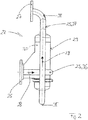
- Fig. 2 and 3 show a preferred embodiment of an ammonia generator 22, which, as already stated, at least the nozzle 23 and the hydrolysis catalyst 24 comprises, wherein the ammonia generator 22 in Fig. 2 and 3 is shown together with the bypass line 25.
- the gas flow is supplied to the ammonia generator 22 via the section of the bypass line 25 which cooperates with the flange 26, and then the gas flow with the ammonia can be directed toward the SCR catalytic converter 21 via the section of the bypass line 25 cooperating with the flange 27.
- Arrows 28 illustrate the gas flow through the bypass line 25 and the ammonia generator 22.
- the ammonia generator 22 of in Fig. 2 and 3 shown, preferred embodiment has a double-walled housing 29 with a radially outer housing wall 30 and a radially inner housing wall 31 which extend concentrically or coaxially to each other, wherein the double-walled housing 29 and the two housing walls 30 and 31, a radially inner flow channel 32 and define a radially outer flow channel 33.
- the radially inner flow channel 32 of the hydrolysis catalyst 24 is positioned, which has two catalyst stages 34 and 35 in the illustrated preferred embodiment.
- the radially inner flow channel 32, in which the hydrolysis catalyst 24 is positioned, is surrounded by the radially outer flow channel 33, the gas flow, in which the aqueous urea solution is to be introduced via the nozzle 23, the radially outer flow channel 33 via a tangential in the radial outer flow channel 33 opening gas supply line 36 can be introduced tangentially into the radially outer flow channel 33.
- This gas supply line 36 is that section of the bypass line 25 that runs upstream of the ammonia generator 22.
- the downstream of the ammonia generator 22 extending portion of the bypass line 25 may be referred to as Gasabloom protest 37.
- the gas flow entering into the radially outer flow passage 33 in the tangential direction is twisted by this flow guide in the region of the radially inner flow passage 33 and flows in Fig. 3 to the top, according to Fig. 3 the radially outer flow channel 33 above or adjacent to the nozzle 23 into the radially inner flow passage 32, so that in the region of the nozzle 23, which serves to introduce the aqueous urea solution into the gas flow 28, the gas flow 28 from the radially outer flow passage 33 in the radial inner flow channel 32 passes.
- a flow constriction means 38 is preferably further positioned, which reduces the cross section of the radially inner flow channel 32 so that the gas flow 28 is accelerated downstream of the nozzle 23 and so the urea solution on the Nozzle 23 is introduced into the accelerated gas flow 28.
- the flow constriction means 38 is preferably a diaphragm 38 narrowing the flow cross section of the radially inner flow channel 32.
- the hydrolysis catalyst 24 of the ammonia generator 22 of the preferred embodiment is designed in two stages, namely with a first upstream and relatively coarse-cell catalyst stage 34 seen in the flow direction of the radially inner flow channel 32, and a second downstream and downstream flow direction of the radially inner flow channel 32 relatively fine-cell catalyst stage 35.
- Such a two-stage hydrolysis catalyst 24 is preferred to assist in effective conversion of the aqueous urea solution to ammonia, carbon dioxide and water vapor.
- the flow direction in the radially outer flow channel 33 is opposite to the flow direction in the radially inner flow channel 32, wherein the gas flow in the outer flow channel 33 at least partially overlaps the radially inner flow channel 32 at least in the area of the first catalyst stage 34 of the hydrolysis catalytic converter 24, so that then at least the first catalyst stage 34 of the hydrolysis catalyst 24 can be tempered via the gas flow in the radially outer flow channel 33.
- the gas supply line 36 which opens tangentially into the outer flow channel 33, opens into a section of the outer flow channel 33 which covers the radially inner flow channel 32 in a region in which the hydrolysis catalytic converter 24 is positioned, namely in the exemplary embodiment shown Fig. 3
- the gas flow of the radially outer flow passage 33 completely covers the first catalyst stage 34 and the second catalyst stage 35 partially overlies the second catalyst stage 35 of the hydrolysis catalytic converter 24.
- a particularly advantageous tempering of the hydrolysis catalyst 24 in the region of its two catalyst stages 34 and 35 can be realized.
- a gas flow preferably a portion of the exhaust gas, upstream of the charging device 15 is removed and passed through the ammonia generator 22, said gas flow is fed tangentially to the radial outer flow channel 33 of the housing 29 of the ammonia generator 22.
- the gas flow is twisted.
- the twisted gas flow flows in a transition region, which is positioned adjacent to the nozzle 23, in the radially inner flow channel 32 of the ammonia generator 22, ie from radially outside to radially inside, wherein in the radially inner flow channel 32 of the hydrolysis 24 is positioned.
- An orifice 38 positioned upstream of the hydrolysis catalyst 24 and downstream of the nozzle 23 in the region of the radially inner flow channel 32 causes acceleration of the twisted gas flow in the region where the aqueous urea solution is introduced into the gas flow via the nozzle 23.
- the gas flow passes together with the aqueous urea solution in the region of the hydrolysis catalyst 24, wherein the hydrolysis catalyst 24 is uniformly supplied with the gas flow and the urea solution.
- the hydrolysis catalyst the conversion of urea solution into ammonia, carbon dioxide and water vapor takes place.
- the ammonia generator 22 is characterized by a high degree of effectiveness and compact design.
- the housing 29 is made in two parts from an upper part and a lower part, which are detachably connected via a band clamp 48.
- FIG. 4 Another example of a non-inventive ammonia generator 39 shows Fig. 4 ,
- the ammonia generator 39 of the Fig. 4 has a single-walled housing 40, which defines a flow channel 41, wherein in this flow channel 41 on the one hand a nozzle 42 for injecting the aqueous urea solution into the gas flow 43 and on the other hand seen in the flow direction downstream of the nozzle 42 of the hydrolysis 44 is arranged.
- the gas flow 43 is twisted prior to the injection of the aqueous urea solution into the same swirl-producing means 46 having a swirl slot 45, the swirl-generating means 46 having the swirl slots 45 surrounding the swirl slot 45 radially surrounding the nozzle 42 in the flow direction of the gas flow 43.
- a flow restriction 47 is positioned in the form of a diaphragm to accelerate the vorverdallte gas flow 43 and thus inject the aqueous urea solution into a twisted and accelerated gas flow 43.
- the urea solution to be reacted in ammonia in the region of the hydrolysis catalyst 44 can be uniformly introduced into the gas flow 43, and the hydrolysis catalyst 44 can be uniformly charged with the gas flow and the urea solution.
- the execution of Fig. 2 and 3 However, to ensure a compact design of the ammonia generator is preferred.
- the swirl in the gas flow is generated in each case over a large radius, that is to say in relation to a positioning of the nozzle 23, 42 radially on the outside. Then, when in contrast to the embodiments shown, the swirl in the gas flow is generated in each case on a small radius, the swirl generating means is seen in the flow direction of the gas flow between the nozzle and flow constriction means or diaphragm positioned.
- nozzles 23, 42 nozzles of different types can be used in the examples shown. Air-assisted pressure atomisers are preferably used as nozzles 23, 42.
Landscapes
- Chemical & Material Sciences (AREA)
- Engineering & Computer Science (AREA)
- Chemical Kinetics & Catalysis (AREA)
- Health & Medical Sciences (AREA)
- Toxicology (AREA)
- Combustion & Propulsion (AREA)
- Mechanical Engineering (AREA)
- General Engineering & Computer Science (AREA)
- Exhaust Gas After Treatment (AREA)
Description
- Hierzu ist zwischen einer Düse, welche die wässrige Harnstofflösung in das Abgas einbringt und welche in einer zwischen der Brennkraftmaschine und dem SCR-Katalysator verlaufenden Abgasleitung positioniert ist, und dem SCR-Katalysator, der das Ammoniak als Reduktionsmittel nutzt, eine Prozessstrecke mit zumindest einem Hydrolysekatalysator erforderlich. Düse und Hydrolysekatalysator bilden zusammen einen Ammoniakgenerator.
- Die Generierung von Ammoniak aus einer in das Abgas eingebrachten, wässrigen Harnstofflösung ist zum Beispiel aus der
DE 10 2009 035 692 A1 sowie aus derDE 10 2009 035 692 A1 bekannt. - Bei aus der Praxis bekannten Ammoniakgeneratoren bereitet eine gleichförmige Verteilung der Harnstofflösung in die über den Hydrolysekatalysator zu leitende Gasströmung Schwierigkeiten. Ferner ist es bei aus der Praxis bekannten Ammoniakgeneratoren nicht möglich, den Hydrolysekatalysator gleichförmig mit der Gasströmung, in welches die wässrige Harnstofflösung eingebracht wurde, zu beaufschlagen. Daher verfügen bekannte Ammoniakgeneratoren nur über eine begrenzte Effektivität.
- Die
EP 2 111 916 A1 zeigt bereits eine Vorrichtung zur Einspritzung eines Reduktionsmittels über eine Düse in die Abgase eines Dieselmotors, die ein Mischelement aufweist, welches stromaufwärts eines Hydrolysekatalysators und eines SCR-Katalysators zur Verdrallung der Abgase im Einspritzbereich führt. DieWO 2012/050509 zeigt ein Einspritzsystem für Harnstofflösungen für den Einsatz in Abgasreinigungseinrichtungen von Verbrennungsmotoren mit SCR-Katalysatoren aufweisend ein doppelwandiges Gehäuse, welches einen radial inneren Strömungskanal, einen radial äußeren Strömungskanal, welchem der Gasstrom über einen ringförmigen Einlass zugeführt wird, wobei der radial äußere Strömungskanal benachbart einer Einspritzdüse in den radial inneren Strömungskanal übergeht. - Hiervon ausgehend liegt bei vorliegender Erfindung die technische Aufgabe zugrunde, dass ein Amoniakgenerator bestehend aus einer Einspritzdüse für das Reduktionsmittel und einem Hydrolysekatalysator mit verbesserter Wärmeeffizienz bereitgestellt wird.
- Diese Aufgabe wird durch einen Ammoniakgenerator nach Anspruch 1 gelöst.
- Der erfindungsgemäße Ammoniakgenerator umfasst zumindest ein Drallerzeugungsmittel zur Verdrallung der Gasströmung, in welche die Harnstofflösung einbringbar ist.
- Hierzu ist zwischen einer Düse, welche die wässrige Harnstofflösung in das Abgas einbringt und welche in einer zwischen der Brennkraftmaschine und dem SCR-Katalysator verlaufenden Abgasleitung positioniert ist, und dem SCR-Katalysator, der das Ammoniak als Reduktionsmittel nutzt, eine Prozessstrecke mit zumindest einem Hydrolysekatalysator erforderlich. Düse und Hydrolysekatalysator bilden zusammen einen Ammoniakgenerator.
- Die Generierung von Ammoniak aus einer in das Abgas eingebrachten, wässrigen Harnstofflösung ist zum Beispiel aus der
DE 10 2009 035 692 A1 sowie aus derDE 10 2009 035 692 A1 bekannt. - Bei aus der Praxis bekannten Ammoniakgeneratoren bereitet eine gleichförmige Verteilung der Harnstofflösung in die über den Hydrolysekatalysator zu leitende Gasströmung Schwierigkeiten. Ferner ist es bei aus der Praxis bekannten Ammoniakgeneratoren nicht möglich, den Hydrolysekatalysator gleichförmig mit der Gasströmung, in welches die wässrige Harnstofflösung eingebracht wurde, zu beaufschlagen. Daher verfügen bekannte Ammoniakgeneratoren nur über eine begrenzte Effektivität.
- Hiervon ausgehend liegt der vorliegenden Erfindung die Aufgabe zugrunde, einen neuartigen Ammoniakgenerator zu schaffen.
- Diese Aufgabe wird durch einen Ammoniakgenerator nach Anspruch 1 gelöst.
- Der erfindungsgemäße Ammoniakgenerator umfasst zumindest ein Drallerzeugungsmittel zur Verdrallung der Gasströmung, in welche die Harnstofflösung einbringbar ist.
- Das Drallerzeugungsmittel des erfindungsgemäßen Ammoniakgenerators ermöglicht es auf einfache und sichere Art und Weise, die wässrige Harnstofflösung gleichförmig in die Gasströmung einzubringen. Ferner ist es möglich, den Hydrolysekatalysator mit der Gasströmung, in welche die Harnstofflösung gleichförmig eingebracht wurde, gleichförmig zu beaufschlagen. Daher weist der erfindungsgemäße Ammoniakgenerator eine hohe Effektivität auf. Dann, wenn das Drallerzeugungsmittel die Gasströmung vor dem Einbringen der Harnstofflösung in die Gasströmung verdrallt, kann die wässrige Harnstofflösung besonders gleichförmig in die Gasströmung eingebracht werden.
- Vorzugsweise umfasst der erfindungsgemäße Ammoniakgenerator weiterhin ein Strömungsverengungsmittel zur Beschleunigung der Gasströmung, in welche die Harnstofflösung einbringbar ist, nämlich zur Strömungsverengung der Gasströmung stromabwärts der Düse. Das Strömungsverengungsmittel des erfindungsgemäßen Ammoniakgenerators unterstützt einerseits das gleichförmige Einbringen der wässrigen Harnstofflösung in die Gasströmung und andererseits die gleichförmige Beaufschlagung des Hydrolysekatalysators mit der Gasströmung, in welche die Harnstofflösung eingebracht wurde. Dadurch kann die Effektivität des Ammoniakgenerators weiter gesteigert werden. Der Ammoniakgenerator weist ein doppelwandiges Gehäuse auf, welches einen radial inneren Strömungskanal, in welchem der Hydrolysekatalysator positioniert ist, und einen radial äußeren Strömungskanal, welchem die Gasströmung zur Verdrallung derselben tangential zuführbar ist, definiert, wobei der radial äußere Strömungskanal im Bereich der Düse in den radial inneren Strömungskanal übergeht. Vorzugsweise bildet der radial äußere Strömungskanal zusammen mit einer tangential in denselben mündenden Gasleitung das Drallerzeugungsmittel, wobei das vorzugsweise vorhandene Strömungsverengungsmittel im Übergangsbereich zwischen dem radial äußeren Strömungskanal und dem radial inneren Strömungskanal stromabwärts der Düse positioniert ist.
- Dies erlaubt es mit einfachen Mitteln unter Gewährleistung einer kompakten Bauform des Ammoniakgenerators die Gasströmung, in welche die Harnstofflösung einzubringen ist, vor dem Einbringen der Harnstofflösung zu verdrallen. In Kombination mit der Strömungsverengung stromabwärts der Düse, über welche die Harnstofflösung in die verdrallte Gasströmung eingebracht wird, können so die oben genannten erfindungsgemäßen Vorteile auf engstem Bauraum realisiert werden. Der Hydrolysekatalysator weist eine erste, in Strömungsrichtung des radial inneren Strömungskanals gesehen stromaufwärige und relativ grobzellige Katalysatorstufe und eine zweite, in Strömungsrichtung des radial inneren Strömungskanals gesehen stromabwärtige und relativ feinzellige Katalysatorstufe auf, wobei die Strömungsrichtung des radial äußeren Strömungskanals entgegengesetzt zur Strömungsrichtung des radial inneren Strömungskanals verläuft, und wobei die Gasströmung des äußeren Strömungskanals den radial innen Strömungskanal zumindest im Bereich der ersten Katalysatorstufe zumindest abschnittsweist überstreift. Die tangential in den äußeren Strömungskanal mündende Gasleitung mündet vorzugsweise in einen Abschnitt des äußeren Strömungskanals, der den im radial inneren Strömungskanal positionierten Hydrolysekatalysator abschnittsweise überdeckt. Hierdurch ist es möglich, den Hydrolysekatalysator über die Strömung im radial äußeren Strömungskanal auf eine definierte Temperatur zu bringen und so die Effektivität des erfindungsgemäßen Ammoniakgenerators weiter zu steigern.
- Bevorzugte Weiterbildungen der Erfindung ergeben sich aus den Unteransprüchen und der nachfolgenden Beschreibung. Ausführungsbeispiele der Erfindung werden, ohne hierauf beschränkt zu sein, an Hand der Zeichnung näher erläutert. Dabei zeigt:
- Fig. 1:
- eine schematische Darstellung einer Brennkraftmaschine;
- Fig. 2:
- einen erfindungsgemäßen Ammoniakgenerator von außen;
- Fig. 3:
- den Querschnitt III-III der
Fig. 2 durch den erfindungsgemäßen Ammoniakgenerator; und - Fig. 4:
- einen Querschnitt durch einen weiteren nicht erfindungsgemäßen Ammoniakgenerator.
-
Fig. 1 zeigt eine stark schematisierte Ansicht einer Brennkraftmaschine 10, bei welcher es sich vorzugsweise um eine mit Schweröl betriebene Schiffsdieselbrennkraftmaschine handelt. Es sei an dieser Stelle darauf hingewiesen, dass die Konfiguration der Brennkraftmaschine 10 derFig. 1 exemplarischer Natur ist und die Erfindung nicht auf diese Brennkraftmaschinenkonfiguration beschränkt ist. - Die in
Fig. 1 gezeigte Brennkraftmaschine 10 verfügt über einen Motor 11 mit mehreren Zylindern 12, wobei gemäßFig. 1 den Zylindern 11 zur Verbrennung von Kraftstoff Ladeluft 13 zugeführt wird, und wobei bei der Verbrennung des Kraftstoffs in den Zylindern 11 entstehendes Abgas 14 von den Zylindern 12 abgeführt werden kann. - Die Brennkraftmaschine 10 der
Fig. 1 verfügt über eine Aufladungsvorrichtung 15, die im gezeigten Ausführungsbeispiel zweistufig mit einem Niederdruckturbolader 16a und einem Hochdruckturbolader 16b ausgeführt ist. - Ladeluft 13, die den Zylindern 12 des Motors 11 der Brennkraftmaschine 10 zugeführt wird, wird zunächst in einem Niederdruckverdichter 18a des Niederdruckturboladers 16a und anschließend in einem Hochdruckverdichter 18b des Hochdruckturboladers 16b verdichtet, wobei hierzu benötigte Energie durch das Entspannen des Abgases 14 einerseits in der Hochdruckturbine 17b des Hochdruckturboladers 16b und andererseits in der Niederdruckturbine 17a des Niederdruckturboladers 16a gewonnen wird.
- Das Abgas 14, welches die Zylinder 12 des Motors 11 verlässt, gelangt zunächst in den Bereich der Hochdruckturbine 17b des Hochdruckturboladers 16b, wobei in der Hochdruckturbine 17b des Hochdruckturboladers 16b bei den Entspannung des Abgases 14 gewonnene Energie genutzt wird, um den Hochdruckverdichter 18b des Hochdruckturboladers 16b anzutreiben. Anschließend gelangt das Abgas in den Bereich der Niederdruckturbine 17a des Niederdruckturboladers 16a, wobei in der Niederdruckturbine 17a gewonnene Energie genutzt wird, um den Niederdruckverdichter 18a des Niederdruckturboladers 16a anzutreiben. Gemäß
Fig. 1 ist sowohl stromabwärts des Niederdruckverdichters 18a als auch stromabwärts des Hochdruckverdichters 18b jeweils ein Ladeluftkühler 19a bzw. 19b positioniert, um die Ladeluft 13 zu kühlen. - Gemäß
Fig. 1 umfasst die Brennkraftmaschine 10 weiterhin eine Abgasreinigungsvorrichtung 20, die zumindest einen SCR-Katalysator 21 umfasst. - Im SCR-Katalysator 21 der Abgasreinigungsvorrichtung 20 wird als Reduktionsmittel Ammoniak genutzt, wobei das Ammoniak von einem Ammoniakgenerator 22 bereitgestellt wird. Der Ammoniakgenerator 22 verfügt über eine Düse 23, um in eine Gasströmung eine wässrige Harnstofflösung einzubringen, wobei der Düse 23 des Ammoniakgenerators 22 ein Hydrolysekatalysator 24 des Ammoniakgenerators 22 nachgelagert ist, in welchem die wässrige Harnstofflösung zu Ammoniak, Kohlendioxid und Wasserdampf zersetzt wird.
- Im Ausführungsbeispiel der
Fig. 1 handelt es sich bei der Gasströmung, die über den Ammoniakgenerator 22 geleitet wird, um Abgas, welches in Strömungsrichtung des Abgases 14 gesehen stromaufwärts der Aufladungsvorrichtung 15, nämlich stromaufwärts der Hochdruckturbine 17b, über eine Bypassleitung 25 und ein nicht gezeigtes Wastegateventil vom Abgas 14 abgezweigt wird, und welches stromabwärts der Aufladungsvorrichtung 15, nämlich gemäßFig. 1 stromabwärts der Niederdruckturbine 17a, und stromaufwärts des SCR-Katalysators 21 wieder in das Abgas eingeleitet wird. - Obwohl das Einbringen der wässrigen Harnstofflösung in eine vom Abgas 14 über die Bypassleitung 25 abgezweigten Abgasteilströmung bevorzugt ist, ist es im Unterschied hierzu auch möglich, stromabwärts des Hochdruckverdichters 18b und stromaufwärts des Ladeluftkühlers 19b verdichtete Ladeluft abzuzweigen und dieselbe über den Ammoniakgenerator 22 zu führen, um dann die wässrige Harnstofflösung über die Düse 23 in einen Teil der Ladeluft einzubringen und demnach als Gasströmung nicht Abgas sondern Ladeluft über den Ammoniakgenerator 22 zu führen. Unter dem Begriff Gasströmung kann demnach einerseits eine Abgasteilströmung und andererseits eine Ladeluftteilströmung verstanden werden, die über den Ammoniakgenerator 22 geführt werden kann.
- Die hier vorliegende Erfindung betrifft Details des Ammoniakgenerators 22, mit Hilfe dessen effektiv die Harnstofflösung in Ammoniak, Kohlendioxid und Wasserdampf umgesetzt werden kann.
- Der erfindungsgemäße Ammoniakgenerator 22 verfügt zumindest über ein Drallerzeugungsmittel und vorzugsweise weiterhin über ein Strömungsverengungsmittel. Über das Drallerzeugungsmittel wird die Gasströmung, in welche die Harnstofflösung eingebracht wird, verdrallt, vorzugsweise vor dem Einbringen der Harnstofflösung in die Gasströmung. Über das vorzugsweise vorhandene Strömungsverengungsmittel ist die Gasströmung hinsichtlich ihres Strömungsquerschnitts einschnürbar und damit beschleunigbar, nämlich stromabwärts der Düse 23. Wie bereits ausgeführt, kann es sich bei der Gasströmung um einen vom Abgas oder von der Ladeluft abgezweigten Teilstrom handeln. In jedem Fall ist es möglich, infolge der Verdrallung der Gasströmung und der vorzugweise in Kombination genutzten Verengung bzw. Beschleunigung der Gasströmung einerseits die Harnstofflösung effektiv und gleichförmig in der Gasströmung zu verteilen und andererseits den Hydrolysekatalysator 24 gleichförmig mit der Gasströmung und der in die Gasströmung eingebrachten Harnstofflösung zu beaufschlagen, um so eine effektive Umsetzung der Harnstofflösung in Ammoniak, Kohlendioxid und Wasserdampf zu gewährleisten.
-
Fig. 2 und3 zeigen ein bevorzugtes Ausführungsbeispiel eines Ammoniakgenerators 22, der, wie bereits ausgeführt, zumindest die Düse 23 und den Hydrolysekatalysator 24 umfasst, wobei der Ammoniakgenerator 22 inFig. 2 und3 zusammen mit der Bypassleitung 25 gezeigt ist. Über den mit dem Flansch 26 zusammenwirkenden Abschnitt der Bypassleitung 25 wird die Gasströmung dem Ammoniakgenerator 22 zugeführt, über den mit dem Flansch 27 zusammenwirkenden Abschnitt der Bypassleitung 25 kann anschließend die Gasströmung mit dem Ammoniak in Richtung auf den SCR-Katalysator 21 geleitet werden. Pfeile 28 verdeutlichen die Gasströmung durch die Bypassleitung 25 und den Ammoniakgenerator 22. - Der Ammoniakgenerator 22 des in
Fig. 2 und3 gezeigten, bevorzugten Ausführungsbeispiels verfügt über ein doppelwandiges Gehäuse 29 mit einer radial äußeren Gehäusewand 30 und einer radial inneren Gehäusewand 31, die konzentrisch bzw. koaxial zueinander verlaufen, wobei das doppelwandige Gehäuse 29 bzw. die beiden Gehäusewände 30 und 31 einen radial inneren Strömungskanal 32 und einen radial äußeren Strömungskanal 33 definieren. - In dem radial inneren Strömungskanal 32 ist der Hydrolysekatalysator 24 positioniert, der im gezeigten, bevorzugten Ausführungsbeispiel zwei Katalysatorstufen 34 und 35 aufweist. Der radial innere Strömungskanal 32, in welchem der Hydrolysekatalysator 24 positioniert ist, ist vom radial äußeren Strömungskanal 33 umgeben, wobei die Gasströmung, in welche die wässrige Harnstofflösung über die Düse 23 eingebracht werden soll, dem radial äußeren Strömungskanal 33 über eine tangential in den radial äußeren Strömungskanal 33 mündende Gaszuführleitung 36 in den radial äußeren Strömungskanal 33 tangential eingebracht werden kann. Bei dieser Gaszuführleitung 36 handelt es sich um denjenigen Abschnitt der Bypassleitung 25, der stromaufwärts des Ammoniakgenerators 22 verläuft. Der stromabwärts des Ammoniakgenerators 22 verlaufende Abschnitt der Bypassleitung 25 kann als Gasabführleitung 37 bezeichnet werden.
- Die in tangentialer Richtung in den radial äußeren Strömungskanal 33 eintretende Gasströmung wird durch diese Strömungsführung im Bereich des radial inneren Strömungskanals 33 verdrallt und strömt in
Fig. 3 nach oben, wobei gemäßFig. 3 der radial äußere Strömungskanal 33 oben bzw. benachbart zur Düse 23 in den radial inneren Strömungskanal 32 übergeht, sodass im Bereich der Düse 23, die dem Einbringen der wässrigen Harnstofflösung in die Gasströmung 28 dient, die Gasströmung 28 vom radial äußeren Strömungskanal 33 in den radial inneren Strömungskanal 32 übertritt. - In diesem Übergangsbereich zwischen dem radial äußeren Strömungskanal 33 und dem radial inneren Strömungskanal 32 ist vorzugsweise ferner ein Strömungsverengungsmittel 38 positioniert, welches den Querschnitt des radial inneren Strömungskanals 32 derart reduziert, dass stromabwärts der Düse 23 die Gasströmung 28 beschleunigt wird und so die Harnstofflösung über die Düse 23 in die beschleunigte Gasströmung 28 eingebracht wird.
- Bei dem Strömungsverengungsmittel 38 handelt es sich vorzugsweise um eine den Strömungsquerschnitt des radial inneren Strömungskanals 32 verengende Blende 38.
- Wie bereits ausgeführt, ist der Hydrolysekatalysator 24 des Ammoniakgenerators 22 des bevorzugten Ausführungsbeispiels zweistufig ausgeführt, nämlich mit einer ersten, in Strömungsrichtung des radial inneren Strömungskanals 32 gesehen stromaufwärtigen und relativ grobzelligen Katalysatorstufe 34 und einer zweiten, in Strömungsrichtung des radial inneren Strömungskanals 32 gesehen stromabwärtigen und relativ feinzelligen Katalysatorstufe 35.
- Ein derart zweistufiger Hydrolysekatalysator 24 ist bevorzugt, um eine effektive Umsetzung der wässrigen Harnstofflösung in Ammoniak, Kohlendioxid und Wasserdampf zu unterstützen.
- Eine weitere Besonderheit des erfindungsgemäßen Ammoniakgenerators 22 der
Fig. 2 und3 besteht darin, dass die Strömungsrichtung im radial äußeren Strömungskanal 33 entgegengesetzt zur Strömungsrichtung im radial inneren Strömungskanal 32 verläuft, wobei die Gasströmung im äußeren Strömungskanal 33 den radial inneren Strömungskanal 32 zumindest im Bereich der ersten Katalysatorstufe 34 des Hydrolysekatalysators 24 zumindest abschnittsweise überstreift, sodass dann zumindest die erste Katalysatorstufe 34 des Hydrolysekatalysators 24 über die Gasströmung im radial äußeren Strömungskanal 33 temperiert werden kann. - Im gezeigten, bevorzugten Ausführungsbeispiel mündet die tangential in den äußeren Strömungskanal 33 mündende Gaszuführleitung 36 in einen Abschnitt des äußeren Strömungskanals 33, der den radial inneren Strömungskanal 32 in einem Bereich überdeckt, in welchem der Hydrolysekatalysator 24 positioniert ist, nämlich im gezeigten Ausführungsbeispiel gemäß
Fig. 3 die zweite Katalysatorstufe 35 des Hydrolysekatalysators 24. Demzufolge überstreift die Gasströmung des radial äußeren Strömungskanals 33 die erste Katalysatorstufe 34 vollständig und die zweite Katalysatorstufe 35 teilweise. Hiermit kann eine besonders vorteilhafte Temperierung des Hydrolysekatalysators 24 im Bereich seiner beiden Katalysatorstufen 34 und 35 realisiert werden. - Im Ausführungsbeispiel der
Fig. 2 und3 wird demnach eine Gasströmung, vorzugsweise ein Teil des Abgases, stromaufwärts der Aufladungseinrichtung 15 entnommen und über den Ammoniakgenerator 22 geleitet, wobei diese Gasströmung dem radialen äußeren Strömungskanal 33 des Gehäuses 29 des Ammoniakgenerators 22 tangential zugeführt wird. Hierbei wird die Gasströmung verdrallt. - Die verdrallte Gasströmung strömt in einem Übergangsbereich, der benachbart zur Düse 23 positioniert ist, in den radial inneren Strömungskanal 32 des Ammoniakgenerators 22 über, also von radial außen nach radial innen, wobei im radial inneren Strömungskanal 32 der Hydrolysekatalysator 24 positioniert ist.
- Eine stromaufwärts des Hydrolysekatalysators 24 und stromabwärts der Düse 23 im Bereich des radial inneren Strömungskanals 32 positionierte Blende bzw. Verengungsmittel 38 bewirkt eine Beschleunigung der verdrallten Gasströmung in dem Bereich, in welchem über die Düse 23 die wässrige Harnstofflösung in die Gasströmung eingebracht wird.
- Anschließend gelangt die Gasströmung zusammen mit der wässrigen Harnstofflösung in den Bereich des Hydrolysekatalysators 24, wobei der Hydrolysekatalysator 24 gleichförmig mit der Gasströmung und der Harnstofflösung beaufschlagt wird. Im Hydrolysekatalysator erfolgt die Umsetzung von Harnstofflösung in Ammoniak, Kohlendioxid und Wasserdampf. Der Ammoniakgenerator 22 zeichnet sich durch eine hohe Effektivität und kompakte Bauform aus.
- Um einen einfachen Austausch des Hydrolysekatalysators 24 zu ermöglichen, ist das Gehäuse 29 zweiteilig aus einem Oberteil und einem Unterteil ausgeführt, die über eine Bandschelle 48 lösbar verbunden sind.
- Ein weiteres Beispiel eines nicht erfindungsgemäßen Ammoniakgenerators 39 zeigt
Fig. 4 . Der Ammoniakgenerator 39 derFig. 4 verfügt über ein einwandiges Gehäuse 40, welches einen Strömungskanal 41 definiert, wobei in diesem Strömungskanal 41 einerseits eine Düse 42 zum Einspritzen der wässrigen Harnstofflösung in die Gasströmung 43 und andererseits in Strömungsrichtung gesehen stromabwärts der Düse 42 der Hydrolysekatalysator 44 angeordnet ist. InFig. 4 erfolgt die Verdrallung der Gasströmung 43 vor dem Einspritzen der wässrigen Harnstofflösung in dieselbe über ein Drallschlitze 45 aufweisendes Drallerzeugungsmittel 46, wobei das die Drallschlitze 45 aufweisende Drallerzeugungsmittel 46 in Strömungsrichtung der Gasströmung 43 gesehen die Düse 42 radial außen umgibt. Auch hiermit wird die Gasströmung 43 vor dem Einbringen der Harnstofflösung in dieselbe verdrallt, wobei gemäßFig. 4 in Strömungsrichtung der Gasströmung 43 gesehen stromabwärts der Düse 42 und stromaufwärts des Hydrolysekatalysators 44 ein Strömungsverengungsmittel 47 in Form einer Blende positioniert ist, um die vorab verdrallte Gasströmung 43 zu beschleunigen und so die wässrige Harnstofflösung in eine verdrallte und beschleunigte Gasströmung 43 einzuspritzen. - Auch in
Fig. 4 kann die im Bereich des Hydrolysekatalysators 44 in Ammoniak umzusetzende Harnstofflösung gleichförmig in die Gasströmung 43 eingebracht und der Hydrolysekatalysator 44 gleichförmig mit der Gasströmung und der Harnstofflösung beaufschlagt werden. Die Ausführung derFig. 2 und3 ist jedoch zur Gewährleistung einer kompakten Bauform des Ammoniakgenerators bevorzugt. - In den beiden gezeigten Beispielen wird der Drall in der Gasströmung jeweils auf großem Radius erzeugt, also bezogen auf eine Positionierung der Düse 23, 42 radial außen. Dann, wenn im Unterscheid zu den gezeigten Ausführungsbeispielen der Drall in der Gasströmung jeweils auf kleinem Radius erzeugt wird, ist das Drallerzeugungsmittel in Strömungsrichtung der Gasströmung gesehen zwischen Düse und Strömungsverengungsmittel bzw. Blende positioniert.
- Als Düsen 23, 42 können in den gezeigten Beispielen Düsen verschiedener Bauart genutzt werden. Vorzugsweise werden luftunterstützte Druckzerstäuber als Düsen 23, 42 verwendet.
-
- 10
- Brennkraftmaschine
- 11
- Motor
- 12
- Zylinder
- 13
- Ladeluft
- 14
- Abgas
- 15
- Aufladungsvorrichtung
- 16a
- Niederdruckturbolader
- 16b
- Hochdruckturbolader
- 17a
- Niederdruckturbine
- 17b
- Hochdruckturbine
- 18a
- Niederdruckverdichter
- 18b
- Hochdruckverdichter
- 19a
- Ladeluftkühler
- 19b
- Ladeluftkühler
- 20
- Abgasreinigungsvorrichtung
- 21
- SCR-Katalysator
- 22
- Ammoniakgenerator
- 23
- Düse
- 24
- Hydrolysekatalysator
- 25
- Bypassleitung
- 26
- Flansch
- 27
- Flansch
- 28
- Strömungsrichtung
- 29
- Gehäuse
- 30
- Gehäusewand
- 31
- Gehäusewand
- 32
- radial innerer Strömungskanal
- 33
- radial äußerer Strömungskanal
- 34
- Katalysatorstufe
- 35
- Katalysatorstufe
- 36
- Gaszuführleitung
- 37
- Gasabführleitung
- 38
- Strömungsverengungsmittel / Blende
- 39
- Ammoniakgenerator
- 40
- Gehäuse
- 41
- Strömungskanal
- 42
- Düse
- 43
- Gasströmung
- 44
- Hydrolysekatalysator
- 45
- Drallschlitze
- 46
- Drallerzeugungsmittel
- 47
- Strömungsverengungsmittel / Blende
- 48
- Bandschelle
Claims (8)
- Ammoniakgenerator für eine Abgasreinigungsvorrichtung einer Brennkraftmaschine, nämlich zur Erzeugung von als Reduktionsmittel für einen SCR-Katalysator der Abgasreinigungsvorrichtung dienendem Ammoniak aus einer Harnstofflösung, mit einer Düse (23; 42), über die in eine Gasströmung die Harnstofflösung einbringbar ist, und mit einem der Düse nachgeschalteten Hydrolysekatalysator (24; 44), über den das in die Gasströmung eingebrachte Harnstofflösung zu Wasserdampf und Kohlendioxid und Ammoniak zersetzbar ist, und ein Drallerzeugungsmittel (33, 36; 46) zur Verdrallung der Gasströmung vorgesehen ist, in welche die Harnstofflösung einbringbar ist, wobei der Ammoniakgenerator ein doppelwandiges Gehäuse (29) aufweist, welches einen radial inneren Strömungskanal (32), in welchem der Hydrolysekatalysator (24) positioniert ist, und einen radial äußeren Strömungskanal (33), welchem die Gasströmung zur Verdrallung derselben tangential zuführbar ist, definiert, wobei der radial äußere Strömungskanal (33) benachbart Düse (23) in den radial inneren Strömungskanal (32) übergeht, dadurch gekennzeichnet dass der Hydrolysekatalysator (24) eine erste, in Strömungsrichtung des radial inneren Strömungskanals (32) gesehen stromaufwärtige und relativ grobzellige Katalysatorstufe (34) und eine zweite, in Strömungsrichtung des radial inneren Strömungskanals (32) gesehen stromabwärtige und relativ feinzellige Katalysatorstufe (35) aufweist, wobei die Strömungsrichtung des radial äußeren Strömungskanals (33) entgegengesetzt zur Strömungsrichtung des radial inneren Strömungskanals (32) verläuft, und wobei die Gasströmung des äußeren Strömungskanals (33) den radial inneren Strömungskanal (32) zumindest im Bereich der ersten Katalysatorstufe (34) zumindest abschnittsweise überstreift, und dass die tangential in den äußeren Strömungskanal (33) mündende Gaszuführleitung (36) in einen Abschnitt des äußeren Strömungskanals (33) mündet, der den im radial inneren Strömungskanal (32) positionierten Hydrolysekatalysator (24) abschnittsweise.
- Ammoniakgenerator nach Anspruch 1, dadurch gekennzeichnet, dass die Gasströmung des äußeren Strömungskanals (33) den radial inneren Strömungskanal (32) im Bereich der ersten Katalysatorstufe (34) vollständig und im Bereich der zweiten Katalysatorstufe (35) zumindest abschnittsweist überstreift.
- Ammoniakgenerator nach Anspruch 1, dadurch gekennzeichnet, dass das Drallerzeugungsmittel (33, 36; 46) die Gasströmung vor dem Einbringen der Harnstofflösung in die Gasströmung verdrallt.
- Ammoniakgenerator nach Anspruch 1 oder 2, gekennzeichnet durch ein Strömungsverengungsmittel (38; 47) zur Beschleunigung der Gasströmung, in welche die Harnstofflösung einbringbar ist, nämlich zur Strömungsverengung der Gasströmung stromabwärts der Düse (23; 42).
- Ammoniakgenerator nach Anspruch 1, dadurch gekennzeichnet, dass der radial äußere Strömungskanal (33) des doppelwandigen Gehäuses (29) zusammen mit einer tangential in denselben mündenden Gaszuführleitung (36) das Drallerzeugungsmittel (33, 36) bildet.
- Ammoniakgenerator nach einem der Ansprüche 3 bis 4, dadurch gekennzeichnet, dass das Strömungsverengungsmittel (38) im Übergangsbereich zwischen dem radial äußeren Strömungskanal (33) des doppelwandigen Gehäuses (29) und dem radial inneren Strömungskanal (32) des doppelwandigen Gehäuses (29) positioniert ist.
- Ammoniakgenerator nach einem der Ansprüche 3 bis 5, dadurch gekennzeichnet, dass das Strömungsverengungsmittel (38) von einer einen Strömungsquerschnitt des radial inneren Strömungskanals (32) verengenden Blende (38) gebildet ist.
- Brennkraftmaschine, nämlich mit Schweröl betriebene Brennkraftmaschine, mit einem mehrere Zylinder (12) aufweisenden Motor (11), mit einer mindestens einen Turbolader (16a, 16b) aufweisenden Aufladungsvorrichtung (15), mit einer einen SCR-Katalysator (21) aufweisenden Abgasreinigungsvorrichtung (20), und mit einem Ammoniakgenerator (22, 39) zur Erzeugung von als Reduktionsmittel für den SCR-Katalysator (21) dienendem Ammoniak aus einer Harnstofflösung, dadurch gekennzeichnet, dass der Ammoniakgenerator (22, 39) nach einem der Ansprüche 1 bis 7 ausgebildet ist.
Applications Claiming Priority (2)
| Application Number | Priority Date | Filing Date | Title |
|---|---|---|---|
| DE102013009417.8A DE102013009417A1 (de) | 2013-06-05 | 2013-06-05 | Ammoniakgenerator |
| PCT/EP2014/061661 WO2014195393A1 (de) | 2013-06-05 | 2014-06-05 | Ammoniakgenerator |
Publications (2)
| Publication Number | Publication Date |
|---|---|
| EP3004582A1 EP3004582A1 (de) | 2016-04-13 |
| EP3004582B1 true EP3004582B1 (de) | 2017-08-16 |
Family
ID=50942671
Family Applications (1)
| Application Number | Title | Priority Date | Filing Date |
|---|---|---|---|
| EP14730119.6A Not-in-force EP3004582B1 (de) | 2013-06-05 | 2014-06-05 | Ammoniakgenerator |
Country Status (5)
| Country | Link |
|---|---|
| EP (1) | EP3004582B1 (de) |
| KR (1) | KR101780141B1 (de) |
| CN (1) | CN105247185A (de) |
| DE (1) | DE102013009417A1 (de) |
| WO (1) | WO2014195393A1 (de) |
Families Citing this family (2)
| Publication number | Priority date | Publication date | Assignee | Title |
|---|---|---|---|---|
| DE102014222698B4 (de) | 2014-11-06 | 2017-12-14 | Eberspächer Exhaust Technology GmbH & Co. KG | Abgasnachbehandlungseinrichtung mit Injektionsabschnitt |
| CN113155668A (zh) * | 2021-04-21 | 2021-07-23 | 西安热工研究院有限公司 | 一种尿素水解产物测量系统及方法 |
Family Cites Families (18)
| Publication number | Priority date | Publication date | Assignee | Title |
|---|---|---|---|---|
| DE4203807A1 (de) * | 1990-11-29 | 1993-08-12 | Man Nutzfahrzeuge Ag | Vorrichtung zur katalytischen no(pfeil abwaerts)x(pfeil abwaerts)-reduktion |
| DE19731865C2 (de) * | 1997-07-24 | 1999-05-06 | Siemens Ag | Abgasreinigungsanlage für das Abgas eines Dieselmotors |
| ATE337076T1 (de) * | 1999-04-30 | 2006-09-15 | Argillon Gmbh | Verfahren zum einbringen eines reduktionsmittels eines stickoxids in ein gasgemisch und vorrichtung zum durchführen des verfahrens |
| DE10060808B4 (de) * | 2000-12-07 | 2004-12-02 | Robert Bosch Gmbh | Abgasreinigungsanlage |
| GB2381218B (en) * | 2001-10-25 | 2004-12-15 | Eminox Ltd | Gas treatment apparatus |
| JP2005344597A (ja) * | 2004-06-02 | 2005-12-15 | Hitachi Ltd | エンジン用排気ガス処理装置 |
| DE102004027593A1 (de) | 2004-06-05 | 2005-12-29 | Man B & W Diesel Ag | Motorenanlage mit Abgasturboaufladung und Betrieb eines SCR-Katalysators |
| EP2111916B1 (de) * | 2008-04-21 | 2012-10-24 | Swenox AB | Abgasbehandlungsvorrichtung, damit ausgestattetes Fahrzeug und Verfahren zur Abgasbehandlung |
| JP5456279B2 (ja) * | 2008-07-08 | 2014-03-26 | 三菱ふそうトラック・バス株式会社 | 内燃機関の排気浄化システム |
| CN102159810B (zh) * | 2008-09-19 | 2013-11-13 | 雷诺卡车公司 | 排气管中的混合装置 |
| DE102008048796A1 (de) * | 2008-09-24 | 2010-03-25 | Emitec Gesellschaft Für Emissionstechnologie Mbh | Abgasreinigungssystem für Dieselmotoren |
| DE102009035692A1 (de) | 2009-07-30 | 2011-02-03 | Man Nutzfahrzeuge Ag | Verfahren und Vorrichtung zur Reinigung eines Abgasstroms einer abgasaufgeladenen Brennkraftmaschine |
| DE102009041345A1 (de) * | 2009-09-15 | 2011-04-21 | Mtu Friedrichshafen Gmbh | System zur Einbringung eines fluiden Zusatzstoffes |
| DE102009053950A1 (de) * | 2009-11-19 | 2011-05-26 | Man Nutzfahrzeuge Aktiengesellschaft | Vorrichtung zur Nachbehandlung von Abgasen von Brennkraftmaschinen |
| DE102010045751B4 (de) * | 2010-09-17 | 2017-02-16 | Friedrich Boysen Gmbh & Co. Kg | Abgasanlage einer Brennkraftmaschine |
| SE535220C2 (sv) * | 2010-10-14 | 2012-05-29 | Scania Cv Abp | Arrangemang för att införa ett vätskeformigt medium i avgaser från en förbränningsmotor |
| DE102010056314A1 (de) * | 2010-12-27 | 2012-06-28 | Friedrich Boysen Gmbh & Co. Kg | Vorrichtung zum Verteilen von Fluiden in Abgasanlagen |
| DE102011118049A1 (de) * | 2011-11-05 | 2013-05-08 | Audi Ag | Abgasreinigungseinrichtung |
-
2013
- 2013-06-05 DE DE102013009417.8A patent/DE102013009417A1/de not_active Withdrawn
-
2014
- 2014-06-05 EP EP14730119.6A patent/EP3004582B1/de not_active Not-in-force
- 2014-06-05 KR KR1020157036760A patent/KR101780141B1/ko not_active Expired - Fee Related
- 2014-06-05 WO PCT/EP2014/061661 patent/WO2014195393A1/de not_active Ceased
- 2014-06-05 CN CN201480032171.0A patent/CN105247185A/zh active Pending
Non-Patent Citations (1)
| Title |
|---|
| None * |
Also Published As
| Publication number | Publication date |
|---|---|
| WO2014195393A1 (de) | 2014-12-11 |
| DE102013009417A1 (de) | 2014-12-11 |
| EP3004582A1 (de) | 2016-04-13 |
| CN105247185A (zh) | 2016-01-13 |
| KR20160014019A (ko) | 2016-02-05 |
| KR101780141B1 (ko) | 2017-09-19 |
Similar Documents
| Publication | Publication Date | Title |
|---|---|---|
| DE112008001962B4 (de) | Baugruppe und Verfahren zur Einbringung eines Reduktionsmittels in die Abgasleitung einer Abgasanlage einer Verbrennungskraftmaschine | |
| EP0852512B1 (de) | Verfahren und einrichtung zum abbau von stickoxiden in einem abgas eines verbrennungsmotors | |
| EP2278133B1 (de) | Misch- und/oder Verdampfungseinrichtung | |
| DE102011077156B4 (de) | Abgasanlage und Injektionsmodul | |
| DE102012019951A1 (de) | Vorrichtung zum Einbringen einer Flüssigkeit in einen Abgasstrom und Abgasnachbehandlungssystem | |
| DE102008032109A1 (de) | Abgasreinigungseinrichtung für einen Motor | |
| EP1554474B2 (de) | Abgasreinigungsanlage einer brennkraftmaschine und verfahren zur reinigung deren abgase | |
| EP3196434B1 (de) | Scr-abgasnachbehandlungsanordnung | |
| DE102011005654A1 (de) | Brennkraftmaschine | |
| DE102010025611A1 (de) | Abgasstrang für ein Kraftfahrzeug | |
| DE102007034316A1 (de) | Baugruppe sowie Verfahren zur Einbringung eines Reduktionsmittels in die Abgasleitung einer Abgasanlage einer Verbrennungskraftmaschine | |
| EP3642462B1 (de) | Abgasrohr, brennkraftmaschine und kraftfahrzeug | |
| DE102013002999A1 (de) | Brennkraftrnaschine | |
| DE102010045751B4 (de) | Abgasanlage einer Brennkraftmaschine | |
| WO2018171833A1 (de) | Abgasturbolader | |
| EP3004582B1 (de) | Ammoniakgenerator | |
| DE102016114283A1 (de) | Abgasnachbehandlungsanordnung | |
| EP3385520B1 (de) | Abgasnachbehandlungsvorrichtung für einen verbrennungsmotor | |
| DE102016205299A1 (de) | Brennkraftmaschine mit Abgasnachbehandlungssystem | |
| DE102020129001B4 (de) | Abgasanlage mit Abgasturbolader, Ejektor und Abgaskatalysator | |
| AT525743B1 (de) | Brennkraftmaschine | |
| EP2602468B1 (de) | Brennkraftmaschine mit Abgasrückführungseinrichtung | |
| CH712344B1 (de) | Abgasnachbehandlungssystem und Brennkraftmaschine. | |
| DE102016113389A1 (de) | Mischvorrichtung für ein Abgasnachbehandlungssystem, Abgasnachbehandlungssystem und Brennkraftmaschine | |
| DE102016205274A1 (de) | Abgasnachbehandlungssystem und Brennkraftmaschine |
Legal Events
| Date | Code | Title | Description |
|---|---|---|---|
| PUAI | Public reference made under article 153(3) epc to a published international application that has entered the european phase |
Free format text: ORIGINAL CODE: 0009012 |
|
| 17P | Request for examination filed |
Effective date: 20151217 |
|
| AK | Designated contracting states |
Kind code of ref document: A1 Designated state(s): AL AT BE BG CH CY CZ DE DK EE ES FI FR GB GR HR HU IE IS IT LI LT LU LV MC MK MT NL NO PL PT RO RS SE SI SK SM TR |
|
| AX | Request for extension of the european patent |
Extension state: BA ME |
|
| RIN1 | Information on inventor provided before grant (corrected) |
Inventor name: TOSHEV, PLAMEN |
|
| RIN1 | Information on inventor provided before grant (corrected) |
Inventor name: TOSHEV, PLAMEN |
|
| DAX | Request for extension of the european patent (deleted) | ||
| GRAP | Despatch of communication of intention to grant a patent |
Free format text: ORIGINAL CODE: EPIDOSNIGR1 |
|
| INTG | Intention to grant announced |
Effective date: 20170324 |
|
| GRAS | Grant fee paid |
Free format text: ORIGINAL CODE: EPIDOSNIGR3 |
|
| GRAA | (expected) grant |
Free format text: ORIGINAL CODE: 0009210 |
|
| AK | Designated contracting states |
Kind code of ref document: B1 Designated state(s): AL AT BE BG CH CY CZ DE DK EE ES FI FR GB GR HR HU IE IS IT LI LT LU LV MC MK MT NL NO PL PT RO RS SE SI SK SM TR |
|
| RAP1 | Party data changed (applicant data changed or rights of an application transferred) |
Owner name: MAN DIESEL & TURBO SE |
|
| REG | Reference to a national code |
Ref country code: GB Ref legal event code: FG4D Free format text: NOT ENGLISH |
|
| REG | Reference to a national code |
Ref country code: CH Ref legal event code: EP |
|
| REG | Reference to a national code |
Ref country code: IE Ref legal event code: FG4D Free format text: LANGUAGE OF EP DOCUMENT: GERMAN |
|
| REG | Reference to a national code |
Ref country code: CH Ref legal event code: NV Representative=s name: E. BLUM AND CO. AG PATENT- UND MARKENANWAELTE , CH Ref country code: AT Ref legal event code: REF Ref document number: 919283 Country of ref document: AT Kind code of ref document: T Effective date: 20170915 |
|
| REG | Reference to a national code |
Ref country code: DE Ref legal event code: R096 Ref document number: 502014005079 Country of ref document: DE |
|
| REG | Reference to a national code |
Ref country code: NL Ref legal event code: MP Effective date: 20170816 |
|
| REG | Reference to a national code |
Ref country code: LT Ref legal event code: MG4D |
|
| PG25 | Lapsed in a contracting state [announced via postgrant information from national office to epo] |
Ref country code: LT Free format text: LAPSE BECAUSE OF FAILURE TO SUBMIT A TRANSLATION OF THE DESCRIPTION OR TO PAY THE FEE WITHIN THE PRESCRIBED TIME-LIMIT Effective date: 20170816 Ref country code: NL Free format text: LAPSE BECAUSE OF FAILURE TO SUBMIT A TRANSLATION OF THE DESCRIPTION OR TO PAY THE FEE WITHIN THE PRESCRIBED TIME-LIMIT Effective date: 20170816 Ref country code: SE Free format text: LAPSE BECAUSE OF FAILURE TO SUBMIT A TRANSLATION OF THE DESCRIPTION OR TO PAY THE FEE WITHIN THE PRESCRIBED TIME-LIMIT Effective date: 20170816 Ref country code: NO Free format text: LAPSE BECAUSE OF FAILURE TO SUBMIT A TRANSLATION OF THE DESCRIPTION OR TO PAY THE FEE WITHIN THE PRESCRIBED TIME-LIMIT Effective date: 20171116 |
|
| PG25 | Lapsed in a contracting state [announced via postgrant information from national office to epo] |
Ref country code: ES Free format text: LAPSE BECAUSE OF FAILURE TO SUBMIT A TRANSLATION OF THE DESCRIPTION OR TO PAY THE FEE WITHIN THE PRESCRIBED TIME-LIMIT Effective date: 20170816 Ref country code: PL Free format text: LAPSE BECAUSE OF FAILURE TO SUBMIT A TRANSLATION OF THE DESCRIPTION OR TO PAY THE FEE WITHIN THE PRESCRIBED TIME-LIMIT Effective date: 20170816 Ref country code: LV Free format text: LAPSE BECAUSE OF FAILURE TO SUBMIT A TRANSLATION OF THE DESCRIPTION OR TO PAY THE FEE WITHIN THE PRESCRIBED TIME-LIMIT Effective date: 20170816 Ref country code: IS Free format text: LAPSE BECAUSE OF FAILURE TO SUBMIT A TRANSLATION OF THE DESCRIPTION OR TO PAY THE FEE WITHIN THE PRESCRIBED TIME-LIMIT Effective date: 20171216 Ref country code: RS Free format text: LAPSE BECAUSE OF FAILURE TO SUBMIT A TRANSLATION OF THE DESCRIPTION OR TO PAY THE FEE WITHIN THE PRESCRIBED TIME-LIMIT Effective date: 20170816 Ref country code: BG Free format text: LAPSE BECAUSE OF FAILURE TO SUBMIT A TRANSLATION OF THE DESCRIPTION OR TO PAY THE FEE WITHIN THE PRESCRIBED TIME-LIMIT Effective date: 20171116 Ref country code: GR Free format text: LAPSE BECAUSE OF FAILURE TO SUBMIT A TRANSLATION OF THE DESCRIPTION OR TO PAY THE FEE WITHIN THE PRESCRIBED TIME-LIMIT Effective date: 20171117 |
|
| PG25 | Lapsed in a contracting state [announced via postgrant information from national office to epo] |
Ref country code: DK Free format text: LAPSE BECAUSE OF FAILURE TO SUBMIT A TRANSLATION OF THE DESCRIPTION OR TO PAY THE FEE WITHIN THE PRESCRIBED TIME-LIMIT Effective date: 20170816 Ref country code: CZ Free format text: LAPSE BECAUSE OF FAILURE TO SUBMIT A TRANSLATION OF THE DESCRIPTION OR TO PAY THE FEE WITHIN THE PRESCRIBED TIME-LIMIT Effective date: 20170816 Ref country code: RO Free format text: LAPSE BECAUSE OF FAILURE TO SUBMIT A TRANSLATION OF THE DESCRIPTION OR TO PAY THE FEE WITHIN THE PRESCRIBED TIME-LIMIT Effective date: 20170816 |
|
| REG | Reference to a national code |
Ref country code: DE Ref legal event code: R097 Ref document number: 502014005079 Country of ref document: DE |
|
| PG25 | Lapsed in a contracting state [announced via postgrant information from national office to epo] |
Ref country code: SK Free format text: LAPSE BECAUSE OF FAILURE TO SUBMIT A TRANSLATION OF THE DESCRIPTION OR TO PAY THE FEE WITHIN THE PRESCRIBED TIME-LIMIT Effective date: 20170816 Ref country code: EE Free format text: LAPSE BECAUSE OF FAILURE TO SUBMIT A TRANSLATION OF THE DESCRIPTION OR TO PAY THE FEE WITHIN THE PRESCRIBED TIME-LIMIT Effective date: 20170816 Ref country code: SM Free format text: LAPSE BECAUSE OF FAILURE TO SUBMIT A TRANSLATION OF THE DESCRIPTION OR TO PAY THE FEE WITHIN THE PRESCRIBED TIME-LIMIT Effective date: 20170816 |
|
| PLBE | No opposition filed within time limit |
Free format text: ORIGINAL CODE: 0009261 |
|
| STAA | Information on the status of an ep patent application or granted ep patent |
Free format text: STATUS: NO OPPOSITION FILED WITHIN TIME LIMIT |
|
| 26N | No opposition filed |
Effective date: 20180517 |
|
| REG | Reference to a national code |
Ref country code: CH Ref legal event code: PFA Owner name: MAN ENERGY SOLUTIONS SE, DE Free format text: FORMER OWNER: MAN DIESEL AND TURBO SE, DE |
|
| PG25 | Lapsed in a contracting state [announced via postgrant information from national office to epo] |
Ref country code: SI Free format text: LAPSE BECAUSE OF FAILURE TO SUBMIT A TRANSLATION OF THE DESCRIPTION OR TO PAY THE FEE WITHIN THE PRESCRIBED TIME-LIMIT Effective date: 20170816 |
|
| PG25 | Lapsed in a contracting state [announced via postgrant information from national office to epo] |
Ref country code: MT Free format text: LAPSE BECAUSE OF FAILURE TO SUBMIT A TRANSLATION OF THE DESCRIPTION OR TO PAY THE FEE WITHIN THE PRESCRIBED TIME-LIMIT Effective date: 20170816 |
|
| REG | Reference to a national code |
Ref country code: DE Ref legal event code: R081 Ref document number: 502014005079 Country of ref document: DE Owner name: MAN ENERGY SOLUTIONS SE, DE Free format text: FORMER OWNER: MAN DIESEL & TURBO SE, 86153 AUGSBURG, DE |
|
| GBPC | Gb: european patent ceased through non-payment of renewal fee |
Effective date: 20180605 |
|
| REG | Reference to a national code |
Ref country code: BE Ref legal event code: MM Effective date: 20180630 |
|
| REG | Reference to a national code |
Ref country code: IE Ref legal event code: MM4A |
|
| PG25 | Lapsed in a contracting state [announced via postgrant information from national office to epo] |
Ref country code: MC Free format text: LAPSE BECAUSE OF FAILURE TO SUBMIT A TRANSLATION OF THE DESCRIPTION OR TO PAY THE FEE WITHIN THE PRESCRIBED TIME-LIMIT Effective date: 20170816 Ref country code: LU Free format text: LAPSE BECAUSE OF NON-PAYMENT OF DUE FEES Effective date: 20180605 |
|
| PG25 | Lapsed in a contracting state [announced via postgrant information from national office to epo] |
Ref country code: IE Free format text: LAPSE BECAUSE OF NON-PAYMENT OF DUE FEES Effective date: 20180605 Ref country code: FR Free format text: LAPSE BECAUSE OF NON-PAYMENT OF DUE FEES Effective date: 20180630 Ref country code: GB Free format text: LAPSE BECAUSE OF NON-PAYMENT OF DUE FEES Effective date: 20180605 |
|
| PG25 | Lapsed in a contracting state [announced via postgrant information from national office to epo] |
Ref country code: BE Free format text: LAPSE BECAUSE OF NON-PAYMENT OF DUE FEES Effective date: 20180630 |
|
| PG25 | Lapsed in a contracting state [announced via postgrant information from national office to epo] |
Ref country code: TR Free format text: LAPSE BECAUSE OF FAILURE TO SUBMIT A TRANSLATION OF THE DESCRIPTION OR TO PAY THE FEE WITHIN THE PRESCRIBED TIME-LIMIT Effective date: 20170816 |
|
| PG25 | Lapsed in a contracting state [announced via postgrant information from national office to epo] |
Ref country code: PT Free format text: LAPSE BECAUSE OF FAILURE TO SUBMIT A TRANSLATION OF THE DESCRIPTION OR TO PAY THE FEE WITHIN THE PRESCRIBED TIME-LIMIT Effective date: 20170816 |
|
| PG25 | Lapsed in a contracting state [announced via postgrant information from national office to epo] |
Ref country code: HU Free format text: LAPSE BECAUSE OF FAILURE TO SUBMIT A TRANSLATION OF THE DESCRIPTION OR TO PAY THE FEE WITHIN THE PRESCRIBED TIME-LIMIT; INVALID AB INITIO Effective date: 20140605 Ref country code: CY Free format text: LAPSE BECAUSE OF FAILURE TO SUBMIT A TRANSLATION OF THE DESCRIPTION OR TO PAY THE FEE WITHIN THE PRESCRIBED TIME-LIMIT Effective date: 20170816 Ref country code: MK Free format text: LAPSE BECAUSE OF NON-PAYMENT OF DUE FEES Effective date: 20170816 Ref country code: HR Free format text: LAPSE BECAUSE OF FAILURE TO SUBMIT A TRANSLATION OF THE DESCRIPTION OR TO PAY THE FEE WITHIN THE PRESCRIBED TIME-LIMIT Effective date: 20170816 |
|
| PG25 | Lapsed in a contracting state [announced via postgrant information from national office to epo] |
Ref country code: AL Free format text: LAPSE BECAUSE OF FAILURE TO SUBMIT A TRANSLATION OF THE DESCRIPTION OR TO PAY THE FEE WITHIN THE PRESCRIBED TIME-LIMIT Effective date: 20170816 |
|
| PGFP | Annual fee paid to national office [announced via postgrant information from national office to epo] |
Ref country code: DE Payment date: 20200618 Year of fee payment: 7 Ref country code: CH Payment date: 20200618 Year of fee payment: 7 Ref country code: FI Payment date: 20200622 Year of fee payment: 7 |
|
| REG | Reference to a national code |
Ref country code: AT Ref legal event code: MM01 Ref document number: 919283 Country of ref document: AT Kind code of ref document: T Effective date: 20190605 |
|
| PG25 | Lapsed in a contracting state [announced via postgrant information from national office to epo] |
Ref country code: AT Free format text: LAPSE BECAUSE OF NON-PAYMENT OF DUE FEES Effective date: 20190605 |
|
| PGFP | Annual fee paid to national office [announced via postgrant information from national office to epo] |
Ref country code: IT Payment date: 20200625 Year of fee payment: 7 |
|
| REG | Reference to a national code |
Ref country code: DE Ref legal event code: R119 Ref document number: 502014005079 Country of ref document: DE |
|
| REG | Reference to a national code |
Ref country code: FI Ref legal event code: MAE |
|
| PG25 | Lapsed in a contracting state [announced via postgrant information from national office to epo] |
Ref country code: FI Free format text: LAPSE BECAUSE OF NON-PAYMENT OF DUE FEES Effective date: 20210605 |
|
| REG | Reference to a national code |
Ref country code: CH Ref legal event code: PL |
|
| PG25 | Lapsed in a contracting state [announced via postgrant information from national office to epo] |
Ref country code: LI Free format text: LAPSE BECAUSE OF NON-PAYMENT OF DUE FEES Effective date: 20210630 Ref country code: DE Free format text: LAPSE BECAUSE OF NON-PAYMENT OF DUE FEES Effective date: 20220101 Ref country code: CH Free format text: LAPSE BECAUSE OF NON-PAYMENT OF DUE FEES Effective date: 20210630 |
|
| PG25 | Lapsed in a contracting state [announced via postgrant information from national office to epo] |
Ref country code: IT Free format text: LAPSE BECAUSE OF NON-PAYMENT OF DUE FEES Effective date: 20210605 |