EP3006590B1 - Wärmespray für dauerhafte und grossflächige hydrophobe und superhydrophobe/eisabstossende beschichtungen - Google Patents
Wärmespray für dauerhafte und grossflächige hydrophobe und superhydrophobe/eisabstossende beschichtungen Download PDFInfo
- Publication number
- EP3006590B1 EP3006590B1 EP15185897.4A EP15185897A EP3006590B1 EP 3006590 B1 EP3006590 B1 EP 3006590B1 EP 15185897 A EP15185897 A EP 15185897A EP 3006590 B1 EP3006590 B1 EP 3006590B1
- Authority
- EP
- European Patent Office
- Prior art keywords
- coating
- particles
- thermal spray
- hydrophobic
- coating precursor
- Prior art date
- Legal status (The legal status is an assumption and is not a legal conclusion. Google has not performed a legal analysis and makes no representation as to the accuracy of the status listed.)
- Active
Links
Images




Classifications
-
- C—CHEMISTRY; METALLURGY
- C09—DYES; PAINTS; POLISHES; NATURAL RESINS; ADHESIVES; COMPOSITIONS NOT OTHERWISE PROVIDED FOR; APPLICATIONS OF MATERIALS NOT OTHERWISE PROVIDED FOR
- C09D—COATING COMPOSITIONS, e.g. PAINTS, VARNISHES OR LACQUERS; FILLING PASTES; CHEMICAL PAINT OR INK REMOVERS; INKS; CORRECTING FLUIDS; WOODSTAINS; PASTES OR SOLIDS FOR COLOURING OR PRINTING; USE OF MATERIALS THEREFOR
- C09D161/00—Coating compositions based on condensation polymers of aldehydes or ketones; Coating compositions based on derivatives of such polymers
- C09D161/02—Condensation polymers of aldehydes or ketones only
-
- B—PERFORMING OPERATIONS; TRANSPORTING
- B05—SPRAYING OR ATOMISING IN GENERAL; APPLYING FLUENT MATERIALS TO SURFACES, IN GENERAL
- B05D—PROCESSES FOR APPLYING FLUENT MATERIALS TO SURFACES, IN GENERAL
- B05D1/00—Processes for applying liquids or other fluent materials
- B05D1/02—Processes for applying liquids or other fluent materials performed by spraying
- B05D1/08—Flame spraying
- B05D1/10—Applying particulate materials
-
- B—PERFORMING OPERATIONS; TRANSPORTING
- B05—SPRAYING OR ATOMISING IN GENERAL; APPLYING FLUENT MATERIALS TO SURFACES, IN GENERAL
- B05D—PROCESSES FOR APPLYING FLUENT MATERIALS TO SURFACES, IN GENERAL
- B05D5/00—Processes for applying liquids or other fluent materials to surfaces to obtain special surface effects, finishes or structures
- B05D5/08—Processes for applying liquids or other fluent materials to surfaces to obtain special surface effects, finishes or structures to obtain an anti-friction or anti-adhesive surface
-
- C—CHEMISTRY; METALLURGY
- C09—DYES; PAINTS; POLISHES; NATURAL RESINS; ADHESIVES; COMPOSITIONS NOT OTHERWISE PROVIDED FOR; APPLICATIONS OF MATERIALS NOT OTHERWISE PROVIDED FOR
- C09D—COATING COMPOSITIONS, e.g. PAINTS, VARNISHES OR LACQUERS; FILLING PASTES; CHEMICAL PAINT OR INK REMOVERS; INKS; CORRECTING FLUIDS; WOODSTAINS; PASTES OR SOLIDS FOR COLOURING OR PRINTING; USE OF MATERIALS THEREFOR
- C09D127/00—Coating compositions based on homopolymers or copolymers of compounds having one or more unsaturated aliphatic radicals, each having only one carbon-to-carbon double bond, and at least one being terminated by a halogen; Coating compositions based on derivatives of such polymers
- C09D127/02—Coating compositions based on homopolymers or copolymers of compounds having one or more unsaturated aliphatic radicals, each having only one carbon-to-carbon double bond, and at least one being terminated by a halogen; Coating compositions based on derivatives of such polymers not modified by chemical after-treatment
- C09D127/12—Coating compositions based on homopolymers or copolymers of compounds having one or more unsaturated aliphatic radicals, each having only one carbon-to-carbon double bond, and at least one being terminated by a halogen; Coating compositions based on derivatives of such polymers not modified by chemical after-treatment containing fluorine atoms
- C09D127/18—Homopolymers or copolymers of tetrafluoroethene
-
- C—CHEMISTRY; METALLURGY
- C23—COATING METALLIC MATERIAL; COATING MATERIAL WITH METALLIC MATERIAL; CHEMICAL SURFACE TREATMENT; DIFFUSION TREATMENT OF METALLIC MATERIAL; COATING BY VACUUM EVAPORATION, BY SPUTTERING, BY ION IMPLANTATION OR BY CHEMICAL VAPOUR DEPOSITION, IN GENERAL; INHIBITING CORROSION OF METALLIC MATERIAL OR INCRUSTATION IN GENERAL
- C23C—COATING METALLIC MATERIAL; COATING MATERIAL WITH METALLIC MATERIAL; SURFACE TREATMENT OF METALLIC MATERIAL BY DIFFUSION INTO THE SURFACE, BY CHEMICAL CONVERSION OR SUBSTITUTION; COATING BY VACUUM EVAPORATION, BY SPUTTERING, BY ION IMPLANTATION OR BY CHEMICAL VAPOUR DEPOSITION, IN GENERAL
- C23C4/00—Coating by spraying the coating material in the molten state, e.g. by flame, plasma or electric discharge
- C23C4/01—Selective coating, e.g. pattern coating, without pre-treatment of the material to be coated
-
- C—CHEMISTRY; METALLURGY
- C23—COATING METALLIC MATERIAL; COATING MATERIAL WITH METALLIC MATERIAL; CHEMICAL SURFACE TREATMENT; DIFFUSION TREATMENT OF METALLIC MATERIAL; COATING BY VACUUM EVAPORATION, BY SPUTTERING, BY ION IMPLANTATION OR BY CHEMICAL VAPOUR DEPOSITION, IN GENERAL; INHIBITING CORROSION OF METALLIC MATERIAL OR INCRUSTATION IN GENERAL
- C23C—COATING METALLIC MATERIAL; COATING MATERIAL WITH METALLIC MATERIAL; SURFACE TREATMENT OF METALLIC MATERIAL BY DIFFUSION INTO THE SURFACE, BY CHEMICAL CONVERSION OR SUBSTITUTION; COATING BY VACUUM EVAPORATION, BY SPUTTERING, BY ION IMPLANTATION OR BY CHEMICAL VAPOUR DEPOSITION, IN GENERAL
- C23C4/00—Coating by spraying the coating material in the molten state, e.g. by flame, plasma or electric discharge
- C23C4/04—Coating by spraying the coating material in the molten state, e.g. by flame, plasma or electric discharge characterised by the coating material
-
- C—CHEMISTRY; METALLURGY
- C23—COATING METALLIC MATERIAL; COATING MATERIAL WITH METALLIC MATERIAL; CHEMICAL SURFACE TREATMENT; DIFFUSION TREATMENT OF METALLIC MATERIAL; COATING BY VACUUM EVAPORATION, BY SPUTTERING, BY ION IMPLANTATION OR BY CHEMICAL VAPOUR DEPOSITION, IN GENERAL; INHIBITING CORROSION OF METALLIC MATERIAL OR INCRUSTATION IN GENERAL
- C23C—COATING METALLIC MATERIAL; COATING MATERIAL WITH METALLIC MATERIAL; SURFACE TREATMENT OF METALLIC MATERIAL BY DIFFUSION INTO THE SURFACE, BY CHEMICAL CONVERSION OR SUBSTITUTION; COATING BY VACUUM EVAPORATION, BY SPUTTERING, BY ION IMPLANTATION OR BY CHEMICAL VAPOUR DEPOSITION, IN GENERAL
- C23C4/00—Coating by spraying the coating material in the molten state, e.g. by flame, plasma or electric discharge
- C23C4/04—Coating by spraying the coating material in the molten state, e.g. by flame, plasma or electric discharge characterised by the coating material
- C23C4/10—Oxides, borides, carbides, nitrides or silicides; Mixtures thereof
- C23C4/11—Oxides
-
- C—CHEMISTRY; METALLURGY
- C23—COATING METALLIC MATERIAL; COATING MATERIAL WITH METALLIC MATERIAL; CHEMICAL SURFACE TREATMENT; DIFFUSION TREATMENT OF METALLIC MATERIAL; COATING BY VACUUM EVAPORATION, BY SPUTTERING, BY ION IMPLANTATION OR BY CHEMICAL VAPOUR DEPOSITION, IN GENERAL; INHIBITING CORROSION OF METALLIC MATERIAL OR INCRUSTATION IN GENERAL
- C23C—COATING METALLIC MATERIAL; COATING MATERIAL WITH METALLIC MATERIAL; SURFACE TREATMENT OF METALLIC MATERIAL BY DIFFUSION INTO THE SURFACE, BY CHEMICAL CONVERSION OR SUBSTITUTION; COATING BY VACUUM EVAPORATION, BY SPUTTERING, BY ION IMPLANTATION OR BY CHEMICAL VAPOUR DEPOSITION, IN GENERAL
- C23C4/00—Coating by spraying the coating material in the molten state, e.g. by flame, plasma or electric discharge
- C23C4/12—Coating by spraying the coating material in the molten state, e.g. by flame, plasma or electric discharge characterised by the method of spraying
- C23C4/126—Detonation spraying
-
- C—CHEMISTRY; METALLURGY
- C23—COATING METALLIC MATERIAL; COATING MATERIAL WITH METALLIC MATERIAL; CHEMICAL SURFACE TREATMENT; DIFFUSION TREATMENT OF METALLIC MATERIAL; COATING BY VACUUM EVAPORATION, BY SPUTTERING, BY ION IMPLANTATION OR BY CHEMICAL VAPOUR DEPOSITION, IN GENERAL; INHIBITING CORROSION OF METALLIC MATERIAL OR INCRUSTATION IN GENERAL
- C23C—COATING METALLIC MATERIAL; COATING MATERIAL WITH METALLIC MATERIAL; SURFACE TREATMENT OF METALLIC MATERIAL BY DIFFUSION INTO THE SURFACE, BY CHEMICAL CONVERSION OR SUBSTITUTION; COATING BY VACUUM EVAPORATION, BY SPUTTERING, BY ION IMPLANTATION OR BY CHEMICAL VAPOUR DEPOSITION, IN GENERAL
- C23C4/00—Coating by spraying the coating material in the molten state, e.g. by flame, plasma or electric discharge
- C23C4/12—Coating by spraying the coating material in the molten state, e.g. by flame, plasma or electric discharge characterised by the method of spraying
- C23C4/129—Flame spraying
-
- B—PERFORMING OPERATIONS; TRANSPORTING
- B05—SPRAYING OR ATOMISING IN GENERAL; APPLYING FLUENT MATERIALS TO SURFACES, IN GENERAL
- B05D—PROCESSES FOR APPLYING FLUENT MATERIALS TO SURFACES, IN GENERAL
- B05D5/00—Processes for applying liquids or other fluent materials to surfaces to obtain special surface effects, finishes or structures
- B05D5/08—Processes for applying liquids or other fluent materials to surfaces to obtain special surface effects, finishes or structures to obtain an anti-friction or anti-adhesive surface
- B05D5/083—Processes for applying liquids or other fluent materials to surfaces to obtain special surface effects, finishes or structures to obtain an anti-friction or anti-adhesive surface involving the use of fluoropolymers
Definitions
- the present disclosure generally relates to hydrophobic and superhydrophobic/icephobic coatings, and more specifically, relates to methods for producing hydrophobic and superhydrophobic/icephobic coatings on substrate surfaces using thermal spray techniques.
- hydrophobic and superhydrophobic/icephobic coatings are of great interest to numerous industries, such as aerospace, marine, power, transportation, construction, and defense industries.
- the ability of hydrophobic and superhydrophobic/icephobic coatings to repel water and ice may impart coated components with advantageous properties such as resistance to wetting, corrosion, swelling, rotting, cracking, and fouling.
- hydrophobic coatings applied to ship hulls may reduce friction in water and improve efficiency
- superhydrophobic/icephobic coatings on high voltage and telephone wires may assist in preventing ice build-up on power and communication lines during winter storms.
- the hydrophobicity and superhydrophobicity/icephobicity of a coating is characterized by the water contact angle ( ⁇ ) of the coating, which is the angle at which a water droplet contacts the surface of the coating.
- ⁇ water contact angle
- Coatings that have a water contact angle ( ⁇ ) of below 90° are characterized as hydrophilic, while coatings that have a water contact angle ( ⁇ ) of greater than 90° are characterized as hydrophobic (or water-repelling). If the water contact angle ( ⁇ ) of a coating is 150° or more, the coating is still hydrophobic but is characterized as "superhydrophobic" and will likely have icephobic (or ice-repelling) properties as well.
- hydrophobic and superhydrophobic/icephobic coatings have been reported in the literature. For example, superhydrophobic and anti-icing coatings have been produced using a thermal spray process to deposit a base coating which is used as a binder for silicon-based particles that impose the coating with superhydrophobic properties.
- many existing hydrophobic and superhydrophobic/icephobic coatings suffer from drawbacks such as poor substrate adhesion and poor coating durability.
- some methods for applying hydrophobic and superhydrophobic/icephobic coatings may be limited to lab-scale quantities as the methods may rely on vacuum conditions or specialized techniques such as magnetron sputtering or electrodeposition.
- XPS analysis showed that the etched Substrate had the most chemically clean surface confirmed by contact angle measurement which showed that the etched Substrate had the lowest contact angle indicating good Wetting properties followed by the degreased and the steel grit blasted Substrates.
- Roughness and skewness measurements of the treatment Substrates showed the steel grit blasted surface to have the highest roughness value followed by the etched and degreased Substrates whose roughness values were an order of magnitude lower. Skewness was positive on the etched Substrate, slightly negative on the steel grit and negative on the degreased Substrate.
- a PEEK composite may be applied to a metallic substrate (32) through an HVOF process.
- the metallic substrate (32) is prepared with a metallic bonding layer (34) that is arc sprayed onto its surface.
- a powder-ized PEEK composite material (36) is then heated and pro- pelled against the Substrate (32) and bonding layer (34) by a high velocity oxy fuel technique to uniformly coat the substrate (32).
- the PEEK coating is annealed to provide a durable, PEEK-coated substrate.
- Icephobic PTFE coatings for wind turbines operating in cold climate conditions states, according to its abstract, a new treatment offers a simple and inexpensive method to reduce considerably ice adhesion on a wind turbine blade surface ensuring a safe and reliable energy production during winter periods.
- This treatment has icephobic characteristics, satisfactory mechanical, optical and electrical properties and doesn't alter the surface appearance.
- the technique consists in depositing a poly(tetrafluoroethylene) or PTFE coating, which strongly clings on a high porosity blade surface. A uniform coating was obtained by dipping the blade samples in a PTFE Solution dispersion followed by annealing at 290°C for 2 min in an argon atmosphere.
- the resulting film yielded a contact angle around 145°, a hysteresis of 30°, a surface tension estimated to 11.7 mN/m and a slipping angle of 45° even at temperature as low as -6°C.
- the shear strength of ice adhesion was reduced by 80% compared to pristine blade surface at temperatures ranging from -1.8°C to -12.5°C. There was no observed effect of ice shedding events and no accelerated aging was observed through UVC IrradiatiRon and corrosive acidic Solution on the hydrophobicity of the coated surface. The low surface energy of that coating is promising for its use in the wind turbine industry.
- WO 2006/115558 A2 states, according to its abstract, a plasma spray process for structuring self-cleaning glass surfaces and self-cleaning glass surfaces formed according to the process.
- Molten or heat softened particles of inorganic material are plasma spray deposited onto the surface of a substrate to create a micro-rough surface.
- a hydrophobic top coating layer can optionally be applied to the micro-rough surface.
- the micro-structured surface formed according to the invention is durable and self-cleaning.
- US 2008/311382 A1 states, according to its abstract, an article with a coating on its surface is described herein.
- the coating has at least one underlayer and a top layer.
- the underlayer includes one or more high-performance thermoplastics and inorganic fillers and the top layer includes one or more high-performance thermoplastics.
- a method for forming a hydrophobic coating on a substrate by a thermal spray deposition process comprises feeding a thermal spray apparatus with a coating precursor which includes coating precursor particles having an initial particle morphology.
- the method further comprises heating the coating precursor particles with the thermal spray apparatus to cause the coating precursor particles to at least partially melt, and accelerating the coating precursor particles towards the substrate using the thermal spray apparatus.
- the method further comprises forming the hydrophobic coating on the substrate by allowing the coating precursor particles to impact the substrate in a partially melted state in which a fraction of the initial particle morphology of at least some of the coating precursor particles is retained.
- the method further comprises applying an additional layer on the hydrophobic coating by a thermal spray deposition process comprising: feeding the thermal spray apparatus with secondary particles having an initial secondary particle morphology, the secondary particles having at least one of a lower surface energy and a smaller particle size than the coating precursor particles, heating the secondary particles with the thermal spray apparatus to cause the secondary particles to at least partially melt, accelerating the secondary particles towards the substrate using the thermal spray apparatus, and forming the additional layer on the hydrophobic coating by allowing the secondary particles to impact the hydrophobic coating in a partially melted state in which a fraction of the initial secondary particle morphology of at least some of the secondary particles is retained.
- the thermal spray apparatus is a HVOF spray torch.
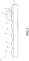
- the hydrophobic coating 16 may exhibit a water contact angle ( ⁇ ) with a water droplet 17 of 90° or more.
- the water contact angle ( ⁇ ) of the hydrophobic coating 16 may exceed 150°, in which case the hydrophobic coating 16 may be superhydrophobic/icephobic as well. Therefore, although termed "hydrophobic", it will be understood that the hydrophobic coating 16 may also exhibit superhydrophobic/icephobic properties depending on the magnitude of its water contact angle ( ⁇ ).
- the article 10 may be a commercial aircraft wing, and the surface 14 may be a leading edge of the commercial aircraft wing.
- the hydrophobic coating 16 may protect the leading edge of the wing from ice buildup, and may reduce or eliminate the need for wiring used to actively heat the leading edge.
- the article 10 may be any other type of part which may benefit from hydrophobic and/or superhydrophobic/icephobic properties such as, but not limited to, a telephone or power wire, a pipe, a bridge, or various types of marine equipment.
- the hydrophobic coating 16 may have a roughened surface which may at least partially contribute to the hydrophobicity of the hydrophobic coating 16. This is because air molecules, which are highly hydrophobic, may become entrapped in the protruding surface structures of a roughened surface and repel water and ice.
- the hydrophobic coating 16 may include peaks 18 and valleys 20 along the surface of the coating, thereby creating a roughened surface.
- the average roughness (R a ) (or the average length between the peaks 18 and the valleys 20) of the hydrophobic coating 16 may be dependent on the diameter of the smallest particles forming the coating 16.
- the average roughness (R a ) of the hydrophobic coating 16 may range from about 1 nanometer to about 500 micrometers, or from about 1 nanometer to about 100 micrometers, but may extend well beyond this range such as into the subnanometer or millimeter range as well.
- the hydrophobic coating 16 may exhibit multi-length scale surface roughness in which the distance between the peaks 18 and the valleys 20 may vary by at least one order of magnitude (e.g., from nanoscale to microscale). Such multi-length scale surface roughness may be particularly advantageous for enhancing the hydrophobic or superhydrophobic/icephobic effect of the coating 16.
- the substrate 12 may be formed from a range of materials such as, but not limited to, polymers, composites, metals, metal alloys, ceramics, cermets, and combinations thereof.
- the hydrophobic coating 16 may be formed from one or more polymers, carbon, metals, metal alloys, composites, nanoparticles, and combinations thereof.
- the hydrophobic coating 16 is applied to the surface 14 of the substrate 12 by high velocity oxy-fuel coating spraying (HVOF).
- HVOF high velocity oxy-fuel coating spraying
- the thermal spray deposition parameters may be adjusted to tune the degree of melting of the particles forming the hydrophobic coating 16 in order to control the degree of surface roughness/hydrophobicity of the resulting coating as well as the strength of adhesion of the hydrophobic coating 16 to the surface 14 (see further details below).
- the thermal spray deposition parameters may be adjusted as necessary to arrive at a suitable or optimal degree of particle melting to balance substrate adhesion and surface roughness (see further details below).
- the thermal spray deposition process may be performed under atmospheric conditions and may be used to apply the hydrophobic coating 16 over a range of substrates at high deposition rates, including substrates having large surface areas (>>1 m 2 ) and/or surfaces with curved and/or irregular shapes.
- the substrate 12 may be selected from a range of products formed from a range of materials (e.g., polymers, metals, composites, ceramics, cermets, etc.) depending on the application of the article 10.
- the thermal spraying conditions may limit the selection of the substrate in some circumstances. For example, certain polymeric substrates may melt at the high temperature conditions required to melt or partially melt certain metal-based particles.
- the surface 14 of the substrate may be optionally treated to roughen the surface 14 and promote coating adhesion according to an optional block 24. Roughening of the surface 14 may be achieved by mechanical roughening (e.g., grit blasting) or by chemical roughening, such as by surface etching with solvent exposure.
- the hydrophobic coating 16 may then be applied to the surface 14 of the treated or untreated substrate 12 by thermal spraying according to a next block 26, as shown.
- the parameters used for the thermal spray deposition may be tuned as needed to control the degree of melting of the particles forming the hydrophobic coating 16, and, therefore, the hydrophobicity and durability of the resulting hydrophobic coating 16.
- the substrate 12 may be optionally heated or cooled prior to, during, or after the deposition of the hydrophobic coating 16 to further control the degree of melting of the particles.
- the hydrophobicity of the coating may optionally be enhanced by enhancing an oxide content of the coating (optional block 28) to lower the surface energy of the coating, as lower surface energy coating materials (e.g., oxides, etc.) tend to increase the water contact angle ( ⁇ ) of a coating.
- the oxide content of the hydrophobic coating 16 may be increased by passing a flame over (e.g., heating) the top layer of the coating without substantially melting the coating, although other methods may also be used.
- the hydrophobicity of the hydrophobic coating 16 is increased by applying one or more additional layers over the hydrophobic coating 16 according to an optional block 30.
- the additional layer(s) are generated from particles having a lower surface energy and/or a smaller size than the particles used to generate the hydrophobic coating 16, thereby lowering the surface energy and/or increasing the degree of multi-length scale roughness of the final coating.
- the additional layer(s) may each be a thin, single particle layer (e.g., a monolayer) (see FIGs. 8-9 and further details below).
- the hydrophobicity of the hydrophobic coating 16 may be enhanced by performing a combination of the optional blocks 28 and 30, as shown. If the hydrophobic coating 16 is not yet hydrophobic or superhydrophobic/icephobic upon completion of the block 26, treating the hydrophobic coating 16 according to the block 28 and/or the block 30 may boost the hydrophobicity of the coating 16 to a hydrophobic state (i.e., a water contact angle ( ⁇ ) of 90° or more) or even a superhydrophobic/icephobic state (i.e., a water content angle ( ⁇ ) of 150° or more).
- a hydrophobic state i.e., a water contact angle ( ⁇ ) of 90° or more
- a superhydrophobic/icephobic state i.e., a water content angle ( ⁇ ) of 150° or more.
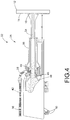
- the thermal spray apparatus 32 uses an HVOF spray torch 34.
- a coating precursor 38 may be fed into the thermal spray torch 34, as shown.
- the coating precursor 38 may be fed into the thermal spray torch 34 through an injector 40, with a feed line 42 providing the supply of the coating precursor 38 to the injector 40 (see FIG. 4 ).
- the coating precursor 38 may be in the form of a powder consisting of particles having an initial particle size and morphology.
- the term "morphology" refers to the shape of the particle.
- the average particle sizes of the powder may range from about 10 nanometers to about 100 micrometers, although particle sizes outside of this range may also be used in some circumstances.
- the coating precursor 38 may be in the form of a wire or a rod.
- the coating precursor 38 is then heated to at least a partially melted state with the thermal spray torch according to a next block 44. More specifically, at least some of the particles of the coating precursor 38 may be at least partially melted to promote the adhesion of the particles to the surface 14. In addition, at least some of the particles of the coating precursor 38 may be partially melted or fully unmelted such that the particles retain at least a fraction of their initial morphology to produce a rough surface upon impact with the substrate 12. As the thermal spray torch 34 is a HVOF type torch, heating of the coating precursor 38 may be achieved by injecting the particles into a gas stream 46 exiting an outlet of a combustion chamber 48 of the torch 34, as shown in FIG. 4 .
- Control over the degree of melting of the particles of the coating precursor 38 during the block 44 may be achieved by adjusting the temperature of the gas stream 46 by tuning various thermal spray deposition parameters, such as the fuel-to-oxygen ratio, the total volume of fuel and oxygen, and/or the feed rates of fuel and oxygen fed into the combustion chamber 48 from oxygen/fuel supply lines 50 (see FIG. 4 ).
- hydrophobic coatings may be produced using fuel-to-oxygen ratios of between about 0.5 to about 0.9, fuel feed rates of between about 4.68 to about 8,33 litres per hour (about 1.5 to about 2.2 gallons per hour (GPH)), and oxygen feed rates of between about 16.99 to about 25.49 cubic meters per hour (about 600 to about 900 standard cubic feet per hour (SCFH)).
- GPH gallons per hour
- SCFH standard cubic feet per hour
- the selection of the thermal spray parameters may take the thermal mass(es) (i.e., the energy required to melt) of the particles forming the coating precursor 38 into account, and the thermal mass(es) of the particles may be a function of the size, surface area, and porosity of the particles making up the coating precursor 38.
- the relative degree of melting of the different particles may also be tuned, at least to a degree, by varying the above parameters. It is also noted that if the coating precursor 38 contains polymeric particles, lower fuel-to-oxygen ratios (e.g., ⁇ 1) may be used to prevent complete melting and/or burning of the polymeric particles.
- the at least partially melted coating precursor particles may then be accelerated towards the surface 14 of the substrate 12 according to a next block 52. More specifically, the coating precursor particles may be accelerated toward the substrate 12 in a spray jet 54 flowing out of a nozzle 56 of the thermal spray torch 34, as shown in FIG. 4 . According to a next block 58, the coating precursor particles may then be allowed to impact the substrate 12 in a partially melted state in which a fraction of the initial particle morphology of at least some of the particles of the coating precursor 38 is retained.
- the retained initial particle morphology may be correlated with the roughness (e.g., average roughness (R a ), etc.) of the resulting hydrophobic coating 16, with smaller roughnesses compared to the initial particle size correlating with lower fractions of retained particle morphologies.
- the hydrophobic coating 16 may be provided according to a next block 60.
- a stand-off distance ( d ) between the thermal spray torch 34 and the substrate 12 may be varied during the blocks 52, 58, and 60 to regulate the amount of heating of the hydrophobic coating 16 and the substrate 12, with smaller stand-off distances (d) tending to cause increased heating of the hydrophobic coating/substrate as well as increased oxide contents in the hydrophobic coating 16. Greater stand-off distances (d) may allow the particles exiting the thermal spray torch 34 to at least partially unmelt and reach a more hardened state, thereby producing a more rough/hydrophobic surface upon impact with the substrate 12.
- a raster speed at which the thermal spray torch 34 is passed over the substrate 12 may also be varied during the blocks 52, 58, and 60 to regulate the degree of heating of the hydrophobic coating/substrate, with faster raster speeds reducing the degree of heating of the hydrophobic coating/substrate.
- raster speeds in the range of about 900 millimeters per second to about 1100 millimeters per second to produce hydrophobic coatings.
- raster speeds outside of this range may certainly be used in some circumstances depending on various factors such as, but not limited to, particle type, substrate type, other thermal spray settings, and/or the type of thermal spray equipment used.
- FIG. 5 provides a schematic representation of different particle compositions for which may be used as the coating precursor 38.
- coating precursor (A) it may consist of particles of a single component 62 having a single chemical identity and a single particle size and particle morphology.
- the component 62 may not fully melt during the thermal spray deposition process to ensure that at least some of the particles retain at least a fraction of their initial particle morphology upon impact with the substrate 12 to produce surface roughness.
- at least some of the particles of the component 62 may at least partially melt to ensure that the particles suitably adhere to the substrate 12.
- the coating precursor 38 may consist of a single component 63 having a single chemical identity, but with different particle sizes and particle morphologies. More specifically, the single component 63 may consist of a primary component 64 present at more than 50 weight percent and having a larger thermal mass (e.g., larger radius, less porous, and/or lower surface area, etc.) than a secondary component 65, such that the primary component 64 may require more energy/heat to melt. During the thermal spray deposition process, the primary component 64 may remain fully unmelted to promote surface roughness, provided that at least some of the particles of the secondary component 65 are at least partially melted to promote surface adhesion.
- a primary component 64 present at more than 50 weight percent and having a larger thermal mass (e.g., larger radius, less porous, and/or lower surface area, etc.) than a secondary component 65, such that the primary component 64 may require more energy/heat to melt.
- the primary component 64 may remain fully unmelted to promote surface roughness, provided that at least some of the particles of the secondary component
- the primary component 64 and the secondary component 65 may both be heated to partially melted states in which both the primary component 64 and the secondary component 65 may contribute to surface roughness, perhaps even multi-length scale surface roughness.
- multi-length scale surface roughness in hydrophobic coatings produced using coating precursor composition (B) may result from the different particle sizes of the primary component 64 and the secondary component 65 and/or the relative degrees of melting of the primary component 64 and the secondary component 65.
- coating precursor composition (B) may further include additional components with the same chemical identity but having different particle sizes and/or particle morphologies.
- the coating precursor 38 may consist of a mixture of two or more components having different chemical identities but the same particle size and particle morphology.
- the coating precursor composition (C) may include a primary component 66 present at more than 50 weight percent and a secondary component 67 present at less than 50 weight percent, although additional components may also be included.
- the primary component 66 may impart mechanical properties to the resulting hydrophobic coating 16 (e.g., hardness, fracture toughness, elastic modulus, surface adhesion, durability, wear resistance, etc.), while the secondary component 67 may impart hydrophobic and superhydrophobic/icephobic properties to the hydrophobic coating 16 (e.g., lower surface energy, roughness, etc.).
- the primary component 66 may be at least partially melted to promote surface adhesion, while the secondary component 67 may be at least partially unmelted so that it retains at least a fraction of its initial morphology and creates a rough/hydrophobic surface.
- both the primary component 66 and the secondary component 67 may contribute varying degrees of mechanical properties and hydrophobic properties to the hydrophobic coating 16.
- any multi-length scale surface roughness in hydrophobic coatings produced using coating precursor composition (C) may result from the relative degrees of melting of the primary component 66 and the secondary component 67.
- the particles of coating precursor composition (D) may include a mixture of two or more components having different chemical identities and different particle sizes and particle morphologies.
- coating precursor composition (D) may include a primary component 68 present at more than 50 weight percent and having a different chemical identity and particle size/morphology than a secondary component 69, although more than two components may also be used.
- the primary component 68 and the secondary component 69 may impart either mechanical properties (e.g., hardness, fracture toughness, elastic modulus, surface adhesion, durability, wear resistance, etc.) or hydrophobic properties (e.g., roughness, lower surface energy, etc.) to the hydrophobic coating 16.
- the primary component 68 may be at least partially melted by the thermal spray deposition process to ensure that it sufficiently adheres to the substrate 12 and contributes to the durability of the resulting hydrophobic coating 16, while the secondary component 69 may be at least partially unmelted so that it retains at least a fraction of its initial particle morphology and contributes to the roughness of the resulting hydrophobic coating 16.
- the primary component 68 may be at least partially unmelted during the thermal spray deposition process so that it retains at least a fraction of its initial particle morphology, while the secondary component 69 may be at least partially melted so that it sufficiently adheres to the substrate 12.
- the primary component 68 and the secondary component 69 may each contribute varying degrees of mechanical properties and hydrophobic properties as well.
- any multi-length scale surface roughness in hydrophobic coatings produced with coating precursor composition (D) may result from the different particle sizes of the primary component 68 and the secondary component 69 and/or varying degrees of melting of the primary component 68 and the secondary component 69.
- FIG. 6 shows a schematic representation of a hydrophobic coating 16 prepared using coating precursor composition (C), wherein the primary component 66 and the secondary component 67 have different chemical identities but the same particle size and particle morphology.
- the primary component 66 may be particles of poly ether ether ketone (PEEK) which may contribute mechanical properties to the hydrophobic coating 16
- the secondary component 67 may be particles of polytetrafluroethylene (PTFE) which has a lower surface energy and may contribute hydrophobic properties to the hydrophobic coating 16.
- FIG. 7 is a schematic representation of a hydrophobic coating 16 prepared using coating precursor composition (D), wherein the primary component 68 and the secondary component 69 have different chemical identities and different particle sizes/morphologies.
- the primary component 68 may formed from PEEK particles and the secondary component 69 may be formed from PTFE particles, although several other combinations are also possible.
- the block 30 may be carried out by first feeding the thermal spray torch 34 with secondary particles 72 according to a block 74, as described above (i.e., block 36).
- the secondary particles 72 may have a lower surface energy and/or a particle size that is at least one order of magnitude smaller than the coating precursor particles 38 used to produce the hydrophobic coating 16.
- the secondary particles 72 may then be heated with the thermal spray torch 34 to at least a partially melted state, accelerated towards the substrate 12, and allowed to impact the substrate 12 in a partially melted state in which a fraction of the initial particle morphology of at least some of the secondary particles 72 is retained to provide the additional layer 70 on the hydrophobic coating 16 (blocks 76, 78, 80, and 82).
- the degree of melting of the secondary particles 72 during the blocks 76, 78, and 80 may be tuned by varying the thermal spray deposition parameters such as the fuel-to-oxygen ratio, the total fuel and oxygen volume, the fuel and oxygen feed rates, the stand-off distance ( d ), and/or the raster speed of the thermal spray torch 34.
- the thermal spray deposition parameters may be tuned to ensure that the secondary particles 72 are melted enough to promote adhesion to the hydrophobic coating 16, but not fully melted such that the at least some of the secondary particles 72 retain a fraction of their initial particle morphology to enhance surface roughness.
- the resulting hydrophobic coating 16 may have an enhanced hydrophobicity (as shown by a higher water contact angle ( ⁇ ) with a water droplet 17) as a consequence of the lower surface energy provided by the secondary particles 72 and/or the enhanced surface roughness provided by the smaller secondary particles 72.
- the additional layer 70 may introduce multi-length scale surface roughness into the hydrophobic coating 16.
- subsequent additional layers 70 may be deposited on the hydrophobic coating 16 by repeating the method of FIGs. 8-9 , wherein each subsequent additional layer 70 has a particle size that is smaller than the particle size of the previous layer.
- the additional layer(s) 70 may each be a very thin layer, such as a monolayer (e.g., with single particle thickness), that is substantially thinner than the hydrophobic coating 16.
- each additional layer 70 may be a monolayer of the secondary particles 72 covering between about 70% to about 150% of the surface of the hydrophobic coating 16, although the surface coverage of the secondary particles 72 may extend beyond this range in some circumstances. Accordingly, the additional layer(s) 70 may be at least partially transparent such that the hydrophobic coating 16 may be visible through the additional layer(s) 70.
- thermoplastic polymer powders such as polyether ether ketone (PEEK).
- PEEK polyether ether ketone
- HVOF thermal spray equipment was used to deposit PEEK powders having a 50 micrometer particle diameter according to the method of FIGs. 3-4 . Since typical HVOF thermal spray processes heat particles to temperatures in excess of 1000°, the HVOF thermal spray torch was set to a low fuel-to-oxygen ratio ( ⁇ 0.65) and higher stand-off distances ( d ) to reduce total heat input into the PEEK particles and prevent complete melting and/or burning of the polymer particles.
- Table I shows the mean roughness depth (R z ), the average roughness (R a ), and the relative oxide content of PEEK coatings produced by HVOF thermal spraying at various stand-off distances (d).
- the roughness of the PEEK coatings increases with increasing stand-off distances ( d ) due to decreased heating/melting of the PEEK particles at higher stand-off distances ( d ).
- lower stand-off distances ( d ) leads to higher oxide contents (i.e., lower surface energies) due to increased heating of the deposited film which enhances the oxide content.
- the thermal spray parameters may be varied to control the roughness, the oxide content, and the ultimate degree of hydrophobicity of PEEK coatings. Table 1.
- FIG. 10 shows the water contact angle ( ⁇ ) of various polymer-based coatings as a function of stand-off distance ( d ) at a fuel-to-oxygen ratio of ⁇ 0.65.
- the hydrophobicity (i.e., water contact angle ( ⁇ )) of pure PEEK coatings produced from 50 micrometer PEEK particles generally increases with increased stand-off distances (d) due to decreased heating/melting and roughness of the deposited PEEK particles.
- the disclosure herein may be used to produce hydrophobic and superhydrophobic/icephobic coatings from a variety of precursor materials such as, but not limited to, polymer powders, metal or metal alloy powders, polymer powder and metal/metal alloy powder mixtures, and polymer powder and polymeric or metal/metal alloy nanoparticle mixtures by tuning the thermal spray deposition parameters.
- precursor materials such as, but not limited to, polymer powders, metal or metal alloy powders, polymer powder and metal/metal alloy powder mixtures, and polymer powder and polymeric or metal/metal alloy nanoparticle mixtures by tuning the thermal spray deposition parameters.
- composite materials e.g., polymers loaded with nanoparticles, etc.
- thermal spray coatings disclosed herein may also be used to impart other types of properties to substrate surfaces as well such as, but not limited to, anti-fouling properties, conductive properties, and/or biocidal properties.
- coatings formed from metal nanoparticles may impart conductive properties or biocidal properties (e.g., copper nanoparticles), while certain types of polymers (e.g., zwitterionic polymers, etc.) may be used to impart anti-fouling properties.
- the technology disclosed herein has industrial applicability in a variety of settings such as, but not limited to, industrial applications which may benefit from components having hydrophobic and superhydrophobic/icephobic surfaces.
- the technology disclosed herein relies solely on thermal spray deposition methods to produce hydrophobic and superhydrophobic/icephobic coatings from a range of starting precursor powders, including polymeric powders.
- the methods of the present disclosure may be used to apply durable hydrophobic and superhydrophobic/icephobic coatings on a variety of industrial products, even products with large surface areas (e.g., marine equipment, bridges, pipes, aircraft wings, etc.), at high deposition rates and under atmospheric conditions.
- thermal spray technologies are typically used to apply smooth metallic, ceramic, or cermet coatings
- the present disclosure implements thermal spray deposition processes to produce roughened/hydrophobic coatings by controlling the degree of melting of the coating precursors such that at least a fraction of the initial particle morphology is retained upon impact with the substrate.
- the degree of melting and the roughness of the resulting coating may be tuned by varying the thermal spray deposition parameters such as the fuel-to-oxygen ratio, the stand-off distance ( d ), the fuel and oxygen feed rates, and the raster speed. It is expected that the technology disclosed herein may find wide industrial applicability in a wide range of areas such as, but not limited to, aerospace, marine, power, transportation, construction, and defense industries.
Landscapes
- Chemical & Material Sciences (AREA)
- Engineering & Computer Science (AREA)
- Materials Engineering (AREA)
- Organic Chemistry (AREA)
- Mechanical Engineering (AREA)
- Chemical Kinetics & Catalysis (AREA)
- Physics & Mathematics (AREA)
- Metallurgy (AREA)
- Plasma & Fusion (AREA)
- Life Sciences & Earth Sciences (AREA)
- Wood Science & Technology (AREA)
- Coating By Spraying Or Casting (AREA)
- Application Of Or Painting With Fluid Materials (AREA)
Claims (15)
- Verfahren zum Bilden einer hydrophoben Beschichtung (16) auf einem Substrat (12) durch einen Wärmespraybeschichtungsvorgang, das aufweist:Speisen einer Wärmesprayvorrichtung (32) mit einem Beschichtungsvorläufer (38), wobei der Beschichtungsvorläufer (38) Beschichtungsvorläuferpartikel mit einer anfänglichen Partikelmorphologie (Block 36) umfasst;Erwärmen der Beschichtungsvorläuferpartikel mit der Wärmesprayvorrichtung (32), um die Beschichtungsvorläuferpartikel zumindest teilweise schmelzen zu lassen (Block 44);Beschleunigen der Beschichtungsvorläuferpartikel in Richtung des Substrats (12) unter Verwendung der Wärmesprayvorrichtung (32; Block 52); undBilden der hydrophoben Beschichtung (16) auf dem Substrat (12), indem man die Beschichtungsvorläuferpartikel auf das Substrat (12) in einem teilweise geschmolzenem Zustand prallen lässt, in welchem ein Bruchteil der anfänglichen Partikelmorphologie von zumindest einigen der Beschichtungsvorläuferpartikel beibehalten wird (Block 58);Applizieren einer zusätzlichen Schicht (70) auf der hydrophoben Beschichtung (16) durch einen Wärmespraybeschichtungsvorgang, der aufweist:Speisen der Wärmesprayvorrichtung (32) mit sekundären Partikeln (72), die eine anfängliche sekundäre Partikelmorphologie aufweisen, wobei die sekundären Partikel (72) eine geringere Oberflächenenergie und/oder eine kleinere Partikelgröße als die Beschichtungsvorläuferpartikel aufweisen (Block 74);Erwärmen der sekundären Partikel (72) mit der Wärmesprayvorrichtung (32), um die sekundären Partikel (72) zumindest teilweise schmelzen zu lassen (Block 76);Beschleunigen der sekundären Partikel (72) in Richtung des Substrats (12) unter Verwendung der Wärmesprayvorrichtung (32; Block 78); undBilden der zusätzlichen Schicht (70) auf der hydrophoben Beschichtung (16), indem man die sekundären Partikel (72) auf die hydrophobe Beschichtung (16) in einem teilweise geschmolzenem Zustand prallen lässt, in welchem ein Bruchteil der anfänglichen sekundären Partikelmorphologie von zumindest einigen der sekundären Partikel (72) beibehalten wird (Block 80),wobei die Wärmesprayvorrichtung (32) eine HVOF-Sprühfackel ist.
- Verfahren nach Anspruch 1, wobei die zusätzliche Schicht (70) eine Monoschicht ist, die zwischen 70 % und 150 % einer Fläche der hydrophoben Beschichtung (16) bedeckt.
- Verfahren nach Anspruch 1 oder 2, wobei die sekundären Partikel (72) eine Partikelgröße (65, 69) aufweisen, die um zumindest eine Größenordnung kleiner als die Beschichtungsvorläuferpartikel ist.
- Verfahren nach einem der Ansprüche 1 bis 3, wobei die hydrophobe Beschichtung (16) eine zusätzliche Schicht (70) umfasst und wobei die hydrophobe Beschichtung (16) eine Mehrfachlängenskala-Oberflächenrauheit zeigt.
- Verfahren nach einem der Ansprüche 1 bis 4, wobei eine mittlere Rauheit der hydrophoben Beschichtung (16) von 1 Nanometer bis 500 Mikrometern reicht.
- Verfahren nach einem der Ansprüche 1 bis 4, wobei die hydrophobe Beschichtung (16) eine mittlere Rauheit zwischen 1 Nanometer und 100 Mikrometern zeigt.
- Verfahren nach einem der Ansprüche 1 bis 6, wobei der Beschichtungsvorläufer (38) ein Pulver mit einer mittleren Partikelgröße zwischen 10 Nanometern und 100 Mikrometern aufweist.
- Verfahren nach einem der Ansprüche 1 bis 7, wobei ein Erwärmen der Beschichtungsvorläuferpartikel mit der Wärmesprayvorrichtung (32), um die Beschichtungsvorläuferpartikel zumindest teilweise schmelzen zu lassen, ein Steuern einer Temperatur einer Gasströmung der Wärmesprayvorrichtung (32) aufweist, indem eine Sauerstoffzuführrate und eine Brennstoffzuführrate der Wärmesprayvorrichtung (32) eingestellt werden.
- Verfahren nach einem der Ansprüche 1 bis 6, wobei ein Bilden der hydrophoben Beschichtung (16) auf dem Substrat (12), indem man die Beschichtungsvorläuferpartikel auf das Substrat (12) in einem zumindest teilweise geschmolzenem Zustand prallen lässt, ein Einstellen eines Sicherheitsabstands d zwischen der Wärmesprayvorrichtung (32) und dem Substrat (12) aufweist.
- Verfahren nach einem der Ansprüche 1 bis 9, das ferner ein Erwärmen der hydrophoben Beschichtung (16) aufweist, um einen Oxidgehalt der hydrophoben Beschichtung zu verstärken (Block 28).
- Verfahren nach einem der Ansprüche 1 bis 10, wobei der Beschichtungsvorläufer (38) aus einer einzigen Komponente (62) besteht, die eine einzige chemische Identität mit einer einzigen Partikelgröße und einer einzigen Partikelmorphologie aufweist.
- Verfahren nach einem der Ansprüche 1 bis 10, wobei der Beschichtungsvorläufer (38) aus einer primären Komponente (64) und einer sekundären Komponente (65), die eine kleinere Wärmemasse als die primäre Komponente (64) aufweist, besteht, wobei die primäre Komponente (64) und die sekundäre Komponente (65) die gleiche chemische Identität, aber eine unterschiedliche Partikelgröße und eine unterschiedliche Partikelmorphologie aufweisen, und wobei der Beschichtungsvorläufer (38) aus mehr als 50 Masseprozenten der primären Komponente (64) besteht.
- Verfahren nach einem der Ansprüche 1 bis 10, wobei der Beschichtungsvorläufer (38) aus einer primären Komponente (66) und einer sekundären Komponente (67) besteht, wobei die primäre Komponente (66) und die sekundäre Komponente (67) eine unterschiedliche chemische Identität und eine gleiche Partikelgröße und eine gleiche Partikelmorphologie aufweisen, und wobei der Beschichtungsvorläufer (38) aus mehr als 50 Masseprozenten der primären Komponente (66) besteht.
- Verfahren nach einem der Ansprüche 1 bis 10, wobei der Beschichtungsvorläufer aus einer primären Komponente (68) und einer sekundären Komponente (69) besteht, wobei die primäre Komponente (68) und die sekundäre Komponente (69) eine unterschiedliche chemische Identität und eine unterschiedliche Partikelgröße und eine unterschiedliche Partikelmorphologie aufweisen, und wobei der Beschichtungsvorläufer (38) aus mehr als 50 Masseprozenten der primären Komponente (68) besteht.
- Verfahren nach einem der Ansprüche 1 bis 14, wobei das Substrat (12) aus Polymeren, Verbundstoffen, Metallen, Metalllegierungen, Keramiken, Metallkeramiken oder Kombinationen davon gebildet wird.
Applications Claiming Priority (1)
| Application Number | Priority Date | Filing Date | Title |
|---|---|---|---|
| US14/508,846 US11459481B2 (en) | 2014-10-07 | 2014-10-07 | Thermal spray for durable and large-area hydrophobic and superhydrophobic/icephobic coatings |
Publications (2)
| Publication Number | Publication Date |
|---|---|
| EP3006590A1 EP3006590A1 (de) | 2016-04-13 |
| EP3006590B1 true EP3006590B1 (de) | 2021-03-31 |
Family
ID=54359706
Family Applications (1)
| Application Number | Title | Priority Date | Filing Date |
|---|---|---|---|
| EP15185897.4A Active EP3006590B1 (de) | 2014-10-07 | 2015-09-18 | Wärmespray für dauerhafte und grossflächige hydrophobe und superhydrophobe/eisabstossende beschichtungen |
Country Status (4)
| Country | Link |
|---|---|
| US (1) | US11459481B2 (de) |
| EP (1) | EP3006590B1 (de) |
| JP (2) | JP7036530B2 (de) |
| CA (1) | CA2897696C (de) |
Families Citing this family (9)
| Publication number | Priority date | Publication date | Assignee | Title |
|---|---|---|---|---|
| US11459481B2 (en) | 2014-10-07 | 2022-10-04 | The Boeing Company | Thermal spray for durable and large-area hydrophobic and superhydrophobic/icephobic coatings |
| DE102017131397A1 (de) * | 2017-12-28 | 2019-07-04 | Raantec Gmbh & Co. Kg | Verfahren und Vorrichtung zum Versiegeln eines Fügespalts |
| US12054638B2 (en) | 2019-08-01 | 2024-08-06 | The Boeing Company | Transparent hydrophobic and icephobic compositions, coatings, and methods |
| JP2021066943A (ja) * | 2019-10-25 | 2021-04-30 | 株式会社エンプラス | 複合凹凸構造体の製造方法およびその用途 |
| CN115210296B (zh) | 2019-12-11 | 2023-06-13 | 适应性表面技术股份有限公司 | 侧链官能化的有机硅氧烷聚合物、涂料组合物及其防冰涂料 |
| CN112030095A (zh) * | 2020-08-14 | 2020-12-04 | 北京科技大学 | 一种在工件表面超音速火焰喷涂耐磨耐蚀镍铬涂层的方法 |
| CN115029655B (zh) * | 2022-05-12 | 2023-07-18 | 山东科技大学 | 一种超疏水铁基非晶梯度涂层及其制备方法 |
| CN115478242B (zh) * | 2022-09-16 | 2024-02-20 | 西安交通大学 | 一种基于表面高硬度凸点强化的高耐磨超疏水涂层及其大面积制备方法 |
| CN118773599B (zh) * | 2024-07-25 | 2026-04-21 | 西安交通大学 | 一种增强涂层抗剪切强度的沉积体及其喷涂方法 |
Citations (2)
| Publication number | Priority date | Publication date | Assignee | Title |
|---|---|---|---|---|
| WO2006115558A2 (en) * | 2005-04-27 | 2006-11-02 | Ferro Corporation | Process for structuring self-cleaning glass surfaces |
| US20080311382A1 (en) * | 2005-02-02 | 2008-12-18 | Christoph Stecher | Article with Anti-Adhesion Coating and Method for Production |
Family Cites Families (27)
| Publication number | Priority date | Publication date | Assignee | Title |
|---|---|---|---|---|
| JPH02217458A (ja) | 1989-02-20 | 1990-08-30 | Nkk Corp | セラミックスとプラスチックの混合溶射法 |
| US5250356A (en) * | 1992-08-28 | 1993-10-05 | E. I. Du Pont De Nemours And Company | Cookware coating system |
| JPH0827555A (ja) * | 1994-07-12 | 1996-01-30 | Nippon Steel Corp | 溶融金属めっき用スリットノズル |
| US6660363B1 (en) | 1994-07-29 | 2003-12-09 | Wilhelm Barthlott | Self-cleaning surfaces of objects and process for producing same |
| US5716422A (en) * | 1996-03-25 | 1998-02-10 | Wilson Greatbatch Ltd. | Thermal spray deposited electrode component and method of manufacture |
| EP0988898A3 (de) | 1998-09-23 | 2001-05-02 | Camco International Inc. | Verfahren zum thermischen Besprühen von polymeren Materialien |
| US6136453A (en) * | 1998-11-24 | 2000-10-24 | General Electric Company | Roughened bond coat for a thermal barrier coating system and method for producing |
| US6327452B1 (en) * | 2000-02-14 | 2001-12-04 | Xerox Corporation | Donor rolls and methods of making donor rolls |
| AUPQ859000A0 (en) * | 2000-07-06 | 2000-07-27 | Commonwealth Scientific And Industrial Research Organisation | Apparatus for surface engineering |
| US6838157B2 (en) * | 2002-09-23 | 2005-01-04 | Siemens Westinghouse Power Corporation | Method and apparatus for instrumenting a gas turbine component having a barrier coating |
| JP2004283699A (ja) * | 2003-03-20 | 2004-10-14 | Osaka Gas Co Ltd | 高耐久性コーティングを施したガス使用設備用部材 |
| AU2003901734A0 (en) * | 2003-04-11 | 2003-05-01 | Unisearch Limited | Transparent superhydrophobic coating |
| JP2006083279A (ja) | 2004-09-15 | 2006-03-30 | Seiko Epson Corp | 撥液性粒子および撥液性粒子の製造方法 |
| US7579088B2 (en) * | 2004-12-02 | 2009-08-25 | Henkel Kommanditgesellschaft Auf Aktien (Henkel Kgaa) | Increasing and maintaining the hydrophilic nature of an oxidized plastic surface |
| WO2007089620A1 (en) | 2006-01-26 | 2007-08-09 | Xiom Corporation | Powder thermal spray compositions composing at least two thermoplastics |
| US7946303B2 (en) * | 2006-09-29 | 2011-05-24 | Lam Research Corporation | Carrier for reducing entrance and/or exit marks left by a substrate-processing meniscus |
| JP5558807B2 (ja) * | 2007-03-22 | 2014-07-23 | 株式会社東芝 | 真空成膜装置用部品及び真空成膜装置 |
| GB2467780A (en) | 2009-02-16 | 2010-08-18 | Univ Sheffield | Liquid Composite Materials |
| JP4884492B2 (ja) * | 2009-03-13 | 2012-02-29 | 株式会社フジコー | 光触媒機能皮膜の形成方法 |
| DE102010000344A1 (de) * | 2010-02-09 | 2011-08-11 | BAF Industrie- und Oberflächentechnik GmbH, 36452 | Metallisches Bauteil, Verfahren zur Herstellung eines metallischen Bauteils und Beschlag, Möbel und/oder Haushaltsgroßgerät |
| JP6136625B2 (ja) * | 2012-06-25 | 2017-05-31 | 新日鐵住金株式会社 | 熱間加工用潤滑剤および潤滑被膜ならびに熱間加工方法 |
| ES2648229T3 (es) | 2012-09-27 | 2017-12-29 | Shield Aerodynamics Llc | Escudo de defensa ambiental |
| US9670304B2 (en) | 2012-11-05 | 2017-06-06 | Liang Wang | Composite for preventing ice adhesion |
| US20140178641A1 (en) | 2012-12-21 | 2014-06-26 | General Electric Company | Methods of coating a surface and articles with coated surface |
| KR101519709B1 (ko) * | 2013-03-05 | 2015-05-12 | 기아자동차주식회사 | 고속화염용사 코팅법과 플라즈마 이온 질화법를 이용한 금형의 보정 및 재생 방법 |
| US11459481B2 (en) | 2014-10-07 | 2022-10-04 | The Boeing Company | Thermal spray for durable and large-area hydrophobic and superhydrophobic/icephobic coatings |
| CN105316619B (zh) * | 2015-10-29 | 2018-01-23 | 中国科学院宁波材料技术与工程研究所 | 一种利用热喷涂技术制备耐磨超疏水陶瓷涂层的方法及其产品 |
-
2014
- 2014-10-07 US US14/508,846 patent/US11459481B2/en active Active
-
2015
- 2015-07-17 CA CA2897696A patent/CA2897696C/en active Active
- 2015-07-17 JP JP2015142860A patent/JP7036530B2/ja active Active
- 2015-09-18 EP EP15185897.4A patent/EP3006590B1/de active Active
-
2021
- 2021-11-22 JP JP2021189429A patent/JP7279143B2/ja active Active
Patent Citations (2)
| Publication number | Priority date | Publication date | Assignee | Title |
|---|---|---|---|---|
| US20080311382A1 (en) * | 2005-02-02 | 2008-12-18 | Christoph Stecher | Article with Anti-Adhesion Coating and Method for Production |
| WO2006115558A2 (en) * | 2005-04-27 | 2006-11-02 | Ferro Corporation | Process for structuring self-cleaning glass surfaces |
Also Published As
| Publication number | Publication date |
|---|---|
| JP7036530B2 (ja) | 2022-03-15 |
| CA2897696C (en) | 2021-06-08 |
| JP7279143B2 (ja) | 2023-05-22 |
| EP3006590A1 (de) | 2016-04-13 |
| CA2897696A1 (en) | 2016-04-07 |
| US20160096972A1 (en) | 2016-04-07 |
| US11459481B2 (en) | 2022-10-04 |
| JP2016074970A (ja) | 2016-05-12 |
| JP2022022255A (ja) | 2022-02-03 |
Similar Documents
| Publication | Publication Date | Title |
|---|---|---|
| EP3006590B1 (de) | Wärmespray für dauerhafte und grossflächige hydrophobe und superhydrophobe/eisabstossende beschichtungen | |
| Ravi et al. | Fabrication of micro-/nano-structured super-hydrophobic fluorinated polymer coatings by cold-spray | |
| CN103819705B (zh) | 热喷涂的增强聚合物复合材料 | |
| Liao et al. | Anti-icing performance of ZnO/SiO2/PTFE sandwich-nanostructure superhydrophobic film on glass prepared via RF magnetron sputtering | |
| US10308999B2 (en) | Iron-based alloy coating and method for manufacturing the same | |
| Sahab et al. | Impact of plasma spray variables parameters on mechanical and wear behaviour of plasma sprayed Al2O3 3% wt TiO2 coating in abrasion and erosion application | |
| JP4982859B2 (ja) | 有機皮膜の形成方法 | |
| JP5143820B2 (ja) | 疎水性ガラス表面 | |
| KR102470075B1 (ko) | 희토류 산화물 층을 포함하는 조리용 물품 | |
| JP2000096203A (ja) | ポリマ―材料の溶射適用方法 | |
| Djendel et al. | Characterization of alumina-titania coatings produced by atmospheric plasma spraying on 304 SS steel | |
| CN109735785A (zh) | 一种新型耐高温耐磨机械性能良好的疏水涂层的制备方法 | |
| KR20230146585A (ko) | 분말 코팅 조성물 | |
| Sarkar et al. | One-step deposition process to obtain nanostructured superhydrophobic thin films by galvanic exchange reactions | |
| Lin et al. | Using response surface methodology with response transformation in optimizing plasma spraying coatings | |
| CN103649412A (zh) | 防污清洁刮刀 | |
| Wang et al. | Preparation of robust superhydrophobic surface on PET substrate using Box-Behnken design and facile sanding method with PTFE powder | |
| CN114381683B (zh) | 基体防护涂层的制备方法 | |
| JP5598901B2 (ja) | 樹脂コーティング部材と樹脂コーティング方法 | |
| Abhijith et al. | Effect of Heat Treatment on Mechanical Properties and Corrosion Response of HVOF Sprayed High Entropy Alloy Coatings | |
| KR100797827B1 (ko) | 탄소섬유-에폭시 복합재에의 코팅방법 | |
| RU2858403C1 (ru) | Способ получения многослойного антифрикционного покрытия системы Cu-Sn-баббит на стальной подложке | |
| Alikhanifaradonbeh et al. | Nonfluorinated Superhydrophobic TiO2-Based Coatings by Suspension Flame Spraying | |
| Altuncu et al. | Solid particle erosive wear behaviour of flame sprayed ceramic coatings | |
| Rahim et al. | Plasma spray ceramic coating and measurement of developed coating behaviour |
Legal Events
| Date | Code | Title | Description |
|---|---|---|---|
| PUAI | Public reference made under article 153(3) epc to a published international application that has entered the european phase |
Free format text: ORIGINAL CODE: 0009012 |
|
| 17P | Request for examination filed |
Effective date: 20150918 |
|
| AK | Designated contracting states |
Kind code of ref document: A1 Designated state(s): AL AT BE BG CH CY CZ DE DK EE ES FI FR GB GR HR HU IE IS IT LI LT LU LV MC MK MT NL NO PL PT RO RS SE SI SK SM TR |
|
| AX | Request for extension of the european patent |
Extension state: BA ME |
|
| RBV | Designated contracting states (corrected) |
Designated state(s): AL AT BE BG CH CY CZ DE DK EE ES FI FR GB GR HR HU IE IS IT LI LT LU LV MC MK MT NL NO PL PT RO RS SE SI SK SM TR |
|
| STAA | Information on the status of an ep patent application or granted ep patent |
Free format text: STATUS: EXAMINATION IS IN PROGRESS |
|
| 17Q | First examination report despatched |
Effective date: 20180718 |
|
| GRAP | Despatch of communication of intention to grant a patent |
Free format text: ORIGINAL CODE: EPIDOSNIGR1 |
|
| STAA | Information on the status of an ep patent application or granted ep patent |
Free format text: STATUS: GRANT OF PATENT IS INTENDED |
|
| INTG | Intention to grant announced |
Effective date: 20201028 |
|
| GRAS | Grant fee paid |
Free format text: ORIGINAL CODE: EPIDOSNIGR3 |
|
| GRAA | (expected) grant |
Free format text: ORIGINAL CODE: 0009210 |
|
| STAA | Information on the status of an ep patent application or granted ep patent |
Free format text: STATUS: THE PATENT HAS BEEN GRANTED |
|
| AK | Designated contracting states |
Kind code of ref document: B1 Designated state(s): AL AT BE BG CH CY CZ DE DK EE ES FI FR GB GR HR HU IE IS IT LI LT LU LV MC MK MT NL NO PL PT RO RS SE SI SK SM TR |
|
| REG | Reference to a national code |
Ref country code: GB Ref legal event code: FG4D Ref country code: CH Ref legal event code: EP |
|
| REG | Reference to a national code |
Ref country code: DE Ref legal event code: R096 Ref document number: 602015067398 Country of ref document: DE Ref country code: AT Ref legal event code: REF Ref document number: 1377012 Country of ref document: AT Kind code of ref document: T Effective date: 20210415 |
|
| REG | Reference to a national code |
Ref country code: IE Ref legal event code: FG4D |
|
| REG | Reference to a national code |
Ref country code: LT Ref legal event code: MG9D |
|
| PG25 | Lapsed in a contracting state [announced via postgrant information from national office to epo] |
Ref country code: NO Free format text: LAPSE BECAUSE OF FAILURE TO SUBMIT A TRANSLATION OF THE DESCRIPTION OR TO PAY THE FEE WITHIN THE PRESCRIBED TIME-LIMIT Effective date: 20210630 Ref country code: BG Free format text: LAPSE BECAUSE OF FAILURE TO SUBMIT A TRANSLATION OF THE DESCRIPTION OR TO PAY THE FEE WITHIN THE PRESCRIBED TIME-LIMIT Effective date: 20210630 Ref country code: FI Free format text: LAPSE BECAUSE OF FAILURE TO SUBMIT A TRANSLATION OF THE DESCRIPTION OR TO PAY THE FEE WITHIN THE PRESCRIBED TIME-LIMIT Effective date: 20210331 Ref country code: HR Free format text: LAPSE BECAUSE OF FAILURE TO SUBMIT A TRANSLATION OF THE DESCRIPTION OR TO PAY THE FEE WITHIN THE PRESCRIBED TIME-LIMIT Effective date: 20210331 |
|
| PG25 | Lapsed in a contracting state [announced via postgrant information from national office to epo] |
Ref country code: RS Free format text: LAPSE BECAUSE OF FAILURE TO SUBMIT A TRANSLATION OF THE DESCRIPTION OR TO PAY THE FEE WITHIN THE PRESCRIBED TIME-LIMIT Effective date: 20210331 Ref country code: LV Free format text: LAPSE BECAUSE OF FAILURE TO SUBMIT A TRANSLATION OF THE DESCRIPTION OR TO PAY THE FEE WITHIN THE PRESCRIBED TIME-LIMIT Effective date: 20210331 Ref country code: SE Free format text: LAPSE BECAUSE OF FAILURE TO SUBMIT A TRANSLATION OF THE DESCRIPTION OR TO PAY THE FEE WITHIN THE PRESCRIBED TIME-LIMIT Effective date: 20210331 |
|
| REG | Reference to a national code |
Ref country code: NL Ref legal event code: MP Effective date: 20210331 |
|
| REG | Reference to a national code |
Ref country code: AT Ref legal event code: MK05 Ref document number: 1377012 Country of ref document: AT Kind code of ref document: T Effective date: 20210331 |
|
| PG25 | Lapsed in a contracting state [announced via postgrant information from national office to epo] |
Ref country code: LT Free format text: LAPSE BECAUSE OF FAILURE TO SUBMIT A TRANSLATION OF THE DESCRIPTION OR TO PAY THE FEE WITHIN THE PRESCRIBED TIME-LIMIT Effective date: 20210331 Ref country code: NL Free format text: LAPSE BECAUSE OF FAILURE TO SUBMIT A TRANSLATION OF THE DESCRIPTION OR TO PAY THE FEE WITHIN THE PRESCRIBED TIME-LIMIT Effective date: 20210331 Ref country code: CZ Free format text: LAPSE BECAUSE OF FAILURE TO SUBMIT A TRANSLATION OF THE DESCRIPTION OR TO PAY THE FEE WITHIN THE PRESCRIBED TIME-LIMIT Effective date: 20210331 Ref country code: EE Free format text: LAPSE BECAUSE OF FAILURE TO SUBMIT A TRANSLATION OF THE DESCRIPTION OR TO PAY THE FEE WITHIN THE PRESCRIBED TIME-LIMIT Effective date: 20210331 Ref country code: AT Free format text: LAPSE BECAUSE OF FAILURE TO SUBMIT A TRANSLATION OF THE DESCRIPTION OR TO PAY THE FEE WITHIN THE PRESCRIBED TIME-LIMIT Effective date: 20210331 Ref country code: SM Free format text: LAPSE BECAUSE OF FAILURE TO SUBMIT A TRANSLATION OF THE DESCRIPTION OR TO PAY THE FEE WITHIN THE PRESCRIBED TIME-LIMIT Effective date: 20210331 |
|
| PG25 | Lapsed in a contracting state [announced via postgrant information from national office to epo] |
Ref country code: PL Free format text: LAPSE BECAUSE OF FAILURE TO SUBMIT A TRANSLATION OF THE DESCRIPTION OR TO PAY THE FEE WITHIN THE PRESCRIBED TIME-LIMIT Effective date: 20210331 Ref country code: PT Free format text: LAPSE BECAUSE OF FAILURE TO SUBMIT A TRANSLATION OF THE DESCRIPTION OR TO PAY THE FEE WITHIN THE PRESCRIBED TIME-LIMIT Effective date: 20210802 Ref country code: ES Free format text: LAPSE BECAUSE OF FAILURE TO SUBMIT A TRANSLATION OF THE DESCRIPTION OR TO PAY THE FEE WITHIN THE PRESCRIBED TIME-LIMIT Effective date: 20210331 Ref country code: SK Free format text: LAPSE BECAUSE OF FAILURE TO SUBMIT A TRANSLATION OF THE DESCRIPTION OR TO PAY THE FEE WITHIN THE PRESCRIBED TIME-LIMIT Effective date: 20210331 Ref country code: RO Free format text: LAPSE BECAUSE OF FAILURE TO SUBMIT A TRANSLATION OF THE DESCRIPTION OR TO PAY THE FEE WITHIN THE PRESCRIBED TIME-LIMIT Effective date: 20210331 Ref country code: IS Free format text: LAPSE BECAUSE OF FAILURE TO SUBMIT A TRANSLATION OF THE DESCRIPTION OR TO PAY THE FEE WITHIN THE PRESCRIBED TIME-LIMIT Effective date: 20210731 |
|
| REG | Reference to a national code |
Ref country code: DE Ref legal event code: R097 Ref document number: 602015067398 Country of ref document: DE |
|
| PG25 | Lapsed in a contracting state [announced via postgrant information from national office to epo] |
Ref country code: AL Free format text: LAPSE BECAUSE OF FAILURE TO SUBMIT A TRANSLATION OF THE DESCRIPTION OR TO PAY THE FEE WITHIN THE PRESCRIBED TIME-LIMIT Effective date: 20210331 Ref country code: DK Free format text: LAPSE BECAUSE OF FAILURE TO SUBMIT A TRANSLATION OF THE DESCRIPTION OR TO PAY THE FEE WITHIN THE PRESCRIBED TIME-LIMIT Effective date: 20210331 |
|
| PLBE | No opposition filed within time limit |
Free format text: ORIGINAL CODE: 0009261 |
|
| STAA | Information on the status of an ep patent application or granted ep patent |
Free format text: STATUS: NO OPPOSITION FILED WITHIN TIME LIMIT |
|
| 26N | No opposition filed |
Effective date: 20220104 |
|
| REG | Reference to a national code |
Ref country code: CH Ref legal event code: PL |
|
| REG | Reference to a national code |
Ref country code: BE Ref legal event code: MM Effective date: 20210930 |
|
| PG25 | Lapsed in a contracting state [announced via postgrant information from national office to epo] |
Ref country code: IS Free format text: LAPSE BECAUSE OF FAILURE TO SUBMIT A TRANSLATION OF THE DESCRIPTION OR TO PAY THE FEE WITHIN THE PRESCRIBED TIME-LIMIT Effective date: 20210731 Ref country code: MC Free format text: LAPSE BECAUSE OF FAILURE TO SUBMIT A TRANSLATION OF THE DESCRIPTION OR TO PAY THE FEE WITHIN THE PRESCRIBED TIME-LIMIT Effective date: 20210331 |
|
| PG25 | Lapsed in a contracting state [announced via postgrant information from national office to epo] |
Ref country code: LU Free format text: LAPSE BECAUSE OF NON-PAYMENT OF DUE FEES Effective date: 20210918 Ref country code: IT Free format text: LAPSE BECAUSE OF FAILURE TO SUBMIT A TRANSLATION OF THE DESCRIPTION OR TO PAY THE FEE WITHIN THE PRESCRIBED TIME-LIMIT Effective date: 20210331 Ref country code: IE Free format text: LAPSE BECAUSE OF NON-PAYMENT OF DUE FEES Effective date: 20210918 Ref country code: BE Free format text: LAPSE BECAUSE OF NON-PAYMENT OF DUE FEES Effective date: 20210930 |
|
| PG25 | Lapsed in a contracting state [announced via postgrant information from national office to epo] |
Ref country code: LI Free format text: LAPSE BECAUSE OF NON-PAYMENT OF DUE FEES Effective date: 20210930 Ref country code: CH Free format text: LAPSE BECAUSE OF NON-PAYMENT OF DUE FEES Effective date: 20210930 |
|
| PG25 | Lapsed in a contracting state [announced via postgrant information from national office to epo] |
Ref country code: HU Free format text: LAPSE BECAUSE OF FAILURE TO SUBMIT A TRANSLATION OF THE DESCRIPTION OR TO PAY THE FEE WITHIN THE PRESCRIBED TIME-LIMIT; INVALID AB INITIO Effective date: 20150918 |
|
| P01 | Opt-out of the competence of the unified patent court (upc) registered |
Effective date: 20230516 |
|
| PG25 | Lapsed in a contracting state [announced via postgrant information from national office to epo] |
Ref country code: CY Free format text: LAPSE BECAUSE OF FAILURE TO SUBMIT A TRANSLATION OF THE DESCRIPTION OR TO PAY THE FEE WITHIN THE PRESCRIBED TIME-LIMIT Effective date: 20210331 |
|
| PG25 | Lapsed in a contracting state [announced via postgrant information from national office to epo] |
Ref country code: GR Free format text: LAPSE BECAUSE OF FAILURE TO SUBMIT A TRANSLATION OF THE DESCRIPTION OR TO PAY THE FEE WITHIN THE PRESCRIBED TIME-LIMIT Effective date: 20210331 |
|
| PG25 | Lapsed in a contracting state [announced via postgrant information from national office to epo] |
Ref country code: MK Free format text: LAPSE BECAUSE OF FAILURE TO SUBMIT A TRANSLATION OF THE DESCRIPTION OR TO PAY THE FEE WITHIN THE PRESCRIBED TIME-LIMIT Effective date: 20210331 |
|
| PG25 | Lapsed in a contracting state [announced via postgrant information from national office to epo] |
Ref country code: MT Free format text: LAPSE BECAUSE OF FAILURE TO SUBMIT A TRANSLATION OF THE DESCRIPTION OR TO PAY THE FEE WITHIN THE PRESCRIBED TIME-LIMIT Effective date: 20210331 |
|
| PGFP | Annual fee paid to national office [announced via postgrant information from national office to epo] |
Ref country code: DE Payment date: 20250929 Year of fee payment: 11 |
|
| PGFP | Annual fee paid to national office [announced via postgrant information from national office to epo] |
Ref country code: GB Payment date: 20250929 Year of fee payment: 11 |
|
| PGFP | Annual fee paid to national office [announced via postgrant information from national office to epo] |
Ref country code: FR Payment date: 20250925 Year of fee payment: 11 |
|
| PG25 | Lapsed in a contracting state [announced via postgrant information from national office to epo] |
Ref country code: TR Free format text: LAPSE BECAUSE OF FAILURE TO SUBMIT A TRANSLATION OF THE DESCRIPTION OR TO PAY THE FEE WITHIN THE PRESCRIBED TIME-LIMIT Effective date: 20210331 |