EP3008352B1 - Système de couplage par emboîtement comportant un élément de couplage déformable élastiquement ainsi que procédé de montage associé - Google Patents
Système de couplage par emboîtement comportant un élément de couplage déformable élastiquement ainsi que procédé de montage associé Download PDFInfo
- Publication number
- EP3008352B1 EP3008352B1 EP14727500.2A EP14727500A EP3008352B1 EP 3008352 B1 EP3008352 B1 EP 3008352B1 EP 14727500 A EP14727500 A EP 14727500A EP 3008352 B1 EP3008352 B1 EP 3008352B1
- Authority
- EP
- European Patent Office
- Prior art keywords
- coupling part
- component
- radial
- keyhole
- gap
- Prior art date
- Legal status (The legal status is an assumption and is not a legal conclusion. Google has not performed a legal analysis and makes no representation as to the accuracy of the status listed.)
- Active
Links
Images


Classifications
-
- F—MECHANICAL ENGINEERING; LIGHTING; HEATING; WEAPONS; BLASTING
- F16—ENGINEERING ELEMENTS AND UNITS; GENERAL MEASURES FOR PRODUCING AND MAINTAINING EFFECTIVE FUNCTIONING OF MACHINES OR INSTALLATIONS; THERMAL INSULATION IN GENERAL
- F16B—DEVICES FOR FASTENING OR SECURING CONSTRUCTIONAL ELEMENTS OR MACHINE PARTS TOGETHER, e.g. NAILS, BOLTS, CIRCLIPS, CLAMPS, CLIPS OR WEDGES; JOINTS OR JOINTING
- F16B21/00—Means for preventing relative axial movement of a pin, spigot, shaft or the like and a member surrounding it; Stud-and-socket releasable fastenings
- F16B21/02—Releasable fastening devices locking by rotation
- F16B21/04—Releasable fastening devices locking by rotation with bayonet catch
-
- F—MECHANICAL ENGINEERING; LIGHTING; HEATING; WEAPONS; BLASTING
- F16—ENGINEERING ELEMENTS AND UNITS; GENERAL MEASURES FOR PRODUCING AND MAINTAINING EFFECTIVE FUNCTIONING OF MACHINES OR INSTALLATIONS; THERMAL INSULATION IN GENERAL
- F16B—DEVICES FOR FASTENING OR SECURING CONSTRUCTIONAL ELEMENTS OR MACHINE PARTS TOGETHER, e.g. NAILS, BOLTS, CIRCLIPS, CLAMPS, CLIPS OR WEDGES; JOINTS OR JOINTING
- F16B21/00—Means for preventing relative axial movement of a pin, spigot, shaft or the like and a member surrounding it; Stud-and-socket releasable fastenings
- F16B21/06—Releasable fastening devices with snap-action
- F16B21/07—Releasable fastening devices with snap-action in which the socket has a resilient part
- F16B21/073—Releasable fastening devices with snap-action in which the socket has a resilient part the socket having a resilient part on its inside
- F16B21/075—Releasable fastening devices with snap-action in which the socket has a resilient part the socket having a resilient part on its inside the socket having resilient parts on its inside and outside
-
- Y—GENERAL TAGGING OF NEW TECHNOLOGICAL DEVELOPMENTS; GENERAL TAGGING OF CROSS-SECTIONAL TECHNOLOGIES SPANNING OVER SEVERAL SECTIONS OF THE IPC; TECHNICAL SUBJECTS COVERED BY FORMER USPC CROSS-REFERENCE ART COLLECTIONS [XRACs] AND DIGESTS
- Y10—TECHNICAL SUBJECTS COVERED BY FORMER USPC
- Y10T—TECHNICAL SUBJECTS COVERED BY FORMER US CLASSIFICATION
- Y10T403/00—Joints and connections
- Y10T403/75—Joints and connections having a joining piece extending through aligned openings in plural members
Definitions
- the present invention relates to a plug-in coupling consisting of an elastically deformable coupling part and a bolt-like element with a head, so that a plug-in connection between a first and a second component can be established with the elastically deformable coupling part and the bolt-like element.
- a plug-in coupling of this type is off US A-5 580 204 known.
- the coupling part consists of a ball socket, an insertion cone and a flange molded onto the insertion cone.
- the coupling part can be inserted directly into a hole in a plate-shaped component.
- the coupling part is provided with axially extending slots which give the ball socket and the insertion cone the elasticity required for snapping in and releasing the coupling part.
- the plug-in coupling should only allow limited vibration decoupling between the first and second component. Furthermore, the longitudinal direction of the coupling part with running slots has the effect that the strength of the coupling part is weakened.
- the twist lock has a cover plate and a foot shaft which is molded onto the cover plate and extends away from the cover plate, to which at a distance from the cover plate at least two rigid fixing bases that are opposite one another and extend radially outward from the foot shaft are attached. Furthermore, there is a fixing arrangement for fixing the rotary fastener to a first component, which has at least two radially resilient spring legs, which are each arranged between two fixing sockets and are connected with one end to the foot shaft and the other free end away from the foot shaft in the direction the cover plate extend.
- DE 39 37 636 A1 describes a releasable ball coupling. This has a leading organ and a guided organ, which are connected to one another via a ball joint with a ball head and a ball seat.
- the ball seat is partially delimited by a plurality of wings which are elastically deformable starting from a block which is mounted in an opening in the second member and is coupled to it via a bayonet lock.
- FR 2 608 233 A1 an assembly having a female element and a component including a flat part which is provided with a hole to receive the female element.
- the element comprises a curved part in which a housing with a concave spherical zone is provided which is suitable for receiving a spherical rotary connection which is intended to engage in the thus elastically deformed shell piece.
- the element comprises a holding means which comprises at least one radially projecting bolt and a stop means offset in the axial direction with respect to the bolt. At least one notch corresponding to the bolt is provided in the edge of the hole for the passage of this bolt.
- the female element further comprises means for stopping the rotation of the element with respect to the component, capable of interacting with complementary rotation stop means provided on the flat part.
- the elastically deformable coupling part according to the invention is used to produce a plug connection for connecting a first component and a second component.
- the coupling part has the following features: an inner connection area in which a head of a bolt-like element of the second component can be received via a latching connection, and an outer fastening area which can be connected to a keyhole of the first component via a bayonet lock, the fastening area at least comprises a radial contact surface, from which at least one first radial projection is arranged axially spaced apart, which has a bayonet gap for a rotating receptacle of the first component forms, and from which at least one second radial projection is arranged axially spaced, which forms a latching gap for the first component between the second projection and the at least one radial contact surface via a radially inwardly directed movability.
- the coupling part according to the invention is fastened in a keyhole of the first component with the aid of a bayonet lock.
- a keyhole is formed by a round or oval opening which has at least one radial bulge.
- the at least one radial bulge is preferably angular, with other shapes also being preferred as long as the at least one radial projection of the bayonet catch of the coupling part can be passed through this radial bulge.
- the bayonet lock between the coupling part and the first component is produced by inserting the coupling part into the keyhole of the first component and then rotating it around its longitudinal axis through a certain angular range. In this way, the first component is locked at the edge area of the keyhole in the bayonet gap of the coupling part.
- the edge region of the keyhole between the first radial projection and the radial contact surface is received in the bayonet gap formed there.
- an additional latching of the edge area of the keyhole between the at least one second radial projection and the radial contact surface is provided.
- the at least one second radial projection is resiliently arranged in the radial direction so that it can be moved through the central opening of the keyhole during the insertion of the coupling part into the keyhole, so that the edge region of the keyhole between the at least one second radial projection and the radial contact surface engages.
- connection ensures durability, while at the same time a preferred elasticity of the material of the coupling part and tolerances in the form-fitting connection between the coupling part and the bolt-like element to be received for sufficient Vibration dampening and preferred mobility between the coupling part and the bolt-like element ensure.
- the at least one radial contact surface that forms the bayonet gap with the at least one first radial projection and the latching gap with the at least one second radial projection is preferably designed as a circumferential and contiguous contact flange.
- This contact flange extends in the radial direction with respect to the longitudinal axis of the coupling part. With regard to the radial extension of the circumferential contact flange, it is preferred to make it so large that it completely covers the keyhole when the coupling part is inserted. In this way, the contact flange seals the keyhole in the first component. As an alternative to this, it is also preferred to provide a sealing lip which covers and seals the keyhole around the radially outer edge of the contact flange. The sealing lip preferably has greater flexibility and thus adaptability to unevenness compared to the contact flange.
- first radial projections and second radial projections are provided in the fastening area of the coupling part. It is also preferred to use a different number of first and second radial projections in the fastening area of the coupling part. If, for example, a keyhole with only one radial outer indentation is used, a coupling part with optimal fastening stability can be provided with only one first radial projection in combination with, for example, 2, 3 or even more second radial projections to form the bayonet gap and the latching gap.
- the first and second radial projections are arranged circumferentially offset from one another by a certain angular range in the fastening area of the coupling part.
- the bayonet gap is in coordination with the arrangement of the second radial projection blocked a certain length. Due to this construction, when the coupling part rotates about its longitudinal axis, the first component in the area of the keyhole cannot be removed from the latching gap.
- the blocking of the bayonet gap ensures that the edge area of the keyhole, that is to say the first component, is always arranged in the bayonet gap and in the latching gap at the same time. This ensures a reliable hold of the coupling part on the first component, with a plurality of bayonet gaps and a plurality of latching gaps preferably being arranged uniformly distributed around the circumference in the fastening area of the coupling part.
- the bayonet gap is at least partially tapered in the radial and / or axial direction of the coupling part in order to support a reliable hold of the coupling part on the first component.
- the keyhole in the first component and the coupling part are manufactured with certain tolerances in comparison to one another in order to facilitate the insertion of the coupling part in the keyhole. Nevertheless, it is necessary that after the bayonet lock has been established between the coupling part and the first component, ie after rotating the coupling part about its longitudinal axis and inserting the edge area of the keyhole into the bayonet gap, a firm hold between the coupling part and the first component is guaranteed.
- the bayonet gap therefore has a certain height measured in the axial direction of the coupling part and a certain width measured in the radial direction of the coupling part at its beginning, ie at the end facing away from the blocked area.
- the axial height and / or the radial width of the bayonet gap is reduced.
- the tapering achieved in this way in one or in both directions creates a press fit between the coupling part and the first component.
- a reduction in the axial height of the bayonet gap is achieved in that preferably at least one of the oppositely arranged walls of the bayonet gap is beveled so as to taper towards the opposite wall.
- a tapering of the bayonet gap in the radial direction is preferably achieved in that the outer diameter of the coupling part in the bayonet gap increases in the course of the bayonet gap towards the blocked end.
- a plurality of projections is provided on the delimiting walls of the bayonet gap, each of which locally taper the bayonet gap in the radial and / or axial direction.
- the latching gap is also designed to be partially tapered at least in the axial direction in relation to the coupling part.
- a taper in the axial direction of the coupling part can be achieved, for example, by a rib-like elevation on the radial contact surface opposite the second radial projection or by such a rib on the second radial projection or by two opposing ribs in the locking gap.
- a web-like structure is provided adjacent to an insertion opening of the bolt-like element, with which the coupling part can be inserted, preferably screwed and locked into the keyhole.
- this structure supports the arrival of the coupling part in the axial direction in the keyhole and the turning of the coupling part in the keyhole.
- protruding sections are arranged at least in the axial direction of the coupling part, via which a sufficient torque can be generated to screw the coupling part into the keyhole. These axially protruding sections are preferably oriented in the radial direction in order to simplify rotation of the coupling part. Further preferred axial sections, which are preferably arranged parallel to the circumference of the coupling part, support a possible compression of the coupling part in the radial direction.
- the coupling part according to the invention preferably consists of an elastic plastic or of metal.
- the at least one second radial projection is designed to be sufficiently resilient so that the locking of the first component in the locking gap is ensured.
- this choice of material provides the required stability of the coupling part, which is necessary for a reliable bayonet lock between the coupling part and the first component.
- the present invention also comprises a plug-in coupling which comprises a coupling part according to the embodiments described above and a bolt-like element with a head.
- the plug-in coupling preferably has a ball socket in its inner connection area, in which a ball head of the bolt-like element can be received.
- the inner connecting area is preferably designed to be complementary or similar to the head of the bolt-like element. It is therefore also conceivable for the head to be designed oval, angular or otherwise shaped in order to be able to form a latching connection with a connection area of the coupling part that is designed to be complementary thereto.
- the present invention further comprises a component with a bolt-like element and a head which is connected to another component via a coupling part according to the embodiments described above, which is arranged in a keyhole of the other component.
- the following steps are provided: aligning the coupling part with the keyhole so that the at least one first radial projection is arranged opposite a web-shaped bulge of the keyhole, inserting the coupling part in the axial direction the keyhole and simultaneous compression of the coupling part in the radial direction in order to engage the first component in the latching gap, and rotating the coupling part about the longitudinal axis such that the first component is fastened in the bayonet gap.
- the coupling part While the coupling part is pressed into the keyhole in its axial direction, the coupling part is either simultaneously compressed by a radially inner edge of the keyhole or by the worker himself who installs the coupling part in the keyhole.
- the coupling part is preferably inserted into the keyhole in the axial direction until the at least one radial contact surface, preferably the circumferential contact flange, is in contact with the component. In this position, the component engages in the latching gap as soon as the worker relieves a radial compression of the coupling part.
- the coupling part is then preferably rotated about its longitudinal axis, For which purpose the worker uses, for example, the web-like structure already described above near the insertion opening for the bolt-like element. The rotation of the coupling part around its longitudinal axis locks the component in the bayonet gap.
- Figure 6 shows in section a preferred embodiment of the plug-in coupling according to the invention, which is composed of a coupling part 1 and a bolt-like element 3.
- a head 70 of the bolt-like element 3 is held in an inner connection area of the coupling part 1 via a latching connection.
- the coupling part 1 is connected to a first component A via an outer fastening area.
- the bolt-like element 3 is connected to a second component B, so that the plug-in coupling 1, 3 connects the two components A, B to one another in a detachable manner.
- the bolt-like element 3 is preferably a bolt with a ball head 80, which is held in a form-fitting manner in a ball socket 70 of the coupling part 1.
- a locking edge 72 is provided for the latching connection between the coupling part 1 and the bolt-like element 3.
- the latching edge 72 is arranged in the inner connecting area of the coupling part continuously around the circumference or interrupted in sections.
- the locking edge 72 reduces a through opening for the ball head, the through opening having a diameter smaller than the maximum outer diameter of the ball head 80.
- a conical area 84 also preferably adjoins the ball head 80.
- the conical area 84 supports the retention of the ball pin 3 in the coupling part 1.
- the conical area 84 is preferably received in a conical receiving area 74 of the coupling part 1 that is adapted to it.
- a firm seat of the ball pin 3 on the coupling part 1 is achieved.
- the bolt-like element 3 is preferably made of a rigid material such as plastic or metal.
- the coupling part 1 is made of an elastically deformable or resilient one Material made, such as plastic or metal.
- the plastics include elastic plastics, especially silicones and technical rubber.
- the material of the coupling part 1 is advantageously selected in such a way that the material elasticity or deformability dampens or completely absorbs vibrations between the components A, B.
- the coupling part 1 is installed in a keyhole 5, 7 of the first component A.
- the keyhole 5, 7 comprises a central bore 5. At least one radial web-shaped bulge 7 extends from this bore 5 in the radial direction. Preferably, two bulges 7 arranged opposite one another are used in the keyhole 5, 7.
- the diameter of the central bore 5 of the keyhole 5, 7 is adapted to the outer diameter of the coupling part 1 in a bayonet gap 25 and a latching gap 35 (see below).
- the shape of the at least one bar-shaped bulge 7 is preferably adapted to the shape of a first radial projection 10 (see below) in order to be able to insert this radial projection 10 and the entire coupling part 1 into the keyhole 5, 7.
- the coupling part 1 In order to install or fasten the coupling part 1 in the keyhole 5, 7 of component A, the coupling part 1 is first moved in the direction of its longitudinal axis L (see FIG Figures 3 and 6th ) axially inserted into the keyhole 5, 7.
- the first radial projections 10 are aligned with the bulges 7 in such a way that the radial projections 10 can be inserted through the bulge 7.
- at least one second radial projection 30, preferably a plurality of circumferentially distributed second radial projections 30, is arranged outside the bulge 7.
- the at least one second radial projection 30 is compressed in the radial direction by the edge of the bore 5 and snaps into the keyhole 5, 7 as the insertion movement continues.
- the bayonet lock between the first component A and the coupling part 1 is activated by rotating the coupling part 1 in the direction of the arrow Fig. 1 manufactured.
- the coupling part 1 is preferably only rotated to such an extent that the second radial projection 30 is arranged outside the bulges 7. Based on the axial insertion movement of the coupling part 1 into the keyhole 5, 7, the latching created thereby by the second radial projections 30 and the subsequent rotation of the coupling part 1, a combined bayonet and latching lock is produced between the coupling part 1 and the component A.
- the bolt-like element 3 preferably the ball pin
- the bolt-like element 3 is inserted into the coupling part 1 and locked there.
- the plug connection between components A, B is established.
- the ball pin is removed from coupling part 1.
- the coupling part 1 can preferably be removed from the keyhole 5, 7 by first removing the coupling part 1 against the direction of the arrow according to FIG Fig. 1 is rotated. As a result of this rotation about the longitudinal axis L of the coupling part, the first radial projections 10 are aligned with the bulges 7 of the keyhole 5, 7.
- the second radial projections 30 are preferably released from their engagement with the component A. After the locking of the second radial projections 30 has been released, the coupling part 1 is pulled out of the keyhole 5, 7 parallel to its longitudinal axis L.
- the at least one first radial projection 10, preferably two oppositely arranged radial projections 10, is used to produce the bayonet lock or the bayonet connection with the first component A.
- first radial Projections provided.
- two second radial projections 30 are used opposite one another on the coupling part 1.
- the material of the second radial projections 30 is so flexible that when the coupling part 1 is inserted into the keyhole 5, 7, the second radial projections 30 can be compressed in the radial direction and thus locked into the keyhole 5, 7.
- a radial contact surface 50 is arranged opposite the first 10 and the second radial projection 30 in each case in the axial direction.
- the radial contact surface 50 is preferably formed by a circumferential radial contact flange 50. It is also conceivable to provide the contact flange 50 with an opening, so that a plurality of circumferentially arranged radial contact surfaces provide the required hold of the coupling part 1.
- a bayonet gap 25 and a latching gap 35 are correspondingly formed by the radial contact surfaces 50 opposite the first 10 and the second radial projection 30, as in FIG Fig. 2 is shown.
- the edge region of the keyhole 5, 7 is received in the bayonet gap 25.
- the edge region of the keyhole 5, 7 is received in a latching manner in the latching gap 35.
- the coupling part 1 is rotated about its longitudinal axis L to accommodate the first component A in the bayonet gap 25.
- the rotation of the coupling part 1 is limited by limiting the gap length of the bayonet gap 25.
- the bayonet gap 25 is blocked with the aid of an axial projection 12, preferably a wall or a web.
- the web or the wall 12 extends in the direction of the radial contact surface 50 so that the coupling part 1 can only be rotated in the keyhole 5, 7 until a lateral edge of the bulge 7 rests on the web 12. It follows from this that the at least one second radial projection 30 is arranged at an angle to the first radial projection 10 in coordination with the length of the bayonet gap 25 in such a way that, after manufacture the bayonet connection between the coupling part 1 and the component A is not arranged in the bulge 7.
- the axial projection 12 is preferably arranged at the end of the bayonet gap 25. Based on this structural configuration, the coupling part 1 can only be rotated in one direction in the keyhole 5 in order to produce the bayonet lock. In this way, the installation sequence for the coupling part 1 in component A is simplified because the coupling part 1 can be optionally inserted axially and then rotated in only one direction.
- the bayonet gap 25 preferably has an inlet bevel 14 and / or a further inlet bevel 18. With the aid of the at least one run-in bevel 14, 18, the bayonet gap 25 tapers against the direction of the arrow according to Fig. 1 .
- the inclined surfaces 14, 18 are preferably inclined at different angles with respect to a radial plane of the coupling part 1. The inclined surfaces 14, 18 are used to compensate for different thicknesses of the component A, so that a firm hold of the coupling part 1 in the keyhole 5, 7 of the component A is always guaranteed.
- Another inclined or straight surface 16 is preferably arranged at the end of the bayonet gap 25. According to a further preferred embodiment of the present invention, axial projections which taper the bayonet gap 25 can also be used instead of the at least one inlet bevel 14, 18.
- the outer diameter of the coupling part 1 in the area of the bayonet gap 25 and the latching gap 35 is adapted to the inner diameter of the bore 5 of the keyhole 5, 7. This adaptation is only possible with tolerances in order to initially enable a smooth axial insertion of the coupling part 1 into the keyhole 5, 7.
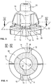
- a radial tapering of the bayonet gap 25 is preferably provided. Based on Fig. 4 it can be seen that the radial width of the bayonet gap 45 is defined by the distance S.
- the outer diameter D of the coupling part in the bayonet gap 25 is enlarged locally. This is shown by the solid line in the bayonet gap 25 in comparison to the dash-dot line, which shows a radial tapering of the bayonet gap 25 against the direction of screwing in of the coupling part 1 (see FIG Fig. 1 ).
- This radial taper can preferably take place continuously, as shown in FIG Fig. 4 is illustrated. It is also preferred to achieve this radial tapering of the bayonet gap 25 in a locally limited or punctiform manner, for example with a radially oriented projection.
- the latching gap 35 has a tapering in the axial direction in relation to the longitudinal axis L of the coupling part 1.
- a web 32 is arranged on the contact flange 50, running in the radial direction, in order to form this taper. With the help of the web 32, tolerance compensation can be achieved, for example with regard to different thicknesses of the component A.
- an inclined surface analogous to the inlet bevels 14, 18 of the bayonet gap 25 can be used instead of the web 32.
- Fig. 5 shows a perspective view of the coupling part 1 from below.
- a web-like structure 60 with radially extending sections 62 is provided adjacent to the insertion opening for the ball stud.
- the preferred web-like structure 60 makes it easier for the worker to grasp and press in the coupling part 1 in the axial direction or to engage the coupling part 1 in the keyhole 5, 7.
- it is precisely the radial sections 62 that support the rotation of the coupling part 1 in the direction of the arrow (see FIG Fig. 1 ) to establish the bayonet connection.
- the web-like structure 60 preferably comprises an orientation aid 64 for the worker.
- the orientation aid 64 shows the worker where the first radial projections 10 for producing the bayonet connection are arranged. In this way the worker can It is easier to align the first projections 30 with the bulges 7 of the keyhole 5.
- the coupling part 1 comprises an axial projection 90 which is arranged opposite the insertion opening for the ball pin (cf. Fig. 3 and 6th ).
- the axial projection 90 is used to compensate for tolerances during the installation of the coupling part 1. It is also preferred to dispense with the axial projection 90, so that the coupling part 1 is designed to be closed or open at the location of the axial projection 90.
Landscapes
- Engineering & Computer Science (AREA)
- General Engineering & Computer Science (AREA)
- Mechanical Engineering (AREA)
- Snaps, Bayonet Connections, Set Pins, And Snap Rings (AREA)
- Quick-Acting Or Multi-Walled Pipe Joints (AREA)
Claims (13)
- Élément de couplage (1) déformable élastiquement pour un assemblage par emboîtement destiné à assembler un premier composant (A) et un deuxième composant (B), présentant les caractéristiques suivantes :a. une zone d'assemblage intérieure, dans laquelle une tête (80) d'un élément du genre boulon (3) du deuxième composant (B) peut être reçue par encliquetage, et une zone de fixation extérieure apte à être assemblée avec un trou de serrure (5) du premier composant (A) par une fermeture à baïonnette, dans lequelb. la zone de fixation comporte au moins une surface d'appui radiale (50), au moins une première saillie radiale (10) étant disposée de façon axialement espacée par rapport à celle-ci, formant ainsi une fente à baïonnette (25) pour un logement rotatif du premier composant (A), et caractérisé en ce quec. au moins une deuxième saillie radiale (30) est disposée de façon axialement espacée par rapport à la surface d'appui radiale (50), laquelle forme une fente d'encliquetage (35) pour le premier composant (A) entre la deuxième saillie (30) et l'au moins une surface d'appui radiale (50) du fait d'une mobilité orientée radialement vers l'intérieur, dans lequeld. la fente à baïonnette (25) est bloquée à une longueur définie en accord avec l'agencement de la deuxième saillie radiale (30), de telle façon que lors d'une rotation de l'élément de couplage (1) autour d'un axe longitudinal (L), le premier composant (A) ne peut être retiré de la fente d'encliquetage (35) dans la région du trou de serrure (5).
- Élément de couplage (1) selon la revendication 1, dans lequel la première (10) et la deuxième saillie (30) sont disposées de façon circonférentiellement décalée l'une par rapport à l'autre.
- Élément de couplage (1) selon l'une des revendications précédentes, dans lequel la fente à baïonnette (25) est conçue de manière à se rétrécir au moins partiellement dans la direction radiale et/ou axiale de l'élément de couplage (1) afin de favoriser un maintien fiable sur le premier composant (A).
- Élément de couplage (1) selon l'une des revendications précédentes, dans lequel la fente d'encliquetage (35) est conçue de manière à se rétrécir au moins partiellement dans la direction axiale par rapport à l'élément de couplage (1).
- Élément de couplage (1) selon l'une des revendications précédentes, dans lequel il est prévu une structure du genre nervure (60) adjacente à une ouverture d'insertion de l'élément du genre boulon (3), avec laquelle l'élément de couplage (1) peut être inséré dans le trou de serrure (5), de préférence par vissage ou par encliquetage.
- Élément de couplage (1) selon l'une des revendications précédentes, dans lequel l'au moins une surface d'appui radiale (50) est formée par une bride d'appui (50) circonférentielle et associée.
- Élément de couplage (1) selon la revendication 6, dans lequel la bride d'appui (50) est conçue comme une lèvre d'étanchéité recouvrant entièrement le trou de serrure (5) du fait de son extension radiale.
- Élément de couplage (1) selon l'une des revendications précédentes, lequel est constitué d'une matière plastique élastique ou de métal.
- Système de couplage par emboîtement comportant un élément de couplage (1) selon l'une des revendications précédentes, ainsi qu'un élément du genre boulon (3) avec une tête (80).
- Composant (B) comprenant un élément du genre boulon (3) et une tête (80), lequel est assemblé avec un autre composant (A) par le biais d'un élément de couplage (1) selon l'une des revendications 1 à 8, lequel est disposé dans un trou de serrure (5) de l'autre composant (A).
- Procédé de montage d'un élément de couplage (1) selon l'une des revendications 1 à 8 dans un trou de serrure (5) d'un composant (A), comportant les étapes suivantes :a. orientation de l'élément de couplage (1) vers le trou de serrure (5), de telle façon que l'au moins une première saillie radiale (10) est disposée en face d'un renflement en forme de nervure (7) du trou de serrure (5),b. insertion de l'élément de couplage (1) dans le trou de serrure (5) dans la direction axiale et compression simultanée de l'élément de couplage (1) dans une direction radiale, afin d'encliqueter le premier composant (A) dans la fente d'encliquetage (35), etc. rotation de l'élément de couplage (1) autour de l'axe longitudinal (L) de manière à fixer le premier composant (A) dans la fente à baïonnette (25).
- Procédé de montage selon la revendication 11, dans lequel l'élément de couplage (1) est inséré dans le trou de serrure (5) dans la direction axiale jusqu'à ce que l'au moins une surface d'appui radiale (50), de préférence la bride d'appui circonférentielle (50), s'appuie sur le composant (A).
- Procédé de montage selon la revendication 11 ou 12, dans lequel une structure du genre nervure (60) est utilisée à proximité d'une ouverture d'insertion destinée à un élément du genre boulon (3) pour la rotation de l'élément de couplage (1) autour de l'axe longitudinal (L).
Applications Claiming Priority (2)
| Application Number | Priority Date | Filing Date | Title |
|---|---|---|---|
| DE202013005336.4U DE202013005336U1 (de) | 2013-06-12 | 2013-06-12 | Steckkupplung mit einem elastisch verformbaren Kupplungsteil |
| PCT/EP2014/061265 WO2014198562A1 (fr) | 2013-06-12 | 2014-05-30 | Système de couplage par emboîtement comportant un élément de couplage déformable élastiquement ainsi que procédé de montage associé |
Publications (2)
| Publication Number | Publication Date |
|---|---|
| EP3008352A1 EP3008352A1 (fr) | 2016-04-20 |
| EP3008352B1 true EP3008352B1 (fr) | 2021-09-01 |
Family
ID=50877283
Family Applications (1)
| Application Number | Title | Priority Date | Filing Date |
|---|---|---|---|
| EP14727500.2A Active EP3008352B1 (fr) | 2013-06-12 | 2014-05-30 | Système de couplage par emboîtement comportant un élément de couplage déformable élastiquement ainsi que procédé de montage associé |
Country Status (4)
| Country | Link |
|---|---|
| US (1) | US10167890B2 (fr) |
| EP (1) | EP3008352B1 (fr) |
| DE (1) | DE202013005336U1 (fr) |
| WO (1) | WO2014198562A1 (fr) |
Families Citing this family (20)
| Publication number | Priority date | Publication date | Assignee | Title |
|---|---|---|---|---|
| WO2016193232A1 (fr) * | 2015-05-30 | 2016-12-08 | Charlotte Baur Formschaumtechnik GmbH | Élément en plastique pourvu de parties de fixation |
| FR3048742B1 (fr) * | 2016-03-14 | 2018-07-13 | Peugeot Citroen Automobiles Sa | Dispositif de pre-maintien d’un element sur un support. |
| DE102016216422A1 (de) * | 2016-08-31 | 2018-03-01 | Fidlock Gmbh | Verschlussvorrichtung zum Verbinden eines Behälters z.B. an einem Fahrrad |
| US10131290B2 (en) | 2017-01-26 | 2018-11-20 | Toyota Motor Engineering & Manufacturing North America, Inc. | Removable and serviceable twist lock assembly clip for blind installation |
| FR3071567B1 (fr) * | 2017-09-27 | 2020-08-07 | Soc D'outillage Et De Caoutchouc Pour Applications Techniques | Dispositif de fixation antivibratoire |
| DE202018100986U1 (de) | 2018-02-22 | 2019-05-23 | Böllhoff Verbindungstechnik GmbH | Weibliches Kupplungsteil und dazugehörige Steckkupplung |
| FR3082899B1 (fr) * | 2018-06-21 | 2020-11-27 | Psa Automobiles Sa | Ensemble comprenant deux elements relies entre eux par un dispositif de fixation. |
| DE102018120105B4 (de) * | 2018-08-17 | 2023-02-16 | Nidec Gpm Gmbh | Dämpfungselement mit Bajonettverschluss |
| FR3085650B1 (fr) * | 2018-09-10 | 2020-09-04 | Valeo Systemes Dessuyage | Ensemble pour le liaison articulee d'une bielle et d'un maneton d'un mecanisme d'essuyage de vitre de vehicule automobile |
| JP6800190B2 (ja) * | 2018-09-20 | 2020-12-16 | 住友理工株式会社 | カバー装着用グロメット及びカバー |
| CN112049850A (zh) * | 2019-06-06 | 2020-12-08 | 伊利诺斯工具制品有限公司 | 紧固件 |
| US11277927B2 (en) * | 2019-11-05 | 2022-03-15 | Lear Corporation | System and method for mounting an electronics arrangement |
| ES2831097B2 (es) * | 2019-12-05 | 2022-10-17 | Seat Sa | Dispositivo de acoplamiento |
| FR3107738B1 (fr) * | 2020-03-02 | 2022-07-08 | Valeo Systemes Dessuyage | Support de boîte à rotule, bielle et procédé d’assemblage correspondants |
| US12473941B2 (en) | 2020-08-07 | 2025-11-18 | Peri Se | Multi-head bolt and fastener system |
| US11788571B2 (en) | 2020-08-07 | 2023-10-17 | Peri Se | Multi-head bolt and fastener system |
| DE102021001649A1 (de) | 2021-03-29 | 2022-09-29 | Mercedes-Benz Group AG | Befestigungseinrichtung zum Befestigen eines ersten Bauteils an einem zweiten Bauteil, insbesondere für ein Kraftfahrzeug |
| CN114576292B (zh) * | 2022-05-05 | 2022-07-26 | 江苏凯途液压传动机械科技有限公司 | 一种便于拆装的湿式制动器 |
| CN118399118B (zh) * | 2024-06-20 | 2024-09-17 | 广州伟仕达电子科技有限公司 | 一种具有散温功能的车载充电器 |
| EP4686837A1 (fr) * | 2024-07-31 | 2026-02-04 | Volvo Truck Corporation | Connecteur rotatif pour la fixation mécanique d'un dispositif à une structure de support par un goujon de fixation, et système de connexion, agencement de fixation et procédé avec un tel connecteur |
Family Cites Families (30)
| Publication number | Priority date | Publication date | Assignee | Title |
|---|---|---|---|---|
| US580204A (en) | 1897-04-06 | Body-bolster for cars | ||
| US2610879A (en) * | 1949-08-23 | 1952-09-16 | A Kimball Co | Lock seal suitable for manufacture in plastics |
| US3749431A (en) * | 1971-04-08 | 1973-07-31 | Rau Swf Autozubehoer | Universal joint construction |
| US3853414A (en) * | 1972-04-25 | 1974-12-10 | Jidosha Denki Kogyo Kk | Ball joint apparatus |
| IT959691B (it) * | 1972-05-05 | 1973-11-10 | Magneti Marelli Spa | Giunto snodato per aste in genere particolarmente per tergicristallo di autoveicoli |
| US3856422A (en) * | 1973-05-29 | 1974-12-24 | W Trefry | Retention clip for ball and socket joint |
| US4266883A (en) * | 1979-04-16 | 1981-05-12 | Trico Products Corporation | Windshield wiper linkage |
| US4552480A (en) * | 1984-06-29 | 1985-11-12 | Sprague Devices, Inc. | Ball joint structure |
| FR2608233B1 (fr) * | 1986-12-15 | 1989-03-31 | Marchal Equip Auto | Ensemble constitue d'un organe femelle pour une articulation a rotule, et d'une piece, notamment une bielle, organe femelle et piece pour un tel ensemble |
| US4750886A (en) * | 1987-11-04 | 1988-06-14 | General Motors Corporation | Rod and retainer bushing |
| US4993863A (en) * | 1988-04-29 | 1991-02-19 | Mitsuba Electric Mfg. Co., Ltd. | Joint device |
| JP2727454B2 (ja) * | 1988-06-28 | 1998-03-11 | 株式会社ニフコ | 板の結合クリップ |
| IT214905Z2 (it) | 1988-11-15 | 1990-07-04 | Carello Spa | Accoppiamento sferico smontabile |
| FR2648411B1 (fr) * | 1989-06-15 | 1994-10-07 | Valeo Systemes Dessuyage | Joint d'articulation a rotule notamment pour tringlerie d'essuie-glace de vehicule automobile |
| US5013175A (en) * | 1989-10-10 | 1991-05-07 | Ford Motor Company | Windshield wiper anti-roll connector |
| US5580204A (en) | 1995-03-07 | 1996-12-03 | Textron Inc. | Panel attachment system |
| ES2191234T3 (es) | 1997-09-12 | 2003-09-01 | Bollhoff Gmbh | Acoplamiento por enchufe. |
| DE19833665A1 (de) * | 1998-07-27 | 2000-02-03 | Bosch Gmbh Robert | Vorrichtung zum Verbinden eines Wischblatts für Scheiben von Kraftfahrzeugen mit einem am Kraftfahrzeug einendig geführten, angetriebenen Wischerarm |
| DE19838560B4 (de) | 1998-08-25 | 2006-04-13 | Lisa Dräxlmaier GmbH | Drehschnellverschluß zum miteinander Verbinden mehrerer Bauteile |
| DE202005011420U1 (de) | 2005-07-20 | 2005-10-13 | Böllhoff Verbindungstechnik GmbH | Steckkupplung mit dreidimensionaler Ausgleichsbewegung in Plattenmontage |
| FR2894304A1 (fr) | 2005-12-05 | 2007-06-08 | Raymond Et Cie Soc En Commandi | Dispositif d'assemblage de deux plaques |
| DE102006020697B3 (de) | 2006-05-04 | 2007-04-26 | A. Raymond Et Cie | Drehverschluss |
| EP2198171A4 (fr) * | 2007-08-29 | 2010-10-13 | Tinnerman Palnut Engineered Pr | Agrafe de garnissage |
| DE102008033307A1 (de) * | 2008-07-16 | 2010-01-21 | Newfrey Llc, Newark | Befestigungsvorrichtung |
| JP2010053993A (ja) * | 2008-08-29 | 2010-03-11 | Daiwa Kasei Kogyo Kk | 二部材組付け構造 |
| DE102008061613A1 (de) * | 2008-12-11 | 2010-07-01 | Trw Automotive Electronics & Components Gmbh | Vorrichtung zur Befestigung einer Fahrzeuginnenverkleidung |
| DE112008004188B4 (de) * | 2008-12-19 | 2014-03-20 | Toyota Jidosha Kabushiki Kaisha | Befestigungsstruktur mit einer Durchgangstülle |
| EP2495456A4 (fr) * | 2009-10-29 | 2013-05-22 | Yachiyo Ind Co Ltd | Structure d'assemblage de composant et écrou à douille |
| DE102010030964A1 (de) * | 2010-07-06 | 2012-01-12 | Bayerische Motoren Werke Aktiengesellschaft | Befestigungsanordnung zum Befestigen von Kraftfahrzeugbauteilen |
| DE102011052190A1 (de) * | 2011-07-27 | 2013-01-31 | Böllhoff Verbindungstechnik GmbH | Steckkupplung und Verfahren zu ihrer Herstellung |
-
2013
- 2013-06-12 DE DE202013005336.4U patent/DE202013005336U1/de not_active Expired - Lifetime
-
2014
- 2014-05-30 US US14/897,490 patent/US10167890B2/en active Active
- 2014-05-30 WO PCT/EP2014/061265 patent/WO2014198562A1/fr not_active Ceased
- 2014-05-30 EP EP14727500.2A patent/EP3008352B1/fr active Active
Also Published As
| Publication number | Publication date |
|---|---|
| DE202013005336U1 (de) | 2014-07-14 |
| EP3008352A1 (fr) | 2016-04-20 |
| US10167890B2 (en) | 2019-01-01 |
| US20160108950A1 (en) | 2016-04-21 |
| WO2014198562A1 (fr) | 2014-12-18 |
Similar Documents
| Publication | Publication Date | Title |
|---|---|---|
| EP3008352B1 (fr) | Système de couplage par emboîtement comportant un élément de couplage déformable élastiquement ainsi que procédé de montage associé | |
| EP2318723B1 (fr) | Agencement de fixation avec compensation des tolerances | |
| DE102007037242B4 (de) | Befestigungseinrichtung mit Toleranzausgleich | |
| DE19654848C2 (de) | Montageteil mit schwingungsgedämpftem Befestigungsloch | |
| EP3209888B1 (fr) | Dispositif de fixation rapide, procédé d'assemblage de deux éléments au moyen du dispositif de fixation rapide, et procédé de fabrication afférent | |
| DE19930728B4 (de) | Dübel zum Befestigen eines Gegenstandes an einem Träger aus Flachmaterial | |
| EP3612740B1 (fr) | Unité de réglage et procédé de réglage d'un composant | |
| EP3329132B1 (fr) | Accouplement emboîtable en deux parties servant à l'assemblage de pièces | |
| EP4048908B1 (fr) | Élément de connexion et agencement de connexion | |
| EP1065426A2 (fr) | Dispositif de raccordement pour la fixation d'objets allongés | |
| EP3021974A1 (fr) | Centrifugeuse | |
| DE102010024870A1 (de) | Vorrichtung zum Befestigen eines Bauteils an einem Befestigungsbolzen | |
| DE102012208084B3 (de) | Anlenk-Vorrichtung zum Anlenken eines Reibungs-Dämpfers an eine Waschmaschine | |
| DE102010008040A1 (de) | Vorrichtung zur lösbaren Verbindung zweier Bauteile | |
| EP2980425A1 (fr) | Agencement de fixation pour rails de retenue en forme de c et kit | |
| DE102018101944A1 (de) | Unlösbare Befestigungsvorrichtung | |
| EP2581637B1 (fr) | Couvercle de fermeture destiné à fermer un orifice de contrôle sur un tuyau d'échappement en matière synthétique, tuyau d'échappement et système avec un couvercle de fermeture | |
| EP3736464B1 (fr) | Entretoise pour un agencement de fixation, agencement de fixation doté d'une telle entretoise ainsi que procédé de fixation d'une pièce de montage sur une pièce de support | |
| EP2304250A1 (fr) | Clip à vis | |
| DE102021103968B3 (de) | Montage-Einheit mit zumindest einer Montageschiene sowie wenigstens einer Halteklammer | |
| DE202006015982U1 (de) | Verriegelbare Steckkupplung | |
| DE102006030769B3 (de) | Vorrichtung zur Aufnahme eines Kraftfahrzeug-Wagenhebers | |
| EP0791759A1 (fr) | Boulon à connexion rapide | |
| DE102023103194A1 (de) | Verbindungselement zweier zueinander beabstandeter Bauteile mit Toleranzausgleichsfunktion sowie ein Installationsverfahren dafür | |
| DE602004000592T2 (de) | Verbindungsvorrichtung für ein Steuerkabelende |
Legal Events
| Date | Code | Title | Description |
|---|---|---|---|
| PUAI | Public reference made under article 153(3) epc to a published international application that has entered the european phase |
Free format text: ORIGINAL CODE: 0009012 |
|
| 17P | Request for examination filed |
Effective date: 20151119 |
|
| AK | Designated contracting states |
Kind code of ref document: A1 Designated state(s): AL AT BE BG CH CY CZ DE DK EE ES FI FR GB GR HR HU IE IS IT LI LT LU LV MC MK MT NL NO PL PT RO RS SE SI SK SM TR |
|
| AX | Request for extension of the european patent |
Extension state: BA ME |
|
| DAX | Request for extension of the european patent (deleted) | ||
| STAA | Information on the status of an ep patent application or granted ep patent |
Free format text: STATUS: EXAMINATION IS IN PROGRESS |
|
| 17Q | First examination report despatched |
Effective date: 20170116 |
|
| GRAP | Despatch of communication of intention to grant a patent |
Free format text: ORIGINAL CODE: EPIDOSNIGR1 |
|
| STAA | Information on the status of an ep patent application or granted ep patent |
Free format text: STATUS: GRANT OF PATENT IS INTENDED |
|
| RIC1 | Information provided on ipc code assigned before grant |
Ipc: F16B 21/04 20060101ALI20210310BHEP Ipc: F16B 21/07 20060101AFI20210310BHEP |
|
| INTG | Intention to grant announced |
Effective date: 20210409 |
|
| GRAS | Grant fee paid |
Free format text: ORIGINAL CODE: EPIDOSNIGR3 |
|
| GRAA | (expected) grant |
Free format text: ORIGINAL CODE: 0009210 |
|
| STAA | Information on the status of an ep patent application or granted ep patent |
Free format text: STATUS: THE PATENT HAS BEEN GRANTED |
|
| AK | Designated contracting states |
Kind code of ref document: B1 Designated state(s): AL AT BE BG CH CY CZ DE DK EE ES FI FR GB GR HR HU IE IS IT LI LT LU LV MC MK MT NL NO PL PT RO RS SE SI SK SM TR |
|
| REG | Reference to a national code |
Ref country code: GB Ref legal event code: FG4D Free format text: NOT ENGLISH |
|
| REG | Reference to a national code |
Ref country code: CH Ref legal event code: EP Ref country code: AT Ref legal event code: REF Ref document number: 1426539 Country of ref document: AT Kind code of ref document: T Effective date: 20210915 |
|
| REG | Reference to a national code |
Ref country code: DE Ref legal event code: R096 Ref document number: 502014015845 Country of ref document: DE |
|
| REG | Reference to a national code |
Ref country code: IE Ref legal event code: FG4D Free format text: LANGUAGE OF EP DOCUMENT: GERMAN |
|
| REG | Reference to a national code |
Ref country code: LT Ref legal event code: MG9D |
|
| REG | Reference to a national code |
Ref country code: NL Ref legal event code: MP Effective date: 20210901 |
|
| PG25 | Lapsed in a contracting state [announced via postgrant information from national office to epo] |
Ref country code: HR Free format text: LAPSE BECAUSE OF FAILURE TO SUBMIT A TRANSLATION OF THE DESCRIPTION OR TO PAY THE FEE WITHIN THE PRESCRIBED TIME-LIMIT Effective date: 20210901 Ref country code: RS Free format text: LAPSE BECAUSE OF FAILURE TO SUBMIT A TRANSLATION OF THE DESCRIPTION OR TO PAY THE FEE WITHIN THE PRESCRIBED TIME-LIMIT Effective date: 20210901 Ref country code: SE Free format text: LAPSE BECAUSE OF FAILURE TO SUBMIT A TRANSLATION OF THE DESCRIPTION OR TO PAY THE FEE WITHIN THE PRESCRIBED TIME-LIMIT Effective date: 20210901 Ref country code: FI Free format text: LAPSE BECAUSE OF FAILURE TO SUBMIT A TRANSLATION OF THE DESCRIPTION OR TO PAY THE FEE WITHIN THE PRESCRIBED TIME-LIMIT Effective date: 20210901 Ref country code: ES Free format text: LAPSE BECAUSE OF FAILURE TO SUBMIT A TRANSLATION OF THE DESCRIPTION OR TO PAY THE FEE WITHIN THE PRESCRIBED TIME-LIMIT Effective date: 20210901 Ref country code: NO Free format text: LAPSE BECAUSE OF FAILURE TO SUBMIT A TRANSLATION OF THE DESCRIPTION OR TO PAY THE FEE WITHIN THE PRESCRIBED TIME-LIMIT Effective date: 20211201 Ref country code: LT Free format text: LAPSE BECAUSE OF FAILURE TO SUBMIT A TRANSLATION OF THE DESCRIPTION OR TO PAY THE FEE WITHIN THE PRESCRIBED TIME-LIMIT Effective date: 20210901 Ref country code: BG Free format text: LAPSE BECAUSE OF FAILURE TO SUBMIT A TRANSLATION OF THE DESCRIPTION OR TO PAY THE FEE WITHIN THE PRESCRIBED TIME-LIMIT Effective date: 20211201 |
|
| PG25 | Lapsed in a contracting state [announced via postgrant information from national office to epo] |
Ref country code: PL Free format text: LAPSE BECAUSE OF FAILURE TO SUBMIT A TRANSLATION OF THE DESCRIPTION OR TO PAY THE FEE WITHIN THE PRESCRIBED TIME-LIMIT Effective date: 20210901 Ref country code: LV Free format text: LAPSE BECAUSE OF FAILURE TO SUBMIT A TRANSLATION OF THE DESCRIPTION OR TO PAY THE FEE WITHIN THE PRESCRIBED TIME-LIMIT Effective date: 20210901 Ref country code: GR Free format text: LAPSE BECAUSE OF FAILURE TO SUBMIT A TRANSLATION OF THE DESCRIPTION OR TO PAY THE FEE WITHIN THE PRESCRIBED TIME-LIMIT Effective date: 20211202 |
|
| PG25 | Lapsed in a contracting state [announced via postgrant information from national office to epo] |
Ref country code: IS Free format text: LAPSE BECAUSE OF FAILURE TO SUBMIT A TRANSLATION OF THE DESCRIPTION OR TO PAY THE FEE WITHIN THE PRESCRIBED TIME-LIMIT Effective date: 20220101 Ref country code: SM Free format text: LAPSE BECAUSE OF FAILURE TO SUBMIT A TRANSLATION OF THE DESCRIPTION OR TO PAY THE FEE WITHIN THE PRESCRIBED TIME-LIMIT Effective date: 20210901 Ref country code: SK Free format text: LAPSE BECAUSE OF FAILURE TO SUBMIT A TRANSLATION OF THE DESCRIPTION OR TO PAY THE FEE WITHIN THE PRESCRIBED TIME-LIMIT Effective date: 20210901 Ref country code: RO Free format text: LAPSE BECAUSE OF FAILURE TO SUBMIT A TRANSLATION OF THE DESCRIPTION OR TO PAY THE FEE WITHIN THE PRESCRIBED TIME-LIMIT Effective date: 20210901 Ref country code: PT Free format text: LAPSE BECAUSE OF FAILURE TO SUBMIT A TRANSLATION OF THE DESCRIPTION OR TO PAY THE FEE WITHIN THE PRESCRIBED TIME-LIMIT Effective date: 20220103 Ref country code: NL Free format text: LAPSE BECAUSE OF FAILURE TO SUBMIT A TRANSLATION OF THE DESCRIPTION OR TO PAY THE FEE WITHIN THE PRESCRIBED TIME-LIMIT Effective date: 20210901 Ref country code: EE Free format text: LAPSE BECAUSE OF FAILURE TO SUBMIT A TRANSLATION OF THE DESCRIPTION OR TO PAY THE FEE WITHIN THE PRESCRIBED TIME-LIMIT Effective date: 20210901 Ref country code: CZ Free format text: LAPSE BECAUSE OF FAILURE TO SUBMIT A TRANSLATION OF THE DESCRIPTION OR TO PAY THE FEE WITHIN THE PRESCRIBED TIME-LIMIT Effective date: 20210901 Ref country code: AL Free format text: LAPSE BECAUSE OF FAILURE TO SUBMIT A TRANSLATION OF THE DESCRIPTION OR TO PAY THE FEE WITHIN THE PRESCRIBED TIME-LIMIT Effective date: 20210901 |
|
| REG | Reference to a national code |
Ref country code: DE Ref legal event code: R097 Ref document number: 502014015845 Country of ref document: DE |
|
| PLBE | No opposition filed within time limit |
Free format text: ORIGINAL CODE: 0009261 |
|
| STAA | Information on the status of an ep patent application or granted ep patent |
Free format text: STATUS: NO OPPOSITION FILED WITHIN TIME LIMIT |
|
| PG25 | Lapsed in a contracting state [announced via postgrant information from national office to epo] |
Ref country code: IT Free format text: LAPSE BECAUSE OF FAILURE TO SUBMIT A TRANSLATION OF THE DESCRIPTION OR TO PAY THE FEE WITHIN THE PRESCRIBED TIME-LIMIT Effective date: 20210901 Ref country code: DK Free format text: LAPSE BECAUSE OF FAILURE TO SUBMIT A TRANSLATION OF THE DESCRIPTION OR TO PAY THE FEE WITHIN THE PRESCRIBED TIME-LIMIT Effective date: 20210901 |
|
| 26N | No opposition filed |
Effective date: 20220602 |
|
| PG25 | Lapsed in a contracting state [announced via postgrant information from national office to epo] |
Ref country code: SI Free format text: LAPSE BECAUSE OF FAILURE TO SUBMIT A TRANSLATION OF THE DESCRIPTION OR TO PAY THE FEE WITHIN THE PRESCRIBED TIME-LIMIT Effective date: 20210901 |
|
| REG | Reference to a national code |
Ref country code: CH Ref legal event code: PL |
|
| REG | Reference to a national code |
Ref country code: BE Ref legal event code: MM Effective date: 20220531 |
|
| PG25 | Lapsed in a contracting state [announced via postgrant information from national office to epo] |
Ref country code: MC Free format text: LAPSE BECAUSE OF FAILURE TO SUBMIT A TRANSLATION OF THE DESCRIPTION OR TO PAY THE FEE WITHIN THE PRESCRIBED TIME-LIMIT Effective date: 20210901 Ref country code: LU Free format text: LAPSE BECAUSE OF NON-PAYMENT OF DUE FEES Effective date: 20220530 Ref country code: LI Free format text: LAPSE BECAUSE OF NON-PAYMENT OF DUE FEES Effective date: 20220531 Ref country code: CH Free format text: LAPSE BECAUSE OF NON-PAYMENT OF DUE FEES Effective date: 20220531 |
|
| PG25 | Lapsed in a contracting state [announced via postgrant information from national office to epo] |
Ref country code: IE Free format text: LAPSE BECAUSE OF NON-PAYMENT OF DUE FEES Effective date: 20220530 |
|
| PG25 | Lapsed in a contracting state [announced via postgrant information from national office to epo] |
Ref country code: BE Free format text: LAPSE BECAUSE OF NON-PAYMENT OF DUE FEES Effective date: 20220531 |
|
| REG | Reference to a national code |
Ref country code: AT Ref legal event code: MM01 Ref document number: 1426539 Country of ref document: AT Kind code of ref document: T Effective date: 20220530 |
|
| PG25 | Lapsed in a contracting state [announced via postgrant information from national office to epo] |
Ref country code: AT Free format text: LAPSE BECAUSE OF NON-PAYMENT OF DUE FEES Effective date: 20220530 |
|
| PG25 | Lapsed in a contracting state [announced via postgrant information from national office to epo] |
Ref country code: HU Free format text: LAPSE BECAUSE OF FAILURE TO SUBMIT A TRANSLATION OF THE DESCRIPTION OR TO PAY THE FEE WITHIN THE PRESCRIBED TIME-LIMIT; INVALID AB INITIO Effective date: 20140530 |
|
| PG25 | Lapsed in a contracting state [announced via postgrant information from national office to epo] |
Ref country code: MK Free format text: LAPSE BECAUSE OF FAILURE TO SUBMIT A TRANSLATION OF THE DESCRIPTION OR TO PAY THE FEE WITHIN THE PRESCRIBED TIME-LIMIT Effective date: 20210901 Ref country code: CY Free format text: LAPSE BECAUSE OF FAILURE TO SUBMIT A TRANSLATION OF THE DESCRIPTION OR TO PAY THE FEE WITHIN THE PRESCRIBED TIME-LIMIT Effective date: 20210901 |
|
| PG25 | Lapsed in a contracting state [announced via postgrant information from national office to epo] |
Ref country code: MT Free format text: LAPSE BECAUSE OF FAILURE TO SUBMIT A TRANSLATION OF THE DESCRIPTION OR TO PAY THE FEE WITHIN THE PRESCRIBED TIME-LIMIT Effective date: 20210901 |
|
| PGFP | Annual fee paid to national office [announced via postgrant information from national office to epo] |
Ref country code: GB Payment date: 20250522 Year of fee payment: 12 |
|
| PGFP | Annual fee paid to national office [announced via postgrant information from national office to epo] |
Ref country code: FR Payment date: 20250521 Year of fee payment: 12 |
|
| PGFP | Annual fee paid to national office [announced via postgrant information from national office to epo] |
Ref country code: DE Payment date: 20250730 Year of fee payment: 12 |
|
| PG25 | Lapsed in a contracting state [announced via postgrant information from national office to epo] |
Ref country code: TR Free format text: LAPSE BECAUSE OF FAILURE TO SUBMIT A TRANSLATION OF THE DESCRIPTION OR TO PAY THE FEE WITHIN THE PRESCRIBED TIME-LIMIT Effective date: 20210901 |