EP3008367B1 - Robinet d'isolement et clapet anti-retour combinés à mesure intégrée du débit, de la pression et/ou de la température - Google Patents
Robinet d'isolement et clapet anti-retour combinés à mesure intégrée du débit, de la pression et/ou de la température Download PDFInfo
- Publication number
- EP3008367B1 EP3008367B1 EP14810277.5A EP14810277A EP3008367B1 EP 3008367 B1 EP3008367 B1 EP 3008367B1 EP 14810277 A EP14810277 A EP 14810277A EP 3008367 B1 EP3008367 B1 EP 3008367B1
- Authority
- EP
- European Patent Office
- Prior art keywords
- signaling
- sensor
- valve
- combination valve
- pump
- Prior art date
- Legal status (The legal status is an assumption and is not a legal conclusion. Google has not performed a legal analysis and makes no representation as to the accuracy of the status listed.)
- Active
Links
- 238000002955 isolation Methods 0.000 title claims description 15
- 238000009529 body temperature measurement Methods 0.000 title claims description 13
- 230000011664 signaling Effects 0.000 claims description 46
- 238000005259 measurement Methods 0.000 claims description 38
- 230000005540 biological transmission Effects 0.000 claims description 27
- 239000012530 fluid Substances 0.000 claims description 25
- 238000009530 blood pressure measurement Methods 0.000 claims description 10
- 230000005484 gravity Effects 0.000 claims description 4
- 238000004378 air conditioning Methods 0.000 claims description 2
- 239000002131 composite material Substances 0.000 claims description 2
- 238000010438 heat treatment Methods 0.000 claims description 2
- 238000009423 ventilation Methods 0.000 claims description 2
- 238000012545 processing Methods 0.000 description 3
- 238000004590 computer program Methods 0.000 description 2
- 238000010586 diagram Methods 0.000 description 2
- 238000005516 engineering process Methods 0.000 description 2
- 238000000034 method Methods 0.000 description 2
- 239000000523 sample Substances 0.000 description 2
- 238000013461 design Methods 0.000 description 1
- 238000011156 evaluation Methods 0.000 description 1
- 238000012423 maintenance Methods 0.000 description 1
- XLYOFNOQVPJJNP-UHFFFAOYSA-N water Substances O XLYOFNOQVPJJNP-UHFFFAOYSA-N 0.000 description 1
Images
Classifications
-
- F—MECHANICAL ENGINEERING; LIGHTING; HEATING; WEAPONS; BLASTING
- F16—ENGINEERING ELEMENTS AND UNITS; GENERAL MEASURES FOR PRODUCING AND MAINTAINING EFFECTIVE FUNCTIONING OF MACHINES OR INSTALLATIONS; THERMAL INSULATION IN GENERAL
- F16K—VALVES; TAPS; COCKS; ACTUATING-FLOATS; DEVICES FOR VENTING OR AERATING
- F16K37/00—Special means in or on valves or other cut-off apparatus for indicating or recording operation thereof, or for enabling an alarm to be given
- F16K37/0025—Electrical or magnetic means
-
- G—PHYSICS
- G01—MEASURING; TESTING
- G01K—MEASURING TEMPERATURE; MEASURING QUANTITY OF HEAT; THERMALLY-SENSITIVE ELEMENTS NOT OTHERWISE PROVIDED FOR
- G01K13/00—Thermometers specially adapted for specific purposes
- G01K13/02—Thermometers specially adapted for specific purposes for measuring temperature of moving fluids or granular materials capable of flow
-
- F—MECHANICAL ENGINEERING; LIGHTING; HEATING; WEAPONS; BLASTING
- F16—ENGINEERING ELEMENTS AND UNITS; GENERAL MEASURES FOR PRODUCING AND MAINTAINING EFFECTIVE FUNCTIONING OF MACHINES OR INSTALLATIONS; THERMAL INSULATION IN GENERAL
- F16K—VALVES; TAPS; COCKS; ACTUATING-FLOATS; DEVICES FOR VENTING OR AERATING
- F16K17/00—Safety valves; Equalising valves, e.g. pressure relief valves
- F16K17/003—Safety valves; Equalising valves, e.g. pressure relief valves reacting to pressure and temperature
-
- F—MECHANICAL ENGINEERING; LIGHTING; HEATING; WEAPONS; BLASTING
- F16—ENGINEERING ELEMENTS AND UNITS; GENERAL MEASURES FOR PRODUCING AND MAINTAINING EFFECTIVE FUNCTIONING OF MACHINES OR INSTALLATIONS; THERMAL INSULATION IN GENERAL
- F16K—VALVES; TAPS; COCKS; ACTUATING-FLOATS; DEVICES FOR VENTING OR AERATING
- F16K37/00—Special means in or on valves or other cut-off apparatus for indicating or recording operation thereof, or for enabling an alarm to be given
- F16K37/0025—Electrical or magnetic means
- F16K37/005—Electrical or magnetic means for measuring fluid parameters
-
- F—MECHANICAL ENGINEERING; LIGHTING; HEATING; WEAPONS; BLASTING
- F16—ENGINEERING ELEMENTS AND UNITS; GENERAL MEASURES FOR PRODUCING AND MAINTAINING EFFECTIVE FUNCTIONING OF MACHINES OR INSTALLATIONS; THERMAL INSULATION IN GENERAL
- F16K—VALVES; TAPS; COCKS; ACTUATING-FLOATS; DEVICES FOR VENTING OR AERATING
- F16K37/00—Special means in or on valves or other cut-off apparatus for indicating or recording operation thereof, or for enabling an alarm to be given
- F16K37/0075—For recording or indicating the functioning of a valve in combination with test equipment
- F16K37/0091—For recording or indicating the functioning of a valve in combination with test equipment by measuring fluid parameters
-
- F—MECHANICAL ENGINEERING; LIGHTING; HEATING; WEAPONS; BLASTING
- F24—HEATING; RANGES; VENTILATING
- F24D—DOMESTIC- OR SPACE-HEATING SYSTEMS, e.g. CENTRAL HEATING SYSTEMS; DOMESTIC HOT-WATER SUPPLY SYSTEMS; ELEMENTS OR COMPONENTS THEREFOR
- F24D3/00—Hot-water central heating systems
- F24D3/10—Feed-line arrangements, e.g. providing for heat-accumulator tanks, expansion tanks ; Hydraulic components of a central heating system
- F24D3/1083—Filling valves or arrangements for filling
-
- G—PHYSICS
- G01—MEASURING; TESTING
- G01F—MEASURING VOLUME, VOLUME FLOW, MASS FLOW OR LIQUID LEVEL; METERING BY VOLUME
- G01F1/00—Measuring the volume flow or mass flow of fluid or fluent solid material wherein the fluid passes through a meter in a continuous flow
-
- G—PHYSICS
- G01—MEASURING; TESTING
- G01F—MEASURING VOLUME, VOLUME FLOW, MASS FLOW OR LIQUID LEVEL; METERING BY VOLUME
- G01F15/00—Details of, or accessories for, apparatus of groups G01F1/00 - G01F13/00 insofar as such details or appliances are not adapted to particular types of such apparatus
- G01F15/005—Valves
-
- G—PHYSICS
- G01—MEASURING; TESTING
- G01F—MEASURING VOLUME, VOLUME FLOW, MASS FLOW OR LIQUID LEVEL; METERING BY VOLUME
- G01F15/00—Details of, or accessories for, apparatus of groups G01F1/00 - G01F13/00 insofar as such details or appliances are not adapted to particular types of such apparatus
- G01F15/06—Indicating or recording devices
- G01F15/061—Indicating or recording devices for remote indication
- G01F15/063—Indicating or recording devices for remote indication using electrical means
-
- G—PHYSICS
- G01—MEASURING; TESTING
- G01K—MEASURING TEMPERATURE; MEASURING QUANTITY OF HEAT; THERMALLY-SENSITIVE ELEMENTS NOT OTHERWISE PROVIDED FOR
- G01K2201/00—Application of thermometers in air-conditioning systems
-
- Y—GENERAL TAGGING OF NEW TECHNOLOGICAL DEVELOPMENTS; GENERAL TAGGING OF CROSS-SECTIONAL TECHNOLOGIES SPANNING OVER SEVERAL SECTIONS OF THE IPC; TECHNICAL SUBJECTS COVERED BY FORMER USPC CROSS-REFERENCE ART COLLECTIONS [XRACs] AND DIGESTS
- Y10—TECHNICAL SUBJECTS COVERED BY FORMER USPC
- Y10T—TECHNICAL SUBJECTS COVERED BY FORMER US CLASSIFICATION
- Y10T137/00—Fluid handling
- Y10T137/8593—Systems
- Y10T137/86485—Line condition change responsive release of valve
Definitions
- the present invention relates to a valve; and more particularly, relates to a combination valve for use in a hydronic HVAC system.
- HVAC heating, ventilation and air conditioning
- the present invention provides for a new and unique apparatus that features a combination valve having an isolation shutoff valve, a check valve, a pressure sensor, a temperature sensor and a flow measurement sensor.
- the isolation shutoff valve may be configured to prevent a fluid flow.
- the check valve may be configured to prevent backflow and gravity circulation of the fluid flow.
- the pressure sensor may be configured to sense to a pressure measurement of the fluid flow and determine pressure sensor signaling containing information about a sensed pressure measurement.
- the temperature sensor may be configured to sense a temperature measurement of the fluid flow and determine temperature sensor signaling containing information about a sensed temperature measurement.
- the flow measurement sensor may be configured to sense a flow measurement of the fluid flow and determine flow measurement signaling containing information about a sensed flow measurement.
- the pressure sensor, temperature sensor and flow measurement sensor are all embedded and preassembled in the combination valve with the isolation shutoff valve and the check valve as part of one integral composite unit or component, so as to form a combination isolation valve and check valve with integral flow rate, pressure and/or temperature measurement.
- the present invention may include one or more of the following additional features:
- the pressure sensor may be configured to provide the pressure sensor signaling, the temperature sensor is configured to provide the temperature sensor signaling, and the flow measurement sensor is configured to provide the flow measurement signaling; and the apparatus may further include a wireless data transmission unit or circuitry, configured to respond to the pressure sensor signaling, the temperature sensor signaling and the flow measurement signaling, and provide corresponding sensor signaling containing information about the same.
- the apparatus may further include a pump configured to provide the fluid flow to the combination valve; and a pump controller having a corresponding wireless data transmission unit or circuitry configured to respond to the corresponding signaling and provide a pump control signal to the pump in order to adjust the performance of the pump and meet desired system requirements related to the fluid flow, including where the apparatus includes an HVAC system coupled between the pump and the combination valve.
- the combination valve may be configured to provide a single head loss location.
- the wireless data transmission unit or circuitry and corresponding wireless data transmission unit or circuitry may be combined into a continuous input/output feedback loop, including where flow rate, pressure and/or temperature are inputs and pump performance parameters are desired outputs.
- the wireless data transmission unit or circuitry and corresponding wireless data transmission unit or circuitry may be configured to be paired using wireless signaling.
- the pressure sensor, temperature sensor and flow measurement sensor may be embedded into the valve combination so as to substantially eliminate the possibility of leakage, based at least partly on the fact that there are no probes inserted.
- the present invention may also take the form of a combination valve that includes an isolation shutoff configured to prevent a fluid flow, a check valve configured to prevent backflow and gravity circulation of the fluid flow, a pressure sensor configured to sense to a pressure measurement of the fluid flow and provide pressure sensor signaling containing information about a sensed pressure measurement, a temperature sensor configured to sense a temperature measurement of the fluid flow and provide temperature sensor signaling containing information about a sensed temperature measurement, and a flow measurement sensor configured to sense a flow measurement of the fluid flow and provide flow measurement signaling containing information about a sensed flow measurement; and data transmission module, configured to respond to the pressure sensor signaling, the temperature sensor signaling and the flow measurement signaling, and provide corresponding signaling containing information about the same.
- a combination valve that includes an isolation shutoff configured to prevent a fluid flow, a check valve configured to prevent backflow and gravity circulation of the fluid flow, a pressure sensor configured to sense to a pressure measurement of the fluid flow and provide pressure sensor signaling containing information about a sensed pressure measurement,
- the pressure sensor, the temperature sensor and flow measurement sensor may be hard wired to the wireless data transmission unit or circuitry for providing associated sensor signaling; or the pressure sensor, the temperature sensor and flow measurement sensor may be configured to provide the associated sensor signaling to the wireless data transmission unit or circuitry via wireless signaling; or the wireless data transmission unit or circuitry may be configured to provide the corresponding signaling via wireless signal, including to a pump controller for controlling a pump, consistent with that set forth herein.
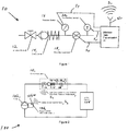
- Figure 1 shows a combination valve generally indicated as 10 that may be used in, or form part of, a hydronic HVAC system generally indicated as 100.
- the combination valve 10 may be configured to include an isolation valve 12; a check valve 14; and as a means and/or sensors 16, 18 and 20 for measuring fluid parameters, such as pressure, flow rate, and/or temperature, consistent with that shown in Figure 1 .
- the hydronic HVAC system 100 may be configured to include e.g., a pump 102, an HVAC system 104 and a pump controller 106 for controlling the operation of the pump 102.
- the present invention allows or provides for the combination valve 10 in the hydronic HVAC system 100 to function as a combined isolation valve; a check valve; and as a means for measuring fluid parameters, such as flow rate, pressure, and/or temperature, consistent with that shown in Figure 1 .
- the flow rate, pressure, and/or temperature sensors 16, 18, 20 are configured to be embedded in the combination valve 10. These sensors 16, 18, 20 also feature a method of transmitting information related to such fluid parameter to one or more various HVAC system controls, e.g., such as the pump controller 106.
- a signal S 1 may be transmitted to a control device, e.g., a pump control 106, that will enable the HVAC system loop pump 102 to adjust its performance and meet the desired system requirements, e.g., consistent with that shown in Figure 2 .
- a control device e.g., a pump control 106
- continuous flow rate, pressure, and temperature measurements taken at the combination valve 10 may be transmitted via signals S 1 by a wireless data transmission unit, circuitry or device 30 to a corresponding wireless data transmission unit, circuitry or device 106a that is a paired device interfacing with, or forming part of, the pump controller 106.
- the pump controller 106 may include, or take the form of, a system's controller, e.g., including variable frequency drive (VFD) circuit or circuitry; a building management system (BMS); or other such control device.
- VFD variable frequency drive
- BMS building management system
- the system or pump controller 106 may be configured to vary the power supplied to the pump 102 and thus adjust pump's performance.
- This unique sensed data exchange technique creates a continuous input/output (I/O) feedback loop where the flow rate, pressure, and/or temperature are the inputs and the pump performance parameters are the desired outputs.
- the data can also be transmitted to a handheld device or a remote location for instant evaluation.
- the new combination of the isolation valve 12, check valve 14, with embedded sensors 16, 18, 20 for flow rate, pressure, and/or temperature measurements provides a more compact product envelope that achieves space savings, by eliminating the need for all these completely separate components in an HVAC system, such as separate isolation valves, check valves, flow meters, pressure gages, and/or thermometers.
- the continuous I/O feedback loop between the integral sensors of the combination valve and the control or controller device of the pump ensure that maximum energy is saved as the pump and system always run at the desired optimal condition.
- this combination valve 10 will incorporate all of these features in as compact an envelope as possible to save space and energy when installed. Flow rate, pressure, and/or temperature measurement features that are embedded into this combination valve will eliminate the possibility of leakage that normally exists when probes are inserted into the valve or system accessory to measure the internal fluid pressure or temperature. Likewise, this combination valve will produce a single head loss location for system design considerations.
- the combination valve 10 When acting as a positive shut-off isolation valve, the combination valve 10 will prevent fluid flow so that maintenance can be performed on the pump or system. When acting as a check valve, the combination valve 10 will prevent backflow and gravity circulation, which is harmful to pump or system operation when it occurs.
- Flow measurement may occur, e.g., through an embedded electromagnetic, electromechanical, or mechanical flow measurement device used in possible combination with the pressure and/or temperature measurements.
- These sensors 16, 18 and 20 may be configure to provide real-time data that can be captured by the pump or system controller 106 to record conditions for the user.
- data collected at the combination valve 10 may be wirelessly transmitted to the paired wireless transmission unit, circuitry or device 106a via wireless signals S 1 that interfaces with the pump or system controller 106 (VFD, BMS, or other) and the pump 102.
- the data collected at the combination valve 10 may be provided from the pressure sensor 16, the flow measurement sensor 18 and temperature sensor 20 via hardwiring signaling along lines S T , S F , S T to a wireless data transmission unit or device 30 having an antenna 32, or respective wireless signaling, and the wireless data transmission unit or device 32 may provide via the antenna 32 the wireless signals S 1 to the pump or system controller 106.
- the pressure sensor 16, the flow measurement sensor 18 and temperature sensor 20 may be hardwired to the wireless data transmission unit or device 32, or may be configured to provide wireless signaling to the wireless data transmission unit or device 32.
- embodiments are also envisioned in which the pressure sensor 16, the flow measurement sensor 18 and temperature sensor 20 are configured to separately provide wireless data directly to the pump or system controller 106.
- the pump or system controller 106 may likewise be configured to wirelessly transmit status updates via signals S 2 to the combination valve 10.
- the pump or system controller 106 may direct the pump 102 to increase or decrease speed as required to satisfy optimal system conditions.
- a wired connection may be used to transmit the data between the combination valve 10 and the pump or system controller 106.
- the pump controller 106 may include a signal processor or signal processing module that may be configured to receive the signals S 1 (see Figures 1 and 2 ), determine suitable pump controller signaling to control the pump 102, and/or to provide corresponding pump controller signaling containing information about the same, based at least partly on the signals S 1 received.
- the corresponding pump controller signaling may contain information in order to adjust the performance of the pump and meet desired system requirements related to the fluid flow, consistent with that set forth herein.
- the signal processor may also be configured with a processor and at least one memory device including computer program code, the at least one memory device and the computer program code configured to, with the at least one processor, cause the signal processor at least to implement the signal processing functionality of the apparatus set forth above.
- a person skilled in the art would understand and appreciate how to implement such a signal processor to perform the aforementioned signal processing functionality without undue experimentation.
- the functionality of the signal processor may be implemented using hardware, software, firmware, or a combination thereof.
- the signal processor would include one or more microprocessor-based architectures having at least one microprocessor, random access memory (RAM), read only memory (ROM), input/output devices and control, and data and address buses connecting the same.
- RAM random access memory
- ROM read only memory
- a person skilled in the art would be able to program such a microcontroller (or microprocessor)-based implementation to perform the functionality described herein without undue experimentation.
- the scope of the invention is not intended to be limited to any particular implementation using technology either now known or later developed in the future.
- Isolation shutoff valves, check valves, pressure sensors, temperature sensors and flow measurement sensors are individually known in the art, and the scope of the invention is not intended to be limited to any particular type or kind thereof either now known or later developed in the future.
- wireless data transmission units or circuitry is also known in the art, and the scope of the invention is not intended to be limited to any particular type or kind thereof either now known or later developed in the future.
Landscapes
- Engineering & Computer Science (AREA)
- General Engineering & Computer Science (AREA)
- Physics & Mathematics (AREA)
- General Physics & Mathematics (AREA)
- Mechanical Engineering (AREA)
- Fluid Mechanics (AREA)
- Chemical & Material Sciences (AREA)
- Combustion & Propulsion (AREA)
- Thermal Sciences (AREA)
- Arrangements For Transmission Of Measured Signals (AREA)
- Pipeline Systems (AREA)
- Measuring Volume Flow (AREA)
- Control Of Non-Positive-Displacement Pumps (AREA)
- Valves And Accessory Devices For Braking Systems (AREA)
Claims (10)
- Robinet combiné (10) comprenant:un robinet d'isolement (12) configuré pour empêcher un écoulement de fluide;un clapet anti-retour (14) configuré pour empêcher le reflux et la circulation par gravité de l'écoulement de fluide;un capteur de pression (16) configuré pour détecter une mesure de pression de l'écoulement de fluide et déterminer un signal de capteur de pression contenant des informations sur la mesure de pression détectée;un capteur de température (20) configuré pour détecter une mesure de température de l'écoulement de fluide et déterminer un signal de capteur de température contenant des informations sur la mesure de température détectée; etun capteur de mesure d'écoulement (18) configuré pour détecter une mesure d'écoulement de l'écoulement de fluide, et déterminer un signal de mesure d'écoulement contenant des informations sur la mesure de l'écoulement détecté, caractérisé en ce quele capteur de pression (16), le capteur de température (20) et le capteur de mesure d'écoulement (18) sont tous intégrés et pré assemblés dans le robinet combiné (10) avec le robinet d'isolement (12) et le clapet anti-retour (14) en tant que partie d'une unité ou d'un composant composite intégré(e), de manière à former un robinet d'isolement et un clapet anti-retour combinés à mesure intégrée du débit, de la pression et / ou de la température.
- Robinet combiné (10) selon la revendication 1, dans lequel le capteur de pression (16) est configuré pour fournir le signal de capteur de pression, le capteur de température (20) est configuré pour fournir le signal de capteur de température, et le capteur de mesure d'écoulement (18) est configuré pour fournir le signal de mesure d'écoulement; et
l'appareil comprend en outre une unité ou un circuit de transmission de données sans fil (30) configuré(e) pour répondre au signal du capteur de pression, au signal du capteur de température et au signal de mesure d'écoulement, et pour fournir un signal de capteur correspondant contenant des informations sur le signal du capteur de pression, le signal du capteur de température et le signal de mesure d'écoulement. - Robinet combiné (10) selon la revendication 2, dans lequel l'appareil comprend en outre:une pompe (102) configurée pour fournir l'écoulement de fluide au robinet combiné (10); etun contrôleur de pompe (106) ayant une unité ou un circuit de transmission de données sans fil correspondant(e) (106a) configuré(e) pour répondre au signal de capteur correspondant et fournir un signal de commande de pompe à la pompe (102) afin de régler la performance de la pompe (102) et de répondre aux besoins du système souhaités liés à l'écoulement de fluide.
- Robinet combiné (10) selon la revendication 3, dans lequel l'appareil comprend un système de chauffage, ventilation et climatisation hydronique, dénommé CVC, couplé entre la pompe (102) et le robinet combiné (10).
- Robinet combiné (10) selon la revendication 1, dans lequel le robinet combiné (10) est configuré pour fournir un seul emplacement de perte de charge.
- Robinet combiné (10) selon la revendication 3, dans lequel l'unité ou le circuit de transmission de données sans fil (30) et l'unité ou le circuit de transmission de données sans fil correspondant(e) (106a) sont combiné(e)s à une boucle de rétroaction d'entrée/sortie continue, y compris lorsque le débit, la pression et/ou la température sont des entrées et les paramètres de performance de la pompe sont des sorties souhaitées.
- Robinet combiné (10) selon la revendication 3, dans lequel l'unité ou le circuit de transmission de données sans fil (30) et l'unité ou le circuit de transmission de données sans fil correspondant(e) (106a) sont configuré(e)s pour être apparié(e)s en utilisant un signal sans fil.
- Robinet combiné (10) selon la revendication 1, dans lequel le capteur de pression (16), le capteur de température (20) et le capteur de mesure d'écoulement (18) sont intégrés dans le robinet combiné (10) de manière à éliminer sensiblement la possibilité de fuite.
- Robinet combiné (10) selon l'une des revendications précédentes, dans lequel le capteur de pression (16), le capteur de température (20) et le capteur de mesure d'écoulement (18) sont câblés à l'unité ou au circuit de transmission de données sans fil (30) pour fournir un signal de capteur câblé associé.
- Robinet combiné (10) selon la revendication 3, dans lequel l'unité ou le circuit de transmission de données sans fil (30) est configuré(e) pour fournir le signal correspondant par un signal sans fil au contrôleur de pompe (106) pour commander une pompe (102).
Applications Claiming Priority (2)
| Application Number | Priority Date | Filing Date | Title |
|---|---|---|---|
| US201361833638P | 2013-06-11 | 2013-06-11 | |
| PCT/US2014/041844 WO2014201081A1 (fr) | 2013-06-11 | 2014-06-11 | Robinet d'isolement et clapet anti-retour combinés à mesure intégrée du débit, de la pression et/ou de la température |
Publications (3)
| Publication Number | Publication Date |
|---|---|
| EP3008367A1 EP3008367A1 (fr) | 2016-04-20 |
| EP3008367A4 EP3008367A4 (fr) | 2017-01-11 |
| EP3008367B1 true EP3008367B1 (fr) | 2021-06-02 |
Family
ID=52004435
Family Applications (1)
| Application Number | Title | Priority Date | Filing Date |
|---|---|---|---|
| EP14810277.5A Active EP3008367B1 (fr) | 2013-06-11 | 2014-06-11 | Robinet d'isolement et clapet anti-retour combinés à mesure intégrée du débit, de la pression et/ou de la température |
Country Status (6)
| Country | Link |
|---|---|
| US (1) | US9366582B2 (fr) |
| EP (1) | EP3008367B1 (fr) |
| CN (1) | CN105492813B (fr) |
| AU (1) | AU2014278285B9 (fr) |
| RU (1) | RU2604469C1 (fr) |
| WO (1) | WO2014201081A1 (fr) |
Families Citing this family (11)
| Publication number | Priority date | Publication date | Assignee | Title |
|---|---|---|---|---|
| DE202011105910U1 (de) * | 2011-09-21 | 2013-01-08 | Pipe Systems Gmbh | Gebäudewassersicherheitseinrichtung |
| CN105473950B (zh) * | 2013-07-01 | 2019-02-12 | 特灵空调系统(中国)有限公司 | 控制流体循环系统的方法 |
| KR101735796B1 (ko) * | 2015-08-11 | 2017-05-17 | 주식회사 경동나비엔 | 온수 공급 시스템에서의 배관의 위치별 온도 측정 방법 |
| US10072855B2 (en) * | 2015-09-11 | 2018-09-11 | Fluid Handling Llc | Combination isolation valve and check valve with integral flow rate, pressure, and/or temperature measurement with wireless power |
| CN105628256A (zh) * | 2016-01-25 | 2016-06-01 | 潘祖国 | 一种测温管道装置 |
| CA3027041C (fr) | 2016-06-07 | 2022-01-25 | Fluid Handling Llc | Convertisseur numerique direct 3d sans capteur pour un debit et une pression de pompe |
| AU2017363262B2 (en) * | 2016-11-22 | 2021-02-11 | Fluid Handling Llc | Combination of isolation valve and check valve with integrated flow rate, pressure and/or temperature measurement and field configurability |
| US10794049B2 (en) * | 2018-01-24 | 2020-10-06 | ENASI Industries Inc. | Fluid management/control system |
| CN109707903B (zh) * | 2019-03-01 | 2020-03-17 | 九牧厨卫股份有限公司 | 一种自识别伪停水的监控方法和系统 |
| DE102019111977B4 (de) * | 2019-05-08 | 2026-02-05 | Pittway Sàrl | Anordnung zur Messung einer Leckage in einem Trinkwasserversorgungssystem und Druckminderer |
| DE102023206601A1 (de) * | 2023-07-12 | 2025-01-16 | Vega Grieshaber Kg | Messgerät mit zylinderförmiger Monopolantenne |
Family Cites Families (24)
| Publication number | Priority date | Publication date | Assignee | Title |
|---|---|---|---|---|
| US3854497A (en) | 1971-07-01 | 1974-12-17 | Lampert S | Combination shut-off valve and flow control valve with side access and viewing port for observation, testing and on-line servicing |
| US3819846A (en) | 1973-04-30 | 1974-06-25 | Lourdes Ind Inc | Electrical apparatus with bypass check valve to prevent flow into feeder line |
| US4189095A (en) | 1978-11-02 | 1980-02-19 | Kysor Industrial Corporation | Combination valve |
| US4314673A (en) | 1980-05-23 | 1982-02-09 | Universal-Rundle Corporation | Mixing faucet valve with diverter and stop check system |
| ZA826331B (en) | 1981-09-11 | 1983-07-27 | Westinghouse Brake & Signal | Control valve arrangement |
| US4581944A (en) | 1985-03-18 | 1986-04-15 | Controls Company Of America | Electronic flow transducer assembly |
| US5542450A (en) * | 1994-06-10 | 1996-08-06 | The Lubrizol Corporation | Apparatus for metering fluids |
| US5551479A (en) | 1994-10-05 | 1996-09-03 | Graves; John G. | Combination ball and check valve |
| US5853020A (en) | 1995-06-23 | 1998-12-29 | Widner; Ronald D. | Miniature combination valve and pressure transducer and system |
| US6766651B2 (en) | 2001-02-28 | 2004-07-27 | Scott Dillenback | Central media dispenser for use in HVAC system |
| US6850849B1 (en) * | 2001-06-20 | 2005-02-01 | Curtis Roys | Fluid flow monitor and control system |
| US7478540B2 (en) | 2001-10-26 | 2009-01-20 | Brooks Automation, Inc. | Methods of freezeout prevention and temperature control for very low temperature mixed refrigerant systems |
| US7478761B2 (en) | 2002-03-06 | 2009-01-20 | Karamanos John C | Self-contained ventilation flow control system |
| US6886595B2 (en) * | 2002-10-04 | 2005-05-03 | Stealth International, Inc. | Bi-directional adjustable energy dissipating and head loss valve |
| US6983889B2 (en) * | 2003-03-21 | 2006-01-10 | Home Comfort Zones, Inc. | Forced-air zone climate control system for existing residential houses |
| US7664573B2 (en) | 2003-09-26 | 2010-02-16 | Siemens Industry, Inc. | Integrated building environment data system |
| US7726582B2 (en) | 2005-01-18 | 2010-06-01 | Federspiel Corporation | Method and apparatus for converting constant-volume supply fans to variable flow operation |
| MX2008010341A (es) | 2006-02-09 | 2008-11-18 | Deka Products Lp | Sistemas y metodos adhesivos y perifericos para dispositivos medicos. |
| US7445025B2 (en) * | 2006-03-13 | 2008-11-04 | Itt Manufacturing Enterprises, Inc | Combination valve |
| US8330617B2 (en) * | 2009-01-16 | 2012-12-11 | Schlumberger Technology Corporation | Wireless power and telemetry transmission between connections of well completions |
| US8393875B2 (en) | 2009-08-20 | 2013-03-12 | R. E. Prescott Co., Inc. | Pressure-controlled liquid supply system and pump control device for use therein |
| US9027844B2 (en) * | 2010-03-05 | 2015-05-12 | Xylem Ip Holdings Llc | Water delivery system and valve for a sink |
| US9605857B2 (en) | 2010-08-11 | 2017-03-28 | Evergreen Telemetry Llc | Wireless sensors system and method of using same |
| RU2467233C2 (ru) * | 2011-01-12 | 2012-11-20 | Закрытое акционерное общество "АНОД-НН" | Клапан |
-
2014
- 2014-06-11 AU AU2014278285A patent/AU2014278285B9/en not_active Ceased
- 2014-06-11 WO PCT/US2014/041844 patent/WO2014201081A1/fr not_active Ceased
- 2014-06-11 RU RU2015153161/06A patent/RU2604469C1/ru active
- 2014-06-11 US US14/301,485 patent/US9366582B2/en active Active
- 2014-06-11 EP EP14810277.5A patent/EP3008367B1/fr active Active
- 2014-06-11 CN CN201480042540.4A patent/CN105492813B/zh not_active Expired - Fee Related
Also Published As
| Publication number | Publication date |
|---|---|
| AU2014278285B2 (en) | 2017-03-02 |
| US20140360604A1 (en) | 2014-12-11 |
| WO2014201081A1 (fr) | 2014-12-18 |
| US9366582B2 (en) | 2016-06-14 |
| EP3008367A4 (fr) | 2017-01-11 |
| AU2014278285B9 (en) | 2017-03-09 |
| CN105492813A (zh) | 2016-04-13 |
| EP3008367A1 (fr) | 2016-04-20 |
| AU2014278285A1 (en) | 2016-01-07 |
| RU2604469C1 (ru) | 2016-12-10 |
| CN105492813B (zh) | 2018-01-30 |
Similar Documents
| Publication | Publication Date | Title |
|---|---|---|
| US9366582B2 (en) | Combination isolation valve and check valve with integral flow rate, pressure, and/or temperature measurement | |
| US10072855B2 (en) | Combination isolation valve and check valve with integral flow rate, pressure, and/or temperature measurement with wireless power | |
| US10119545B2 (en) | 3-D sensorless conversion method and apparatus for pump differential pressure and flow | |
| CA2856447C (fr) | Procedes et appareil de commande lineaire dynamique pour la commande d'une pompe a vitesse variable | |
| EP3662344B1 (fr) | Systeme de commande de plomberie | |
| US10371395B2 (en) | System and method for a compressor dome temperature sensor location verification | |
| CN106441520A (zh) | 一种小口径超声波水表精度校准方法及其校准系统 | |
| US9983070B2 (en) | Temperature sensor validation | |
| WO2014149388A1 (fr) | Convertisseur sans capteur discret pour pression différentielle de pompe et surveillance de débit | |
| CN105917279A (zh) | 过程自动化现场装置 | |
| EP3693639B1 (fr) | Unité de mesure de carburant | |
| US20170113510A1 (en) | Smart Chip | |
| MX2025012025A (es) | Sistema inalambrico de prediccion de incrustaciones de intercambiador de calor de carcasa y tubo | |
| CN102759145A (zh) | 供暖系统流量平衡调节方法及流量平衡调节系统 | |
| CN104325859A (zh) | 一种车间恒温控制系统 | |
| EP2442038A2 (fr) | Appareil intégré pour déterminer la chaleur émit par des radiateurs et pour commander un soupape thermostatique | |
| CN105717964A (zh) | 一种室内环境监控设备 | |
| EP3688419B1 (fr) | Ensemble capteur-vanne pour compteur de gaz, compteur de gaz utilisant celui-ci et procédé de commande d'un compteur de gaz | |
| CN103631693B (zh) | 服务器的模拟组件、服务器发热的模拟方法和装置 | |
| EP3698085B1 (fr) | Dispositif pour chaudières ou générateurs thermiques | |
| CN111750533A (zh) | 一种高精度流量热水恒温控制系统 | |
| CN201740239U (zh) | 一种直热恒温热泵热水机组出水控制装置 | |
| CN107250939B (zh) | 离散阀流率转换器 | |
| US12059942B1 (en) | Method for detecting that refrigerant is at a fully charged level | |
| JP5422703B2 (ja) | 空調用熱源性能評価システム |
Legal Events
| Date | Code | Title | Description |
|---|---|---|---|
| PUAI | Public reference made under article 153(3) epc to a published international application that has entered the european phase |
Free format text: ORIGINAL CODE: 0009012 |
|
| 17P | Request for examination filed |
Effective date: 20151221 |
|
| AK | Designated contracting states |
Kind code of ref document: A1 Designated state(s): AL AT BE BG CH CY CZ DE DK EE ES FI FR GB GR HR HU IE IS IT LI LT LU LV MC MK MT NL NO PL PT RO RS SE SI SK SM TR |
|
| AX | Request for extension of the european patent |
Extension state: BA ME |
|
| DAX | Request for extension of the european patent (deleted) | ||
| A4 | Supplementary search report drawn up and despatched |
Effective date: 20161213 |
|
| RIC1 | Information provided on ipc code assigned before grant |
Ipc: G01F 1/00 20060101ALI20161207BHEP Ipc: F24D 19/10 20060101ALI20161207BHEP Ipc: G01K 13/02 20060101ALI20161207BHEP Ipc: F16K 37/00 20060101ALI20161207BHEP Ipc: F24D 3/10 20060101ALI20161207BHEP Ipc: F16K 49/00 20060101AFI20161207BHEP Ipc: F16K 17/00 20060101ALI20161207BHEP Ipc: G01F 15/06 20060101ALI20161207BHEP |
|
| GRAP | Despatch of communication of intention to grant a patent |
Free format text: ORIGINAL CODE: EPIDOSNIGR1 |
|
| STAA | Information on the status of an ep patent application or granted ep patent |
Free format text: STATUS: GRANT OF PATENT IS INTENDED |
|
| INTG | Intention to grant announced |
Effective date: 20201217 |
|
| GRAS | Grant fee paid |
Free format text: ORIGINAL CODE: EPIDOSNIGR3 |
|
| GRAA | (expected) grant |
Free format text: ORIGINAL CODE: 0009210 |
|
| STAA | Information on the status of an ep patent application or granted ep patent |
Free format text: STATUS: THE PATENT HAS BEEN GRANTED |
|
| REG | Reference to a national code |
Ref country code: CH Ref legal event code: EP |
|
| AK | Designated contracting states |
Kind code of ref document: B1 Designated state(s): AL AT BE BG CH CY CZ DE DK EE ES FI FR GB GR HR HU IE IS IT LI LT LU LV MC MK MT NL NO PL PT RO RS SE SI SK SM TR |
|
| REG | Reference to a national code |
Ref country code: GB Ref legal event code: FG4D |
|
| REG | Reference to a national code |
Ref country code: AT Ref legal event code: REF Ref document number: 1398762 Country of ref document: AT Kind code of ref document: T Effective date: 20210615 |
|
| REG | Reference to a national code |
Ref country code: IE Ref legal event code: FG4D |
|
| REG | Reference to a national code |
Ref country code: DE Ref legal event code: R096 Ref document number: 602014077921 Country of ref document: DE |
|
| REG | Reference to a national code |
Ref country code: LT Ref legal event code: MG9D |
|
| PG25 | Lapsed in a contracting state [announced via postgrant information from national office to epo] |
Ref country code: HR Free format text: LAPSE BECAUSE OF FAILURE TO SUBMIT A TRANSLATION OF THE DESCRIPTION OR TO PAY THE FEE WITHIN THE PRESCRIBED TIME-LIMIT Effective date: 20210602 Ref country code: LT Free format text: LAPSE BECAUSE OF FAILURE TO SUBMIT A TRANSLATION OF THE DESCRIPTION OR TO PAY THE FEE WITHIN THE PRESCRIBED TIME-LIMIT Effective date: 20210602 Ref country code: FI Free format text: LAPSE BECAUSE OF FAILURE TO SUBMIT A TRANSLATION OF THE DESCRIPTION OR TO PAY THE FEE WITHIN THE PRESCRIBED TIME-LIMIT Effective date: 20210602 Ref country code: BG Free format text: LAPSE BECAUSE OF FAILURE TO SUBMIT A TRANSLATION OF THE DESCRIPTION OR TO PAY THE FEE WITHIN THE PRESCRIBED TIME-LIMIT Effective date: 20210902 |
|
| REG | Reference to a national code |
Ref country code: NL Ref legal event code: MP Effective date: 20210602 |
|
| REG | Reference to a national code |
Ref country code: AT Ref legal event code: MK05 Ref document number: 1398762 Country of ref document: AT Kind code of ref document: T Effective date: 20210602 |
|
| PG25 | Lapsed in a contracting state [announced via postgrant information from national office to epo] |
Ref country code: PL Free format text: LAPSE BECAUSE OF FAILURE TO SUBMIT A TRANSLATION OF THE DESCRIPTION OR TO PAY THE FEE WITHIN THE PRESCRIBED TIME-LIMIT Effective date: 20210602 Ref country code: NO Free format text: LAPSE BECAUSE OF FAILURE TO SUBMIT A TRANSLATION OF THE DESCRIPTION OR TO PAY THE FEE WITHIN THE PRESCRIBED TIME-LIMIT Effective date: 20210902 Ref country code: RS Free format text: LAPSE BECAUSE OF FAILURE TO SUBMIT A TRANSLATION OF THE DESCRIPTION OR TO PAY THE FEE WITHIN THE PRESCRIBED TIME-LIMIT Effective date: 20210602 Ref country code: SE Free format text: LAPSE BECAUSE OF FAILURE TO SUBMIT A TRANSLATION OF THE DESCRIPTION OR TO PAY THE FEE WITHIN THE PRESCRIBED TIME-LIMIT Effective date: 20210602 Ref country code: LV Free format text: LAPSE BECAUSE OF FAILURE TO SUBMIT A TRANSLATION OF THE DESCRIPTION OR TO PAY THE FEE WITHIN THE PRESCRIBED TIME-LIMIT Effective date: 20210602 Ref country code: GR Free format text: LAPSE BECAUSE OF FAILURE TO SUBMIT A TRANSLATION OF THE DESCRIPTION OR TO PAY THE FEE WITHIN THE PRESCRIBED TIME-LIMIT Effective date: 20210903 |
|
| PG25 | Lapsed in a contracting state [announced via postgrant information from national office to epo] |
Ref country code: SK Free format text: LAPSE BECAUSE OF FAILURE TO SUBMIT A TRANSLATION OF THE DESCRIPTION OR TO PAY THE FEE WITHIN THE PRESCRIBED TIME-LIMIT Effective date: 20210602 Ref country code: SM Free format text: LAPSE BECAUSE OF FAILURE TO SUBMIT A TRANSLATION OF THE DESCRIPTION OR TO PAY THE FEE WITHIN THE PRESCRIBED TIME-LIMIT Effective date: 20210602 Ref country code: EE Free format text: LAPSE BECAUSE OF FAILURE TO SUBMIT A TRANSLATION OF THE DESCRIPTION OR TO PAY THE FEE WITHIN THE PRESCRIBED TIME-LIMIT Effective date: 20210602 Ref country code: CZ Free format text: LAPSE BECAUSE OF FAILURE TO SUBMIT A TRANSLATION OF THE DESCRIPTION OR TO PAY THE FEE WITHIN THE PRESCRIBED TIME-LIMIT Effective date: 20210602 Ref country code: ES Free format text: LAPSE BECAUSE OF FAILURE TO SUBMIT A TRANSLATION OF THE DESCRIPTION OR TO PAY THE FEE WITHIN THE PRESCRIBED TIME-LIMIT Effective date: 20210602 Ref country code: RO Free format text: LAPSE BECAUSE OF FAILURE TO SUBMIT A TRANSLATION OF THE DESCRIPTION OR TO PAY THE FEE WITHIN THE PRESCRIBED TIME-LIMIT Effective date: 20210602 Ref country code: PT Free format text: LAPSE BECAUSE OF FAILURE TO SUBMIT A TRANSLATION OF THE DESCRIPTION OR TO PAY THE FEE WITHIN THE PRESCRIBED TIME-LIMIT Effective date: 20211004 Ref country code: NL Free format text: LAPSE BECAUSE OF FAILURE TO SUBMIT A TRANSLATION OF THE DESCRIPTION OR TO PAY THE FEE WITHIN THE PRESCRIBED TIME-LIMIT Effective date: 20210602 Ref country code: AT Free format text: LAPSE BECAUSE OF FAILURE TO SUBMIT A TRANSLATION OF THE DESCRIPTION OR TO PAY THE FEE WITHIN THE PRESCRIBED TIME-LIMIT Effective date: 20210602 |
|
| REG | Reference to a national code |
Ref country code: CH Ref legal event code: PL |
|
| REG | Reference to a national code |
Ref country code: DE Ref legal event code: R097 Ref document number: 602014077921 Country of ref document: DE |
|
| REG | Reference to a national code |
Ref country code: BE Ref legal event code: MM Effective date: 20210630 |
|
| PG25 | Lapsed in a contracting state [announced via postgrant information from national office to epo] |
Ref country code: MC Free format text: LAPSE BECAUSE OF FAILURE TO SUBMIT A TRANSLATION OF THE DESCRIPTION OR TO PAY THE FEE WITHIN THE PRESCRIBED TIME-LIMIT Effective date: 20210602 Ref country code: LU Free format text: LAPSE BECAUSE OF NON-PAYMENT OF DUE FEES Effective date: 20210611 |
|
| PLBE | No opposition filed within time limit |
Free format text: ORIGINAL CODE: 0009261 |
|
| STAA | Information on the status of an ep patent application or granted ep patent |
Free format text: STATUS: NO OPPOSITION FILED WITHIN TIME LIMIT |
|
| PG25 | Lapsed in a contracting state [announced via postgrant information from national office to epo] |
Ref country code: LI Free format text: LAPSE BECAUSE OF NON-PAYMENT OF DUE FEES Effective date: 20210630 Ref country code: IE Free format text: LAPSE BECAUSE OF NON-PAYMENT OF DUE FEES Effective date: 20210611 Ref country code: DK Free format text: LAPSE BECAUSE OF FAILURE TO SUBMIT A TRANSLATION OF THE DESCRIPTION OR TO PAY THE FEE WITHIN THE PRESCRIBED TIME-LIMIT Effective date: 20210602 Ref country code: CH Free format text: LAPSE BECAUSE OF NON-PAYMENT OF DUE FEES Effective date: 20210630 |
|
| 26N | No opposition filed |
Effective date: 20220303 |
|
| PG25 | Lapsed in a contracting state [announced via postgrant information from national office to epo] |
Ref country code: FR Free format text: LAPSE BECAUSE OF NON-PAYMENT OF DUE FEES Effective date: 20210802 Ref country code: AL Free format text: LAPSE BECAUSE OF FAILURE TO SUBMIT A TRANSLATION OF THE DESCRIPTION OR TO PAY THE FEE WITHIN THE PRESCRIBED TIME-LIMIT Effective date: 20210602 |
|
| PG25 | Lapsed in a contracting state [announced via postgrant information from national office to epo] |
Ref country code: IT Free format text: LAPSE BECAUSE OF FAILURE TO SUBMIT A TRANSLATION OF THE DESCRIPTION OR TO PAY THE FEE WITHIN THE PRESCRIBED TIME-LIMIT Effective date: 20210602 Ref country code: BE Free format text: LAPSE BECAUSE OF NON-PAYMENT OF DUE FEES Effective date: 20210630 |
|
| PG25 | Lapsed in a contracting state [announced via postgrant information from national office to epo] |
Ref country code: HU Free format text: LAPSE BECAUSE OF FAILURE TO SUBMIT A TRANSLATION OF THE DESCRIPTION OR TO PAY THE FEE WITHIN THE PRESCRIBED TIME-LIMIT; INVALID AB INITIO Effective date: 20140611 |
|
| PG25 | Lapsed in a contracting state [announced via postgrant information from national office to epo] |
Ref country code: CY Free format text: LAPSE BECAUSE OF FAILURE TO SUBMIT A TRANSLATION OF THE DESCRIPTION OR TO PAY THE FEE WITHIN THE PRESCRIBED TIME-LIMIT Effective date: 20210602 |
|
| PGFP | Annual fee paid to national office [announced via postgrant information from national office to epo] |
Ref country code: DE Payment date: 20230626 Year of fee payment: 10 |
|
| PGFP | Annual fee paid to national office [announced via postgrant information from national office to epo] |
Ref country code: GB Payment date: 20230627 Year of fee payment: 10 |
|
| PG25 | Lapsed in a contracting state [announced via postgrant information from national office to epo] |
Ref country code: MK Free format text: LAPSE BECAUSE OF FAILURE TO SUBMIT A TRANSLATION OF THE DESCRIPTION OR TO PAY THE FEE WITHIN THE PRESCRIBED TIME-LIMIT Effective date: 20210602 |
|
| PG25 | Lapsed in a contracting state [announced via postgrant information from national office to epo] |
Ref country code: TR Free format text: LAPSE BECAUSE OF FAILURE TO SUBMIT A TRANSLATION OF THE DESCRIPTION OR TO PAY THE FEE WITHIN THE PRESCRIBED TIME-LIMIT Effective date: 20210602 |
|
| PG25 | Lapsed in a contracting state [announced via postgrant information from national office to epo] |
Ref country code: MT Free format text: LAPSE BECAUSE OF FAILURE TO SUBMIT A TRANSLATION OF THE DESCRIPTION OR TO PAY THE FEE WITHIN THE PRESCRIBED TIME-LIMIT Effective date: 20210602 |
|
| REG | Reference to a national code |
Ref country code: DE Ref legal event code: R119 Ref document number: 602014077921 Country of ref document: DE |
|
| GBPC | Gb: european patent ceased through non-payment of renewal fee |
Effective date: 20240611 |
|
| PG25 | Lapsed in a contracting state [announced via postgrant information from national office to epo] |
Ref country code: DE Free format text: LAPSE BECAUSE OF NON-PAYMENT OF DUE FEES Effective date: 20250101 |
|
| PG25 | Lapsed in a contracting state [announced via postgrant information from national office to epo] |
Ref country code: GB Free format text: LAPSE BECAUSE OF NON-PAYMENT OF DUE FEES Effective date: 20240611 |