EP3008425B1 - Fibre de détection à réseau de bragg sur fibre à pas variable et à chevauchement, et procédés et appareil pour une mesure de paramètre à l'aide cette dernière - Google Patents
Fibre de détection à réseau de bragg sur fibre à pas variable et à chevauchement, et procédés et appareil pour une mesure de paramètre à l'aide cette dernière Download PDFInfo
- Publication number
- EP3008425B1 EP3008425B1 EP14810406.0A EP14810406A EP3008425B1 EP 3008425 B1 EP3008425 B1 EP 3008425B1 EP 14810406 A EP14810406 A EP 14810406A EP 3008425 B1 EP3008425 B1 EP 3008425B1
- Authority
- EP
- European Patent Office
- Prior art keywords
- fiber
- optical
- sensor
- measurement
- optical fiber
- Prior art date
- Legal status (The legal status is an assumption and is not a legal conclusion. Google has not performed a legal analysis and makes no representation as to the accuracy of the status listed.)
- Active
Links
Images






Classifications
-
- G—PHYSICS
- G01—MEASURING; TESTING
- G01B—MEASURING LENGTH, THICKNESS OR SIMILAR LINEAR DIMENSIONS; MEASURING ANGLES; MEASURING AREAS; MEASURING IRREGULARITIES OF SURFACES OR CONTOURS
- G01B9/00—Measuring instruments characterised by the use of optical techniques
- G01B9/02—Interferometers
- G01B9/02001—Interferometers characterised by controlling or generating intrinsic radiation properties
- G01B9/02002—Interferometers characterised by controlling or generating intrinsic radiation properties using two or more frequencies
-
- G—PHYSICS
- G01—MEASURING; TESTING
- G01B—MEASURING LENGTH, THICKNESS OR SIMILAR LINEAR DIMENSIONS; MEASURING ANGLES; MEASURING AREAS; MEASURING IRREGULARITIES OF SURFACES OR CONTOURS
- G01B9/00—Measuring instruments characterised by the use of optical techniques
- G01B9/02—Interferometers
- G01B9/02001—Interferometers characterised by controlling or generating intrinsic radiation properties
- G01B9/02002—Interferometers characterised by controlling or generating intrinsic radiation properties using two or more frequencies
- G01B9/02004—Interferometers characterised by controlling or generating intrinsic radiation properties using two or more frequencies using frequency scans
-
- G—PHYSICS
- G01—MEASURING; TESTING
- G01B—MEASURING LENGTH, THICKNESS OR SIMILAR LINEAR DIMENSIONS; MEASURING ANGLES; MEASURING AREAS; MEASURING IRREGULARITIES OF SURFACES OR CONTOURS
- G01B11/00—Measuring arrangements characterised by the use of optical techniques
- G01B11/16—Measuring arrangements characterised by the use of optical techniques for measuring the deformation in a solid, e.g. optical strain gauge
- G01B11/161—Measuring arrangements characterised by the use of optical techniques for measuring the deformation in a solid, e.g. optical strain gauge by interferometric means
-
- G—PHYSICS
- G01—MEASURING; TESTING
- G01B—MEASURING LENGTH, THICKNESS OR SIMILAR LINEAR DIMENSIONS; MEASURING ANGLES; MEASURING AREAS; MEASURING IRREGULARITIES OF SURFACES OR CONTOURS
- G01B11/00—Measuring arrangements characterised by the use of optical techniques
- G01B11/16—Measuring arrangements characterised by the use of optical techniques for measuring the deformation in a solid, e.g. optical strain gauge
- G01B11/18—Measuring arrangements characterised by the use of optical techniques for measuring the deformation in a solid, e.g. optical strain gauge using photoelastic elements
-
- G—PHYSICS
- G01—MEASURING; TESTING
- G01B—MEASURING LENGTH, THICKNESS OR SIMILAR LINEAR DIMENSIONS; MEASURING ANGLES; MEASURING AREAS; MEASURING IRREGULARITIES OF SURFACES OR CONTOURS
- G01B9/00—Measuring instruments characterised by the use of optical techniques
- G01B9/02—Interferometers
- G01B9/02041—Interferometers characterised by particular imaging or detection techniques
- G01B9/02044—Imaging in the frequency domain, e.g. by using a spectrometer
-
- G—PHYSICS
- G01—MEASURING; TESTING
- G01D—MEASURING NOT SPECIALLY ADAPTED FOR A SPECIFIC VARIABLE; ARRANGEMENTS FOR MEASURING TWO OR MORE VARIABLES NOT COVERED IN A SINGLE OTHER SUBCLASS; TARIFF METERING APPARATUS; MEASURING OR TESTING NOT OTHERWISE PROVIDED FOR
- G01D5/00—Mechanical means for transferring the output of a sensing member; Means for converting the output of a sensing member to another variable where the form or nature of the sensing member does not constrain the means for converting; Transducers not specially adapted for a specific variable
- G01D5/26—Mechanical means for transferring the output of a sensing member; Means for converting the output of a sensing member to another variable where the form or nature of the sensing member does not constrain the means for converting; Transducers not specially adapted for a specific variable characterised by optical transfer means, i.e. using infrared, visible, or ultraviolet light
- G01D5/32—Mechanical means for transferring the output of a sensing member; Means for converting the output of a sensing member to another variable where the form or nature of the sensing member does not constrain the means for converting; Transducers not specially adapted for a specific variable characterised by optical transfer means, i.e. using infrared, visible, or ultraviolet light with attenuation or whole or partial obturation of beams of light
- G01D5/34—Mechanical means for transferring the output of a sensing member; Means for converting the output of a sensing member to another variable where the form or nature of the sensing member does not constrain the means for converting; Transducers not specially adapted for a specific variable characterised by optical transfer means, i.e. using infrared, visible, or ultraviolet light with attenuation or whole or partial obturation of beams of light the beams of light being detected by photocells
- G01D5/353—Mechanical means for transferring the output of a sensing member; Means for converting the output of a sensing member to another variable where the form or nature of the sensing member does not constrain the means for converting; Transducers not specially adapted for a specific variable characterised by optical transfer means, i.e. using infrared, visible, or ultraviolet light with attenuation or whole or partial obturation of beams of light the beams of light being detected by photocells influencing the transmission properties of an optical fibre
- G01D5/35306—Mechanical means for transferring the output of a sensing member; Means for converting the output of a sensing member to another variable where the form or nature of the sensing member does not constrain the means for converting; Transducers not specially adapted for a specific variable characterised by optical transfer means, i.e. using infrared, visible, or ultraviolet light with attenuation or whole or partial obturation of beams of light the beams of light being detected by photocells influencing the transmission properties of an optical fibre using an interferometer arrangement
- G01D5/35309—Mechanical means for transferring the output of a sensing member; Means for converting the output of a sensing member to another variable where the form or nature of the sensing member does not constrain the means for converting; Transducers not specially adapted for a specific variable characterised by optical transfer means, i.e. using infrared, visible, or ultraviolet light with attenuation or whole or partial obturation of beams of light the beams of light being detected by photocells influencing the transmission properties of an optical fibre using an interferometer arrangement using multiple waves interferometer
- G01D5/35316—Mechanical means for transferring the output of a sensing member; Means for converting the output of a sensing member to another variable where the form or nature of the sensing member does not constrain the means for converting; Transducers not specially adapted for a specific variable characterised by optical transfer means, i.e. using infrared, visible, or ultraviolet light with attenuation or whole or partial obturation of beams of light the beams of light being detected by photocells influencing the transmission properties of an optical fibre using an interferometer arrangement using multiple waves interferometer using a Bragg gratings
-
- G—PHYSICS
- G01—MEASURING; TESTING
- G01M—TESTING STATIC OR DYNAMIC BALANCE OF MACHINES OR STRUCTURES; TESTING OF STRUCTURES OR APPARATUS, NOT OTHERWISE PROVIDED FOR
- G01M11/00—Testing of optical apparatus; Testing structures by optical methods not otherwise provided for
- G01M11/30—Testing of optical devices, constituted by fibre optics or optical waveguides
- G01M11/31—Testing of optical devices, constituted by fibre optics or optical waveguides with a light emitter and a light receiver being disposed at the same side of a fibre or waveguide end-face, e.g. reflectometers
- G01M11/3172—Reflectometers detecting the back-scattered light in the frequency-domain, e.g. OFDR, FMCW, heterodyne detection
-
- G—PHYSICS
- G02—OPTICS
- G02B—OPTICAL ELEMENTS, SYSTEMS OR APPARATUS
- G02B6/00—Light guides; Structural details of arrangements comprising light guides and other optical elements, e.g. couplings
- G02B6/02—Optical fibres with cladding with or without a coating
- G02B6/02042—Multicore optical fibres
-
- G—PHYSICS
- G02—OPTICS
- G02B—OPTICAL ELEMENTS, SYSTEMS OR APPARATUS
- G02B6/00—Light guides; Structural details of arrangements comprising light guides and other optical elements, e.g. couplings
- G02B6/02—Optical fibres with cladding with or without a coating
- G02B6/02057—Optical fibres with cladding with or without a coating comprising gratings
- G02B6/02076—Refractive index modulation gratings, e.g. Bragg gratings
- G02B6/0208—Refractive index modulation gratings, e.g. Bragg gratings characterised by their structure, wavelength response
- G02B6/02085—Refractive index modulation gratings, e.g. Bragg gratings characterised by their structure, wavelength response characterised by the grating profile, e.g. chirped, apodised, tilted, helical
-
- G—PHYSICS
- G02—OPTICS
- G02B—OPTICAL ELEMENTS, SYSTEMS OR APPARATUS
- G02B6/00—Light guides; Structural details of arrangements comprising light guides and other optical elements, e.g. couplings
- G02B6/02—Optical fibres with cladding with or without a coating
- G02B6/02057—Optical fibres with cladding with or without a coating comprising gratings
- G02B6/02076—Refractive index modulation gratings, e.g. Bragg gratings
- G02B6/02123—Refractive index modulation gratings, e.g. Bragg gratings characterised by the method of manufacture of the grating
-
- G—PHYSICS
- G02—OPTICS
- G02B—OPTICAL ELEMENTS, SYSTEMS OR APPARATUS
- G02B6/00—Light guides; Structural details of arrangements comprising light guides and other optical elements, e.g. couplings
- G02B6/02—Optical fibres with cladding with or without a coating
- G02B6/02057—Optical fibres with cladding with or without a coating comprising gratings
- G02B6/02076—Refractive index modulation gratings, e.g. Bragg gratings
- G02B6/02123—Refractive index modulation gratings, e.g. Bragg gratings characterised by the method of manufacture of the grating
- G02B2006/02157—Grating written during drawing of the fibre
-
- G—PHYSICS
- G02—OPTICS
- G02B—OPTICAL ELEMENTS, SYSTEMS OR APPARATUS
- G02B6/00—Light guides; Structural details of arrangements comprising light guides and other optical elements, e.g. couplings
- G02B6/02—Optical fibres with cladding with or without a coating
- G02B6/02057—Optical fibres with cladding with or without a coating comprising gratings
- G02B6/02076—Refractive index modulation gratings, e.g. Bragg gratings
- G02B6/02114—Refractive index modulation gratings, e.g. Bragg gratings characterised by enhanced photosensitivity characteristics of the fibre, e.g. hydrogen loading, heat treatment
Definitions
- the technology in this application relates to optical measurement apparatus and techniques.
- Strain sensing that is performed based on changes in the properties of a deformed optical fiber provides advantages over resistive strain sensing techniques. See, e.g., " High precision, high sensitivity distributed displacement and temperature measurements using OFDR-based phase tracking," D. K. Gifford, M. E. Froggatt, and S. T. Kreger, Proc. SPIE, vol. 7753, p. 77533I (2011 ).
- Optical fiber based strain sensing may use the inherent Rayleigh scatter of the optical fiber (sensor) or the reflected signal produced from written fiber Bragg gratings (FBG). In both, the Optical Frequency Domain Reflectometry (OFDR) measurement technique achieves distributed strain measurements to a high accuracy along the length of the sensor.
- OFDR Optical Frequency Domain Reflectometry
- a given sensor is first measured by an OFDR interrogator to acquire a baseline scattering profile of a light guiding optical core within the optical sensor.
- This baseline measurement provides both an amplitude profile and a phase profile along the length of the sensor that records how light is scattered from imperfections, or gratings, inherent in the sensor. Due to the amorphous nature of glass and the high softening temperature of the glass used to make optical fiber, the scattering profile of this baseline measurement is highly repeatable.
- this scattering profile is either elongated or compressed.
- a subsequent OFDR measurement of a deformed optical sensor can be compared to the baseline measurement to measure the elongation or compression to a high accuracy along the length of the optical sensor.
- This measure of elongation or compression can be scaled to provide a direct measure of strain which is highly valuable to industries concerned with the measurement of physical forces.
- Non-limiting examples include structural health monitoring, composite materials, automotive industry, and the aeronautical industry.
- optical fiber sensor--Rayleigh scatter-results from imperfections in the crystalline structure of an optical fiber Any optical fiber, such as industry standard SMF-28, will possess Rayleigh scatter and can be used as a strain sensor that is inexpensive and easy to manufacture.
- Rayleigh scatter is inherently a weak effect and can encounter issues due to its low signal to noise level.
- Rayleigh scatter reflects a broadband response at each location along the length of the fiber.
- each segment of fiber reflects a unique spectrum that covers the entire frequency range of the laser sweep of a given OFDR interrogation.
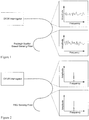
- An example of this unique-broadband spectrum being reflected from two segments along the length of the sensor is depicted in Figure 1 .
- OFDR measurement data and associated baseline data are "delta correlated" when extracting a measure of phase and/or strain.
- the spectrum reflected from a given location is sufficiently different from the reflected spectrum of an adjacent segment, that an accurate measure of delay along the length of the fiber must be known in order to make a meaningful comparison/correlation of OFDR measurement data and associated baseline data, which is needed to in turn obtain a meaningful measure of strain along the length of the sensor.
- This can be a weakness of a Rayleigh scatter measurement approach if the processing to extract meaningful strain responses in a practical sensing environment is extensive.
- the broadband response of Rayleigh scatter does allow a direct measure of delay as described for example in “Optical Position and/or Shape Sensing,” US 20110109898 . Further, the broadband response enables advanced techniques such as the use of an extended reference as described for example in “Registration of an Extended Reference for Parameter Measurement in an Optical Sensing System,” US 2011038512 . While Rayleigh scatter is a weak signal, the broadband nature also allows several strategies to improve robustness of a given strain measurement if the processing can be afforded in a given application.
- FBGs written with a high density along the length of the optical sensor is another approach in optical fiber based strain sensing.
- Each FBG location along the length of the fiber reflects a discrete frequency based on the periodicity of the written grating.
- Figure 2 depicts an example of how each location along the fiber reflects the same discrete frequency based on the period of the written grating.
- the signal strength of a FBG sensor is on the order of three times greater than that of a Rayleigh scatter based sensor. This increased signal reduces overall noise of a given strain measurement and facilitates deployment of a sensor by enabling more optical connections to be used when connecting a sensor to an OFDR instrument.
- the spectrum reflected from any given segment of fiber along the length of a sensor is similar with an FBG based sensor.
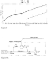
- a continuous FBG based fiber may have distortions at the stitch interfaces reducing manufacturing yields. As the measurement and reference become misaligned in delay, these interfaces can cause distortions in a reconstruction of strain. An example of such a manufacture defect is depicted in Figure 3 .
- a Rayleigh scatter based sensor has the advantages of a direct measurement of delay along the length of the sensor, broadband strategies such as use of an extended reference are available, and the sensors are easy to manufacture.
- Rayleigh scatter based sensors are delta correlated due to their broadband nature and are susceptible to environmental distortions. Further, Rayleigh scatter is a weak effect causing the sensors to suffer from a low signal to noise level.
- FBG based fibers are not delta correlated and provide an easy measure of strain in aggressive sensing environments such as a fiber that experiences motion during a measurement. Further, FBG sensors are on the order of 3-4 times stronger than a typical Rayleigh scatter fiber.
- FBG sensors do not allow a measure of delay causing a given level of uncertainty in a strain measurement. The narrow band response does not allow a direct measurement of delay and prevents broadband strategies from being utilized.
- An example aspect of the technology described in this application includes an optical sensor that includes an optical fiber inscribed with a repeated refraction pattern including overlapping chirped frequency fiber Bragg gratings such that light scattered from a location on the optical fiber is scattered at multiple frequencies in a range of frequencies. At least two of the inscribed patterns overlap at every measurement point along the entire length of the sensor.
- the optical sensor may also include multiple optical light guiding cores within the optical fiber, where each of the multiple optical light guiding cores is inscribed with the repeated refraction patterns.
- Another aspect includes an optical sensing system that includes the optical sensor along with control circuitry that detects measurement scatter data from the optical fiber over the range of frequencies and determines a change in the detected measurement scatter data over the range of frequencies. A parameter describing a state of the optical fiber is determined based on the determined change in the detected measurement scatter data.
- Examples of the parameter includes a measure of strain along a length of the optical sensor, a measure of change in optical phase along a length of the optical sensor, or a measure of delay along a length of the optical sensor.
- control circuitry obtains baseline scatter data for the optical sensor and determines the delay based on a comparison that uses the baseline scatter data and the detected measurement scatter data.
- the delay may be used for example to compensate for a misalignment between the baseline scatter data and the detected measurement scatter data.
- the optical sensing system detected measurement scatter data with a scattering amplitude greater than 10dB.
- the control circuitry obtains baseline scatter data for the optical sensor and Fourier transforms the baseline scatter data from a temporal domain into a spectral domain. A first half spectral response of the baseline scatter data and a second half spectral response of the baseline scatter data are generated. Similarly, the detected measurement scatter data are Fourier transform from the temporal domain into the spectral domain, and a first half spectral response of the detected measurement scatter data and a second half spectral response of the detected measurement scatter data are generated. The first half spectral response of the baseline scatter data and the first half spectral response of the detected measurement scatter data are processed to determine a first result.
- the second half spectral response of the baseline scatter data and the second half spectral response of the detected measurement scatter data are processed to determine a second result.
- a measure of the delay is determined based on the first and second results.
- a phase difference may also be determined from the processed spectral responses.
- another example feature is to determine a measure of a phase slope associated with a chirp rate of a grating and compare the measure phase slope to a phase slope generated from a baseline scatter measurement of the optical fiber.
- a measure of strain and/or delay at a location on the optical fiber may be determined based on the phase slope comparison.
- the measured phase slope may be compared to a phase slope generated from a baseline scatter measurement of the optical fiber to determine a phase offset.
- a measure of delay at a location on the optical fiber may then be determined based on the phase offset.
- the detected measurement scatter data is used to determine a measure of delay along the length of the sensing fiber, and the measured delay is used to determine a measure of strain along the length of the optical fiber.
- a measure of delay along a length of the optical sensor may be determined by analyzing amplitude fluctuations in the gratings inscribed along the length of the sensor due to interference of the written gratings.
- one or more of the chirped frequency fiber Bragg grating scattering responses may be filtered out from the overlapped chirped frequency fiber Bragg grating responses at a location along the optical sensor.
- control circuitry includes OFDR circuitry permits a reflection wavelength of the overlapping chirped frequency fiber Bragg gratings to exceed a wavelength range of the OFDR circuitry but still allows spectral shifts greater than a scan range of the OFDR circuitry to be measured by the OFDR circuitry.
- Another example aspect of the technology includes a method for making an optical sensor that includes an optical fiber.
- the method includes inscribing a first chirped-frequency, light refracting pattern on the optical fiber at every measurement point along at least a portion of the length of the sensor, and inscribing a second chirped-frequency, light refracting pattern on the optical fiber that overlaps the first inscribed light refracting pattern at every measurement point along at least the portion of the length of the sensor.
- the optical fiber inscribed with the overlapping first and second light refracting patterns scatters light from a location on the optical fiber at multiple frequencies in a range of frequencies.
- the first and second light refracting patterns can be overlapping chirped frequency fiber Bragg gratings and/or can overlap at every point along the entire length of the sensor.
- the first and second light refracting patterns create an overlapped modulated index of refraction pattern.
- Hardware implementations of certain aspects of the technology may include or encompass, without limitation, digital signal processor (DSP) hardware, a reduced instruction set processor, hardware (e.g., digital or analog) circuitry including but not limited to application specific integrated circuit(s) (ASIC) and/or field programmable gate array(s) (FPGA(s)), and (where appropriate) state machines capable of performing such functions.
- DSP digital signal processor
- ASIC application specific integrated circuit
- FPGA field programmable gate array
- a computer is generally understood to comprise one or more processors or one or more controllers, and the terms computer, processor, and controller may be employed interchangeably.
- the functions may be provided by a single dedicated computer or processor or controller, by a single shared computer or processor or controller, or by a plurality of individual computers or processors or controllers, some of which may be shared or distributed.
- processor or “controller” also refers to other hardware capable of performing such functions and/or executing software, such as the example hardware recited above.
- circuitry and “circuit” are used herein to refer to structures in which one or more electronic components have sufficient electrical connections to operate together or in a related manner.
- an item of circuitry can include more than one circuit.
- An item of circuitry that includes a processor may sometimes include hardware and software components.
- Software refers to stored or transmitted data that controls operation of the processor or that is accessed by the processor while operating, and hardware refers to components that store, transmit, and operate on the data. The distinction between software and hardware is not always clear-cut, however, because some components share characteristics of both.
- a given processor-implemented software component can often be replaced by an equivalent hardware component without significantly changing operation of circuitry, and a given hardware component can similarly be replaced by equivalent processor operations controlled by software.
- Circuitry can be described structurally based on its configuration or other characteristics. For example, circuitry that is configured to perform control operations is sometimes referred to as control circuitry and circuitry that is configured to perform processing operations is sometimes referred to as processing circuitry.
- interfaces, processors, servers, memories, detectors, user interfaces, and other items may be included in a system in which they are operated automatically or partially automatically.
- system and the term apparatus both refer to a combination of two or more parts or components that can perform an operation together.
- a system and an apparatus may be characterized by configured operation.
- data may be (i) delivered from RAM to a processor; (ii) carried over any type of transmission medium (e.g., wire, wireless, optical, etc.); (iii) formatted and/or transmitted according to numerous formats, standards or protocols, such as Ethernet (or IEEE 802.3), SAP, ATP, Bluetooth, and TCP/IP, TDMA, CDMA, 3G, etc.; and/or (iv) encrypted to ensure privacy or prevent fraud in any of a variety of ways.
- transmission medium e.g., wire, wireless, optical, etc.
- CFBG fiber Bragg grating
- An overlapped fiber Bragg grating means that several gratings have been written along the length of the fiber such that their respective index of refraction modulations are partially superimposed along the length of the sensor.
- using an overlapped CFBG fiber sensor substantially simplifies the data processing needed to extract a measure of deformation along the length of an optical sensor, which is a significant advantage for example in optical fiber-based strain sensing.
- An OFDR measurement is acquired by measuring an interference pattern produced by mixing scattered light with a reference path and generating an interference pattern at a photodetector as a tunable light source (TLS) is swept through a range of optical frequencies as depicted in Figure 4A .
- TLS tunable light source
- Light from a tunable laser source is launched into a pair of independent optical fiber interferometers, separated by a fiber optic coupler.
- the incoming light is further split into two paths.
- the light passes through a polarization controller (PC) and a circulator before entering the sensing fiber.
- PC polarization controller
- a polarization beamsplitter (PBS) splits the light into two orthogonal polarization states S and P, and the split interference pattern is detected independently at photodetectors labeled S and P.
- This interference pattern includes data in the spectral domain and represents the frequency response of a length of sensing fiber.
- a subsequent Fourier transform of the interference pattern data produces corresponding data in the temporal domain which contains information detailing the scattering response of the fiber.
- An OFDR measurement is commonly displayed as scattering amplitude verse delay along the length of the fiber.
- delay relates to the principle that light travels a given distance based on the speed of light and the index of refraction of a material.
- Even though scattering amplitude is commonly depicted, the signal is complex-valued with both an amplitude and a phase response.
- a useful property of an OFDR measurement is related to a property of a Fourier transform.
- Each measurement "point" in the temporal domain represents the entire frequency response of that location as a tunable laser is swept through a range of frequencies.
- FIG 4B shows an example OFDR system connected to a fiber optic sensor.
- the OFDR system includes a tunable light source, an optical network that includes a measurement interferometer and a laser monitor interferometer, a Rayleigh scatter data acquisition (DAQ) system, a system controller data processor including one or more microprocessors for performing processing of Rayleigh scatter data stored in memory along with various processing programs including one or more correlation algorithms.
- DAQ Rayleigh scatter data acquisition
- the system controller initiates the sweep of the tunable laser source over an optical frequency range.
- the light is split between the laser monitor optics and measurement optics.
- the laser monitor optics typically includes an absolute wavelength reference (though not shown in Figure 4B ) and a relative phase monitor.
- the light input to the measurement interferometer is split between a reference path and the fiber optic sensor. Reflected light from the sensor comes back through the same path used to inject light into the sensor.
- the light input to the measurement interferometer is split between a reference path and the sensor, and the light comes back into the measurement interferometer through an output port of the device.
- receive (Rx) and transmit (Tx) type OFDR measurements the light from the reference path and the light that traverses the sensor is interfered, and the interferogram is split by a polarization beam splitter (PBS) and then detected by photo-sensitive s and p detectors.
- PBS polarization beam splitter
- the interferograms are converted by the DAQ into electronic signals representing detected Rayleigh scatter from the sensor, and the signals from the laser monitor are detected and used by the system controller to resample the measured Rayleigh scatter signals to equal optical frequency increments.
- Signals from an absolute wavelength reference (not shown in Figure 4B ) are used to spectrally register the acquired data as a function of absolute optical frequency.
- the system controller Fourier Transforms the resampled data into the temporal domain for filtering and time domain response analysis such as, for example, determination of return loss, group delay, birefringence, beat length, polarization extinction ratio, and optical phase versus delay down the device, and/or construction of the device Jones Matrix.
- the measurement data may then be Fourier Transformed back to the optical frequency domain for optical frequency domain analysis to determine, for example: insertion loss, phase, group delay, chromatic dispersion, polarization dependent loss, differential group delay, versus optical frequency or wavelength.
- example embodiments perform a phase-based calculation of deformation along the length of the core. This enables higher accuracy strain measurements as compared to other strain sensing techniques due to the ability to detect sub-index changes in length. See “Optical Position and/or Shape Sensing," US 20110109898 .
- Optical Position and/or Shape Sensing US 20110109898 .
- a given OFDR measurement When a given OFDR measurement is acquired, it possesses both a phase and amplitude response along the length of the sensing fiber.
- an optical phase difference can be extracted along the length of the fiber. As light traverses a distance, it accumulates optical phase. Thus, by gaining a measure of the phase difference along the length of the fiber, one can gain a measure of the how much the length of the fiber has changed.
- a baseline scattering profile is obtained in the temporal domain with an OFDR instrument.
- the frequency response in the spectral domain at a location along the sensor is determined using fiber scattering.
- a subsequent OFDR measurement can be performed to measure the response of a deformed sensor.
- a measure of change in phase along the length of the sensor is determined. This change in phase is proportional to change in length of the sensor, and a derivative of this change in length is a direct measure of strain along the length of the sensor.
- a delay mismatch can exist between a measurement OFDR scan and a baseline OFDR scan if a strain causes a change in length that misaligns the measurement and baseline data in physical length. Thus, to accurately measure phase and/or strain, tracking delay along the length of the sensor is needed.
- the inventors realized that if an optical fiber sensor is constructed having a broadband response that is not "delta-correlated" a more robust sensor can be produced with simplified data processing requirements to determine one or more parameters like strain.
- the term “delta-correlated” refers to when a measurement OFDR scan and a baseline OFDR scan of a fiber must be aligned to a high accuracy in physical distance along the length of the fiber in order to accurately compare them and produce a valid parameter (e.g., strain) measurement, e.g., during parameter processing.
- the inventors produced such an optical fiber sensor with an overlapped pattern of index of refraction modulations written into a fiber such that multiple discrete frequencies are scattered at each location along the length of the fiber. Hence, each location along the chirped fiber Bragg grating (CFBG) fiber reflects a designed, broadband response.
- CFBG fiber Bragg grating
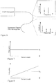
- FIG. 6 A non-limiting example of a CFBG fiber sensor is depicted in Figure 6 .
- An overlapped chirped fiber Bragg grating fiber sensor reflects several discrete frequencies at a single location along the length of the fiber. Due to the chirped nature of the written Bragg gratings, a location further along the sensor will reflect a different set of discrete frequencies dependent on the slope (frequency/distance) of the grating and the distance advanced.
- the CFBG fiber offers increased signal strength, avoids defects as a result of contiguous gratings, provides a broadband response for the direct measure of delay, enables broadband strategies such as an extended reference, and allows strain to be measured in a fashion that is not delta correlated (aligned) with a baseline OFDR measurement causing strain measurements to be more robust in the presence of sensor motion.
- CFBG fiber was constructed and tested. Testing showed the CFBG fiber to be more robust than conventional fiber types used in optical fiber based strain sensing while still providing accurate strain measurements.
- a CFBG fiber has several chirped FBGs "written" on the fiber such that they overlap along the length of the sensing fiber.
- the chirped FBGs are densely overlapped.
- an FBG is a type of reflector constructed in a short segment of optical fiber that reflects particular wavelengths of light and transmits all others. This is achieved by creating a periodic variation in the refractive index of the fiber core, which generates a wavelength specific dielectric mirror.
- a fiber Bragg grating can therefore be used as an inline optical filter to block certain wavelengths or as a wavelength-specific reflector.
- Fiber Bragg gratings are created by inscribing or writing a systematic (periodic or aperiodic) variation of refractive index into the core of optical fiber using an intense ultraviolet (UV) source such as a UV laser.
- UV intense ultraviolet
- a typical FBG is "written" into the fiber such that a single optical frequency is reflected along the entire length of the fiber based on the period of the written grating.
- a grating into a fiber such as using interference and masking processes.
- photomasking for example, a photomask is placed between the UV light source and the photosensitive fiber. The shadow of the photomask then determines the grating structure based on the transmitted intensity of light striking the fiber.
- Complex grating profiles can be manufactured by exposing a large number of small, partially overlapping gratings in sequence. Advanced properties such as phase shifts and varying modulation depth can be introduced by adjusting the corresponding properties of the subgratings.
- Figure 7 depicts an example of an FBG fiber reflecting a single frequency, v c , along the length of a sensor.
- a chirped FBG differs from a single frequency fiber in that the reflected frequency is dependent on the location along the length of the sensor.
- the positive slope line in Figure 8 is an example of how the reflected frequency of a chirped FBG sensor is dependent on the location along the length of the sensor.
- a given location along the length of the fiber see example point A, reflects multiple different and discrete frequencies as shown in Figure 9 .
- Figure 9 shows an overlapped chirped FBG fiber reflecting multiple discrete frequencies at a single location along the length of the sensor.
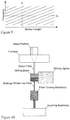
- Figure 10 is a diagram illustrating a schematic of an example optical fiber draw tower used to manufacture optical fiber with optics for writing gratings into the fiber.
- the manufacture of a Bragg grating type optical fiber may be performed similar to that of industrial standard optical fiber, such as Corning SMF-28.
- Figure 10 shows an optical fiber drawer tower. A glass preform of both cladding and optical core material is heated in a furnace that brings the glass into a molten state. It is drawn to the correct diameter as it exits the furnace. The drawn optical fiber is coated with a protective coating, such as Polyimide. Once coated, the optical fiber is spooled and the process completes.
- a protective coating such as Polyimide
- grating writing optics When gratings are written into the optical fiber, writing optics are placed within this process. Based on the type of protective coating, the grating writing optics can be placed before or after the fiber coating machinery. A writing beam is timed such that a grating is written when the drawn fiber advances the width of the writing beam. Gratings can be written with a UV source and are controlled through the use of a phase mask which controls the properties of the written grating.
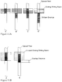
- Figure 11A shows an example of producing a continuous grating fiber with a limited writing beam width during the drawing process.
- the writing optics produce a beam of short duration that writes the gratings into the optical fiber (A).
- the draw tower advances the drawn optical fiber a distance equal to the width of the writing beam (B).
- the writing optics once again write a grating into the optical fiber producing a grating continuous with the previous written section (C).
- the process completes along the length of the drawn fiber (D).
- FIG. 11B shows an example process for producing an overlapped, chirped grating fiber.
- a chirped grating fiber is produced by creating a grating phase mask that produces a grating that reflects a different frequency along the length of the writing beam (A).
- the writing beam is activated before the draw tower has advanced the optical fiber a distance greater than the width of the writing beam (B). Since the grating is designed to reflect a different frequency along the width of the writing beam, interference is minimized in the regions of overlap when the fiber is advanced a given overlap distance.
- FIG 12 is a flowchart diagram illustrating an example manufacturing procedure for making an overlapped, chirped grating fiber.
- an optical fiber draw tower draws molten galls to a desired optical fiber diameter (step S1).
- Writing optics expose optical fiber to a UV source through a photomask (step S2).
- the UV exposure creates a modulated index of refraction pattern in the optical fiber producing a chirped grating (step S3).
- the drawn optical fiber is advanced an overlap distance between chirped gratings (step S4).
- the writing optics again expose the optic fiber to a UV source creating an overlapped modulated index of refraction pattern (step S5).
- Steps S4 and S5 may be repeated for a desired length along the fiber. These procedures may also be applied to each optical core of a multi-core fiber.
- a Rayleigh scatter response produces a signal that is compared (e.g., delta correlated) with the baseline reference data.
- a FBG fiber does not have a spatial restriction on the delay that exists between a measurement and baseline scatter response.
- the CFBG fiber is a hybrid of these two scattering mechanisms with multiple discrete frequencies overlapping at each location along the sensor fiber.
- coherence between measurement and baseline data will be recovered periodically along the length of the sensing fiber.
- an estimate of strain applied to a fiber can be obtained by comparing measurement and baseline data points within a measurement scan.
- strain sensing technology is based on measuring changes in slope of the chirped grating along the length of the sensing fiber.
- a spacing of 5nm between gratings produces a coherence every two indices in the temporal domain for a 10 nanometer scan and four indices for a 20 nanometer scan.
- strain is proportional to the following: ⁇ ⁇ ⁇ T n T n ⁇ p *
- strain ⁇ is proportional to the phase change between a complex valued point in the delay domain ( T) at index ( n) and a previous point separated by the distance to the next coherent location ( p) .
- T delay domain
- n index
- p next coherent location
- a substantial phase slope is observed in the strain response depicted in Figure 13 .
- This slope is a result of the pitch of the grating.
- the pitch of the grating is 20 nanometers over 28 millimeters, and the spacing between two coherent locations is 160 micrometers for a measurement taken over a 10 nanometer spectral range.
- change in center frequency as a result of the chirp of the grating between the two coherent indices is approximately 114 picometers.
- This spectral shift corresponds to a phase slope of approximately 1150 radians.
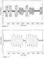
- the strain response is observed as depicted in Figure 14 , which oscillates in the region of a bend for a twisted multicore sensing fiber.
- An outer core of the fiber will experience alternating periods of elongation or compression as the fiber is bent at a rate equal to the twist of the outer cores.
- a close up of the first 4000 index of the strain response in Figure 14 is depicted in Figure 15 .
- This type of strain computation offers several advantages.
- the broadband nature of the CFBG fiber enables measurement of delay along the length of the fiber. While several methods exist for the extraction of delay, an example method is to resample a single given measurement into two different spectral representations of the sensor. Each response represents half of the spectral range of the original measurement and each will have a different center frequency. If a similar operation is performed on the baseline reference, a comparison of the phase difference between the two provides a measure of delay.
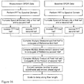
- a non-limiting example algorithm is shown in the flow chart in Figure 16 .
- a measurement of a deployed sensor is obtained with an OFDR interrogation system.
- a baseline reference of the given sensor is obtained.
- Both the measurement and baseline reference data are Fourier transformed from the temporal domain to the spectral domain.
- the spectrums of both the measurement and baseline reference data are then truncated into two half data segments.
- the first half data segment represents the lowest frequency response in the spectrum while the later second half data segment represents the higher frequencies in the spectrum.
- All four half spectral data sets, first and second half measurement and first and second half baseline are inverse Fourier transformed from the spectral domain to the temporal domain.
- the first half measurement data is complex multiplied with the complex conjugate of the first half baseline reference data.
- the second half measurement data is complex multiplied with the complex conjugate of the second half baseline reference data.
- the resulting product of the first half data sets is complex multiplied with the resulting product of the second half data sets.
- the data is converted to polar coordinates to extract a resulting phase signal along the length of the sensing fiber. This phase signal is proportional to delay along the length of the sensor.
- the delay result may be used in a variety of applications, one example is to use the delay to compensate for misalignment between measurement and baseline OFDR data sets, e.g., shift one of the data sets so that an accurate comparison can be made. In this way, an accurate phase measurement can be made.
- the algorithm in Figure 16 was performed on an example test CFBG sensor which resulted in the strain depicted in Figure 17 . Areas of non-zero strain can cause an elongation or compression of the fiber. A delay mismatch will arise between a measurement and a baseline. Using the example algorithm shown in the flow chart of Figure 16 , the delay response can be calculated as depicted in Figure 18 , which shows that a slow accumulation of delay occurs up to index 2000. A region of higher strain between index 2000 and 7000 accumulates a greater delay. After index 7500, no strain is observed and the delay remains constant.
- An alternative example delay calculation can be performed based on a recognition that the overlapping gratings create an interference pattern in the amplitude of the reflection. This amplitude is a function of the relative phase between the gratings at that point in the fiber, and therefore, does not change after the gratings are written.
- the spacing between the gratings e.g., 5nm determines the center frequency of this pattern, and allows us to separate it from the background noise in the amplitude, and allows use of a simple phase comparison between the reference and the measurement to determine the delay difference between the two signals. In cases where there are three gratings present, and in cases where the reference and measurement have different grating present in the sweep range, this method may fail. Both of these cases, (the three gratings and the different gratings between measurement and reference) occur in the same place under low strain conditions.
- the chirped nature of the FBG may be used to extract a measure of alignment, or delay, along the length of the sensor. Recall the resulting phase slope that was produced from the strain computation depicted in Figure 13 . Neighboring coherent points in the temporal domain produce a phase slope due to each point representing a different frequency in of the chirped FBG. The baseline measurement has the same slope. If the strain of the measurement is misaligned in delay with respect to the baseline strain response, a phase offset is produced proportional to the misalignment.
- An algorithm may be used that systematically shifts the baseline strain response with respect to the measurement strain response at a location along the fiber and finds the minimum phase offset value. Since the phase offset value is proportional to delay, the signals are aligned when the offset is minimized. Alternatively the resulting phase value could be directly scaled to a measure of delay.
- the result of a shifting a reference with respect to the measurement is depicted in the example in Figure 19 which shows that the phase offset is proportional to the shift between the measurement and baseline.
- a minimum peak is formed by taking the absolute value of the phase difference to facilitate detection of the minimum.
- the darker lined profile is compared to a similar measurement shifted by 8 indices in the temporal domain.
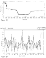
- An extended reference is a technique in which a baseline measurement of a fiber is recorded over a frequency range that is greater than the frequency range of a given OFDR measurement. As the fiber is strained, its reflected spectrum will shift in frequency. In the case of a conventional FBG fiber, if the frequency shift is beyond the frequency span of a given measurement, no signal will be observed as shown in the example of Figure 20 .
- the extended reference technique can be implemented with scattering profiles that are broadband as is the case for the described Rayleigh scatter in "Registration of an Extended Reference for Parameter Measurement in an Optical Sensing System," US 2011038512 .
- this technique may be further used with a CFBG fiber in example embodiments.
- the signal is not necessarily broadband, but due to the chirp, discrete frequencies are shifted into the measurement range as long as the chirp is written over a frequency range that exceeds the measurement spectral range. This is illustrated in an example of Figure 21 .
- a chirped grating could be written over a range of, for example, 30 nanometers while a 10 nanometer measurement is performed to allow for shifts of the center frequency as high as 10 nanometers without loss of signal.
- the technology increases the accuracy of parameter measurements.
- the CFBG optical fiber transmits light along a light guiding core similar to a conventional optical fiber.
- light can be transmitted along a fast or slow axis based on the polarization of the light.
- OFDR uses a beamsplitter and two photodetectors to ensure detection of light that travels on both transmissions axis in the optical core. This is illustrated in the diagram of an OFDR network in Figure 4 . If a delay exists between light that is transmitted along these two axis, a beating can occur between the signals that is detrimental the accuracy of a parameter measurement of the fiber.
- the term beating is used to refer to the interaction between two signals in a way that produces a periodic response.
- a phase difference between the S photodetector OFDR measurement and the P photodetector OFDR measurement is depicted in Figure 22 .
- a beating is observed along the length of the signal.
- a phase difference that accumulates between the states represents birefringence in the sensor.
- a Fourier transform of this signal produces a measure of the frequency of this beating as depicted in an example shown in Figure 23 .
- the length of the displayed 15000 fiber index is 1.2 meter.
- An FFT of this signal produces a peak at 172, which corresponds to a spatial frequency of 7 millimeters. This is the spacing between overlapping gratings of the CFBG fiber.
- a residual oscillation is observed with a different amplitude based on location along the sensor. This indicates that a non constant delay shift would be required to completely remove the oscillation from the length of the sensor. Accounting for the beating between the two states will improve accuracy of the measurement of a desired parameter when utilizing a CFBG fiber.
- the overlapped chirped grating fiber is designed such that each location in the fiber reflects several discrete frequencies.
- the response of the OCG fiber may be filtered to isolate the response of only one of these signals and cause the fiber to behave similarly to a conventional FBG sensor. For example, if four frequencies were reflected at each location in the fiber, the response may be filtered to have four separate representations of the fiber, each similar to a conventional FBG sensor, by applying a quadratic phase response in the temporal domain to remove the slope on the frequency in the spectral domain. A band pass filter can then be placed at each reflected frequency to isolate that specific response. This allows highly robust strain measurements to be made in the presence of motion as there would be less of a restriction on the spatial coherence since overlapped frequencies would no longer interfere.
- the fiber contains chirped gratings
- the beaks are broader than expected which implies that the chirped grating is not perfectly linear.
- To further refine the response one can window around a peak to refine the quadratic response that was applied in the temporal domain.
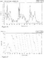
- the found phase difference from parabolic is plotted in Figure 27 .
- the CFBG scattering mechanism produces a broadband frequency response that allows direct computation of a delay mismatch along the length of the fiber and utilization of extended reference techniques.
- the scattering mechanism is periodically coherent along the length of the sensor, allowing one to directly calculate a measure of strain from a single scan. Due to the short distances between points, this strain computation is highly robust to distortions that occur due to motion of the sensor during a measurement. Since gratings are directly written into the fiber, high signal to noise can be manufactured increasing accuracy of strain measurements and allowing for more optical connections in a deployed OFDR network. Due to the chirped nature of the written FBGS, the gratings can be densely overlapped without phase distortions making the fiber easy to manufacture without defects.
- a CFBG fiber posses many desirable traits without the drawbacks that conventional scattering mechanisms suffer when used for fiber optic based strain sensing.
Landscapes
- Physics & Mathematics (AREA)
- General Physics & Mathematics (AREA)
- Optics & Photonics (AREA)
- Engineering & Computer Science (AREA)
- Manufacturing & Machinery (AREA)
- Chemical & Material Sciences (AREA)
- Analytical Chemistry (AREA)
- Length Measuring Devices By Optical Means (AREA)
Claims (13)
- Capteur optique comprenant :une fibre optique sur laquelle est inscrit un motif de réfraction répété comportant des réseaux de Bragg sur fibre à fréquences à compression d'impulsions chevauchants à plusieurs emplacements le long de la fibre optique de sorte que la lumière réfléchie à partir d'un emplacement sur la fibre optique est réfléchie à plusieurs fréquences dans une plage de fréquences,dans lequel au moins deux des motifs de réfraction répétés inscrits se chevauchent à chaque point de mesure sur toute la longueur du capteur.
- Capteur optique selon la revendication 1, comprenant en outre plusieurs coeurs optiques de guidage de lumière dans la fibre optique, chacun des plusieurs coeurs optiques de guidage de lumière ayant les motifs de réfraction répétés inscrits sur celui-ci.
- Système de détection optique comprenant :le capteur optique selon la revendication 1,un circuit de commande, couplé à la fibre optique, configuré :pour détecter des données de réflexion de mesure à partir de la fibre optique sur la plage de fréquences,pour déterminer un changement des données de réflexion de mesure détectées sur la plage de fréquences, etpour déterminer un paramètre décrivant un état de la fibre optique sur la base du changement déterminé des données de réflexion de mesure détectées.
- Système de détection optique selon la revendication 3, dans lequel le paramètre est une mesure de contrainte, de phase optique ou de retard sur une longueur du capteur optique.
- Système de détection optique selon la revendication 4, dans lequel le circuit de commande est configuré :pour obtenir des données de réflexion de ligne de base pour le capteur optique ;pour effectuer une transformée de Fourier sur les données de réflexion de ligne de base d'un domaine temporel à un domaine spectral ;pour générer une réponse de la première moitié de plage spectrale des données de réflexion de ligne de base et une réponse de la deuxième moitié de plage spectrale des données de réflexion de ligne de base ;pour effectuer une transformée de Fourier sur les données de réflexion de mesure détectées du domaine temporel au domaine spectral ;pour générer une réponse de la première moitié de plage spectrale des données de réflexion de mesure détectées et une réponse de la deuxième moitié de plage spectrale des données de réflexion de mesure détectées ;pour traiter la réponse de la première moitié de plage spectrale des données de réflexion de ligne de base et la réponse de la première moitié de plage spectrale des données de réflexion de mesure détectées afin de déterminer un premier résultat ;pour traiter la réponse de la deuxième moitié de plage spectrale des données de réflexion de ligne de base et la réponse de la deuxième moitié de plage spectrale des données de réflexion de mesure détectées afin de déterminer un deuxième résultat ; etpour déterminer une mesure du retard sur la base des premier et deuxième résultats.
- Système de détection optique selon l'une des revendications 3 à 5, dans lequel le circuit de commande est configuré :pour obtenir des données de réflexion de ligne de base pour le capteur optique, etpour déterminer un retard sur la base d'une comparaison qui utilise les données de réflexion de ligne de base et les données de réflexion de mesure détectées.
- Système de détection optique selon la revendication 6, dans lequel le circuit de commande est configuré pour utiliser le retard afin de compenser un désalignement entre les données de réflexion de ligne de base et les données de réflexion de mesure détectées.
- Système de détection optique selon la revendication 3, dans lequel le circuit de commande est configuré pour déterminer une mesure d'une pente de phase associée à un taux de compression d'impulsions d'un réseau, comparer la pente de phase mesurée à une pente de phase générée à partir d'une mesure de réflexion de ligne de base de la fibre optique, et déterminer une mesure de contrainte ou de retard à un emplacement sur la fibre optique sur la base de la comparaison de pente de phase.
- Système de détection optique selon la revendication 3, dans lequel le circuit de commande est configuré pour extraire une mesure de retard sur une longueur du capteur optique en analysant les fluctuations d'amplitude dans les réseaux inscrits sur la longueur du capteur en raison de l'interférence des réseaux.
- Système de détection optique selon la revendication 3, dans lequel le circuit de commande est configuré pour filtrer une ou plusieurs réflexion(s) à partir des réseaux de Bragg sur fibre à fréquences à compression d'impulsions en chevauchement à un emplacement le long du capteur optique.
- Système de détection optique selon la revendication 3, dans lequel :le circuit de commande comporte un circuit OFDR,une longueur d'onde de réflexion des réseaux de Bragg sur fibre à fréquences à compression d'impulsions chevauchants dépasse une plage de longueurs d'onde du circuit OFDR, etle circuit OFDR est configuré pour mesurer la lumière réfléchie à partir d'un emplacement sur la fibre optique ayant une dérive spectrale supérieure à une plage de balayage du circuit OFDR.
- Procédé de réalisation d'un capteur optique qui comporte une fibre optique, le procédé comprenant le fait :d'inscrire un premier motif de réfraction de lumière à fréquences à compression d'impulsions sur la fibre optique à chaque point de mesure le long d'au moins une partie d'une longueur du capteur ; etd'inscrire un deuxième motif de réfraction de lumière à fréquences à compression d'impulsions sur la fibre optique qui chevauche le premier motif de réfraction de lumière inscrit à chaque point de mesure sur au moins une partie de la longueur du capteur, le deuxième motif de réfraction de lumière à fréquences à compression d'impulsions ayant un même motif que le premier motif de réfraction de lumière à fréquences à compression d'impulsions,dans lequel la fibre optique sur laquelle sont inscrits les premier et deuxièmes motifs de réfraction de lumière à fréquences à compression d'impulsions chevauchants réfléchit la lumière à partir d'un emplacement sur la fibre optique à plusieurs fréquences dans une plage de fréquences.
- Procédé selon la revendication 12, réalisé en utilisant le capteur optique de la revendication 1 ou 2.
Applications Claiming Priority (2)
| Application Number | Priority Date | Filing Date | Title |
|---|---|---|---|
| US201361834526P | 2013-06-13 | 2013-06-13 | |
| PCT/US2014/041685 WO2014200986A1 (fr) | 2013-06-13 | 2014-06-10 | Fibre de détection à réseau de bragg sur fibre à pas variable et à chevauchement, et procédés et appareil pour une mesure de paramètre à l'aide cette dernière |
Publications (3)
| Publication Number | Publication Date |
|---|---|
| EP3008425A1 EP3008425A1 (fr) | 2016-04-20 |
| EP3008425A4 EP3008425A4 (fr) | 2017-02-01 |
| EP3008425B1 true EP3008425B1 (fr) | 2018-08-08 |
Family
ID=52022702
Family Applications (1)
| Application Number | Title | Priority Date | Filing Date |
|---|---|---|---|
| EP14810406.0A Active EP3008425B1 (fr) | 2013-06-13 | 2014-06-10 | Fibre de détection à réseau de bragg sur fibre à pas variable et à chevauchement, et procédés et appareil pour une mesure de paramètre à l'aide cette dernière |
Country Status (3)
| Country | Link |
|---|---|
| US (2) | US9772176B2 (fr) |
| EP (1) | EP3008425B1 (fr) |
| WO (1) | WO2014200986A1 (fr) |
Families Citing this family (28)
| Publication number | Priority date | Publication date | Assignee | Title |
|---|---|---|---|---|
| EP3008425B1 (fr) * | 2013-06-13 | 2018-08-08 | Intuitive Surgical Operations, Inc. | Fibre de détection à réseau de bragg sur fibre à pas variable et à chevauchement, et procédés et appareil pour une mesure de paramètre à l'aide cette dernière |
| US9606021B2 (en) * | 2013-06-18 | 2017-03-28 | Intuitive Surgical Operations, Inc. | Methods and apparatus segmented calibration of a sensing optical fiber |
| US10234345B2 (en) | 2014-07-04 | 2019-03-19 | Hifi Engineering Inc. | Method and system for detecting dynamic strain |
| CN107430013B (zh) | 2015-04-02 | 2020-08-18 | 直观外科手术操作公司 | 使用参考光纤干涉数据配准测量的光纤干涉数据 |
| US10281341B2 (en) * | 2015-05-21 | 2019-05-07 | Hifi Engineering Inc. | Methods and systems using optical fiber interferometry |
| BR112015025214A2 (pt) * | 2015-05-28 | 2017-08-22 | Ericsson Telecomunicacoes Sa | Dispositivo e método para monitoramento de link de fibra óptica |
| CN105137533B (zh) * | 2015-10-09 | 2017-11-03 | 南京航空航天大学 | 一种啁啾光纤光栅及其制作方法 |
| US10267694B2 (en) * | 2016-01-15 | 2019-04-23 | The United States Of America As Represented By The Administrator Of Nasa | Micrometeoroid and orbital debris impact detection and location using fiber optic strain sensing |
| WO2017190063A2 (fr) * | 2016-04-28 | 2017-11-02 | General Electric Company | Circuits intégrés photoniques et dispositifs de détection photonique |
| KR102408644B1 (ko) | 2016-06-29 | 2022-06-14 | 인튜어티브 서지컬 오퍼레이션즈 인코포레이티드 | Ofdr 인터로게이터 모니터링 및 최적화를 위한 방법 및 장치 |
| CA3027853C (fr) * | 2016-09-30 | 2023-09-12 | Halliburton Energy Services, Inc. | Systemes et procedes pour ameliorer les proprietes de detection acoustique distribuee de fibres optiques |
| GB2554658A (en) * | 2016-09-30 | 2018-04-11 | Fibercore Ltd | Coated fiber manufacture |
| CN110073174B (zh) | 2016-12-29 | 2022-04-26 | 直观外科手术操作公司 | 使用具有多种光传播模式的单芯的感测光纤确定形状参数的方法和装置 |
| US10444072B2 (en) * | 2017-03-21 | 2019-10-15 | Nanyang Technological University | Optical sensor, sensor arrangement and method for sensing |
| EP4253917A3 (fr) * | 2018-06-04 | 2023-12-20 | Intuitive Surgical Operations, Inc. | Réseaux de fibres à chevauchement |
| EP3650806A1 (fr) | 2018-11-08 | 2020-05-13 | Koninklijke Philips N.V. | Capteur à fibre optique, système et procédé d'interrogation du capteur à fibre optique |
| CN113167566B (zh) * | 2018-12-04 | 2023-10-31 | Ofs菲特尔有限责任公司 | 利用偏移芯光纤的高分辨率分布式传感器 |
| EP3822658A1 (fr) * | 2019-11-15 | 2021-05-19 | Aptiv Technologies Limited | Procédé et système de traitement de signal laser pris par un dispositif laser |
| US11237111B2 (en) * | 2020-01-30 | 2022-02-01 | Trustees Of Boston University | High-speed delay scanning and deep learning techniques for spectroscopic SRS imaging |
| US11761828B2 (en) * | 2020-04-14 | 2023-09-19 | Ultra Communications, Inc. | Single wavelength fiber grating sensing with spatial location |
| WO2021209604A1 (fr) | 2020-04-17 | 2021-10-21 | Inphotech Spolka Z Ograniczona Odpowiedzialnoscia | Système de mesure fondé sur une fibre optique, procédé de mesure de paramètres et produit-programme informatique |
| CN111882792B (zh) * | 2020-07-21 | 2022-03-11 | 武汉理工大学 | 基于光栅阵列不饱和干涉的调节方法及分布式周界系统 |
| WO2022165959A1 (fr) * | 2021-02-03 | 2022-08-11 | 深圳大学 | Réseau de fibres comprimées, son procédé de préparation et filtre à réseau de fibres comprimées |
| CN113049410B (zh) * | 2021-02-04 | 2022-04-22 | 南京航空航天大学 | 基于应变非线性加权的复合材料层板光纤冲击位置辨识法 |
| CN114543851B (zh) * | 2022-02-28 | 2024-06-21 | 宁夏回族自治区水利工程建设中心 | 提高信噪比与细节特征的相敏光时域反射仪信号调理方法 |
| US12196551B2 (en) * | 2022-04-08 | 2025-01-14 | Automated Precision Inc. | Broadband interferometry and method for measurement range extension by using same |
| CN115127778B (zh) * | 2022-05-25 | 2023-04-18 | 深圳大学 | 一种简化ofdr系统的方法和装置以及ofdr简化系统、控制装置 |
| CN115901193B (zh) * | 2023-01-09 | 2023-05-05 | 中国人民解放军国防科技大学 | 刻写一体化谐振腔时光纤光栅参数测量方法和系统 |
Family Cites Families (16)
| Publication number | Priority date | Publication date | Assignee | Title |
|---|---|---|---|---|
| NO315249B1 (no) * | 2001-05-25 | 2003-08-04 | Optoplan As | Optisk distribuert bolgeledersensor |
| US6621960B2 (en) * | 2002-01-24 | 2003-09-16 | Oplink Communications, Inc. | Method of fabricating multiple superimposed fiber Bragg gratings |
| US20040101240A1 (en) * | 2002-11-21 | 2004-05-27 | 3M Innovative Properties Company | Method to reduce birefringence and polarization mode dispersion in fiber gratings |
| US7376306B2 (en) * | 2004-08-26 | 2008-05-20 | Avanex Corporation | Slanted Bragg grating gain flattening filter having spatially overlapping elementary filters and a manufacturing method therefor |
| WO2006099056A2 (fr) * | 2005-03-10 | 2006-09-21 | Luna Innovations Inc. | Calcul de la birefringence dans un guide d'onde en fonction de la diffusion de rayleigh |
| US8180185B2 (en) | 2007-03-22 | 2012-05-15 | General Electric Company | Fiber optic sensor for detecting multiple parameters in a harsh environment |
| US8270786B2 (en) | 2008-11-21 | 2012-09-18 | Ofs Fitel, Llc | Optical fiber mode couplers |
| US8433160B2 (en) | 2009-01-30 | 2013-04-30 | Cleveland Electric Laboratories | Smart fastener and smart insert for a fastener using fiber Bragg gratings to measure strain and temperature |
| US8670597B2 (en) | 2009-08-07 | 2014-03-11 | Google Inc. | Facial recognition with social network aiding |
| US8773650B2 (en) | 2009-09-18 | 2014-07-08 | Intuitive Surgical Operations, Inc. | Optical position and/or shape sensing |
| US9335468B2 (en) * | 2010-02-11 | 2016-05-10 | The Hong Kong Polytechnic University | Fiber bragg grating in micro/nanofiber and method of producing the same |
| US9025158B2 (en) | 2010-06-01 | 2015-05-05 | Intuitive Surgical Operations, Inc. | Interferometric measurement with crosstalk suppression |
| IN2014DN03226A (fr) * | 2011-09-30 | 2015-05-22 | Vestas Wind Sys As | |
| JP6214575B2 (ja) * | 2012-03-16 | 2017-10-18 | コーニンクレッカ フィリップス エヌ ヴェKoninklijke Philips N.V. | 関連する物体の位置及び/又は形状測定用の光学的感知システム、方法、及び光学ユニット |
| EP3008425B1 (fr) * | 2013-06-13 | 2018-08-08 | Intuitive Surgical Operations, Inc. | Fibre de détection à réseau de bragg sur fibre à pas variable et à chevauchement, et procédés et appareil pour une mesure de paramètre à l'aide cette dernière |
| US9726573B2 (en) * | 2015-08-19 | 2017-08-08 | Anritsu Corporation | Optical frequency domain reflectometry, optical frequency domain reflectometer, and device for measuring position or shape using the same |
-
2014
- 2014-06-10 EP EP14810406.0A patent/EP3008425B1/fr active Active
- 2014-06-10 US US14/897,973 patent/US9772176B2/en active Active
- 2014-06-10 WO PCT/US2014/041685 patent/WO2014200986A1/fr not_active Ceased
-
2017
- 2017-08-11 US US15/674,564 patent/US20170363410A1/en not_active Abandoned
Non-Patent Citations (1)
| Title |
|---|
| None * |
Also Published As
| Publication number | Publication date |
|---|---|
| EP3008425A4 (fr) | 2017-02-01 |
| US9772176B2 (en) | 2017-09-26 |
| EP3008425A1 (fr) | 2016-04-20 |
| US20160123715A1 (en) | 2016-05-05 |
| WO2014200986A1 (fr) | 2014-12-18 |
| US20170363410A1 (en) | 2017-12-21 |
Similar Documents
| Publication | Publication Date | Title |
|---|---|---|
| EP3008425B1 (fr) | Fibre de détection à réseau de bragg sur fibre à pas variable et à chevauchement, et procédés et appareil pour une mesure de paramètre à l'aide cette dernière | |
| US10295380B2 (en) | Method and apparatus for multiple localized interferometric measurements | |
| US9025158B2 (en) | Interferometric measurement with crosstalk suppression | |
| RU2541139C2 (ru) | Оптическое считывание положения и/или формы | |
| Hotate et al. | Proposal and experimental verification of Bragg wavelength distribution measurement within a long-length FBG by synthesis of optical coherence function | |
| Chan et al. | Enhancement of measurement accuracy in fiber Bragg grating sensors by using digital signal processing | |
| JP2018515799A5 (fr) | ||
| CN107430013A (zh) | 使用参考光纤干涉数据配准测量的光纤干涉数据 | |
| Zhu et al. | Self-Vernier effect-assisted optical fiber sensor based on microwave photonics and its machine learning analysis | |
| US20160258839A1 (en) | Methods and apparatus for measurement of modal characteristics of multimode fiber using rayleigh scatter | |
| JP7600257B2 (ja) | 三次元空間に沿ったマイクロベンドおよび任意の微小変形を測定するためのシステム | |
| Guo et al. | Demodulation of fiber-optic Fabry-Perot sensors through a double-frequency self-correlation method | |
| CN108387251A (zh) | 一种光纤光栅解调仪器及方法 | |
| Cranch et al. | Tools for synthesising and characterising Bragg grating structures in optical fibres and waveguides | |
| JP7208397B2 (ja) | オフセットコア光ファイバを用いた高分解能分布センサ | |
| Kim et al. | Extended measurement range of optical profiler using chirped fiber Bragg grating-based chirped spectral-domain interferometry | |
| Chan et al. | Improving measurement accuracy of fiber Bragg grating sensor using digital matched filter | |
| US8508747B2 (en) | Systems and methods for optically generated trigger multiplication | |
| Theodosiou et al. | Improvements on the cross-correlation algorithm used for tracking fractional Bragg grating wavelength shifts in multimode fibres | |
| Fang et al. | Tuning Rate Estimation for Improving Positioning Accuracy in OFDR System | |
| Morozov et al. | Ontology of addressed fiber Bragg structures as a new type of sensor elements | |
| Boroomandisorkhabi et al. | Displacement measurement using time-stretch microwave photonics with picosecond laser pulses | |
| US20250224295A1 (en) | Dual cavity interferometer sensor system | |
| Jiang et al. | A simplified OFDR system with an integrated in-fiber auxiliary interferometer | |
| Petrov et al. | Intermodal Fiber Interferometer Based on an SMSMS structure with Spectral Interrogation for Measuring External Impacts |
Legal Events
| Date | Code | Title | Description |
|---|---|---|---|
| PUAI | Public reference made under article 153(3) epc to a published international application that has entered the european phase |
Free format text: ORIGINAL CODE: 0009012 |
|
| 17P | Request for examination filed |
Effective date: 20151210 |
|
| AK | Designated contracting states |
Kind code of ref document: A1 Designated state(s): AL AT BE BG CH CY CZ DE DK EE ES FI FR GB GR HR HU IE IS IT LI LT LU LV MC MK MT NL NO PL PT RO RS SE SI SK SM TR |
|
| AX | Request for extension of the european patent |
Extension state: BA ME |
|
| DAX | Request for extension of the european patent (deleted) | ||
| A4 | Supplementary search report drawn up and despatched |
Effective date: 20170105 |
|
| RIC1 | Information provided on ipc code assigned before grant |
Ipc: G01M 11/00 20060101ALI20161223BHEP Ipc: G01D 5/353 20060101AFI20161223BHEP Ipc: G01B 11/16 20060101ALI20161223BHEP Ipc: G01B 9/02 20060101ALI20161223BHEP Ipc: G02B 6/02 20060101ALI20161223BHEP Ipc: G02B 6/34 20060101ALI20161223BHEP Ipc: G02B 6/00 20060101ALI20161223BHEP |
|
| GRAP | Despatch of communication of intention to grant a patent |
Free format text: ORIGINAL CODE: EPIDOSNIGR1 |
|
| STAA | Information on the status of an ep patent application or granted ep patent |
Free format text: STATUS: GRANT OF PATENT IS INTENDED |
|
| INTG | Intention to grant announced |
Effective date: 20180129 |
|
| GRAS | Grant fee paid |
Free format text: ORIGINAL CODE: EPIDOSNIGR3 |
|
| GRAA | (expected) grant |
Free format text: ORIGINAL CODE: 0009210 |
|
| STAA | Information on the status of an ep patent application or granted ep patent |
Free format text: STATUS: THE PATENT HAS BEEN GRANTED |
|
| AK | Designated contracting states |
Kind code of ref document: B1 Designated state(s): AL AT BE BG CH CY CZ DE DK EE ES FI FR GB GR HR HU IE IS IT LI LT LU LV MC MK MT NL NO PL PT RO RS SE SI SK SM TR |
|
| REG | Reference to a national code |
Ref country code: GB Ref legal event code: FG4D |
|
| REG | Reference to a national code |
Ref country code: CH Ref legal event code: EP Ref country code: AT Ref legal event code: REF Ref document number: 1027530 Country of ref document: AT Kind code of ref document: T Effective date: 20180815 |
|
| REG | Reference to a national code |
Ref country code: IE Ref legal event code: FG4D |
|
| REG | Reference to a national code |
Ref country code: DE Ref legal event code: R096 Ref document number: 602014030118 Country of ref document: DE |
|
| REG | Reference to a national code |
Ref country code: NL Ref legal event code: FP |
|
| REG | Reference to a national code |
Ref country code: LT Ref legal event code: MG4D |
|
| REG | Reference to a national code |
Ref country code: AT Ref legal event code: MK05 Ref document number: 1027530 Country of ref document: AT Kind code of ref document: T Effective date: 20180808 |
|
| PG25 | Lapsed in a contracting state [announced via postgrant information from national office to epo] |
Ref country code: AT Free format text: LAPSE BECAUSE OF FAILURE TO SUBMIT A TRANSLATION OF THE DESCRIPTION OR TO PAY THE FEE WITHIN THE PRESCRIBED TIME-LIMIT Effective date: 20180808 Ref country code: BG Free format text: LAPSE BECAUSE OF FAILURE TO SUBMIT A TRANSLATION OF THE DESCRIPTION OR TO PAY THE FEE WITHIN THE PRESCRIBED TIME-LIMIT Effective date: 20181108 Ref country code: SE Free format text: LAPSE BECAUSE OF FAILURE TO SUBMIT A TRANSLATION OF THE DESCRIPTION OR TO PAY THE FEE WITHIN THE PRESCRIBED TIME-LIMIT Effective date: 20180808 Ref country code: GR Free format text: LAPSE BECAUSE OF FAILURE TO SUBMIT A TRANSLATION OF THE DESCRIPTION OR TO PAY THE FEE WITHIN THE PRESCRIBED TIME-LIMIT Effective date: 20181109 Ref country code: RS Free format text: LAPSE BECAUSE OF FAILURE TO SUBMIT A TRANSLATION OF THE DESCRIPTION OR TO PAY THE FEE WITHIN THE PRESCRIBED TIME-LIMIT Effective date: 20180808 Ref country code: NO Free format text: LAPSE BECAUSE OF FAILURE TO SUBMIT A TRANSLATION OF THE DESCRIPTION OR TO PAY THE FEE WITHIN THE PRESCRIBED TIME-LIMIT Effective date: 20181108 Ref country code: PL Free format text: LAPSE BECAUSE OF FAILURE TO SUBMIT A TRANSLATION OF THE DESCRIPTION OR TO PAY THE FEE WITHIN THE PRESCRIBED TIME-LIMIT Effective date: 20180808 Ref country code: IS Free format text: LAPSE BECAUSE OF FAILURE TO SUBMIT A TRANSLATION OF THE DESCRIPTION OR TO PAY THE FEE WITHIN THE PRESCRIBED TIME-LIMIT Effective date: 20181208 Ref country code: LT Free format text: LAPSE BECAUSE OF FAILURE TO SUBMIT A TRANSLATION OF THE DESCRIPTION OR TO PAY THE FEE WITHIN THE PRESCRIBED TIME-LIMIT Effective date: 20180808 Ref country code: FI Free format text: LAPSE BECAUSE OF FAILURE TO SUBMIT A TRANSLATION OF THE DESCRIPTION OR TO PAY THE FEE WITHIN THE PRESCRIBED TIME-LIMIT Effective date: 20180808 |
|
| RAP2 | Party data changed (patent owner data changed or rights of a patent transferred) |
Owner name: INTUITIVE SURGICAL OPERATIONS, INC. |
|
| PG25 | Lapsed in a contracting state [announced via postgrant information from national office to epo] |
Ref country code: LV Free format text: LAPSE BECAUSE OF FAILURE TO SUBMIT A TRANSLATION OF THE DESCRIPTION OR TO PAY THE FEE WITHIN THE PRESCRIBED TIME-LIMIT Effective date: 20180808 Ref country code: AL Free format text: LAPSE BECAUSE OF FAILURE TO SUBMIT A TRANSLATION OF THE DESCRIPTION OR TO PAY THE FEE WITHIN THE PRESCRIBED TIME-LIMIT Effective date: 20180808 Ref country code: HR Free format text: LAPSE BECAUSE OF FAILURE TO SUBMIT A TRANSLATION OF THE DESCRIPTION OR TO PAY THE FEE WITHIN THE PRESCRIBED TIME-LIMIT Effective date: 20180808 |
|
| PG25 | Lapsed in a contracting state [announced via postgrant information from national office to epo] |
Ref country code: IT Free format text: LAPSE BECAUSE OF FAILURE TO SUBMIT A TRANSLATION OF THE DESCRIPTION OR TO PAY THE FEE WITHIN THE PRESCRIBED TIME-LIMIT Effective date: 20180808 Ref country code: EE Free format text: LAPSE BECAUSE OF FAILURE TO SUBMIT A TRANSLATION OF THE DESCRIPTION OR TO PAY THE FEE WITHIN THE PRESCRIBED TIME-LIMIT Effective date: 20180808 Ref country code: RO Free format text: LAPSE BECAUSE OF FAILURE TO SUBMIT A TRANSLATION OF THE DESCRIPTION OR TO PAY THE FEE WITHIN THE PRESCRIBED TIME-LIMIT Effective date: 20180808 Ref country code: CZ Free format text: LAPSE BECAUSE OF FAILURE TO SUBMIT A TRANSLATION OF THE DESCRIPTION OR TO PAY THE FEE WITHIN THE PRESCRIBED TIME-LIMIT Effective date: 20180808 Ref country code: ES Free format text: LAPSE BECAUSE OF FAILURE TO SUBMIT A TRANSLATION OF THE DESCRIPTION OR TO PAY THE FEE WITHIN THE PRESCRIBED TIME-LIMIT Effective date: 20180808 |
|
| REG | Reference to a national code |
Ref country code: DE Ref legal event code: R097 Ref document number: 602014030118 Country of ref document: DE |
|
| PG25 | Lapsed in a contracting state [announced via postgrant information from national office to epo] |
Ref country code: DK Free format text: LAPSE BECAUSE OF FAILURE TO SUBMIT A TRANSLATION OF THE DESCRIPTION OR TO PAY THE FEE WITHIN THE PRESCRIBED TIME-LIMIT Effective date: 20180808 Ref country code: SM Free format text: LAPSE BECAUSE OF FAILURE TO SUBMIT A TRANSLATION OF THE DESCRIPTION OR TO PAY THE FEE WITHIN THE PRESCRIBED TIME-LIMIT Effective date: 20180808 Ref country code: SK Free format text: LAPSE BECAUSE OF FAILURE TO SUBMIT A TRANSLATION OF THE DESCRIPTION OR TO PAY THE FEE WITHIN THE PRESCRIBED TIME-LIMIT Effective date: 20180808 |
|
| PLBE | No opposition filed within time limit |
Free format text: ORIGINAL CODE: 0009261 |
|
| STAA | Information on the status of an ep patent application or granted ep patent |
Free format text: STATUS: NO OPPOSITION FILED WITHIN TIME LIMIT |
|
| 26N | No opposition filed |
Effective date: 20190509 |
|
| PG25 | Lapsed in a contracting state [announced via postgrant information from national office to epo] |
Ref country code: SI Free format text: LAPSE BECAUSE OF FAILURE TO SUBMIT A TRANSLATION OF THE DESCRIPTION OR TO PAY THE FEE WITHIN THE PRESCRIBED TIME-LIMIT Effective date: 20180808 |
|
| PG25 | Lapsed in a contracting state [announced via postgrant information from national office to epo] |
Ref country code: MC Free format text: LAPSE BECAUSE OF FAILURE TO SUBMIT A TRANSLATION OF THE DESCRIPTION OR TO PAY THE FEE WITHIN THE PRESCRIBED TIME-LIMIT Effective date: 20180808 |
|
| REG | Reference to a national code |
Ref country code: CH Ref legal event code: PL |
|
| REG | Reference to a national code |
Ref country code: BE Ref legal event code: MM Effective date: 20190630 |
|
| PG25 | Lapsed in a contracting state [announced via postgrant information from national office to epo] |
Ref country code: TR Free format text: LAPSE BECAUSE OF FAILURE TO SUBMIT A TRANSLATION OF THE DESCRIPTION OR TO PAY THE FEE WITHIN THE PRESCRIBED TIME-LIMIT Effective date: 20180808 |
|
| PG25 | Lapsed in a contracting state [announced via postgrant information from national office to epo] |
Ref country code: IE Free format text: LAPSE BECAUSE OF NON-PAYMENT OF DUE FEES Effective date: 20190610 |
|
| PG25 | Lapsed in a contracting state [announced via postgrant information from national office to epo] |
Ref country code: BE Free format text: LAPSE BECAUSE OF NON-PAYMENT OF DUE FEES Effective date: 20190630 Ref country code: CH Free format text: LAPSE BECAUSE OF NON-PAYMENT OF DUE FEES Effective date: 20190630 Ref country code: LU Free format text: LAPSE BECAUSE OF NON-PAYMENT OF DUE FEES Effective date: 20190610 Ref country code: LI Free format text: LAPSE BECAUSE OF NON-PAYMENT OF DUE FEES Effective date: 20190630 |
|
| PG25 | Lapsed in a contracting state [announced via postgrant information from national office to epo] |
Ref country code: PT Free format text: LAPSE BECAUSE OF FAILURE TO SUBMIT A TRANSLATION OF THE DESCRIPTION OR TO PAY THE FEE WITHIN THE PRESCRIBED TIME-LIMIT Effective date: 20181208 |
|
| PG25 | Lapsed in a contracting state [announced via postgrant information from national office to epo] |
Ref country code: CY Free format text: LAPSE BECAUSE OF FAILURE TO SUBMIT A TRANSLATION OF THE DESCRIPTION OR TO PAY THE FEE WITHIN THE PRESCRIBED TIME-LIMIT Effective date: 20180808 |
|
| PG25 | Lapsed in a contracting state [announced via postgrant information from national office to epo] |
Ref country code: MT Free format text: LAPSE BECAUSE OF FAILURE TO SUBMIT A TRANSLATION OF THE DESCRIPTION OR TO PAY THE FEE WITHIN THE PRESCRIBED TIME-LIMIT Effective date: 20180808 Ref country code: HU Free format text: LAPSE BECAUSE OF FAILURE TO SUBMIT A TRANSLATION OF THE DESCRIPTION OR TO PAY THE FEE WITHIN THE PRESCRIBED TIME-LIMIT; INVALID AB INITIO Effective date: 20140610 |
|
| PG25 | Lapsed in a contracting state [announced via postgrant information from national office to epo] |
Ref country code: MK Free format text: LAPSE BECAUSE OF FAILURE TO SUBMIT A TRANSLATION OF THE DESCRIPTION OR TO PAY THE FEE WITHIN THE PRESCRIBED TIME-LIMIT Effective date: 20180808 |
|
| P01 | Opt-out of the competence of the unified patent court (upc) registered |
Effective date: 20230510 |
|
| PGFP | Annual fee paid to national office [announced via postgrant information from national office to epo] |
Ref country code: DE Payment date: 20250626 Year of fee payment: 12 |
|
| PGFP | Annual fee paid to national office [announced via postgrant information from national office to epo] |
Ref country code: GB Payment date: 20250617 Year of fee payment: 12 |
|
| PGFP | Annual fee paid to national office [announced via postgrant information from national office to epo] |
Ref country code: NL Payment date: 20250624 Year of fee payment: 12 |
|
| PGFP | Annual fee paid to national office [announced via postgrant information from national office to epo] |
Ref country code: FR Payment date: 20250624 Year of fee payment: 12 |