EP3009100B1 - Kit et procédé permettant de former des modèles dentaires - Google Patents
Kit et procédé permettant de former des modèles dentaires Download PDFInfo
- Publication number
- EP3009100B1 EP3009100B1 EP14188629.1A EP14188629A EP3009100B1 EP 3009100 B1 EP3009100 B1 EP 3009100B1 EP 14188629 A EP14188629 A EP 14188629A EP 3009100 B1 EP3009100 B1 EP 3009100B1
- Authority
- EP
- European Patent Office
- Prior art keywords
- impression
- post
- dental
- coupler
- model
- Prior art date
- Legal status (The legal status is an assumption and is not a legal conclusion. Google has not performed a legal analysis and makes no representation as to the accuracy of the status listed.)
- Not-in-force
Links
- 238000000034 method Methods 0.000 title claims description 21
- 239000004053 dental implant Substances 0.000 claims description 27
- 239000000463 material Substances 0.000 claims description 23
- 239000011505 plaster Substances 0.000 claims description 6
- 210000000988 bone and bone Anatomy 0.000 claims description 5
- 239000007788 liquid Substances 0.000 claims description 2
- 230000008878 coupling Effects 0.000 claims 2
- 238000010168 coupling process Methods 0.000 claims 2
- 238000005859 coupling reaction Methods 0.000 claims 2
- 239000004575 stone Substances 0.000 description 11
- 238000003780 insertion Methods 0.000 description 5
- 230000037431 insertion Effects 0.000 description 5
- 239000007943 implant Substances 0.000 description 3
- 230000008901 benefit Effects 0.000 description 2
- 230000000712 assembly Effects 0.000 description 1
- 238000000429 assembly Methods 0.000 description 1
- 238000010276 construction Methods 0.000 description 1
- 230000003247 decreasing effect Effects 0.000 description 1
- 238000007373 indentation Methods 0.000 description 1
- 238000004519 manufacturing process Methods 0.000 description 1
- 229910052751 metal Inorganic materials 0.000 description 1
- 239000002184 metal Substances 0.000 description 1
- 150000002739 metals Chemical class 0.000 description 1
- 230000003014 reinforcing effect Effects 0.000 description 1
- 229910052710 silicon Inorganic materials 0.000 description 1
- 239000010703 silicon Substances 0.000 description 1
Images

Classifications
-
- A—HUMAN NECESSITIES
- A61—MEDICAL OR VETERINARY SCIENCE; HYGIENE
- A61C—DENTISTRY; APPARATUS OR METHODS FOR ORAL OR DENTAL HYGIENE
- A61C8/00—Means to be fixed to the jaw-bone for consolidating natural teeth or for fixing dental prostheses thereon; Dental implants; Implanting tools
- A61C8/0001—Impression means for implants, e.g. impression coping
-
- A—HUMAN NECESSITIES
- A61—MEDICAL OR VETERINARY SCIENCE; HYGIENE
- A61C—DENTISTRY; APPARATUS OR METHODS FOR ORAL OR DENTAL HYGIENE
- A61C8/00—Means to be fixed to the jaw-bone for consolidating natural teeth or for fixing dental prostheses thereon; Dental implants; Implanting tools
- A61C8/0081—Magnetic dental implant retention systems
Definitions
- the present invention relates to the field of dentistry.
- the present invention relates to the procedures performed prior to the fabrication of prosthetics such as custom dentures supported by dental implants. More particularly, the present invention relates to a novel kit of dental components utilized to take dental impressions and to form dental models.
- the procedure comprises inserting impression posts into one or more dental implant wells, positioning an impression cap on each impression post, placing impression material around the impression caps (either via injecting the material at the desired locations or positioning an impression tray with impression material around the caps), waiting until the impression material hardens and withdrawing the impression material with the caps embedded therein.
- the posts remain in the implant wells and are then removed individually.
- a dental analog is then inserted into each impression cap and a stone model is formed around the dental analogs.
- a number of drawbacks are associated with the prior art components utilized for taking dental impressions and forming stone dental models. For instance, often the orientation of the dental implants within the mouth of a patient are not vertical, but rather are at non-orthogonal angles. Due to the length of the standard impression post and the angles of adjacent implants, it is often the case that the insertion of impression posts interfere with each other. Furthermore, difficulty is added to the withdrawal process when lifting the impression off of the gums at an essentially orthogonal angle, with caps embedded therein at non-orthogonal angles. In addition to the difficulty, caps may be dislodged or shifted within the impression material during the withdrawal process, resulting in misaligned prosthetics.
- Document US 5 904 483 A discloses a kit for use in the process of taking a dental impression and forming a dental model, said kit comprising a temporary abutment with an abutment screw, an analog assembly and an impression cap, wherein said impression cap comprises projections means for selectively securing said impression cap, temporary abutment and said analog assembly.
- US6540515 to Tanaka discloses a magnetic attachment used for retaining a dental prosthesis, comprising a male part which may be fixed to an abutment and a female part which may be fixed to said dental prosthesis.
- the male part of the magnetic attachment includes a head portion, which may be attached to the female part, and a fixing member used for fixing the male part to said abutment.
- the female part includes a cap portion having a cover portion for covering the male part.
- Magnetic attachment systems have advantages over mechanical attachment systems in that excessive stress on the implants at the time of the removal of the dental impression are reduced, as is the difficulty involved in the withdrawal process.
- prior art magnetic attachment systems and methods while provide a benefit when used for taking dental impressions, have drawbacks when forming a stone model around dental analogs. That is, when forming a stone model the analog is often easily moved due to its length and the moments generated by the force applied on it, thereby decreasing the accuracy of the replica.
- the diameter of the proximal end of the impression coupler is less than diameter of the proximal end of the model coupler.
- the impression post comprises a first end, a second end and a central body portion, wherein the maximal diameter of the second end is greater than its height including the head of the coupler when assembled.
- the present invention further provides a method for forming a dental impression and dental model as defined in claim 8.
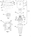
- FIG. 1 A preferred embodiment of the first assembly of the present invention, for taking dental impressions, is shown in Fig. 1 in an exploded perspective view, designated generally by numeral (100), and comprises an impression post (104), a coupler (106) for joining impression post (104) with a dental implant (102) previously affixed within a bone in the mouth of a patient, and an impression cap (108).
- first assembly (100) comprises impression post (104), coupler (106) and an impression cap (108), as described above, without dental implant (102).
- dental implant (102) is included in assembly (100).
- Dental implant (102) comprises a standard sized dental implant known in the art, and chosen by the dental practitioner according to his needs.
- Impression post (104) shown in the figure comprises an essentially cylindrical body portion (110) and a first end (112) comprising a male portion for insertion into the well of the female end (114) of dental implant (102).
- the dental implant comprises a male end for insertion into the well at the first end of the impression post.
- first end (112) comprises a hexagonal shape for fitting into corresponding female end (114), although any suitable corresponding shapes may be used.
- Second end (116) of impression post (104) comprises an essentially cylindrical female portion for receiving coupler (106) as described herein below.
- the outer circumference of second end (116) comprises a stepped curvature, as described in greater detail herein below.
- the length of impression post (104) is shorter than that of a typical prior art impression post.
- the length of the second end of a typical prior art impression post is 7mm
- second end (116) of impression post (104) of the present invention is preferably 2-3mm in length.
- the maximal diameter of the second end (116) is greater than its height (length) including the head of the coupler (124) when assembled. The reduced length reduces the difficulty in the withdrawal of the impression cap from the mouth as well as reduces the potential of shifting of impression cap (108) within the dental impression.
- coupler (106) comprises an elongated member (120) having a threaded distal end (122) for securing within the well of dental implant (102) and a wide diameter proximal end (124) for sitting on the proximal surface (126) of second end (116) of impression post (104) (see Fig. 2 ).
- the outer diameter of proximal end (124) is larger than the inner diameter of hollow longitudinal center (118) of impression post (104).
- Coupler (106) is manufactured from a material attractable by a magnetic force, such as metals.
- coupler (106) does not comprise wide diameter proximal end (124), rather, wide diameter proximal end (124) is integrally joined to second end (116) of impression post (104) at proximal surface (126), forming integral circumferential groove (154) as seen in Fig. 2 and described herein below.
- the present invention does not comprise a coupler as described and shown herein. Instead, the coupler comprises mechanical clips for maintaining the connection between impression post (104) and dental implant (102) (not shown).
- impression cap (108) is shown in a cross-sectional perspective view (see Fig. 3 ) and a cross-sectional side view, both taken along A-A of Fig. 1 (see Fig. 4 ).
- Impression cap (108) comprises a cavity (128) having at its base a mechanical force providing element (130), which, according to the invention comprises a magnet.
- the inner contour of a portion of cavity (128) comprises a combination of indentations and protrusions, as described in greater detail herein below.
- An elongated protrusion (132) extends longitudinally along opposing walls (only one shown in the figures) for slidingly fitting into the corresponding groove (134) in impression post (104), thereby enabling proper alignment of impression cap (108) with impression post (104).
- the distal inner diameter (136) of cavity (128) fits tightly around the proximal outer diameter (138) of body portion (110) of impression post (104).
- Distal circumferential lip (140) protrudes radially inward, proximally from the distal end of impression cap (108), for sitting on proximal surface (142) of body portion (110).
- Lip (140) is preferably a partial ring, and may consist of more than one section.
- a circumferential depression (144) in cavity (128) is formed between lip (140) and distal side wall (146) of cavity for joining with the model post, as described herein below.
- Distal side wall (146) sits flush with the distal side wall (148) of second end (116) of impression post (104).
- Proximal circumferential lip (150) situated proximally from distal side wall (146) and distally from proximal side wall (152), protrudes radially inward, for sitting on proximal surface (126) of second end (116) of impression post (104), and essentially secure within the circumferential groove (154) formed between proximal surface (126) and wide diameter proximal end (124) of coupler (106).
- Lip (150) is preferably a partial ring, and may consist of more than one section.
- Wide-diameter proximal end (124) of coupler (104) of first assembly (100) forms a shallow circumferential groove (154), which allows, a loose grasp on proximal lip (150).
- the main connecting force for securing impression cap (108) with impression post (104) is the magnetic force that attracts coupler (106) to magnet (130).
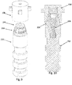
- impression post (104) is inserted through impression post (104) and is threadingly engaged with dental implant (102) such that impression post (104) and dental implant (102) are securely joined.
- Impression cap (108) is shown spaced apart therefrom.
- Handles (156) protrude radially from the outer surface of impression cap (108) for securing impression cap (108) when embedded within the impression material used to form a dental impression, as described herein below.
- two handles (156) are spaced essentially equidistantly around the outer surface of impression cap (108), however any number of handles (156) may be present.
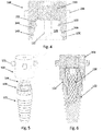
- FIG. 7 A preferred embodiment of the second assembly of the present invention, for forming dental models, is shown in Fig. 7 in an exploded perspective view, designated generally by numeral (200), and comprises a model post (204), a coupler (206) for joining impression model (204) with a dental analog (202), and impression cap (108).
- dental analog (202) is included as part of second assembly (200).
- Dental analog (202) comprises a standard sized dental analog known in the art, and chosen by the dental practitioner according to his needs.
- Dental analog (202) represents the dental implant (102) referred to in first assembly (100) when dental analog (202) is disposed within the stone dental model, described herein below.
- Distal portion (205) of analog (202) comprises an elongated cylindrical element (203), a portion of which is longitudinally cut out, for preventing analog rotation or shifting when in the dental model, as described herein below.
- Cylindrical rings (207) (preferably, at least one) having diameters wider than that of cylindrical element (203) are shown positioned around cylindrical element (203) for reinforcing the analog setting in the dental model, as described herein below.
- Model post (204) comprises an essentially cylindrical body portion (210) and a first end (212) comprises a male portion for insertion into the well within the female end (214) of dental analog (202).
- the dental implant comprises a male end for insertion into the well at the first end of the model post.
- first end (212) comprises a hexagonal shape for fitting into corresponding female end (214), although any suitable corresponding shapes may be used.
- Second end (216) of model post (204) comprises a cylindrical female portion for receiving coupler (206) as described herein below.
- the outer circumference of second end (216) comprises a stepped curvature, as described further herein below.
- second assembly coupler (206) is shown in second assembly (200) having an essentially identical structure as that of first assembly coupler (106) of first assembly (100), mutatis mutandis.
- the wide diameter proximal end (224) of coupler (206) is larger than that of wide diameter proximal end (124) of coupler (106) of first assembly (100), as described further herein below.
- Coupler (206) is an elongated member (220) having a threaded distal end (222) for securing to the inside of dental analog (202) and a wide diameter proximal end (224) for sitting on the proximal surface (226) of second end (216) of model post (204) (see Fig. 8 ).
- the outer diameter of proximal end (224) is larger than the inner diameter of hollow longitudinal center (218) of model post (204).
- Impression cap (108) is shown in second assembly (200) as the same component used as the impression cap (108) of first assembly (100), and described herein above.
- Elongated protrusion (132) extends longitudinally along opposing walls (only one shown in the figure) for slidingly fitting into the corresponding groove (234) in impression post (104), thereby enabling proper alignment of impression cap (108) with model post (204).
- the distal inner diameter (136) of cavity (128) fits tightly around the proximal outer diameter (238) of body portion (210) of model post (204).
- Distal circumferential lip (140) protrudes radially inward, proximally from the distal tip of impression cap (108), for sitting on proximal surface (242) of body portion (210).
- a circumferential depression (144) in cavity (128) is formed between lip (140) and distal side wall (146) of cavity, in which circumferential ring (243) around second end (216) of model post (204) is disposed.
- Distal side wall (146) sits flush with the proximal side wall (248) of second end (216) of model post (204).
- Lip (150) is preferably a partial ring, and may consist of more than one section.
- the larger diameter wide-diameter proximal end (224) of coupler (204) forms a deeper circumferential groove (254) than groove (154) formed in first assembly (100) (see Fig. 2 ). This is significant because the deeper groove (254) enables proximal lip (150) to be held tightly within groove (254), in contrast with the shallow groove (154) of first assembly (100) which allows a looser grasp on proximal lip (150).
- coupler (206) is inserted through model post (204) and threadingly engaged with dental analog (202) such that model post (204) and dental analog (202) are securely joined.
- Impression cap (108) is shown spaced apart therefrom.
- impression cap (108) is joined with model post (204), which is joined to dental analog (202), as seen in an assembled cross-sectional view cut longitudinally through assembly, in Fig. 10 .
- the method of the present invention for taking dental impressions and forming models using the kit of the present invention is described herein below and comprises the following steps:
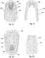
- FIG. 11 shows a cross-sectional front view of an impression tray (160) with impression material (162) surrounding impression cap (108) secured to impression post (104), with dental implant (102) positioned within bone (164).
- impression cap (108) is disengaged from impression post (104) by removing the tray from the mouth. See Fig. 12 , which schematically illustrates impression tray (160) with impression material (162) and embedded impression cap (108) disengaged from the impression post and removed from the mouth.
- the process until this point is performed by a dental practitioner such as a dentist, and the remainder of the process is typically performed by a dental technician, although any properly trained dental professional may perform any or all of the steps in the process.
- a dental practitioner such as a dentist
- the remainder of the process is typically performed by a dental technician, although any properly trained dental professional may perform any or all of the steps in the process.
- Second assembly (200) is provided for forming a dental model.
- Model post (204) is inserted into dental analog (202) and coupler (206) secures model post (204) thereto.
- Model post (204) is inserted into impression cap (108) and dental analog (202) is positioned within a tray, and the tray is at least partially filled with liquid plaster. After waiting a predetermined amount of time, the plaster material hardens, forming a stone dental model.
- FIG. 13 shows the cross-sectional front view of Fig. 12 , showing impression tray (160) with impression material (162) and embedded impression cap (108), in this figure, surrounding hardened plaster (262), forming a stone dental model and dental analog (202) embedded therein.
- impression cap (108) is disengaged from model post (204). See Fig. 14 , which schematically illustrates stone dental model (262) and embedded dental analog (202) disengaged from impression cap (108) and model post (204) of Fig. 13 .
- the method described herein is described for illustrative purposes only as utilizing a single kit comprising the first and second assemblies for forming a single dental impression and a single corresponding dental model of the single dental impression.
- the present invention is also intended to utilize multiple kits simultaneously in order to form multiple dental impressions and a corresponding dental model of the multiple dental impressions, mutatis mutandis.
Landscapes
- Health & Medical Sciences (AREA)
- Oral & Maxillofacial Surgery (AREA)
- Orthopedic Medicine & Surgery (AREA)
- Dentistry (AREA)
- Epidemiology (AREA)
- Life Sciences & Earth Sciences (AREA)
- Animal Behavior & Ethology (AREA)
- General Health & Medical Sciences (AREA)
- Public Health (AREA)
- Veterinary Medicine (AREA)
- Dental Prosthetics (AREA)
Claims (8)
- Kit destiné à être utilisé dans le processus de prise d'une empreinte dentaire et de formation d'un modèle dentaire, ledit kit comprenant un premier ensemble (100) pour former ladite empreinte dentaire et un deuxième ensemble (200) pour former ledit modèle dentaire, dans lequel ledit premier ensemble (100) comprend :a. un support d'empreinte (104) ;b. un premier coupleur (106) pour le couplage dudit support d'empreinte (104) à un implant dentaire (102) fixé à l'intérieur de la bouche ; etc. un capuchon d'empreinte (108) pour le positionnement sur ledit support d'empreinte (104) ;et dans lequel ledit deuxième ensemble (200) comprend :a. un support de modèle (204) ;b. un deuxième coupleur (206) pour le couplage dudit support de modèle (204) à un analogue dentaire (202) ; etc. ledit capuchon d'empreinte (108) ;dans lequel ledit capuchon d'empreinte (108) comprend un premier et deuxième moyen de fixation, tous deux pour la fixation sélective dudit capuchon d'empreinte (108) audit support d'empreinte (104) et audit support de modèle (204), ledit premier moyen de fixation comprenant un aimant (130) disposé à l'intérieur dudit capuchon d'empreinte (108) pour la fixation à un élément pouvant être attiré magnétiquement, et ledit deuxième moyen de fixation comprenant au moins une lèvre circonférentielle (140), (150) située à l'intérieur de la cavité (128) dudit capuchon d'empreinte (108) pour la fixation à l'intérieur d'au moins une rainure circonférentielle (154) formée par ledit premier coupleur (106) et ledit support d'empreinte (104), et pour la fixation à l'intérieur d'au moins une rainure circonférentielle (254) formée par ledit deuxième coupleur (106) et ledit support de modèle (204), respectivement.
- Kit selon la revendication 1, dans lequel le premier ensemble (100) comprend en outre l'implant dentaire (102).
- Kit selon la revendication 1, dans lequel le deuxième ensemble (200) comprend en outre l'analogue dentaire (202).
- Kit selon la revendication 1, dans lequel l'élément pouvant être attiré magnétiquement est le premier coupleur (106).
- Kit selon la revendication 1, dans lequel l'élément pouvant être attiré magnétiquement est le support d'empreinte (104).
- Kit selon la revendication 1, dans lequel le diamètre de l'extrémité proximale (124) du coupleur d'empreinte (106) est inférieur au diamètre de l'extrémité proximale (224) du coupleur de modèle (206).
- Kit selon la revendication 1, dans lequel le support d'empreinte (104) comprend une première extrémité (112), une deuxième extrémité (116) et une portion de corps centrale (110), dans lequel le diamètre maximum de ladite deuxième extrémité (116) est supérieur à sa hauteur tête (124) du coupleur (106) comprise lorsqu'il est assemblé.
- Procédé de formation d'une empreinte dentaire dans la bouche d'un patient ayant un implant dentaire fixé précédemment à l'intérieur de l'os, et d'un modèle dentaire comprenant les étapes suivantes :a. fourniture du premier ensemble (100) selon la revendication 1 ;b. positionnement du support d'empreinte (104) à l'intérieur dudit implant dentaire (102) ;c. fixation dudit support d'empreinte (104) audit implant dentaire (102) via le premier coupleur (106) ;d.positionnement et fixation du capuchon d'empreinte (108) au-dessus dudit support d'empreinte (104) ;e. fourniture d'un porte-empreinte (160) rempli au moins partiellement d'un matériau d'empreinte (162), et immersion d'au moins ledit capuchon d'empreinte (108) à l'intérieur dudit matériau d'empreinte (162) ;f. attente d'une quantité de temps prédéterminée pour le durcissement dudit matériau d'empreinte (162) ;g. dégagement dudit capuchon d'empreinte (108) dudit support d'empreinte (104) ;h. retrait dudit plateau (160) de ladite bouche ;i. fourniture du deuxième ensemble (200) selon la revendication 1 ;j. insertion du support de modèle (204) dans l'analogue dentaire (202) ;k. fixation dudit support de modèle (204) audit analogue dentaire (202) via le deuxième coupleur (206) ;l. insertion dudit support de modèle (204) dans ledit capuchon d'empreinte (108) ;m. positionnement dudit analogue dentaire (202) dans un plateau (160) en le remplissant au moins partiellement de plâtre liquide ;n. attente d'une quantité de temps prédéterminée pour le durcissement dudit plâtre ; eto. dégagement dudit capuchon d'empreinte (108) dudit support de modèle (204).
Priority Applications (2)
| Application Number | Priority Date | Filing Date | Title |
|---|---|---|---|
| EP14188629.1A EP3009100B1 (fr) | 2014-10-13 | 2014-10-13 | Kit et procédé permettant de former des modèles dentaires |
| IL236162A IL236162A0 (en) | 2014-10-13 | 2014-12-10 | A kit and method for taking dental coins and creating working models |
Applications Claiming Priority (1)
| Application Number | Priority Date | Filing Date | Title |
|---|---|---|---|
| EP14188629.1A EP3009100B1 (fr) | 2014-10-13 | 2014-10-13 | Kit et procédé permettant de former des modèles dentaires |
Publications (2)
| Publication Number | Publication Date |
|---|---|
| EP3009100A1 EP3009100A1 (fr) | 2016-04-20 |
| EP3009100B1 true EP3009100B1 (fr) | 2017-09-13 |
Family
ID=51690284
Family Applications (1)
| Application Number | Title | Priority Date | Filing Date |
|---|---|---|---|
| EP14188629.1A Not-in-force EP3009100B1 (fr) | 2014-10-13 | 2014-10-13 | Kit et procédé permettant de former des modèles dentaires |
Country Status (1)
| Country | Link |
|---|---|
| EP (1) | EP3009100B1 (fr) |
Cited By (1)
| Publication number | Priority date | Publication date | Assignee | Title |
|---|---|---|---|---|
| CN111601569A (zh) * | 2017-12-22 | 2020-08-28 | 医乐世医疗技术皮诺公司 | 牙科植入模拟物 |
Families Citing this family (2)
| Publication number | Priority date | Publication date | Assignee | Title |
|---|---|---|---|---|
| DE102019114009B4 (de) * | 2019-05-24 | 2022-04-28 | Kaub GmbH & Co. KG | Verfahren zur Herstellung einer Prothese, ein Abforminstrument zum Einbringen einer Abformmasse in den Mundraum eines Patienten sowie ein Handhabungswerkzeug zum Einbringen eines Verankerungsmagneten |
| LU101581B1 (fr) * | 2019-12-24 | 2021-06-28 | Baptista Augusto Andre | Pilier de cicatrisation anatomique implantaire provisoire |
Family Cites Families (5)
| Publication number | Priority date | Publication date | Assignee | Title |
|---|---|---|---|---|
| US5904483A (en) * | 1995-11-17 | 1999-05-18 | Wade; Curtis K. | Dental implant systems and methods |
| JP3658441B2 (ja) | 1996-02-26 | 2005-06-08 | 譲治 田中 | キャップ式磁性アタッチメント |
| US6283752B1 (en) * | 1998-07-13 | 2001-09-04 | Nobel Biocare Ab | Universal impression coping system |
| KR100428934B1 (ko) * | 2001-10-11 | 2004-04-29 | 주식회사 덴티움 | 임플란트 시술용 임프레션 코핑 |
| KR101091350B1 (ko) * | 2009-08-28 | 2011-12-07 | 동 욱 신 | 임플란트 시술용 임프레션 코핑 및 이를 이용한 인상 채득 방법 |
-
2014
- 2014-10-13 EP EP14188629.1A patent/EP3009100B1/fr not_active Not-in-force
Non-Patent Citations (1)
| Title |
|---|
| None * |
Cited By (1)
| Publication number | Priority date | Publication date | Assignee | Title |
|---|---|---|---|---|
| CN111601569A (zh) * | 2017-12-22 | 2020-08-28 | 医乐世医疗技术皮诺公司 | 牙科植入模拟物 |
Also Published As
| Publication number | Publication date |
|---|---|
| EP3009100A1 (fr) | 2016-04-20 |
Similar Documents
| Publication | Publication Date | Title |
|---|---|---|
| JP4662710B2 (ja) | 改良された印象採得のための構成要素 | |
| JP4276540B2 (ja) | 改良した印象採得のための構成要素および方法 | |
| ES2881468T3 (es) | Posicionamiento e instalación de dispositivos de taladrado quirúrgicos y dispositivos y sistemas relacionados | |
| JP2010172703A (ja) | 歯科インプラントのためのインプレッションポスト | |
| EP3057529B1 (fr) | Copie d'implant dentaire | |
| EP3009100B1 (fr) | Kit et procédé permettant de former des modèles dentaires | |
| KR101172838B1 (ko) | 멀티 어버트먼트 장치 | |
| US9655696B2 (en) | Kit and method for taking dental impressions and forming dental models | |
| KR101869348B1 (ko) | 임플란트 고정체의 제조방법 및 그에 의한 임플란트 고정체 | |
| US20180147036A1 (en) | Method for positioning prosthetic teeth in a denture base | |
| AU2018204181B2 (en) | Combination impression coping and scan body | |
| WO2014049589A1 (fr) | Système et procédé de prise d'empreintes dentaires | |
| US10905528B2 (en) | System and method for registering implant orientation directly from a dental impression | |
| EP3914187B1 (fr) | Élément d'accouplement pour applications dentaires et kit correspondant | |
| AU2019217590B2 (en) | Implant comprising a radially enlarged post on the support structure, soft tissue displacement system, manufacturing process and planning process for manufacturing an implant | |
| CN107278143B (zh) | 具有横向部件的植入物类似物 | |
| US20210282894A1 (en) | Drill jig for an oral surgery intervention | |
| EP3298983B1 (fr) | Procédé d'enregistrement d'orientation d'implants directement à partir d'une empreinte dentaire | |
| US12484997B2 (en) | Implant analogs and methods | |
| US20220133442A1 (en) | Impression post for connection to a dental implant | |
| EP4044960B1 (fr) | Barre dentaire | |
| US20080032262A1 (en) | Dental implant system and method thereof | |
| WO2013030839A1 (fr) | Procédé d'attache et de détachement de constructions dentaires et dispositif associé | |
| US20100233656A1 (en) | Dual function system for dental implants | |
| RU2774601C1 (ru) | Система зубного имплантата |
Legal Events
| Date | Code | Title | Description |
|---|---|---|---|
| PUAI | Public reference made under article 153(3) epc to a published international application that has entered the european phase |
Free format text: ORIGINAL CODE: 0009012 |
|
| AK | Designated contracting states |
Kind code of ref document: A1 Designated state(s): AL AT BE BG CH CY CZ DE DK EE ES FI FR GB GR HR HU IE IS IT LI LT LU LV MC MK MT NL NO PL PT RO RS SE SI SK SM TR |
|
| AX | Request for extension of the european patent |
Extension state: BA ME |
|
| 17P | Request for examination filed |
Effective date: 20160405 |
|
| RBV | Designated contracting states (corrected) |
Designated state(s): AL AT BE BG CH CY CZ DE DK EE ES FI FR GB GR HR HU IE IS IT LI LT LU LV MC MK MT NL NO PL PT RO RS SE SI SK SM TR |
|
| STAA | Information on the status of an ep patent application or granted ep patent |
Free format text: STATUS: EXAMINATION IS IN PROGRESS |
|
| 17Q | First examination report despatched |
Effective date: 20161102 |
|
| GRAP | Despatch of communication of intention to grant a patent |
Free format text: ORIGINAL CODE: EPIDOSNIGR1 |
|
| STAA | Information on the status of an ep patent application or granted ep patent |
Free format text: STATUS: GRANT OF PATENT IS INTENDED |
|
| INTG | Intention to grant announced |
Effective date: 20170510 |
|
| GRAS | Grant fee paid |
Free format text: ORIGINAL CODE: EPIDOSNIGR3 |
|
| GRAA | (expected) grant |
Free format text: ORIGINAL CODE: 0009210 |
|
| STAA | Information on the status of an ep patent application or granted ep patent |
Free format text: STATUS: THE PATENT HAS BEEN GRANTED |
|
| AK | Designated contracting states |
Kind code of ref document: B1 Designated state(s): AL AT BE BG CH CY CZ DE DK EE ES FI FR GB GR HR HU IE IS IT LI LT LU LV MC MK MT NL NO PL PT RO RS SE SI SK SM TR |
|
| REG | Reference to a national code |
Ref country code: GB Ref legal event code: FG4D |
|
| REG | Reference to a national code |
Ref country code: CH Ref legal event code: EP |
|
| REG | Reference to a national code |
Ref country code: IE Ref legal event code: FG4D |
|
| REG | Reference to a national code |
Ref country code: AT Ref legal event code: REF Ref document number: 927415 Country of ref document: AT Kind code of ref document: T Effective date: 20171015 |
|
| REG | Reference to a national code |
Ref country code: DE Ref legal event code: R096 Ref document number: 602014014476 Country of ref document: DE |
|
| REG | Reference to a national code |
Ref country code: FR Ref legal event code: PLFP Year of fee payment: 4 |
|
| REG | Reference to a national code |
Ref country code: NL Ref legal event code: MP Effective date: 20170913 |
|
| REG | Reference to a national code |
Ref country code: LT Ref legal event code: MG4D |
|
| PG25 | Lapsed in a contracting state [announced via postgrant information from national office to epo] |
Ref country code: HR Free format text: LAPSE BECAUSE OF FAILURE TO SUBMIT A TRANSLATION OF THE DESCRIPTION OR TO PAY THE FEE WITHIN THE PRESCRIBED TIME-LIMIT Effective date: 20170913 Ref country code: FI Free format text: LAPSE BECAUSE OF FAILURE TO SUBMIT A TRANSLATION OF THE DESCRIPTION OR TO PAY THE FEE WITHIN THE PRESCRIBED TIME-LIMIT Effective date: 20170913 Ref country code: LT Free format text: LAPSE BECAUSE OF FAILURE TO SUBMIT A TRANSLATION OF THE DESCRIPTION OR TO PAY THE FEE WITHIN THE PRESCRIBED TIME-LIMIT Effective date: 20170913 Ref country code: SE Free format text: LAPSE BECAUSE OF FAILURE TO SUBMIT A TRANSLATION OF THE DESCRIPTION OR TO PAY THE FEE WITHIN THE PRESCRIBED TIME-LIMIT Effective date: 20170913 Ref country code: NO Free format text: LAPSE BECAUSE OF FAILURE TO SUBMIT A TRANSLATION OF THE DESCRIPTION OR TO PAY THE FEE WITHIN THE PRESCRIBED TIME-LIMIT Effective date: 20171213 |
|
| PGFP | Annual fee paid to national office [announced via postgrant information from national office to epo] |
Ref country code: FR Payment date: 20171108 Year of fee payment: 4 Ref country code: DE Payment date: 20171106 Year of fee payment: 4 |
|
| REG | Reference to a national code |
Ref country code: AT Ref legal event code: MK05 Ref document number: 927415 Country of ref document: AT Kind code of ref document: T Effective date: 20170913 |
|
| PG25 | Lapsed in a contracting state [announced via postgrant information from national office to epo] |
Ref country code: LV Free format text: LAPSE BECAUSE OF FAILURE TO SUBMIT A TRANSLATION OF THE DESCRIPTION OR TO PAY THE FEE WITHIN THE PRESCRIBED TIME-LIMIT Effective date: 20170913 Ref country code: GR Free format text: LAPSE BECAUSE OF FAILURE TO SUBMIT A TRANSLATION OF THE DESCRIPTION OR TO PAY THE FEE WITHIN THE PRESCRIBED TIME-LIMIT Effective date: 20171214 Ref country code: ES Free format text: LAPSE BECAUSE OF FAILURE TO SUBMIT A TRANSLATION OF THE DESCRIPTION OR TO PAY THE FEE WITHIN THE PRESCRIBED TIME-LIMIT Effective date: 20170913 Ref country code: BG Free format text: LAPSE BECAUSE OF FAILURE TO SUBMIT A TRANSLATION OF THE DESCRIPTION OR TO PAY THE FEE WITHIN THE PRESCRIBED TIME-LIMIT Effective date: 20171213 Ref country code: RS Free format text: LAPSE BECAUSE OF FAILURE TO SUBMIT A TRANSLATION OF THE DESCRIPTION OR TO PAY THE FEE WITHIN THE PRESCRIBED TIME-LIMIT Effective date: 20170913 |
|
| PG25 | Lapsed in a contracting state [announced via postgrant information from national office to epo] |
Ref country code: NL Free format text: LAPSE BECAUSE OF FAILURE TO SUBMIT A TRANSLATION OF THE DESCRIPTION OR TO PAY THE FEE WITHIN THE PRESCRIBED TIME-LIMIT Effective date: 20170913 |
|
| PG25 | Lapsed in a contracting state [announced via postgrant information from national office to epo] |
Ref country code: RO Free format text: LAPSE BECAUSE OF FAILURE TO SUBMIT A TRANSLATION OF THE DESCRIPTION OR TO PAY THE FEE WITHIN THE PRESCRIBED TIME-LIMIT Effective date: 20170913 Ref country code: CZ Free format text: LAPSE BECAUSE OF FAILURE TO SUBMIT A TRANSLATION OF THE DESCRIPTION OR TO PAY THE FEE WITHIN THE PRESCRIBED TIME-LIMIT Effective date: 20170913 Ref country code: PL Free format text: LAPSE BECAUSE OF FAILURE TO SUBMIT A TRANSLATION OF THE DESCRIPTION OR TO PAY THE FEE WITHIN THE PRESCRIBED TIME-LIMIT Effective date: 20170913 |
|
| PG25 | Lapsed in a contracting state [announced via postgrant information from national office to epo] |
Ref country code: SK Free format text: LAPSE BECAUSE OF FAILURE TO SUBMIT A TRANSLATION OF THE DESCRIPTION OR TO PAY THE FEE WITHIN THE PRESCRIBED TIME-LIMIT Effective date: 20170913 Ref country code: EE Free format text: LAPSE BECAUSE OF FAILURE TO SUBMIT A TRANSLATION OF THE DESCRIPTION OR TO PAY THE FEE WITHIN THE PRESCRIBED TIME-LIMIT Effective date: 20170913 Ref country code: AT Free format text: LAPSE BECAUSE OF FAILURE TO SUBMIT A TRANSLATION OF THE DESCRIPTION OR TO PAY THE FEE WITHIN THE PRESCRIBED TIME-LIMIT Effective date: 20170913 Ref country code: IS Free format text: LAPSE BECAUSE OF FAILURE TO SUBMIT A TRANSLATION OF THE DESCRIPTION OR TO PAY THE FEE WITHIN THE PRESCRIBED TIME-LIMIT Effective date: 20180113 Ref country code: SM Free format text: LAPSE BECAUSE OF FAILURE TO SUBMIT A TRANSLATION OF THE DESCRIPTION OR TO PAY THE FEE WITHIN THE PRESCRIBED TIME-LIMIT Effective date: 20170913 Ref country code: IT Free format text: LAPSE BECAUSE OF FAILURE TO SUBMIT A TRANSLATION OF THE DESCRIPTION OR TO PAY THE FEE WITHIN THE PRESCRIBED TIME-LIMIT Effective date: 20170913 |
|
| REG | Reference to a national code |
Ref country code: CH Ref legal event code: PL |
|
| REG | Reference to a national code |
Ref country code: DE Ref legal event code: R097 Ref document number: 602014014476 Country of ref document: DE |
|
| PG25 | Lapsed in a contracting state [announced via postgrant information from national office to epo] |
Ref country code: MC Free format text: LAPSE BECAUSE OF FAILURE TO SUBMIT A TRANSLATION OF THE DESCRIPTION OR TO PAY THE FEE WITHIN THE PRESCRIBED TIME-LIMIT Effective date: 20170913 |
|
| PLBE | No opposition filed within time limit |
Free format text: ORIGINAL CODE: 0009261 |
|
| STAA | Information on the status of an ep patent application or granted ep patent |
Free format text: STATUS: NO OPPOSITION FILED WITHIN TIME LIMIT |
|
| REG | Reference to a national code |
Ref country code: IE Ref legal event code: MM4A |
|
| PG25 | Lapsed in a contracting state [announced via postgrant information from national office to epo] |
Ref country code: LU Free format text: LAPSE BECAUSE OF NON-PAYMENT OF DUE FEES Effective date: 20171013 Ref country code: CH Free format text: LAPSE BECAUSE OF NON-PAYMENT OF DUE FEES Effective date: 20171031 Ref country code: DK Free format text: LAPSE BECAUSE OF FAILURE TO SUBMIT A TRANSLATION OF THE DESCRIPTION OR TO PAY THE FEE WITHIN THE PRESCRIBED TIME-LIMIT Effective date: 20170913 Ref country code: LI Free format text: LAPSE BECAUSE OF NON-PAYMENT OF DUE FEES Effective date: 20171031 |
|
| 26N | No opposition filed |
Effective date: 20180614 |
|
| REG | Reference to a national code |
Ref country code: BE Ref legal event code: MM Effective date: 20171031 |
|
| PG25 | Lapsed in a contracting state [announced via postgrant information from national office to epo] |
Ref country code: BE Free format text: LAPSE BECAUSE OF NON-PAYMENT OF DUE FEES Effective date: 20171031 |
|
| PG25 | Lapsed in a contracting state [announced via postgrant information from national office to epo] |
Ref country code: MT Free format text: LAPSE BECAUSE OF NON-PAYMENT OF DUE FEES Effective date: 20171013 |
|
| PG25 | Lapsed in a contracting state [announced via postgrant information from national office to epo] |
Ref country code: IE Free format text: LAPSE BECAUSE OF NON-PAYMENT OF DUE FEES Effective date: 20171013 |
|
| PG25 | Lapsed in a contracting state [announced via postgrant information from national office to epo] |
Ref country code: SI Free format text: LAPSE BECAUSE OF FAILURE TO SUBMIT A TRANSLATION OF THE DESCRIPTION OR TO PAY THE FEE WITHIN THE PRESCRIBED TIME-LIMIT Effective date: 20170913 |
|
| REG | Reference to a national code |
Ref country code: DE Ref legal event code: R119 Ref document number: 602014014476 Country of ref document: DE |
|
| GBPC | Gb: european patent ceased through non-payment of renewal fee |
Effective date: 20181013 |
|
| PG25 | Lapsed in a contracting state [announced via postgrant information from national office to epo] |
Ref country code: HU Free format text: LAPSE BECAUSE OF FAILURE TO SUBMIT A TRANSLATION OF THE DESCRIPTION OR TO PAY THE FEE WITHIN THE PRESCRIBED TIME-LIMIT; INVALID AB INITIO Effective date: 20141013 |
|
| PG25 | Lapsed in a contracting state [announced via postgrant information from national office to epo] |
Ref country code: DE Free format text: LAPSE BECAUSE OF NON-PAYMENT OF DUE FEES Effective date: 20190501 |
|
| PG25 | Lapsed in a contracting state [announced via postgrant information from national office to epo] |
Ref country code: FR Free format text: LAPSE BECAUSE OF NON-PAYMENT OF DUE FEES Effective date: 20181031 |
|
| PG25 | Lapsed in a contracting state [announced via postgrant information from national office to epo] |
Ref country code: GB Free format text: LAPSE BECAUSE OF NON-PAYMENT OF DUE FEES Effective date: 20181013 Ref country code: CY Free format text: LAPSE BECAUSE OF FAILURE TO SUBMIT A TRANSLATION OF THE DESCRIPTION OR TO PAY THE FEE WITHIN THE PRESCRIBED TIME-LIMIT Effective date: 20170913 |
|
| PG25 | Lapsed in a contracting state [announced via postgrant information from national office to epo] |
Ref country code: MK Free format text: LAPSE BECAUSE OF FAILURE TO SUBMIT A TRANSLATION OF THE DESCRIPTION OR TO PAY THE FEE WITHIN THE PRESCRIBED TIME-LIMIT Effective date: 20170913 |
|
| PG25 | Lapsed in a contracting state [announced via postgrant information from national office to epo] |
Ref country code: TR Free format text: LAPSE BECAUSE OF FAILURE TO SUBMIT A TRANSLATION OF THE DESCRIPTION OR TO PAY THE FEE WITHIN THE PRESCRIBED TIME-LIMIT Effective date: 20170913 |
|
| PG25 | Lapsed in a contracting state [announced via postgrant information from national office to epo] |
Ref country code: PT Free format text: LAPSE BECAUSE OF FAILURE TO SUBMIT A TRANSLATION OF THE DESCRIPTION OR TO PAY THE FEE WITHIN THE PRESCRIBED TIME-LIMIT Effective date: 20170913 |
|
| PG25 | Lapsed in a contracting state [announced via postgrant information from national office to epo] |
Ref country code: AL Free format text: LAPSE BECAUSE OF FAILURE TO SUBMIT A TRANSLATION OF THE DESCRIPTION OR TO PAY THE FEE WITHIN THE PRESCRIBED TIME-LIMIT Effective date: 20170913 |