EP3009256A1 - Structure comprenant un adhésif durcissant à la lumière et procédé associé d'assemblage et de durcissement de celle-ci - Google Patents
Structure comprenant un adhésif durcissant à la lumière et procédé associé d'assemblage et de durcissement de celle-ci Download PDFInfo
- Publication number
- EP3009256A1 EP3009256A1 EP15183973.5A EP15183973A EP3009256A1 EP 3009256 A1 EP3009256 A1 EP 3009256A1 EP 15183973 A EP15183973 A EP 15183973A EP 3009256 A1 EP3009256 A1 EP 3009256A1
- Authority
- EP
- European Patent Office
- Prior art keywords
- light
- curable adhesive
- guiding members
- structural component
- light guiding
- Prior art date
- Legal status (The legal status is an assumption and is not a legal conclusion. Google has not performed a legal analysis and makes no representation as to the accuracy of the status listed.)
- Granted
Links
Images



Classifications
-
- B—PERFORMING OPERATIONS; TRANSPORTING
- B32—LAYERED PRODUCTS
- B32B—LAYERED PRODUCTS, i.e. PRODUCTS BUILT-UP OF STRATA OF FLAT OR NON-FLAT, e.g. CELLULAR OR HONEYCOMB, FORM
- B32B37/00—Methods or apparatus for laminating, e.g. by curing or by ultrasonic bonding
- B32B37/14—Methods or apparatus for laminating, e.g. by curing or by ultrasonic bonding characterised by the properties of the layers
- B32B37/16—Methods or apparatus for laminating, e.g. by curing or by ultrasonic bonding characterised by the properties of the layers with all layers existing as coherent layers before laminating
- B32B37/18—Methods or apparatus for laminating, e.g. by curing or by ultrasonic bonding characterised by the properties of the layers with all layers existing as coherent layers before laminating involving the assembly of discrete sheets or panels only
-
- B—PERFORMING OPERATIONS; TRANSPORTING
- B29—WORKING OF PLASTICS; WORKING OF SUBSTANCES IN A PLASTIC STATE IN GENERAL
- B29C—SHAPING OR JOINING OF PLASTICS; SHAPING OF MATERIAL IN A PLASTIC STATE, NOT OTHERWISE PROVIDED FOR; AFTER-TREATMENT OF THE SHAPED PRODUCTS, e.g. REPAIRING
- B29C65/00—Joining or sealing of preformed parts, e.g. welding of plastics materials; Apparatus therefor
- B29C65/02—Joining or sealing of preformed parts, e.g. welding of plastics materials; Apparatus therefor by heating, with or without pressure
- B29C65/14—Joining or sealing of preformed parts, e.g. welding of plastics materials; Apparatus therefor by heating, with or without pressure using wave energy, i.e. electromagnetic radiation, or particle radiation
- B29C65/1429—Joining or sealing of preformed parts, e.g. welding of plastics materials; Apparatus therefor by heating, with or without pressure using wave energy, i.e. electromagnetic radiation, or particle radiation characterised by the way of heating the interface
- B29C65/1464—Joining or sealing of preformed parts, e.g. welding of plastics materials; Apparatus therefor by heating, with or without pressure using wave energy, i.e. electromagnetic radiation, or particle radiation characterised by the way of heating the interface making use of several radiators
- B29C65/1467—Joining or sealing of preformed parts, e.g. welding of plastics materials; Apparatus therefor by heating, with or without pressure using wave energy, i.e. electromagnetic radiation, or particle radiation characterised by the way of heating the interface making use of several radiators at the same time, i.e. simultaneous welding
-
- B—PERFORMING OPERATIONS; TRANSPORTING
- B29—WORKING OF PLASTICS; WORKING OF SUBSTANCES IN A PLASTIC STATE IN GENERAL
- B29C—SHAPING OR JOINING OF PLASTICS; SHAPING OF MATERIAL IN A PLASTIC STATE, NOT OTHERWISE PROVIDED FOR; AFTER-TREATMENT OF THE SHAPED PRODUCTS, e.g. REPAIRING
- B29C35/00—Heating, cooling or curing, e.g. crosslinking or vulcanising; Apparatus therefor
- B29C35/02—Heating or curing, e.g. crosslinking or vulcanizing during moulding, e.g. in a mould
- B29C35/0272—Heating or curing, e.g. crosslinking or vulcanizing during moulding, e.g. in a mould using lost heating elements, i.e. heating means incorporated and remaining in the formed article
-
- B—PERFORMING OPERATIONS; TRANSPORTING
- B29—WORKING OF PLASTICS; WORKING OF SUBSTANCES IN A PLASTIC STATE IN GENERAL
- B29C—SHAPING OR JOINING OF PLASTICS; SHAPING OF MATERIAL IN A PLASTIC STATE, NOT OTHERWISE PROVIDED FOR; AFTER-TREATMENT OF THE SHAPED PRODUCTS, e.g. REPAIRING
- B29C65/00—Joining or sealing of preformed parts, e.g. welding of plastics materials; Apparatus therefor
- B29C65/02—Joining or sealing of preformed parts, e.g. welding of plastics materials; Apparatus therefor by heating, with or without pressure
- B29C65/14—Joining or sealing of preformed parts, e.g. welding of plastics materials; Apparatus therefor by heating, with or without pressure using wave energy, i.e. electromagnetic radiation, or particle radiation
- B29C65/1487—Joining or sealing of preformed parts, e.g. welding of plastics materials; Apparatus therefor by heating, with or without pressure using wave energy, i.e. electromagnetic radiation, or particle radiation making use of light guides
- B29C65/149—Joining or sealing of preformed parts, e.g. welding of plastics materials; Apparatus therefor by heating, with or without pressure using wave energy, i.e. electromagnetic radiation, or particle radiation making use of light guides being a part of the joined article
-
- B—PERFORMING OPERATIONS; TRANSPORTING
- B29—WORKING OF PLASTICS; WORKING OF SUBSTANCES IN A PLASTIC STATE IN GENERAL
- B29C—SHAPING OR JOINING OF PLASTICS; SHAPING OF MATERIAL IN A PLASTIC STATE, NOT OTHERWISE PROVIDED FOR; AFTER-TREATMENT OF THE SHAPED PRODUCTS, e.g. REPAIRING
- B29C65/00—Joining or sealing of preformed parts, e.g. welding of plastics materials; Apparatus therefor
- B29C65/48—Joining or sealing of preformed parts, e.g. welding of plastics materials; Apparatus therefor using adhesives, i.e. using supplementary joining material; solvent bonding
- B29C65/4805—Joining or sealing of preformed parts, e.g. welding of plastics materials; Apparatus therefor using adhesives, i.e. using supplementary joining material; solvent bonding characterised by the type of adhesives
- B29C65/483—Reactive adhesives, e.g. chemically curing adhesives
- B29C65/4845—Radiation curing adhesives, e.g. UV light curing adhesives
-
- B—PERFORMING OPERATIONS; TRANSPORTING
- B29—WORKING OF PLASTICS; WORKING OF SUBSTANCES IN A PLASTIC STATE IN GENERAL
- B29C—SHAPING OR JOINING OF PLASTICS; SHAPING OF MATERIAL IN A PLASTIC STATE, NOT OTHERWISE PROVIDED FOR; AFTER-TREATMENT OF THE SHAPED PRODUCTS, e.g. REPAIRING
- B29C66/00—General aspects of processes or apparatus for joining preformed parts
- B29C66/01—General aspects dealing with the joint area or with the area to be joined
- B29C66/05—Particular design of joint configurations
- B29C66/10—Particular design of joint configurations particular design of the joint cross-sections
- B29C66/11—Joint cross-sections comprising a single joint-segment, i.e. one of the parts to be joined comprising a single joint-segment in the joint cross-section
- B29C66/112—Single lapped joints
- B29C66/1122—Single lap to lap joints, i.e. overlap joints
-
- B—PERFORMING OPERATIONS; TRANSPORTING
- B29—WORKING OF PLASTICS; WORKING OF SUBSTANCES IN A PLASTIC STATE IN GENERAL
- B29C—SHAPING OR JOINING OF PLASTICS; SHAPING OF MATERIAL IN A PLASTIC STATE, NOT OTHERWISE PROVIDED FOR; AFTER-TREATMENT OF THE SHAPED PRODUCTS, e.g. REPAIRING
- B29C66/00—General aspects of processes or apparatus for joining preformed parts
- B29C66/50—General aspects of joining tubular articles; General aspects of joining long products, i.e. bars or profiled elements; General aspects of joining single elements to tubular articles, hollow articles or bars; General aspects of joining several hollow-preforms to form hollow or tubular articles
- B29C66/51—Joining tubular articles, profiled elements or bars; Joining single elements to tubular articles, hollow articles or bars; Joining several hollow-preforms to form hollow or tubular articles
- B29C66/53—Joining single elements to tubular articles, hollow articles or bars
- B29C66/532—Joining single elements to the wall of tubular articles, hollow articles or bars
- B29C66/5326—Joining single elements to the wall of tubular articles, hollow articles or bars said single elements being substantially flat
-
- B—PERFORMING OPERATIONS; TRANSPORTING
- B29—WORKING OF PLASTICS; WORKING OF SUBSTANCES IN A PLASTIC STATE IN GENERAL
- B29C—SHAPING OR JOINING OF PLASTICS; SHAPING OF MATERIAL IN A PLASTIC STATE, NOT OTHERWISE PROVIDED FOR; AFTER-TREATMENT OF THE SHAPED PRODUCTS, e.g. REPAIRING
- B29C73/00—Repairing of articles made from plastics or substances in a plastic state, e.g. of articles shaped or produced by using techniques covered by this subclass or subclass B29D
- B29C73/04—Repairing of articles made from plastics or substances in a plastic state, e.g. of articles shaped or produced by using techniques covered by this subclass or subclass B29D using preformed elements
- B29C73/10—Repairing of articles made from plastics or substances in a plastic state, e.g. of articles shaped or produced by using techniques covered by this subclass or subclass B29D using preformed elements using patches sealing on the surface of the article
-
- B—PERFORMING OPERATIONS; TRANSPORTING
- B32—LAYERED PRODUCTS
- B32B—LAYERED PRODUCTS, i.e. PRODUCTS BUILT-UP OF STRATA OF FLAT OR NON-FLAT, e.g. CELLULAR OR HONEYCOMB, FORM
- B32B37/00—Methods or apparatus for laminating, e.g. by curing or by ultrasonic bonding
- B32B37/12—Methods or apparatus for laminating, e.g. by curing or by ultrasonic bonding characterised by using adhesives
- B32B37/1284—Application of adhesive
-
- B—PERFORMING OPERATIONS; TRANSPORTING
- B32—LAYERED PRODUCTS
- B32B—LAYERED PRODUCTS, i.e. PRODUCTS BUILT-UP OF STRATA OF FLAT OR NON-FLAT, e.g. CELLULAR OR HONEYCOMB, FORM
- B32B38/00—Ancillary operations in connection with laminating processes
- B32B38/0008—Electrical discharge treatment, e.g. corona, plasma treatment; wave energy or particle radiation
-
- B—PERFORMING OPERATIONS; TRANSPORTING
- B29—WORKING OF PLASTICS; WORKING OF SUBSTANCES IN A PLASTIC STATE IN GENERAL
- B29C—SHAPING OR JOINING OF PLASTICS; SHAPING OF MATERIAL IN A PLASTIC STATE, NOT OTHERWISE PROVIDED FOR; AFTER-TREATMENT OF THE SHAPED PRODUCTS, e.g. REPAIRING
- B29C35/00—Heating, cooling or curing, e.g. crosslinking or vulcanising; Apparatus therefor
- B29C35/02—Heating or curing, e.g. crosslinking or vulcanizing during moulding, e.g. in a mould
- B29C35/08—Heating or curing, e.g. crosslinking or vulcanizing during moulding, e.g. in a mould by wave energy or particle radiation
- B29C35/0805—Heating or curing, e.g. crosslinking or vulcanizing during moulding, e.g. in a mould by wave energy or particle radiation using electromagnetic radiation
- B29C2035/0827—Heating or curing, e.g. crosslinking or vulcanizing during moulding, e.g. in a mould by wave energy or particle radiation using electromagnetic radiation using UV radiation
-
- B—PERFORMING OPERATIONS; TRANSPORTING
- B29—WORKING OF PLASTICS; WORKING OF SUBSTANCES IN A PLASTIC STATE IN GENERAL
- B29C—SHAPING OR JOINING OF PLASTICS; SHAPING OF MATERIAL IN A PLASTIC STATE, NOT OTHERWISE PROVIDED FOR; AFTER-TREATMENT OF THE SHAPED PRODUCTS, e.g. REPAIRING
- B29C65/00—Joining or sealing of preformed parts, e.g. welding of plastics materials; Apparatus therefor
- B29C65/02—Joining or sealing of preformed parts, e.g. welding of plastics materials; Apparatus therefor by heating, with or without pressure
- B29C65/14—Joining or sealing of preformed parts, e.g. welding of plastics materials; Apparatus therefor by heating, with or without pressure using wave energy, i.e. electromagnetic radiation, or particle radiation
- B29C65/1403—Joining or sealing of preformed parts, e.g. welding of plastics materials; Apparatus therefor by heating, with or without pressure using wave energy, i.e. electromagnetic radiation, or particle radiation characterised by the type of electromagnetic or particle radiation
- B29C65/1406—Ultraviolet [UV] radiation
-
- B—PERFORMING OPERATIONS; TRANSPORTING
- B29—WORKING OF PLASTICS; WORKING OF SUBSTANCES IN A PLASTIC STATE IN GENERAL
- B29C—SHAPING OR JOINING OF PLASTICS; SHAPING OF MATERIAL IN A PLASTIC STATE, NOT OTHERWISE PROVIDED FOR; AFTER-TREATMENT OF THE SHAPED PRODUCTS, e.g. REPAIRING
- B29C66/00—General aspects of processes or apparatus for joining preformed parts
- B29C66/70—General aspects of processes or apparatus for joining preformed parts characterised by the composition, physical properties or the structure of the material of the parts to be joined; Joining with non-plastics material
- B29C66/72—General aspects of processes or apparatus for joining preformed parts characterised by the composition, physical properties or the structure of the material of the parts to be joined; Joining with non-plastics material characterised by the structure of the material of the parts to be joined
- B29C66/721—Fibre-reinforced materials
-
- B—PERFORMING OPERATIONS; TRANSPORTING
- B29—WORKING OF PLASTICS; WORKING OF SUBSTANCES IN A PLASTIC STATE IN GENERAL
- B29L—INDEXING SCHEME ASSOCIATED WITH SUBCLASS B29C, RELATING TO PARTICULAR ARTICLES
- B29L2031/00—Other particular articles
- B29L2031/30—Vehicles, e.g. ships or aircraft, or body parts thereof
-
- B—PERFORMING OPERATIONS; TRANSPORTING
- B29—WORKING OF PLASTICS; WORKING OF SUBSTANCES IN A PLASTIC STATE IN GENERAL
- B29L—INDEXING SCHEME ASSOCIATED WITH SUBCLASS B29C, RELATING TO PARTICULAR ARTICLES
- B29L2031/00—Other particular articles
- B29L2031/30—Vehicles, e.g. ships or aircraft, or body parts thereof
- B29L2031/3076—Aircrafts
-
- B—PERFORMING OPERATIONS; TRANSPORTING
- B32—LAYERED PRODUCTS
- B32B—LAYERED PRODUCTS, i.e. PRODUCTS BUILT-UP OF STRATA OF FLAT OR NON-FLAT, e.g. CELLULAR OR HONEYCOMB, FORM
- B32B37/00—Methods or apparatus for laminating, e.g. by curing or by ultrasonic bonding
- B32B37/12—Methods or apparatus for laminating, e.g. by curing or by ultrasonic bonding characterised by using adhesives
- B32B2037/1253—Methods or apparatus for laminating, e.g. by curing or by ultrasonic bonding characterised by using adhesives curable adhesive
Definitions
- An example embodiment of the present disclosure relates generally to the assembly and curing of a structure and, more particularly, to the assembly and curing of a structure that includes a light-curable adhesive.
- Thermal adhesives are commonly utilized in the fabrication of various structures, such as composite structures, and in the bonding of doublers and patches to an underlying structure.
- a composite structure or a doubler or patch that is being bonded to an underlying structure must generally be subjected to substantially elevated temperatures and pressures for a period of time, such as several hours.
- the application of the substantially elevated temperature and pressures may be cumbersome and may increase the overall manufacturing or repair costs, while the time required to cure the thermal adhesive may slow the manufacturing or repair process.
- a composite structure may be formed of a plurality of plies.
- Each ply may include a plurality of fibers, such as graphite fibers or glass fibers.
- Each ply may be preimpregnated with a thermal adhesive or the plies may be vacuum impregnated with a thermal adhesive prior to layup of the plies.
- the composite plies may be laid up one upon another and may then be cured in order to integrate the composite plies and form the resulting composite structure.
- the composite plies may be placed in a vacuum bag and the vacuum bagged assembly may, in turn, be placed in an autoclave. The autoclave may heat the composite plies and the thermal adhesive, while pressure is applied thereto via the vacuum bag.
- the thermal adhesive may be cured such that once removed from the autoclave and the vacuum bag, the resulting composite structure is integral, but at the expense of increased manufacturing costs and time.
- a doubler or patch may be bonded to an underlying structure, such as a portion of an aircraft, in order to reinforce the underlying structure, affect a repair of the structure or the like.
- a thermal adhesive may be applied to the underlying structure and the doubler or patch may be positioned upon the adhesive. The thermal adhesive may then be cured by applying a vacuum bag directly over the repair or by applying a caul plate over the patch and applying a vacuum bag over the repair area and sealing the vacuum bag to the underlying structure, such as by using tacky tape, and then subjecting the doubler or patch to vacuum and the thermal adhesive to elevated temperatures and pressure.
- a heat blanket may be placed over the vacuum bag covering the doubler or patch and a vacuum may be used to apply pressure to the doubler or patch to urge the doubler or patch toward the underlying structure.
- the thermal adhesive may have been cured such that the pressure may be eliminated and the thermal blanket may be removed to uncover the doubler or patch bonded to the underlying structure, albeit again at the expense of increased repair costs and time.
- a structure is provided in accordance with an example embodiment that is at least partially adhered by a light-curable adhesive.
- a method for assembling a structure including a light-curable adhesive and a method for curing a light-curable adhesive within a structure are provided in accordance with other example embodiments.
- the structure may include one or more side-emitting light guiding members.
- the structure may be formed or repaired in a more efficient manner, such as by eliminating the need for elevated temperatures and reducing the need for elevated pressures for substantial periods of time.
- a structure is provided that is at least partially adhered by a light-curable adhesive.
- the structure of this example embodiment includes first and second structural components disposed in a facing relationship.
- the structure also includes a light-curable adhesive impregnated within at least one of the first and second structural components disposed between the first and second structural components.
- the structure of this example embodiment further includes one or more side-emitting light guiding members positioned between the first and second structural components and in communication with the light-curable adhesive.
- the one or more side-emitting light guiding members are configured to emit light along a length of the one or more side-emitting light guiding members.
- the second structural component of an example embodiment may include a doubler or a patch.
- the first and second structural components are formed of a composite material that includes fibers impregnanted with the light-curable adhesive.
- the one or more light guiding members may include a plurality of side-emitting optical fibers which may, in turn, be configured as a fiber optic mesh.
- the light-curable adhesive may include an ultraviolet curable adhesive.
- at least one of the first and second structural components may include a composite material including a plurality of fibers that are not transparent to ultraviolet light.
- the structure of an example embodiment also includes a third structural component disposed in a facing relationship to the second structural component such that the second structural component is disposed between the first and third structural components.
- the structure of this example embodiment further includes a light-curable adhesive impregnated within at least one of the second and third structural components or disposed between the second and third structural components.
- the structure of this example embodiment includes one or more side-emitting light guiding members positioned between the second and third structural components and in communication with the light-curable adhesive. As before, the one or more side-emitting light guiding members are configured to emit light along the length of one or more side-emitting light guiding members.
- a method for assembling a structure includes associating a light-curable adhesive with at least one of a first structural component or a second structural component by impregnating at least one of the first and second structural components with the light-curable adhesive or disposing the light-curable adhesive upon at least one of the first and second structural components.
- the method of this example embodiment also includes associating one or more side-emitting light guiding members, such as a plurality of side-emitting optical fibers, with at least one of the first structural component or the second structural component.
- the one or more side-emitting light guiding members are configured to emit light along a length of the one or more side-emitting light guiding members.
- the method also includes positioning the second structural component upon the first structural component such that the first and second structural components are disposed in a facing relationship and the one or more side-emitting light guiding members are in communication with the light-curable adhesive.
- the method of an example embodiment may associate one or more side-emitting light guiding members with at least one of the first structural component or the second structural component by disposing the one or more side-emitting light guiding members upon the first structural component so as to be positioned between the first and second structural components following positioning of the second structural component upon the first structural component.
- the method may position the second structural component upon the first structural component by positioning a doubler or a patch upon the first structural component.
- the method may associate the light-curable adhesive with at least one of the first structural component or the second structural component by impregnating a composite material having fibers that forms at least one of the first or second structural components with the light-curable adhesive.
- the method of an example embodiment may associate the light-curable adhesive with at least one of the first structural component or the second structural component by associating an ultraviolet curable adhesive with at least one of the first structural component or the second structural component.
- at least one of the first and second structural components may include a composite material having a plurality of fibers that are not transparent to ultraviolet light.
- the method of an example embodiment also includes associating the light-curable adhesive with at least one of the second structural component or a third structural component by impregnating the at least one of the second or third structural components with the light-curable adhesive or disposing the light-curable adhesive upon the at least one of the second or third structural components.
- the method of this example embodiment also associates one or more side-emitting light guiding members with at least one of the second structural component or the third structural component.
- the one or more side-emitting light guiding members are configured to emit light along a length of the one or more side-emitting light guiding members.
- the method of this example embodiment further includes positioning the third structural component upon the second structural component such that the second and third structural components are disposed in a facing relationship and the one or more side-emitting light guiding members are in communication with the light-curable adhesive.
- a method for curing a light-curable adhesive within a structure.
- the method of this example embodiment includes causing light to propagate through one or more side-emitting light guiding members and to be emitted along a length of the one or more side-emitting light guiding members.
- the one or more side-emitting light guiding members are positioned between first and second structural components that are disposed in a facing relationship.
- the method of this example embodiment further includes maintaining the light propagation through the side-emitting light guiding members so as to cure the light-curable adhesive impregnated within at least one of the first or second structural components or disposed between the first and second structural components with the light emitted along the length of the one or more side-emitting light guiding members.
- the method of an example embodiment may also include placing a light source in communication with the one or more side-emitting light guiding members.
- the method may cause light to propagate through the one or more side-emitting light guiding members by providing light from the light source to the one or more side-emitting light guiding members for propagation therethrough.
- the method of this example embodiment may provide light from the light source by providing ultraviolet light from the light source, such as in an instance in which the light-curable adhesive includes an ultraviolet-curable adhesive.
- at least one of the first and second structural components includes a composite material having a plurality of fibers that are not transparent to ultraviolet light.
- the method of an example embodiment may maintain the light propagation through the side-emitting light guiding members by maintaining the light propagation through the side-emitting light guiding members so as to cure the light-curable adhesive outside of an autoclave and without a vacuum bag.
- the method of an example embodiment may also cease propagation of light through the one or more side-emitting light guiding members following curing of the light-curable adhesive.
- the one or more side-emitting light guiding members may remain within the structure following curing of the light-curable adhesive.
- Methods are provided in accordance with an example embodiment for assembling and curing a structure that includes a light-curable adhesive.
- the light-curable adhesive may be cured by light distributed by one or more side-emitting light guiding members.
- a structure may be assembled and cured in an efficient manner without the need for an autoclave, double vacuum debulk (DVD), vacuum bagging or the like.
- a resulting structure that includes a light-curable adhesive and one or more side-emitting light guiding members is also provided in accordance with an example embodiment of the present disclosure.
- the structure that includes a light-curable adhesive may be of any of a variety of different types including structures designed for different applications, such as aircraft, an automobile or other vehicles, armor, etc. and structures fabricated of different materials. Regardless of the type, the structure generally includes first and second structural components disposed in a facing relationship, such as by positioning the second structural component upon the first structural component such that the first and second structural components are aligned and adjacent.
- the first structural component may comprise the skin of an aircraft, an automobile, body worn armor, vehicle armor or the like.
- the first structural component may be formed of various materials
- the first structural component of this example embodiment may be formed of a graphite composite material, a fiberglass composite material, a metal material, a ceramic material, a plastic material, a Kevlar® aramid material or the like.
- the second structural component such as a doubler or a patch 12, may be bonded to the portion of the first structural component.
- the doubler or a patch may also be formed of any of a variety of materials including a graphite composite material, a fiberglass composite material, a metal material, a ceramic material, a plastic material, Kevlar® aramid material or the like. While the first and second structural components may be formed of the same material, the first and second structural components may, instead, be formed of different materials in some embodiments. Additionally, while a rounded doubler or a rounded patch is depicted in the example embodiment of Figure 1 , the doubler or a patch may be of any size or shape.
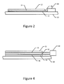
- the structure of an example embodiment also includes a light-curable adhesive 14 that is associated with at least one of the first structural component 10 or the second structural component 12.
- the light-curable adhesive may be impregnated within at least one of the first or second structural components or disposed between the first and second structural components.
- the light-curable adhesive may be disposed upon one or both of the facing surfaces of the first structural component or the doubler or patch so as to be positioned between the first structural component and the doubler or the patch once the doubler or the patch is bonded to the first structural component.
- the light-curable adhesive 14 is an ultraviolet-curable adhesive that cures in response to exposure to ultraviolet light.
- the ultraviolet-curable adhesive may be a Multi-Cure® 6-621 Series adhesive provided by Dymax® Corporation of Torrington, Connecticut.
- the light-curable adhesive 14 may be applied in various manners.
- the light-curable adhesive may be applied as a liquid or paste to one or both of the first and second structural components.
- the light-curable adhesive may be provided as a film, such as in sheet form.
- a sheet of light-curable adhesive may include a non-stick light-proof, e.g., ultraviolet-proof, backing on one or both of its opposed faces and be manufactured in rolls of variable width.
- a scrim cloth may be impregnated with a light-curable adhesive having a non-stick light-proof backing on one or both of its surfaces and manufactured as a roll of variable width.
- a film adhesive may also be referred to as a film adhesive.
- a scrim cloth is generally a relatively thin carrier, such as a carrier having a thickness of about 0.0005 inches and formed of fiberglass, spun polyester, e.g., remay, or the like.
- the bondline thickness may be further controlled and a solid film of light-curable adhesive may be more easily applied relative to the application of a liquid or paste adhesive.
- the structure of an example embodiment also includes one or more light guiding members 16 positioned between the first and second structural components 10, 12 and in communication, that is, optical communication, with the light-curable adhesive 14. As shown in Figures 1 and 2 , one or more light guiding members may be disposed upon or within the light-curable adhesive that is positioned between the first and second structural members. In accordance with an example embodiment of the present disclosure, the light guiding members are configured to emit light from side surfaces thereof along the length of the one or more light guiding members.
- the structure may include various types of light guiding members 16.
- the light guiding members may include one or more side-emitting optical fibers, such as a fiber optic mesh in which the optical fibers are side-emitting.
- the light guiding members may have various cross-sectional shapes, the side-emitting light guiding members of an example embodiment are cylindrical with a relatively small radius and a relatively long length.
- the side-emitting light guiding members of this example embodiment are circular in cross-section.
- the light guiding members may be formed of a variety of different types of materials, such as a plastic, a glass or various nanomaterials configured to guide light.
- the light-curable adhesive is an ultraviolet curable adhesive
- the light guiding members may be configured to guide ultraviolet light.
- the light-curable adhesive of other embodiments may be cured by light of other wavelengths, such as adhesives cured by white light or by the light emitted by light emitting diodes (LEDs), such that the light guiding members may correspondingly be configured to guide light of the other wavelengths.
- LEDs light emitting diodes
- the side-emitting light guiding members emit light along their length and not only at an end thereof. With respect to cylindrically-shaped side-emitting light guiding members, the light guiding members emit light through their side surface, such as by emitting light in every direction about the circumference of the light guiding members. By emitting light from the side surfaces of the light guiding members 16, a greater extent of the light-curable adhesive 14 may be exposed in a more uniform manner to the light emitted by the light guiding members than in instances in which light is only emitted from the end of an optical fiber.
- the adhesive that extends along the length of the light guiding member may be exposed to the light such that the adhesive is exposed to the light in a more uniform manner.
- the number and distribution of the light guiding members may be selected such that the adhesive is relatively uniformly exposed to light emitted by the light guiding members.
- a fiber optic mesh may serve as the light guiding members.
- the fiber optic mesh may include a plurality of side emitting optical fibers that extend in parallel across the adhesive and are spaced uniformly relative to one another.
- the fiber optic mesh may include a plurality of side-emitting optical fibers laterally spaced apart from one another.
- the fiber optic mesh may include one or more connectors 20, such as string or cords, that limit the separation between the optical fibers.
- the fiber optic mesh may have other configurations in other embodiments, such as configurations in which the optical fibers are disposed in a spiral configuration, are woven or the like.
- the side-emitting optical fibers of the fiber optic mesh of Figure 3 are shown to extend in parallel, the side-emitting optical fibers need not be parallel, but may extend in various different directions relative to one another in order to expose the adhesive to the light emitted from the side surfaces thereof, such as in a relatively uniform manner.
- a light source 18 may be communicably connected to the light guiding members 16 in order to introduce light into the light guiding members and to cause light to propagate therethrough.
- the light source may be optically coupled to one end of the light guiding members for injecting light in parallel through each of the light guiding members.
- the light then propagates along the length of the optical fiber and is emitted along the length of the optical fiber through the side surfaces so as to illuminate the light-curable adhesive 14 therealong.
- the light source may be an ultraviolet light source.
- the ends of the light guiding members opposite the light source may be formed by a reflective surface such that light reaching the opposed ends may be reflected and returned through the respective light guiding members.
- a second light source may be communicably coupled to the opposite ends of the light guiding members such that light is introduced through the opposed ends of the light guiding members.
- the light-curable adhesive 14 may be cured.
- the light-curable adhesive may be cured without otherwise heating the structure such the structure need not be placed in an autoclave.
- some pressure may be applied to the first and second structural components 10, 12 to urge the first and second structural components together, the structure need not be vacuum bagged, thereby further simplifying the curing process.
- the light-curable adhesive may be cured relatively quickly relative to at least some thermal adhesives, such as by being cured within 30 minutes or less, so as to further increase the efficiency of the curing process.
- the adhesive is cured upon a brief exposure to light, such as by being cured in less than 10 seconds, such as by being cured upon the exposure to light, such as light having a high intensity, for 2-4 seconds.
- the side-emitting light guiding members may be damaged by the transmission of the light, such as light having a high intensity, therethrough, but light sufficient to cure the adhesive may be emitted by the side-emitting light guiding members prior to being damaged.
- the structure may be comprised of other types of structural components.
- the structure may be comprised of a plurality of composite plies 32, as shown in Figure 4 .
- Each composite ply may include a plurality of fibers, such as graphite fibers, glass fibers or the like.
- the composite plies may be impregnated with the light-curable adhesive.
- the composite ply may be preimpregnated with the light-curable adhesive so as to be supplied in the form of a prepreg that includes both the fibers and the adhesive.
- the composite plies may be vacuum impregnated with the light-curable adhesive prior to layup.
- the ply may be subjected to resin infusion in which the resin is applied following the layup of the fibers.
- the one or more light guiding members 16 are positioned between each of the adjacent or neighboring composite plies 32, such as shown in Figure 4 .
- the light guiding members may be optically coupled to a light source 18 and may be configured to emit light from the side surfaces thereof such that the light-curable adhesive impregnated within the composite plies may be readily cured in a uniform manner.
- the fibers such as black carbon fibers, need not be transparent to light and, in one example embodiment, need not be transparent to ultraviolet light.
- composite materials utilizing transparent fibers may not have sufficient strength and toughness for all applications
- composite materials having opaque fibers, that is, fibers not transparent to light may include adhesive that is cured by the light emitted by side-emitting light guiding members in accordance with an example embodiment of the present disclosure.
- the fiber optic mesh may, instead, be inserted between some of the pairs of plies, but not all of the pairs of plies, such as in embodiments in which the plies include transparent fibers that facilitate the propagation of the light therethrough.
- light guiding members, such as a fiber optic mesh may be inserted between every second or every third ply.
- the spacing of the light guiding members may be governed by the distance through the plies that the light emitted by the side surfaces of the light guiding members will propagate with the light guiding members being spaced by a distance that still permits all of the adhesive in all of the plies, including those plies not immediately adjacent the light guiding members, to be exposed to light and cured.
- the adhesive is cured with light emitted by side surfaces of light guiding members disposed with the structure, the entire or a significant portion of the structure may be assembled prior to curing, thereby further increasing the efficiency by reducing the need for multiple cure cycles relative to other techniques that are limited to curing two or three plies at any one time.
- While two different types of structures have been described by way of example, a variety of other structures may be formed utilizing a light-curable adhesive 14 and one or more side-emitting light guiding members 16 for delivering the light to cure the light-curable adhesive.
- structures formed of composite materials in which the one or more light guiding members 16 are woven into the composite plies may be provided in accordance with an example embodiment of the present disclosure.
- a method is provided in accordance with an example embodiment in order to assemble a structure that is adhered by a light-curable adhesive 14.
- a light-curable adhesive such as an ultraviolet-curable adhesive
- the light-curable adhesive may be associated with the first and/or second structural components by impregnating at least one of the first or second structural components with the light-curable adhesive or by disposing the light-curable adhesive on at least one of the first or second structural components so as to be disposed between the first and second structural components.
- the light-curable adhesive may be disposed upon a first structural component so as to be sandwiched between the first and second structural components.
- the light-curable adhesive may be associated with the first and second structural components by impregnating a composite material that forms the first and second structural components with the light-curable adhesive.
- the method for assembling a structure may also associate one or more light guiding members 16, such as a plurality of side-emitting optical fibers, with at least one of the first structural component 10 or the second structural component 12.
- the one or more light guiding members may be disposed upon the first structural component.
- the one or more light guiding members may be configured to emit light from side surfaces thereof along the length of the one or more light guiding members.
- the method of this example embodiment may also include positioning a second structural component 12 upon the first structural component such that the first and second structural components are disposed in a facing relationship and the one or more light guiding members are in communication with the light-curable adhesive 14.
- the second structural component that is positioned upon the first structural component may be a composite ply, a doubler, a patch or the like.
- the positioning of the second structural component upon the first structural component causes the one or more light guiding members to thereafter be disposed between the first and second structural components.
- the structure may be provided that includes first and second structural components 10, 12 disposed in a facing relationship, the light-curable adhesive impregnated within at least one of the first and second structural components or disposed between the first and second structural components and one or more light guiding members 16 positioned between the first and second structural components.
- a light source 18 may be placed in communication with the one or more light guiding members, such as by being optically connected to one end of the light guiding members.
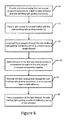
- light may be caused to propagate through the one or more side-emitting light guiding members and to be emitted from side surfaces along the length of the one or more light guiding members as shown in block 54 and by the uppermost optical fiber in Figure 3 .
- pressure may be applied to the first and second structural components to urge the first and second structural components together. See block 55 of Figure 6 .
- the light propagation through the side-emitting light guiding members is maintained until the light-curable adhesive is cured a result of the exposure of the light-curable adhesive to the light emitted from the side surfaces of the light guiding members.
- the propagation of the light through the one or more light guiding members may be ceased. See block 58.
- the one or more light guiding members remain within the structure following the curing of the light-curable adhesive, such as during the subsequent deployment of the structure.
- the structure may be formed or repaired in a more efficient manner, such as by reducing the need for elevated temperatures and pressures for substantial periods of time.
- the structure of an example embodiment may be formed without use of an autoclave and without vacuum bagging, thereby simplifying and streamlining the manufacturing or repair process.
- the second structural component comprises a doubler or a patch.
- the first and second structural components are comprised of composite material comprising fibers impregnated with the light-curable adhesive.
- the structure further comprises:
- the one or more light guiding members comprise a fiber optic mesh.
- light-curable adhesive comprises an ultraviolet curable adhesive.
- At least one of the first and second structural components comprises a composite material comprising a plurality of fibers that are not transparent to ultraviolet light.
- associating one or more side-emitting light guiding members with at least one of the first structural component or the second structural component comprises disposing the one or more side-emitting light guiding members upon the first structural component so as to be positioned between the first and second structural components following positioning of the second structural component upon the first structural component.
- positioning the second structural component upon the first structural component comprises positioning a doubler or a patch upon the first structural component.
- associating the light-curable adhesive with at least one of the first structural component or the second structural component comprises impregnating a composite material comprising fibers that comprises at least one of the first or second structural components with the light-curable adhesive.
- the method further comprises:
- associating the light-curable adhesive with at least one of the first structural component or the second structural component comprises associating an ultraviolet curable adhesive with at least one of the first structural component or the second structural component.
- At least one of the first and second structural components comprises a composite material comprising a plurality of fibers that are not transparent to ultraviolet light.
- the method further comprises placing a light source in communication with the one or more side-emitting light guiding members, wherein causing light to propagate through the one or more side-emitting light guiding members comprises providing light from the light source to the one or more side-emitting light guiding members for propagation therethrough.
- providing light from the light source comprises providing ultraviolet light from the light source, wherein the light-curable adhesive comprises an ultraviolet-curable adhesive.
- the method further comprises applying pressure to the first and second structural components to urge the first and second structural components together while causing light to propagate through one or more side-emitting light guiding members.
- maintaining the light propagation through the side-emitting light guiding members comprises maintaining the light propagation through the side-emitting light guiding members so as to cure the light-curable adhesive outside of an autoclave and without a vacuum bag.
- the method further comprises ceasing propagation of light through the one or more side-emitting light guiding members following curing of the light-curable adhesive, wherein the one or more side-emitting light guiding members remain within the structure following curing of the light-curable adhesive.
Landscapes
- Engineering & Computer Science (AREA)
- Mechanical Engineering (AREA)
- Physics & Mathematics (AREA)
- Health & Medical Sciences (AREA)
- Toxicology (AREA)
- Electromagnetism (AREA)
- Thermal Sciences (AREA)
- Oral & Maxillofacial Surgery (AREA)
- Chemical & Material Sciences (AREA)
- Chemical Kinetics & Catalysis (AREA)
- General Chemical & Material Sciences (AREA)
- Plasma & Fusion (AREA)
- Adhesives Or Adhesive Processes (AREA)
- Optical Couplings Of Light Guides (AREA)
- Optical Fibers, Optical Fiber Cores, And Optical Fiber Bundles (AREA)
- Lining Or Joining Of Plastics Or The Like (AREA)
- Light Guides In General And Applications Therefor (AREA)
Applications Claiming Priority (1)
| Application Number | Priority Date | Filing Date | Title |
|---|---|---|---|
| US14/508,551 US20160096353A1 (en) | 2014-10-07 | 2014-10-07 | Structure including a light-curable adhesive and associated method for assembling and curing same |
Publications (2)
| Publication Number | Publication Date |
|---|---|
| EP3009256A1 true EP3009256A1 (fr) | 2016-04-20 |
| EP3009256B1 EP3009256B1 (fr) | 2020-07-29 |
Family
ID=54145566
Family Applications (1)
| Application Number | Title | Priority Date | Filing Date |
|---|---|---|---|
| EP15183973.5A Active EP3009256B1 (fr) | 2014-10-07 | 2015-09-04 | Structure comprenant un adhésif durcissant à la lumière et procédé associé d'assemblage et de durcissement de celle-ci |
Country Status (6)
| Country | Link |
|---|---|
| US (1) | US20160096353A1 (fr) |
| EP (1) | EP3009256B1 (fr) |
| JP (1) | JP2016095495A (fr) |
| CN (1) | CN105479784A (fr) |
| AU (1) | AU2015210376B2 (fr) |
| CA (1) | CA2900631C (fr) |
Cited By (2)
| Publication number | Priority date | Publication date | Assignee | Title |
|---|---|---|---|---|
| DE102017122580A1 (de) * | 2017-09-28 | 2019-03-28 | Preh Gmbh | Verfahren zum Fügen zweier Fügepartner mittels strahlenhärtendem Material |
| US12180120B2 (en) | 2019-05-17 | 2024-12-31 | Rtx Corporation | Rapid processing of laminar composite components |
Families Citing this family (5)
| Publication number | Priority date | Publication date | Assignee | Title |
|---|---|---|---|---|
| DE102015212204A1 (de) * | 2015-06-30 | 2017-01-05 | Siemens Healthcare Gmbh | Medizinische Bildgebungsvorrichtung mit einer Beleuchtungseinheit |
| DE102015008312A1 (de) * | 2015-06-30 | 2017-01-05 | Airbus Defence and Space GmbH | Verfahren und Vorrichtung zum Reparieren von Bauteilen |
| US10274416B2 (en) * | 2017-05-18 | 2019-04-30 | The Boeing Company | Peel adhesion test specimens and method for their preparation |
| US10833774B2 (en) * | 2019-01-02 | 2020-11-10 | The Boeing Company | Embedded fiber optic sensor system |
| DE102019130566A1 (de) * | 2019-11-13 | 2021-05-20 | HELLA GmbH & Co. KGaA | Fügeanordnung und Verfahren zum Fügen von Bauteilen und Lichtleitelement zur Verwendung darin |
Citations (3)
| Publication number | Priority date | Publication date | Assignee | Title |
|---|---|---|---|---|
| DE19604081A1 (de) * | 1996-02-05 | 1997-08-07 | Inpro Innovations Gmbh | Verfahren zum Verbinden von Bauteilen, insbesondere von Kfz-Karosserieteilen, mittels eines Klebers oder eines Lots |
| WO1998025065A1 (fr) * | 1996-12-07 | 1998-06-11 | Central Research Laboratories Limited | Raccord pour fluides |
| US20050136210A1 (en) * | 2003-12-22 | 2005-06-23 | 3M Innovative Properties Company | Method of curing using an electroluminescent light |
Family Cites Families (15)
| Publication number | Priority date | Publication date | Assignee | Title |
|---|---|---|---|---|
| US5524679A (en) * | 1991-03-19 | 1996-06-11 | Page Automated Telecommunications Systems, Inc. | Smart skin array woven fiber optic ribbon and arrays and packaging thereof |
| US5166007A (en) * | 1991-09-11 | 1992-11-24 | Smith W Novis | Repair compositions and structure |
| IT1316598B1 (it) * | 2000-08-07 | 2003-04-24 | Caen Microelettronica E Sistem | Manufatto tessile con fibre illuminate, capo di abbigliamento daquesto ottenuto e metodo di produzione del manufatto. |
| US6835679B2 (en) * | 2001-12-27 | 2004-12-28 | Continuum Dynamics, Inc. | Lossy fiber UV curing method and apparatus |
| JP3924603B2 (ja) * | 2004-07-28 | 2007-06-06 | 福井県 | 光ファイバ及びそれを備えた布帛並びにその加工方法及び装置 |
| GB2423279B (en) * | 2005-02-18 | 2010-08-18 | Uvasol Ltd | Changing the state of a body of material |
| JP2007169807A (ja) * | 2005-12-20 | 2007-07-05 | Mitsubishi Rayon Co Ltd | 光ファイバ織物、リード付光ファイバ織物、及びそれらの製造方法 |
| GB0711120D0 (en) * | 2007-06-09 | 2007-07-18 | Rolls Royce Plc | Polymer components |
| JP2010095633A (ja) * | 2008-10-16 | 2010-04-30 | Omron Corp | 接着方法、接着構造、光学モジュールの製造方法および光学モジュール |
| TWM374579U (en) * | 2009-06-24 | 2010-02-21 | Li-Zhen Wang | Lateral optical fiber structure |
| KR101367253B1 (ko) * | 2010-10-13 | 2014-03-13 | 제일모직 주식회사 | 감광성 수지 조성물 및 이를 이용한 차광층 |
| US8492448B2 (en) * | 2011-10-07 | 2013-07-23 | Corning Incorporated | Systems and methods for performing photoreactions using light-diffusing optical fiber |
| CN202805773U (zh) * | 2012-04-13 | 2013-03-20 | 上海科斗电子科技有限公司 | 高强度光固化产品 |
| US9724893B2 (en) * | 2013-02-04 | 2017-08-08 | The Florida International University Board Of Trustees | Out-of-autoclave curing system |
| US9242429B2 (en) * | 2013-03-14 | 2016-01-26 | Apple Inc. | Activated thread curing of liquid adhesives |
-
2014
- 2014-10-07 US US14/508,551 patent/US20160096353A1/en not_active Abandoned
-
2015
- 2015-08-05 AU AU2015210376A patent/AU2015210376B2/en active Active
- 2015-08-14 CA CA2900631A patent/CA2900631C/fr active Active
- 2015-08-27 CN CN201510533092.4A patent/CN105479784A/zh active Pending
- 2015-09-04 EP EP15183973.5A patent/EP3009256B1/fr active Active
- 2015-09-28 JP JP2015189337A patent/JP2016095495A/ja active Pending
Patent Citations (3)
| Publication number | Priority date | Publication date | Assignee | Title |
|---|---|---|---|---|
| DE19604081A1 (de) * | 1996-02-05 | 1997-08-07 | Inpro Innovations Gmbh | Verfahren zum Verbinden von Bauteilen, insbesondere von Kfz-Karosserieteilen, mittels eines Klebers oder eines Lots |
| WO1998025065A1 (fr) * | 1996-12-07 | 1998-06-11 | Central Research Laboratories Limited | Raccord pour fluides |
| US20050136210A1 (en) * | 2003-12-22 | 2005-06-23 | 3M Innovative Properties Company | Method of curing using an electroluminescent light |
Cited By (4)
| Publication number | Priority date | Publication date | Assignee | Title |
|---|---|---|---|---|
| DE102017122580A1 (de) * | 2017-09-28 | 2019-03-28 | Preh Gmbh | Verfahren zum Fügen zweier Fügepartner mittels strahlenhärtendem Material |
| DE102017122580B4 (de) | 2017-09-28 | 2021-11-25 | Preh Gmbh | Verfahren zum Fügen zweier Fügepartner mittels strahlenhärtendem Material und Anordnung zur Durchführung eines Fügeverfahrens |
| US12180120B2 (en) | 2019-05-17 | 2024-12-31 | Rtx Corporation | Rapid processing of laminar composite components |
| EP3738768B1 (fr) * | 2019-05-17 | 2026-04-08 | RTX Corporation | Traitement rapide de composants composites laminaires |
Also Published As
| Publication number | Publication date |
|---|---|
| CN105479784A (zh) | 2016-04-13 |
| CA2900631A1 (fr) | 2016-04-07 |
| AU2015210376A1 (en) | 2016-04-21 |
| CA2900631C (fr) | 2017-10-17 |
| JP2016095495A (ja) | 2016-05-26 |
| US20160096353A1 (en) | 2016-04-07 |
| AU2015210376B2 (en) | 2020-05-21 |
| EP3009256B1 (fr) | 2020-07-29 |
Similar Documents
| Publication | Publication Date | Title |
|---|---|---|
| CA2900631C (fr) | Structure comportant un adhesif durcissable a la lumiere et methode associee d'assemblage et de durcissement de ladite structure | |
| US6739861B2 (en) | High pressure co-cure of lightweight core composite article utilizing a core having a plurality of protruding pins | |
| AU2015200414B2 (en) | Fabrication of composite laminates using temporarily stitched preforms | |
| EP1311768B1 (fr) | Dispositif et procede servant a joindre des materiaux dissemblables afin de constituer un element de support structural | |
| US8834668B2 (en) | Staged cocuring of composite structures | |
| US20110127698A1 (en) | Vacuum bag for hot drape forming | |
| US9186756B2 (en) | Repair method and repair structure for honeycomb sandwich structural body | |
| US8257537B2 (en) | Manufacturing device and manufacturing method of laminate | |
| US8262823B2 (en) | Window skin panel and method of making same | |
| US9724893B2 (en) | Out-of-autoclave curing system | |
| JP2010137527A (ja) | 複合材料の修理方法 | |
| EP2853380B1 (fr) | Textiles composites comprenant des filaments étalés | |
| US11045980B2 (en) | Method for molding composite materials | |
| US5604836A (en) | Optical fiber entry strain relief interface for compression-molded structures | |
| CN106640872A (zh) | 一种连接带紧固构件 | |
| EP3112118A1 (fr) | Procédé et appareil de production d'un composant par utilisation d'un film sous vide | |
| JP2020508238A (ja) | 複合製品 |
Legal Events
| Date | Code | Title | Description |
|---|---|---|---|
| PUAI | Public reference made under article 153(3) epc to a published international application that has entered the european phase |
Free format text: ORIGINAL CODE: 0009012 |
|
| 17P | Request for examination filed |
Effective date: 20150904 |
|
| AK | Designated contracting states |
Kind code of ref document: A1 Designated state(s): AL AT BE BG CH CY CZ DE DK EE ES FI FR GB GR HR HU IE IS IT LI LT LU LV MC MK MT NL NO PL PT RO RS SE SI SK SM TR |
|
| AX | Request for extension of the european patent |
Extension state: BA ME |
|
| STAA | Information on the status of an ep patent application or granted ep patent |
Free format text: STATUS: EXAMINATION IS IN PROGRESS |
|
| 17Q | First examination report despatched |
Effective date: 20190301 |
|
| GRAP | Despatch of communication of intention to grant a patent |
Free format text: ORIGINAL CODE: EPIDOSNIGR1 |
|
| STAA | Information on the status of an ep patent application or granted ep patent |
Free format text: STATUS: GRANT OF PATENT IS INTENDED |
|
| INTG | Intention to grant announced |
Effective date: 20200221 |
|
| GRAS | Grant fee paid |
Free format text: ORIGINAL CODE: EPIDOSNIGR3 |
|
| GRAJ | Information related to disapproval of communication of intention to grant by the applicant or resumption of examination proceedings by the epo deleted |
Free format text: ORIGINAL CODE: EPIDOSDIGR1 |
|
| GRAL | Information related to payment of fee for publishing/printing deleted |
Free format text: ORIGINAL CODE: EPIDOSDIGR3 |
|
| STAA | Information on the status of an ep patent application or granted ep patent |
Free format text: STATUS: EXAMINATION IS IN PROGRESS |
|
| GRAR | Information related to intention to grant a patent recorded |
Free format text: ORIGINAL CODE: EPIDOSNIGR71 |
|
| STAA | Information on the status of an ep patent application or granted ep patent |
Free format text: STATUS: GRANT OF PATENT IS INTENDED |
|
| GRAA | (expected) grant |
Free format text: ORIGINAL CODE: 0009210 |
|
| STAA | Information on the status of an ep patent application or granted ep patent |
Free format text: STATUS: THE PATENT HAS BEEN GRANTED |
|
| INTC | Intention to grant announced (deleted) | ||
| AK | Designated contracting states |
Kind code of ref document: B1 Designated state(s): AL AT BE BG CH CY CZ DE DK EE ES FI FR GB GR HR HU IE IS IT LI LT LU LV MC MK MT NL NO PL PT RO RS SE SI SK SM TR |
|
| INTG | Intention to grant announced |
Effective date: 20200622 |
|
| REG | Reference to a national code |
Ref country code: CH Ref legal event code: EP |
|
| REG | Reference to a national code |
Ref country code: AT Ref legal event code: REF Ref document number: 1295293 Country of ref document: AT Kind code of ref document: T Effective date: 20200815 |
|
| REG | Reference to a national code |
Ref country code: IE Ref legal event code: FG4D |
|
| REG | Reference to a national code |
Ref country code: DE Ref legal event code: R096 Ref document number: 602015056423 Country of ref document: DE |
|
| REG | Reference to a national code |
Ref country code: LT Ref legal event code: MG4D |
|
| REG | Reference to a national code |
Ref country code: NL Ref legal event code: MP Effective date: 20200729 |
|
| REG | Reference to a national code |
Ref country code: AT Ref legal event code: MK05 Ref document number: 1295293 Country of ref document: AT Kind code of ref document: T Effective date: 20200729 |
|
| PG25 | Lapsed in a contracting state [announced via postgrant information from national office to epo] |
Ref country code: GR Free format text: LAPSE BECAUSE OF FAILURE TO SUBMIT A TRANSLATION OF THE DESCRIPTION OR TO PAY THE FEE WITHIN THE PRESCRIBED TIME-LIMIT Effective date: 20201030 Ref country code: LT Free format text: LAPSE BECAUSE OF FAILURE TO SUBMIT A TRANSLATION OF THE DESCRIPTION OR TO PAY THE FEE WITHIN THE PRESCRIBED TIME-LIMIT Effective date: 20200729 Ref country code: FI Free format text: LAPSE BECAUSE OF FAILURE TO SUBMIT A TRANSLATION OF THE DESCRIPTION OR TO PAY THE FEE WITHIN THE PRESCRIBED TIME-LIMIT Effective date: 20200729 Ref country code: BG Free format text: LAPSE BECAUSE OF FAILURE TO SUBMIT A TRANSLATION OF THE DESCRIPTION OR TO PAY THE FEE WITHIN THE PRESCRIBED TIME-LIMIT Effective date: 20201029 Ref country code: NO Free format text: LAPSE BECAUSE OF FAILURE TO SUBMIT A TRANSLATION OF THE DESCRIPTION OR TO PAY THE FEE WITHIN THE PRESCRIBED TIME-LIMIT Effective date: 20201029 Ref country code: AT Free format text: LAPSE BECAUSE OF FAILURE TO SUBMIT A TRANSLATION OF THE DESCRIPTION OR TO PAY THE FEE WITHIN THE PRESCRIBED TIME-LIMIT Effective date: 20200729 Ref country code: ES Free format text: LAPSE BECAUSE OF FAILURE TO SUBMIT A TRANSLATION OF THE DESCRIPTION OR TO PAY THE FEE WITHIN THE PRESCRIBED TIME-LIMIT Effective date: 20200729 Ref country code: SE Free format text: LAPSE BECAUSE OF FAILURE TO SUBMIT A TRANSLATION OF THE DESCRIPTION OR TO PAY THE FEE WITHIN THE PRESCRIBED TIME-LIMIT Effective date: 20200729 Ref country code: PT Free format text: LAPSE BECAUSE OF FAILURE TO SUBMIT A TRANSLATION OF THE DESCRIPTION OR TO PAY THE FEE WITHIN THE PRESCRIBED TIME-LIMIT Effective date: 20201130 Ref country code: HR Free format text: LAPSE BECAUSE OF FAILURE TO SUBMIT A TRANSLATION OF THE DESCRIPTION OR TO PAY THE FEE WITHIN THE PRESCRIBED TIME-LIMIT Effective date: 20200729 |
|
| PG25 | Lapsed in a contracting state [announced via postgrant information from national office to epo] |
Ref country code: PL Free format text: LAPSE BECAUSE OF FAILURE TO SUBMIT A TRANSLATION OF THE DESCRIPTION OR TO PAY THE FEE WITHIN THE PRESCRIBED TIME-LIMIT Effective date: 20200729 Ref country code: RS Free format text: LAPSE BECAUSE OF FAILURE TO SUBMIT A TRANSLATION OF THE DESCRIPTION OR TO PAY THE FEE WITHIN THE PRESCRIBED TIME-LIMIT Effective date: 20200729 Ref country code: LV Free format text: LAPSE BECAUSE OF FAILURE TO SUBMIT A TRANSLATION OF THE DESCRIPTION OR TO PAY THE FEE WITHIN THE PRESCRIBED TIME-LIMIT Effective date: 20200729 Ref country code: IS Free format text: LAPSE BECAUSE OF FAILURE TO SUBMIT A TRANSLATION OF THE DESCRIPTION OR TO PAY THE FEE WITHIN THE PRESCRIBED TIME-LIMIT Effective date: 20201129 |
|
| PG25 | Lapsed in a contracting state [announced via postgrant information from national office to epo] |
Ref country code: NL Free format text: LAPSE BECAUSE OF FAILURE TO SUBMIT A TRANSLATION OF THE DESCRIPTION OR TO PAY THE FEE WITHIN THE PRESCRIBED TIME-LIMIT Effective date: 20200729 |
|
| PG25 | Lapsed in a contracting state [announced via postgrant information from national office to epo] |
Ref country code: MC Free format text: LAPSE BECAUSE OF FAILURE TO SUBMIT A TRANSLATION OF THE DESCRIPTION OR TO PAY THE FEE WITHIN THE PRESCRIBED TIME-LIMIT Effective date: 20200729 Ref country code: RO Free format text: LAPSE BECAUSE OF FAILURE TO SUBMIT A TRANSLATION OF THE DESCRIPTION OR TO PAY THE FEE WITHIN THE PRESCRIBED TIME-LIMIT Effective date: 20200729 Ref country code: SM Free format text: LAPSE BECAUSE OF FAILURE TO SUBMIT A TRANSLATION OF THE DESCRIPTION OR TO PAY THE FEE WITHIN THE PRESCRIBED TIME-LIMIT Effective date: 20200729 Ref country code: EE Free format text: LAPSE BECAUSE OF FAILURE TO SUBMIT A TRANSLATION OF THE DESCRIPTION OR TO PAY THE FEE WITHIN THE PRESCRIBED TIME-LIMIT Effective date: 20200729 Ref country code: IT Free format text: LAPSE BECAUSE OF FAILURE TO SUBMIT A TRANSLATION OF THE DESCRIPTION OR TO PAY THE FEE WITHIN THE PRESCRIBED TIME-LIMIT Effective date: 20200729 Ref country code: CZ Free format text: LAPSE BECAUSE OF FAILURE TO SUBMIT A TRANSLATION OF THE DESCRIPTION OR TO PAY THE FEE WITHIN THE PRESCRIBED TIME-LIMIT Effective date: 20200729 Ref country code: DK Free format text: LAPSE BECAUSE OF FAILURE TO SUBMIT A TRANSLATION OF THE DESCRIPTION OR TO PAY THE FEE WITHIN THE PRESCRIBED TIME-LIMIT Effective date: 20200729 |
|
| REG | Reference to a national code |
Ref country code: CH Ref legal event code: PL Ref country code: DE Ref legal event code: R097 Ref document number: 602015056423 Country of ref document: DE |
|
| PG25 | Lapsed in a contracting state [announced via postgrant information from national office to epo] |
Ref country code: AL Free format text: LAPSE BECAUSE OF FAILURE TO SUBMIT A TRANSLATION OF THE DESCRIPTION OR TO PAY THE FEE WITHIN THE PRESCRIBED TIME-LIMIT Effective date: 20200729 |
|
| PLBE | No opposition filed within time limit |
Free format text: ORIGINAL CODE: 0009261 |
|
| STAA | Information on the status of an ep patent application or granted ep patent |
Free format text: STATUS: NO OPPOSITION FILED WITHIN TIME LIMIT |
|
| REG | Reference to a national code |
Ref country code: BE Ref legal event code: MM Effective date: 20200930 |
|
| PG25 | Lapsed in a contracting state [announced via postgrant information from national office to epo] |
Ref country code: LU Free format text: LAPSE BECAUSE OF NON-PAYMENT OF DUE FEES Effective date: 20200904 Ref country code: SK Free format text: LAPSE BECAUSE OF FAILURE TO SUBMIT A TRANSLATION OF THE DESCRIPTION OR TO PAY THE FEE WITHIN THE PRESCRIBED TIME-LIMIT Effective date: 20200729 |
|
| 26N | No opposition filed |
Effective date: 20210430 |
|
| PG25 | Lapsed in a contracting state [announced via postgrant information from national office to epo] |
Ref country code: BE Free format text: LAPSE BECAUSE OF NON-PAYMENT OF DUE FEES Effective date: 20200930 Ref country code: CH Free format text: LAPSE BECAUSE OF NON-PAYMENT OF DUE FEES Effective date: 20200930 Ref country code: IE Free format text: LAPSE BECAUSE OF NON-PAYMENT OF DUE FEES Effective date: 20200904 Ref country code: LI Free format text: LAPSE BECAUSE OF NON-PAYMENT OF DUE FEES Effective date: 20200930 Ref country code: SI Free format text: LAPSE BECAUSE OF FAILURE TO SUBMIT A TRANSLATION OF THE DESCRIPTION OR TO PAY THE FEE WITHIN THE PRESCRIBED TIME-LIMIT Effective date: 20200729 |
|
| PG25 | Lapsed in a contracting state [announced via postgrant information from national office to epo] |
Ref country code: TR Free format text: LAPSE BECAUSE OF FAILURE TO SUBMIT A TRANSLATION OF THE DESCRIPTION OR TO PAY THE FEE WITHIN THE PRESCRIBED TIME-LIMIT Effective date: 20200729 Ref country code: MT Free format text: LAPSE BECAUSE OF FAILURE TO SUBMIT A TRANSLATION OF THE DESCRIPTION OR TO PAY THE FEE WITHIN THE PRESCRIBED TIME-LIMIT Effective date: 20200729 Ref country code: CY Free format text: LAPSE BECAUSE OF FAILURE TO SUBMIT A TRANSLATION OF THE DESCRIPTION OR TO PAY THE FEE WITHIN THE PRESCRIBED TIME-LIMIT Effective date: 20200729 |
|
| PG25 | Lapsed in a contracting state [announced via postgrant information from national office to epo] |
Ref country code: MK Free format text: LAPSE BECAUSE OF FAILURE TO SUBMIT A TRANSLATION OF THE DESCRIPTION OR TO PAY THE FEE WITHIN THE PRESCRIBED TIME-LIMIT Effective date: 20200729 |
|
| P01 | Opt-out of the competence of the unified patent court (upc) registered |
Effective date: 20230516 |
|
| PGFP | Annual fee paid to national office [announced via postgrant information from national office to epo] |
Ref country code: DE Payment date: 20250929 Year of fee payment: 11 |
|
| PGFP | Annual fee paid to national office [announced via postgrant information from national office to epo] |
Ref country code: GB Payment date: 20250929 Year of fee payment: 11 |
|
| PGFP | Annual fee paid to national office [announced via postgrant information from national office to epo] |
Ref country code: FR Payment date: 20250925 Year of fee payment: 11 |