EP3009291B1 - Appareil de bouchon de réservoir de carburant à utiliser avec des circuits de mise à l'air libre carburant - Google Patents
Appareil de bouchon de réservoir de carburant à utiliser avec des circuits de mise à l'air libre carburant Download PDFInfo
- Publication number
- EP3009291B1 EP3009291B1 EP15003054.2A EP15003054A EP3009291B1 EP 3009291 B1 EP3009291 B1 EP 3009291B1 EP 15003054 A EP15003054 A EP 15003054A EP 3009291 B1 EP3009291 B1 EP 3009291B1
- Authority
- EP
- European Patent Office
- Prior art keywords
- fuel
- fuel cap
- membrane
- cap apparatus
- openings
- Prior art date
- Legal status (The legal status is an assumption and is not a legal conclusion. Google has not performed a legal analysis and makes no representation as to the accuracy of the status listed.)
- Active
Links
Images


Classifications
-
- B—PERFORMING OPERATIONS; TRANSPORTING
- B60—VEHICLES IN GENERAL
- B60K—ARRANGEMENT OR MOUNTING OF PROPULSION UNITS OR OF TRANSMISSIONS IN VEHICLES; ARRANGEMENT OR MOUNTING OF PLURAL DIVERSE PRIME-MOVERS IN VEHICLES; AUXILIARY DRIVES FOR VEHICLES; INSTRUMENTATION OR DASHBOARDS FOR VEHICLES; ARRANGEMENTS IN CONNECTION WITH COOLING, AIR INTAKE, GAS EXHAUST OR FUEL SUPPLY OF PROPULSION UNITS IN VEHICLES
- B60K15/00—Arrangement in connection with fuel supply of combustion engines or other fuel consuming energy converters, e.g. fuel cells; Mounting or construction of fuel tanks
- B60K15/03—Fuel tanks
- B60K15/04—Tank inlets
- B60K15/0406—Filler caps for fuel tanks
-
- B—PERFORMING OPERATIONS; TRANSPORTING
- B60—VEHICLES IN GENERAL
- B60K—ARRANGEMENT OR MOUNTING OF PROPULSION UNITS OR OF TRANSMISSIONS IN VEHICLES; ARRANGEMENT OR MOUNTING OF PLURAL DIVERSE PRIME-MOVERS IN VEHICLES; AUXILIARY DRIVES FOR VEHICLES; INSTRUMENTATION OR DASHBOARDS FOR VEHICLES; ARRANGEMENTS IN CONNECTION WITH COOLING, AIR INTAKE, GAS EXHAUST OR FUEL SUPPLY OF PROPULSION UNITS IN VEHICLES
- B60K15/00—Arrangement in connection with fuel supply of combustion engines or other fuel consuming energy converters, e.g. fuel cells; Mounting or construction of fuel tanks
- B60K15/03—Fuel tanks
- B60K15/035—Fuel tanks characterised by venting means
-
- B—PERFORMING OPERATIONS; TRANSPORTING
- B60—VEHICLES IN GENERAL
- B60K—ARRANGEMENT OR MOUNTING OF PROPULSION UNITS OR OF TRANSMISSIONS IN VEHICLES; ARRANGEMENT OR MOUNTING OF PLURAL DIVERSE PRIME-MOVERS IN VEHICLES; AUXILIARY DRIVES FOR VEHICLES; INSTRUMENTATION OR DASHBOARDS FOR VEHICLES; ARRANGEMENTS IN CONNECTION WITH COOLING, AIR INTAKE, GAS EXHAUST OR FUEL SUPPLY OF PROPULSION UNITS IN VEHICLES
- B60K15/00—Arrangement in connection with fuel supply of combustion engines or other fuel consuming energy converters, e.g. fuel cells; Mounting or construction of fuel tanks
- B60K15/03—Fuel tanks
- B60K15/035—Fuel tanks characterised by venting means
- B60K15/03504—Fuel tanks characterised by venting means adapted to avoid loss of fuel or fuel vapour, e.g. with vapour recovery systems
-
- B—PERFORMING OPERATIONS; TRANSPORTING
- B60—VEHICLES IN GENERAL
- B60K—ARRANGEMENT OR MOUNTING OF PROPULSION UNITS OR OF TRANSMISSIONS IN VEHICLES; ARRANGEMENT OR MOUNTING OF PLURAL DIVERSE PRIME-MOVERS IN VEHICLES; AUXILIARY DRIVES FOR VEHICLES; INSTRUMENTATION OR DASHBOARDS FOR VEHICLES; ARRANGEMENTS IN CONNECTION WITH COOLING, AIR INTAKE, GAS EXHAUST OR FUEL SUPPLY OF PROPULSION UNITS IN VEHICLES
- B60K15/00—Arrangement in connection with fuel supply of combustion engines or other fuel consuming energy converters, e.g. fuel cells; Mounting or construction of fuel tanks
- B60K15/03—Fuel tanks
- B60K15/035—Fuel tanks characterised by venting means
- B60K15/03504—Fuel tanks characterised by venting means adapted to avoid loss of fuel or fuel vapour, e.g. with vapour recovery systems
- B60K2015/03509—Fuel tanks characterised by venting means adapted to avoid loss of fuel or fuel vapour, e.g. with vapour recovery systems with a droplet separator in the vent line
-
- B—PERFORMING OPERATIONS; TRANSPORTING
- B60—VEHICLES IN GENERAL
- B60K—ARRANGEMENT OR MOUNTING OF PROPULSION UNITS OR OF TRANSMISSIONS IN VEHICLES; ARRANGEMENT OR MOUNTING OF PLURAL DIVERSE PRIME-MOVERS IN VEHICLES; AUXILIARY DRIVES FOR VEHICLES; INSTRUMENTATION OR DASHBOARDS FOR VEHICLES; ARRANGEMENTS IN CONNECTION WITH COOLING, AIR INTAKE, GAS EXHAUST OR FUEL SUPPLY OF PROPULSION UNITS IN VEHICLES
- B60K15/00—Arrangement in connection with fuel supply of combustion engines or other fuel consuming energy converters, e.g. fuel cells; Mounting or construction of fuel tanks
- B60K15/03—Fuel tanks
- B60K15/035—Fuel tanks characterised by venting means
- B60K2015/03542—Mounting of the venting means
- B60K2015/03547—Mounting of the venting means the venting means are integrated in the fuel cap or inlet cover
-
- B—PERFORMING OPERATIONS; TRANSPORTING
- B60—VEHICLES IN GENERAL
- B60K—ARRANGEMENT OR MOUNTING OF PROPULSION UNITS OR OF TRANSMISSIONS IN VEHICLES; ARRANGEMENT OR MOUNTING OF PLURAL DIVERSE PRIME-MOVERS IN VEHICLES; AUXILIARY DRIVES FOR VEHICLES; INSTRUMENTATION OR DASHBOARDS FOR VEHICLES; ARRANGEMENTS IN CONNECTION WITH COOLING, AIR INTAKE, GAS EXHAUST OR FUEL SUPPLY OF PROPULSION UNITS IN VEHICLES
- B60K15/00—Arrangement in connection with fuel supply of combustion engines or other fuel consuming energy converters, e.g. fuel cells; Mounting or construction of fuel tanks
- B60K15/03—Fuel tanks
- B60K15/04—Tank inlets
- B60K15/0406—Filler caps for fuel tanks
- B60K2015/0451—Sealing means in the closure cap
Definitions
- the present disclosure relates generally to fuel caps and, more particularly, to fuel cap apparatus for use with fuel venting systems.
- venting a fuel tank equalizes the pressure in the tank by releasing fuel vapors and allowing atmospheric air to flow into the fuel tank so that the liquid fuel can be drawn from the tank via suction.
- Some venting systems employ a separate venting tube or line to vent the fuel tank, while other venting systems employ a venting tube in combination with a filling device.
- a separate vent tube prevents the buildup of fuel pressure within the tank, it does not prevent contamination of the environment as a result of unintentional overboard venting of liquid fuel, which frequently occurs when a marine fuel tank is being refueled due to fuel tank overfilling and/or due to splashing, sloshing or other fuel surges during boat movement.
- separate vent tubes are prone to allow the ingress of water and other contaminates into the fuel stored in the tank, which can lead to engine damage.
- vent tube and filling device are often combined and in fluid communication.
- boats are provided with a filling device integrally formed with a vent tube that can mount to a deck of the boat and connect to the fuel tank via fluid hoses and/or other conduits.
- the combined filling device and vent tube prevents the unintentional overboard venting of liquid fuel during boat movements and returns fuel overflow to the tank in case of tank overfill.
- a combined vent tube and filling device typically requires a fuel cap that has a vent formed therein.
- a vented fuel cap must typically allow adequate airflow through the fuel cap and prevent water and other contaminates from passing through the vent of the fuel cap and into the fuel tank.
- Preventing the ingress of water through the fuel cap is important to prevent engine damage.
- allowing the venting of fuel vapors is also important to release the fuel vapors from the fuel tank and allow sufficient atmospheric airflow so that the liquid fuel in the tank can flow to the engine.
- a vented fuel cap typically requires a passageway in which the venting area is large enough to allow vapors and atmospheric air to pass therethrough, but small enough to prevent the ingress of water and other contaminates.
- a passageway that is small enough to prevent the ingress of water and other contaminates often provides an insufficient and ineffective venting area for venting atmospheric air and fuel vapors.
- US 3 909 302 A discloses a vent cap for a liquid acid electrolyte storage cell, comprising a membrane, which is permeable to oxygen and hydrogen gas and substantially impermeable to the liquid electrolyte.
- the membrane is clamped to the vent cap body by means of a stiff, yet flexible member, which acts as a protective cover for the membrane and secures the membrane by a pure mechanical action, thereby avoiding the problems attendant to bonding.
- the advantage of the vent cap is to provide a membrane that is replaceable and accessible for maintenance.
- US 4 136 796 A relates discloses an improved closure for containers or drums which permit the venting of gasses therein, while at the same time, preventing passage therethrough of liquids or other materials stored therein.
- the removable and replaceable plug bears a membrane selective in its ability to pass gasses but not liquids.
- EP 1 202 616 A1 discloses a protective venting element for electronic housings.
- the plastic body has a microporous, waterproof and gas-permeable membrane and a metalized surface, formed by a layer of electrically conductive material. There is a high gas permeability of the membrane for venting of the electronic housing.
- GB 2 376 460 A discloses a fuel filler cap comprising a body, a pressure relief valve to control the flow of air through the aperture, and a cover. Projections are provided on the body and the cover which co-operate to define a labyrinthine path between the atmosphere and the valve, so that any dirt carried by indrawn air is trapped before entering the fuel tank.
- the example fuel cap apparatus described herein provides a vented fuel cap for use with fuel fill apparatus such as, for example, a fuel fill apparatus of a marine craft (e.g., a boat).
- fuel fill apparatus such as, for example, a fuel fill apparatus of a marine craft (e.g., a boat).
- the example apparatus described herein provides a fuel cap having a vent passageway that inhibits water and other contaminates from entering through the fuel cap while having a venting area that allows sufficient and effective continuous fuel tank ventilation. Additionally, the example fuel cap prevents liquid fluid (e.g., fuel) from escaping through the vent passageway of the fuel cap.
- the example fuel cap apparatus includes a membrane coated with a material (e.g., a hydrophobic material) that repels liquid to prevent ingress of water through the membrane.
- the material can be a fluoropolymer material (commonly known as Teflon®) such as, for example, polytetrafluoroethylene, etc.
- Teflon® fluoropolymer material
- the membrane may be integrally formed with the fuel cap to form one or more venting passageways that substantially inhibit the ingress of water and other contaminants into a fuel tank and allow the ingress of atmospheric air and the egress of fuel vapors through the one or more passageways at relatively high flow rates.
- the example fuel cap apparatus includes a deflection shield that creates a treacherous path to substantially prevent liquid fuel from flowing through the passageways (e.g., from the fuel tank) and into the environment.
- FIG. 1A illustrates an example fuel filling assembly or fuel fill apparatus 100 for use with marine crafts that is implemented with an example closure cap assembly 102 described herein.
- the example fuel fill apparatus 100 may be referred to as a deckfill and is adapted for mounting to a deck of a marine craft such as, for example, a deck 302 ( FIG. 3 ) of a boat (not shown).
- the example fuel fill apparatus 100 includes a fill tube 104 and a vent tube 106 that extends through an opening 304 ( FIG. 3 ) of the deck 302 when the fuel fill apparatus 100 is mounted to the deck 302 of a boat.
- fluid hoses and/or other conduits are coupled to terminal ends 108 and 110 of the fill tube 104 and the vent tube 106, respectively, and extend to the fuel tank, which is typically positioned below the deck 302.
- the fill tube 104 and/or the vent tube 106 can be angled or slanted to facilitate the positioning and installation of the fuel fill apparatus 100 to the boat and/or the fluid hoses or other conduits and reduce the possibility of fuel spillage when filling the fuel tank.
- the fill tube 104 and the vent tube 106 may be substantially straight.
- the fuel fill apparatus 100 of FIGS. 1A and 1B can be made of resinous or metal alloy materials such as polypropylene, nylon, stainless steel, bronze, aluminum, and/or any other suitable materials that are resistant to impact, fuel, weather, etc.
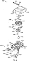
- FIG. 1B illustrates an exploded view of the example fuel fill devices or apparatus 100 of FIG. 1A .
- the fill tube 104 typically includes a generally planar, base plate or flange 112 that supports the fill tube 104 and the vent tube 106 when the fuel fill apparatus 100 is mounted to the deck 302 ( FIG. 3 ).
- the flange 112 is illustrated as a circular flange that engages a surface 306 ( FIG. 3 ) of the boat deck 302 and has a plurality of mounting holes 114 for mounting the fuel fill device 100 to the surface 306 of the deck 302.
- the fuel fill apparatus 100 can be mounted to the deck 302 of the boat via screws or any other suitable fastening mechanism(s) that pass into and/or through the mounting holes 114.
- the fill tube 104, the vent tube 106, and the flange 112 are integrally formed (e.g., via injection molding) as a substantially unitary piece or structure.
- the fill tube 104, the vent tube 106, and the flange 112 can be separate components coupled together via fasteners or any other suitable fastening mechanism(s).
- the flange 112 can be square or any other polygonal-shaped member.
- the fill tube 104 has an opening 116 for receiving a nozzle such as, for example, a nozzle of a fuel pump, etc.
- the closure cap assembly 102 removably couples to the opening 116. When coupled to the opening 116, the closure cap assembly 102 sealingly engages the opening 116 to close the opening 116 of the fill tube 104.
- the opening 116 can include internal threads 118 for receiving the closure cap assembly 102.
- the fill tube 104 can include other suitable fastening mechanism(s) such as, for example, the fastening mechanism discussed below in connection with FIG. 4 .
- the fill tube 104 may also include a recessed portion 120 near the opening 116 to receive a sealing member 122 such as, for example, an o-ring to provide a seal and prevent liquids and gases from entering and/or escaping between the closure cap assembly 102 and the opening 116 of the fill tube 104 when the closure cap assembly 102 is coupled to the fill tube 104.
- a sealing member 122 such as, for example, an o-ring to provide a seal and prevent liquids and gases from entering and/or escaping between the closure cap assembly 102 and the opening 116 of the fill tube 104 when the closure cap assembly 102 is coupled to the fill tube 104.
- the vent tube 106 is adjacent to and in fluid communication with the fill tube 104.
- the vent tube 106 returns liquid fuel overflow from the fill tube 104 back to a fuel tank (not shown) and provides venting of fuel vapors and passage of atmospheric air from and to the fuel tank.
- a diffuser 124 may be coupled (e.g., via a press fit) to the vent tube 106 to prevent liquid fuel from spraying out of the vent tube 106 and onto the deck 302 of the boat and/or a person operating a fuel pump during filling of the tank.
- the closure cap assembly 102 includes a fuel cap 126, a screen or membrane 128, a deflection shield or deflection guard 130, and a cover 132 that are coupled together via a fastener 134.
- the closure cap assembly 102 may include a washer 136 and a tether strap 138.
- the tether strap 138 includes a first end 140 that couples to the deflection shield 130 via the fastener 134 and a second end 142 that couples to the fill tube 104 via, for example, an inside of surface 145, to secure the closure cap assembly 102 to the fuel fill apparatus 100 when the closure cap assembly 102 is removed from the opening 116 during filling of the tank.
- the closure cap assembly 102 may include a ground (e.g., a grounding strap), which can discharge potential electrostatic charges that can exist in a metallic fuel pump nozzle and/or a person operating a fuel pump.
- a ground may be required depending on the type of material (e.g., metal) used to manufacture the example fuel fill apparatus 100.
- the cover 132 includes a plurality of recessed grooves 144 and ribs 146 that provide a gripping surface when removing or coupling the closure cap assembly 102 to the fill tube 104. Additionally and/or alternatively, the cover 132 includes a plurality of recessed apertures 148 that receive a key (not shown) having pins to further tighten and/or loosen the closure cap assembly 102. However, in other examples, the recessed grooves 144, ribs 146 and/or the recessed apertures 148 may be excluded.
- FIG. 2A illustrates a perspective view
- FIG. 2B illustrates a cross-sectional view of a portion of the example closure cap assembly 102 of FIG. 1B without the cover 132.
- the fuel cap 126 includes a body 202 having a flange 204.
- the body 202 has a generally cylindrical member 206 extending along a longitudinal axis 208 that includes a central cavity 210 defining a first side or interior side 212 (i.e., a non-exposed side) of the fuel cap 126 and a surface 214 defining a second side or exposed side 216 of the fuel cap 126.
- the outer surface 214 of the fuel cap 126 may have a convex contour or shape to repel and/or prevent liquid from entering through the passageways 218 (i.e., to allow water to run off the fuel cap 126).
- the surface 214 of the body 202 includes one or more passageways 218 to allow the flow of gases between the first side 212 and the second side 216 of the fuel cap 126. As illustrated in FIGS. 2A and 2B , the passageways 218 are circumferentially spaced about the longitudinal axis 208 of the body 202. However, in other example implementations, one or more passageways 218 may be spaced in any desired manner (e.g., unequal spacing). For example, the surface 214 can include one or more passageways 218 spaced about the longitudinal axis 208.
- the body 202 can also include external threads 220 that threadably engage the internal threads 118 of the fill tube 104.
- a cylindrical portion 222 extends from the surface 214 of the body 202 and into the central cavity 210 and has an aperture 224 to receive the fastener 134.
- the flange portion 204 can also include a plurality of protrusions 226 that engage respective recessed grooves 308 ( FIG. 3 ) of the cover 132 to provide a tight fit and prevent the cover 132 from moving (e.g., wobbling) relative to the fuel cap 126.
- the fuel cap 126 can be made of fuel, weather and/or impact resistant resinous materials such as polypropylene, nylon, (both of which can eliminate the need for electrical grounding), or any other suitable According to the invention, the fuel cap 126 is integrally formed as a substantially unitary or single piece via injection molding or any other suitable process(es).
- the screen or membrane 128 is coated with a hydrophobic material such as, for example, a fluoropolymer material (e.g., Teflon®).
- a fluoropolymer material e.g., Teflon®
- the fluoropolymer material can comprise, for example, polytetrafluoroethylene, perfluoroalkoxy, fluorinated ethylene propylene, etc.
- the membrane 128 may be integrally formed (e.g., via insert molding) with the fuel cap 126 to form the one or more passageways 218.
- the membrane 128 is a stainless steel mesh or screen that is coated with Teflon® and insert molded with the fuel cap 126 to form the passageways 218.
- the membrane 128 can be any suitable material that prevents the flow of liquid fluid therethrough.
- the screen or membrane 128 can be coupled to the passageways 218 via adhesives, chemical fasteners, or any other suitable fastening mechanism(s).
- the deflection shield 130 is coupled to the body 202 of the fuel cap 126 via for example, mechanical fasteners, chemical fasteners, insert molding, and/or any other suitable fastening mechanism(s).
- the deflection shield 130 includes a cylindrical body 228 having a cavity 230 and an annular deflection lip or flange 232 that extends laterally and outwardly from the body 228 of the deflection shield 130.
- the deflection shield 130 also includes a cylindrical member 234 having an aperture 236 to receive the fastener 134.
- the aperture 236 may included at least a threaded portion 238 to receive the fastener 134.
- the lip 232 When coupled to the fuel cap 126, the lip 232 is spaced a distance from an inner surface 240 of the body 202 to create a gap 242 between the body 202 and the lip 232.
- the cylindrical member 234 of the deflection shield 130 engages the cylindrical portion 222 of the fuel cap 126 when coupled together.
- a spacer (not shown) may be used between the cylindrical portion 222 of the fuel cap 126 and the cylindrical member 234 of the deflection shield 130 to form and/or increase the distance of the gap 242.
- FIG. 3 is a cross-sectional view of the example fuel fill apparatus 100 of FIGS. 1A , IB, 2A, and 2B coupled to the deck 302 of the boat.
- fuel vapors pass through the vent tube 106 and to the atmosphere through the opening 116 of the fill tube 104. If liquid fuel in the fill tube 104 rises above the vent tube 106 (e.g., due to overfilling or filling the tank too quickly), the fuel in the fill tube 104 is returned back to the fuel tank via the vent tube 106 without contaminating the deck 302 of the boat or the environment.
- the fluid e.g., fuel
- the diffuser 124 prevents liquid fuel from spraying out of the vent tube 106 and onto the deck 302 and/or a person operating a fuel pump if the vent tube 106 overfills too quickly during filling of the tank.
- a treacherous pathway 314 is formed by the fuel cap 126 and the deflection shield 130.
- the treacherous pathway 314 created by the fuel cap 126 and the deflection shield 130 prevents liquids from escaping or passing through the passageways 218.
- any liquid fuel traveling upwardly through fill tube 104 strikes the deflection shield 130 and deflects toward the fuel tank.
- the deflection shield 130 blocks the central cavity 210 of the fuel cap 126 to substantially prevent liquid fuel from escaping through the passageways 218 into the environment.
- liquid e.g., fuel
- the liquid must pass upwardly in a succession of steps via the treacherous pathway 314.
- the liquid passes through and travels upward along the gap 242 pathway formed between the fuel cap 126 and the deflection shield 130.
- the liquid travels toward the cavity 230 and is captured by the cavity 230 of the defection shield 130, thereby substantially preventing the liquid from escaping and/or passing through the passageways 218.
- the membrane 128 substantially prevents the egress of liquid (e.g., fuel) through the passageways 218.
- the liquid fluid e.g., water
- the convex contour or shape of the surface 212 of the fuel cap 126 substantially inhibits the flow of fluid toward the passageway 218 and allows the fluid to run off of the fuel cap 126 away from the passageway 218 and through path 314 between the rim 310 and the cover 132.
- the passageways 218 can be sized to provide effective and sufficient cross-sectional venting area so that venting of fluid gases through the passageways 218 occurs at relatively high flow rates while preventing water and other contaminants from entering through the fuel cap 126.
- the passageways 218 can be sized to provide at least 90 mm 2 venting area.
- the venting area is greatly increased in comparison to many known fuel fill apparatus, the example fuel fill apparatus 100 described herein can be manufactured with greater tolerances and variations, which results in lower manufacturing costs.
- the vented fuel cap 126 described herein provides a cross-sectional venting area (i.e., the passageways 218) large enough to allow effective and significant flow of fuel vapors and air therethrough, while substantially preventing the ingress of water and other contaminates into the fuel tank.
- FIG. 4 is an exploded view of an alternative example of a fuel fill device or apparatus 400.
- the example fuel fill apparatus 400 includes a fill tube 402 and a vent tube 404 adjacent to and in fluid communication with the fill tube 402.
- the fill tube 402 and the vent tube 404 extend through an opening of a deck (e.g., the deck 302 of FIG. 3 ) and connect to a fuel tank via fluid hoses and/or conduits.
- the fill tube 402 and the vent tube 404 can be angled or slanted to facilitate installation or positioning of the fuel fill apparatus 400 with a boat deck and/or the fluid hoses or conduits and reduce fuel spillage when filling the fuel tank.
- the fill tube 402 and the vent tube 404 may be substantially straight.
- the vent tube 404 may include a diffuser 405 to prevent liquid fuel from spraying out of the vent tube 404 and onto the deck of the boat and/or a person operating a fuel pump during filling of the tank.
- the fill tube 402 includes an opening 406 for receiving a nozzle such as, for example, a nozzle of a fuel pump and a raised annular lip 408 adjacent to the opening 406.
- the fill tube 402 also includes a generally planar flange or base plate 410 that supports the fill tube 402 and the vent tube 404 when the fuel fill apparatus 400 is mounted to the deck.
- the base plate 410 is illustrated as a square flange that engages a surface (e.g., the surface 306 of FIG. 3 ) of the boat deck and has a plurality of mounting holes 412 for mounting the fuel fill apparatus 400 to the deck of the boat.
- the fuel fill apparatus 400 can be mounted to the deck of the boat via screws or any other suitable fastening mechanism(s) that pass into and/or through the mounting holes 412.
- the fill tube 402, the vent tube 404, and the base plate 410 are integrally formed (e.g., via injection molding) as a substantially single piece or structure and can be made from fuel resistant materials, weather resistant materials, stainless steel, bronze, aluminum, or any other suitable material(s).
- the base plate 410 includes a hinge 414 for receiving a hinge pin 416 that pivotally couples a cover 418 to the base plate 410 so that the cover 418 can pivot between an open and closed position. Additionally or alternatively, the base plate 410 includes a groove or track 420 that receives a latch 422 to lock the cover 418 in the closed position.
- the latch 422 includes a lever 424 having a grip or ridge 426 and a recessed portion 428 that engages a contact member 430 of the cover 418 to lock the cover 418 in the closed position.
- a biasing element biases the lever 422 toward the contact member 430 so that the cover 418 remains in the closed position.
- the lever 424 is moved in an inwardly direction toward the cover 418, thereby releasing the contact member 430 of the cover 418 and pivoting the cover 418 to the open position. Stops 432 prevent the lever 424 from being pulled and/or removed from the groove or track 420.
- a spring 434 can be coupled to the hinge pin 416 to bias the cover 418 toward the opened position when the latch 422 releases the cover 418.
- the hinge pin 416 fastens (e.g., via press fit) to cover 418 to allow the cover 418 to pivot about hinge 414.
- a fuel cap 436 removably and sealingly engages the opening 406 of the fill tube 402.
- the fuel cap 436 includes a body 438 having a flange portion 440.
- the flange portion 440 includes a recessed groove (not shown) that sealingly engages (e.g., via a press fit) the raised annular lip 408 of the fill tube 402 when the fuel cap 436 is coupled to the fill tube 402.
- the flange portion 440 also includes a plurality of protrusions 442 to provide a gripping surface and/or to engage a tool when coupling or removing the fuel cap 436 from the fill tube 402.
- the fuel cap 436 includes an aperture 444 for receiving a fastener 446.
- a screen or membrane 448 coated with a fluoropolymer material is integrally formed (e.g., via insert molding) with the fuel cap 436 to form one or more venting passageways 450.
- the membrane 448 can be made of a stainless steel and substantially prevents the ingress of water and other contaminants into the passageways 450 while allowing the flow of fuel vapors and atmospheric air between the fuel tank and a surrounding ambient for venting the fuel tank.
- the passageways 450 can be circumferentially spaced or spaced in any desired manner (e.g., unequal spacing, etc.)
- a deflection shield 452 includes a body 454 and an annular deflection lip 456.
- the body 454 includes a cavity 458 and a cylindrical member 460 having an aperture 462 for receiving the fastener 446.
- the fuel cap 436 and the deflection shield 452 form a treacherous path (e.g., substantially similar to the treacherous path 314 of FIG. 3 ) to prevent liquid (e.g., fuel) from escaping through the venting passageways 450 of the fuel cap 436 if, for example, the fuel splashes from the fuel tank during boat movements.
- the membrane 448 substantially prevents or restricts the egress of fuel via the passageways 450.
- the fuel cap 436 and the deflection shield 452 form a fluid pathway (e.g., substantially similar to the pathway 312 of FIG. 3 ) to allow fuel vapor to vent from and atmospheric air to enter the fuel tank.
- the membrane 448 allows atmospheric air and fuel vapors to pass through the passageways 450, while inhibiting water and other contaminants from entering via the passageways 450.
- the membrane 448 described herein substantially prevents ingress of water and other contaminates via the passageways 450.
- the passageways 450 can be sized to provide a sufficient and an effective cross-sectional venting area, such as, for example, a 90 mm 2 venting area, etc.
- the venting area is greatly increased as compared to many known fuel fill apparatus, the example fuel fill apparatus 400 described herein can be manufactured with greater tolerances and variations, which results in lower manufacturing costs.
Landscapes
- Engineering & Computer Science (AREA)
- Life Sciences & Earth Sciences (AREA)
- Sustainable Development (AREA)
- Sustainable Energy (AREA)
- Chemical & Material Sciences (AREA)
- Combustion & Propulsion (AREA)
- Transportation (AREA)
- Mechanical Engineering (AREA)
- Cooling, Air Intake And Gas Exhaust, And Fuel Tank Arrangements In Propulsion Units (AREA)
- Closures For Containers (AREA)
Claims (15)
- Appareil de bouchon de réservoir de carburant, comprenant:- un bouchon de réservoir de carburant (126; 436) ayant un corps (202), le corps (202) ayant une surface (214); et- une membrane (128); dans lequel- la surface (214) présente• une ouverture centrale (224) définissant un axe longitudinal central (208) du corps (202), le corps (202) étant formé d'un seul tenant comme une pièce unitaire ayant un premier côté (212) et un second côté (216); et• une ou plusieurs ouvertures (218) en plus de l'ouverture centrale (224) s'étendant à travers la surface (214) entre le premier côté et le second côté;- la membrane (128) étant positionnée dans lesdites une ou plusieurs ouvertures (218; 450) du corps pour former un passage (218) à travers celui-ci, la membrane (128) étant recouverte d'un matériau pour empêcher sensiblement l'écoulement de liquide et pour permettre l'écoulement de gaz dans le passage (218).
- Appareil de bouchon de réservoir de carburant selon la revendication 1, dans lequel lesdites une ou plusieurs ouvertures (218; 450) sont circonférentiellement espacées par rapport à l'axe longitudinal central (208).
- Appareil de bouchon de réservoir de carburant selon la revendication 1, dans lequel l'ouverture centrale (224; 444) est destinée à recevoir un élément de fixation (134; 446).
- Appareil de bouchon de réservoir de carburant selon la revendication 3, comprenant en outre un écran de déviation (130) couplé au corps (202) par l'élément de fixation (134; 446), l'écran de déviation (130) et le corps (202) formant une voie trompeuse (314) pour empêcher sensiblement le carburant liquide de s'écouler dans lesdites une ou plusieurs ouvertures (218; 450).
- Appareil de bouchon de réservoir de carburant selon la revendication 4, dans lequel l'écran de déviation (130) comprend en outre une lèvre de déviation annulaire (232) pour former un espace (242) pour faire passer l'air et les vapeurs de carburant vers le réservoir de carburant et en provenance du réservoir de carburant par lesdites une ou plusieurs ouvertures (218; 450) du bouchon de réservoir de carburant.
- Appareil de bouchon de réservoir de carburant selon la revendication 1, dans lequel le corps (202; 438) comprend en outre une partie cylindrique (222) qui s'étend dans une cavité centrale (210) définie par le corps (202; 438), la partie cylindrique (222) définissant l'ouverture centrale (224; 444).
- Appareil de bouchon de réservoir de carburant selon la revendication 1, dans lequel la membrane (128) est recouverte d'un matériau hydrophobe.
- Appareil de bouchon de réservoir de carburant selon la revendication 7, dans lequel le matériau hydrophobe comprend un matériau fluoropolymère.
- Appareil de bouchon de réservoir de carburant selon la revendication 8, dans lequel le matériau fluoropolymère comprend du polytétrafluoroéthylène et/ou du perfluoroalcoxy et/ou du propylène-éthylène fluoré.
- Appareil de bouchon de réservoir de carburant selon la revendication 1, dans lequel la membrane (128) comprend un treillis.
- Appareil de bouchon de réservoir de carburant selon la revendication 1, dans lequel la membrane (128) comprend un treillis en acier inoxydable.
- Appareil de bouchon de réservoir de carburant selon la revendication 1, dans lequel la membrane (128) fait partie intégrante du bouchon de réservoir de carburant (126; 436) pour former lesdites une ou plusieurs ouvertures (218; 450) du corps (202; 438).
- Appareil de bouchon de réservoir de carburant selon la revendication 1, dans lequel le corps (202; 438) comprend des filetages externes pour coupler par filetage le bouchon de réservoir de carburant (126; 436) à un tube de remplissage (104).
- Appareil de bouchon de réservoir de carburant selon la revendication 1, dans lequel la membrane (128) permet l'écoulement de gaz ou d'air à travers celle-ci.
- Appareil de bouchon de réservoir de carburant selon la revendication 1, dans lequel lesdites une ou plusieurs ouvertures (218; 450) fournissent au moins une zone d'aération de 90 mm2.
Applications Claiming Priority (2)
| Application Number | Priority Date | Filing Date | Title |
|---|---|---|---|
| US12/061,183 US9096124B2 (en) | 2008-04-02 | 2008-04-02 | Fuel cap apparatus for use with fuel venting systems |
| EP09004897.6A EP2106950B1 (fr) | 2008-04-02 | 2009-04-02 | Bouchon de réservoir de carburant avec circuit de mise à l'air libre |
Related Parent Applications (2)
| Application Number | Title | Priority Date | Filing Date |
|---|---|---|---|
| EP09004897.6A Division EP2106950B1 (fr) | 2008-04-02 | 2009-04-02 | Bouchon de réservoir de carburant avec circuit de mise à l'air libre |
| EP09004897.6A Division-Into EP2106950B1 (fr) | 2008-04-02 | 2009-04-02 | Bouchon de réservoir de carburant avec circuit de mise à l'air libre |
Publications (3)
| Publication Number | Publication Date |
|---|---|
| EP3009291A2 EP3009291A2 (fr) | 2016-04-20 |
| EP3009291A3 EP3009291A3 (fr) | 2016-11-30 |
| EP3009291B1 true EP3009291B1 (fr) | 2020-01-01 |
Family
ID=40800478
Family Applications (2)
| Application Number | Title | Priority Date | Filing Date |
|---|---|---|---|
| EP09004897.6A Active EP2106950B1 (fr) | 2008-04-02 | 2009-04-02 | Bouchon de réservoir de carburant avec circuit de mise à l'air libre |
| EP15003054.2A Active EP3009291B1 (fr) | 2008-04-02 | 2009-04-02 | Appareil de bouchon de réservoir de carburant à utiliser avec des circuits de mise à l'air libre carburant |
Family Applications Before (1)
| Application Number | Title | Priority Date | Filing Date |
|---|---|---|---|
| EP09004897.6A Active EP2106950B1 (fr) | 2008-04-02 | 2009-04-02 | Bouchon de réservoir de carburant avec circuit de mise à l'air libre |
Country Status (3)
| Country | Link |
|---|---|
| US (1) | US9096124B2 (fr) |
| EP (2) | EP2106950B1 (fr) |
| CA (1) | CA2661235C (fr) |
Families Citing this family (22)
| Publication number | Priority date | Publication date | Assignee | Title |
|---|---|---|---|---|
| US9096124B2 (en) | 2008-04-02 | 2015-08-04 | Brunswick Corporation | Fuel cap apparatus for use with fuel venting systems |
| US8777051B2 (en) * | 2008-04-02 | 2014-07-15 | Brunswick Corporation | Fuel venting systems having protective membranes |
| US20100024898A1 (en) * | 2008-07-29 | 2010-02-04 | General Electric Company | Fuel tank vent including a membrane separator |
| IT1401234B1 (it) * | 2010-07-14 | 2013-07-12 | Polymtec Engineering Ag Mauren Fl Succursale Di Lugano | Serbatoio per contenere carburante e relativo procedimento di realizzazione. |
| DE202011004562U1 (de) * | 2011-03-29 | 2011-06-09 | MAGNA STEYR Fuel Systems GmbH, 41516 | Tankverschluss |
| US9315099B2 (en) * | 2012-08-01 | 2016-04-19 | Brunswick Corporation | Fuel fill apparatus for use with fuel tanks |
| DE102013016684B4 (de) * | 2013-10-09 | 2019-01-17 | Kautex Textron Gmbh & Co. Kg | Einfüllstutzen für einen Kraftfahrzeug-Betriebsflüssigkeitsbehälter |
| JP6299348B2 (ja) * | 2014-04-01 | 2018-03-28 | 株式会社デンソー | 燃料タンク蓋、および、それを有する燃料ポンプモジュール |
| US20160113131A1 (en) * | 2014-10-17 | 2016-04-21 | Garmin International, Inc. | Vent assembly for an electronic device enclosure |
| EP3138717A1 (fr) * | 2015-09-01 | 2017-03-08 | Magna Steyr Fuel Systems GesmbH | Tete de remplissage |
| US10435212B2 (en) * | 2015-12-03 | 2019-10-08 | Reid Ruhmel | Ventilated shipping tube plug |
| US10035563B2 (en) | 2016-04-26 | 2018-07-31 | James Randall Ketring | Fuel storage cap flotation device and method of use |
| US10371101B2 (en) | 2016-12-08 | 2019-08-06 | Progress Rail Locomotive Inc. | Dual-fuel engine with liquid-gas separation unit |
| KR102258478B1 (ko) | 2017-02-16 | 2021-06-01 | 현대자동차주식회사 | 요소수 탱크의 구조 |
| FR3069196B1 (fr) * | 2017-07-18 | 2021-12-24 | Plastic Omnium Advanced Innovation & Res | Dispositif de ventilation pour un reservoir de liquide de vehicule equipe d'une membrane |
| US10663069B2 (en) | 2017-11-30 | 2020-05-26 | Kohler Co. | Fuel cap with duck bill valve |
| KR102727901B1 (ko) * | 2019-04-29 | 2024-11-07 | 현대자동차주식회사 | 차량용 요소수주입구 개폐 장치 |
| KR102855194B1 (ko) * | 2020-08-04 | 2025-09-03 | 현대자동차주식회사 | 차량용 요소수 캡 조립체 및 이를 포함하는 요소수 공급 시스템 |
| US12370882B2 (en) * | 2021-02-05 | 2025-07-29 | Donaldson Company, Inc. | Breather vent for hydraulic tank |
| US11650004B1 (en) * | 2021-11-17 | 2023-05-16 | Whirlpool Corporation | Connector assembly for vacuum insulated structures |
| CN114475232B (zh) * | 2022-02-28 | 2023-09-26 | 奇瑞汽车股份有限公司 | 车用合页铰链及车辆 |
| US12583653B2 (en) * | 2024-03-04 | 2026-03-24 | Advanced Suspension Technology Llc | Tank breather cap with integrated filter, splash protection, and nipple for breather hose |
Family Cites Families (35)
| Publication number | Priority date | Publication date | Assignee | Title |
|---|---|---|---|---|
| US3149758A (en) * | 1961-11-01 | 1964-09-22 | Millipore Filter Corp | Combination filter and flow divider for gas and liquid |
| US3909302A (en) * | 1973-06-21 | 1975-09-30 | Tyco Laboratories Inc | Vent cap for batteries |
| US4136796A (en) * | 1974-04-11 | 1979-01-30 | Greif Bros. Corporation | Vented closure |
| US4113138A (en) * | 1977-08-11 | 1978-09-12 | Outboard Marine Corporation | Liquid tank cap having a vent |
| US4168012A (en) * | 1978-05-30 | 1979-09-18 | Outboard Marine Corporation | Fuel cap assembly |
| US4512499A (en) * | 1984-07-02 | 1985-04-23 | Briggs & Stratton Corp. | Gas cap assembly |
| US4825905A (en) * | 1988-07-08 | 1989-05-02 | Attwood Corporation | Splash resistant gas vent |
| US5275213A (en) * | 1993-01-22 | 1994-01-04 | Perko, Inc. | Fuel filling and venting device |
| US5507324A (en) * | 1994-03-21 | 1996-04-16 | Attwood Corporation | Fuel fill devices for boats |
| US5503199A (en) * | 1994-03-21 | 1996-04-02 | Attwood Corporation | Fuel fill devices for boats |
| US5794806A (en) * | 1994-05-06 | 1998-08-18 | Stant Manufacturing Inc. | Quick-on fuel cap |
| US5522769A (en) | 1994-11-17 | 1996-06-04 | W. L. Gore & Associates, Inc. | Gas-permeable, liquid-impermeable vent cover |
| US5762093A (en) * | 1995-03-29 | 1998-06-09 | Attwood Corporation | Fuel overflow restrictor/water intake restraining devices |
| DE19523645A1 (de) * | 1995-06-29 | 1997-01-02 | Stihl Maschf Andreas | Ventil zur Be- und Entlüftung für einen Behälter |
| DE19632690A1 (de) | 1996-08-14 | 1998-02-19 | Reum Ag | Entlüftungsventil |
| JP3219700B2 (ja) | 1996-09-18 | 2001-10-15 | 日東電工株式会社 | ベントフィルタ部材 |
| FR2774951B1 (fr) | 1998-02-19 | 2000-05-05 | Plastic Omnium Cie | Reservoir a carburant muni d'un systeme d'evacuation des gaz |
| DE10053681B4 (de) * | 2000-10-28 | 2004-08-26 | W.L. Gore & Associates Gmbh | Gehäuse mit mindestens einem EMI abschirmender Kunststoffkörper bzw. Be- und Entlüftungselement und Verfahren zur Herstellung eines solchen Kunststoffkörpers |
| GB2376460A (en) | 2001-06-15 | 2002-12-18 | Ford Global Tech Inc | Fuel filler cap |
| ES2268074T3 (es) * | 2001-09-14 | 2007-03-16 | ROTHMANS, BENSON & HEDGES INC. | Procedimiento de preparacion de materiales microporosos revestidos de oxidos metalicos de tierras raras. |
| JP2003336874A (ja) * | 2002-05-15 | 2003-11-28 | Nitto Denko Corp | 通気部材およびこれを用いた通気筐体 |
| WO2004013484A2 (fr) * | 2002-08-01 | 2004-02-12 | Briggs & Stratton Corporation | Appareil compte-gouttes pour reservoir de carburant |
| US6719824B1 (en) * | 2003-01-24 | 2004-04-13 | Cms Technology Holdings, Inc. | Cyclic membrane separation process |
| US7066504B2 (en) * | 2003-10-31 | 2006-06-27 | Perko, Inc. | Slam latch and strike assembly |
| US6895943B1 (en) * | 2003-11-12 | 2005-05-24 | Daimlerchrysler Corporation | Fuel vent assembly with floatless rollover protection |
| US7080657B1 (en) * | 2004-05-14 | 2006-07-25 | Scott William A | Fuel tank venting system |
| ATE367194T1 (de) * | 2004-10-15 | 2007-08-15 | Argo Hytos Gmbh | Tankbelüftungsfilter |
| FR2877650B1 (fr) * | 2004-11-05 | 2008-07-04 | Marwal Systems Snc | Dispositif de ventilation de reservoir |
| US20060096909A1 (en) * | 2004-11-09 | 2006-05-11 | Roger Patch | Conductive plastic fuel filter funnel having improved flow rate and separation |
| JP2006334537A (ja) | 2005-06-03 | 2006-12-14 | Nitto Denko Corp | 通気部材および通気部材キットならびにこれらを用いた通気筐体および通気タンク |
| ITMI20060019U1 (it) * | 2006-01-20 | 2007-07-21 | Elesa Spa | Tappo a sfiato per serbatoi d'olio per macchinari e simili provvisto di paraspruzzi |
| ATE427232T1 (de) * | 2006-01-20 | 2009-04-15 | Bemis Mfg Co | Verfahren zur montage eines modularen sperrverschluss |
| SE531865C2 (sv) | 2007-02-27 | 2009-08-25 | Scania Cv Abp | Bränsletankavluftningsanordning för en fordonsbränsletank samt en bränsletank utrustad med nämnda anordning |
| US8777051B2 (en) | 2008-04-02 | 2014-07-15 | Brunswick Corporation | Fuel venting systems having protective membranes |
| US9096124B2 (en) | 2008-04-02 | 2015-08-04 | Brunswick Corporation | Fuel cap apparatus for use with fuel venting systems |
-
2008
- 2008-04-02 US US12/061,183 patent/US9096124B2/en active Active
-
2009
- 2009-04-02 EP EP09004897.6A patent/EP2106950B1/fr active Active
- 2009-04-02 CA CA2661235A patent/CA2661235C/fr active Active
- 2009-04-02 EP EP15003054.2A patent/EP3009291B1/fr active Active
Non-Patent Citations (1)
| Title |
|---|
| None * |
Also Published As
| Publication number | Publication date |
|---|---|
| CA2661235C (fr) | 2016-09-27 |
| CA2661235A1 (fr) | 2009-10-02 |
| EP2106950A3 (fr) | 2013-10-30 |
| EP3009291A2 (fr) | 2016-04-20 |
| EP2106950A2 (fr) | 2009-10-07 |
| US20090250468A1 (en) | 2009-10-08 |
| EP2106950B1 (fr) | 2016-02-10 |
| EP3009291A3 (fr) | 2016-11-30 |
| US9096124B2 (en) | 2015-08-04 |
Similar Documents
| Publication | Publication Date | Title |
|---|---|---|
| EP3009291B1 (fr) | Appareil de bouchon de réservoir de carburant à utiliser avec des circuits de mise à l'air libre carburant | |
| US8777051B2 (en) | Fuel venting systems having protective membranes | |
| US5503199A (en) | Fuel fill devices for boats | |
| US5507324A (en) | Fuel fill devices for boats | |
| US4963169A (en) | Fuel tank venting separator | |
| US5327946A (en) | Fuel filling and venting device with surge protector | |
| EP1295747B1 (fr) | Vanne de purge actionnée par un flotteur pour vapeur de carburant d'un réservoir | |
| US9776506B2 (en) | Fuel fill apparatus for use with fuel tanks | |
| US20050126633A1 (en) | Fill limit vent valve | |
| US6230739B1 (en) | Fuel refilling assembly | |
| US5230372A (en) | Fuel overfill recovery system | |
| US11560049B2 (en) | Fill limit venting valve with high shut-off height | |
| US5273466A (en) | Nautical tank vent | |
| US20020062861A1 (en) | Fuel tank vent control valve | |
| US20050211298A1 (en) | Low permeation weldable fuel tank assembly | |
| KR20060102510A (ko) | 일체형 증기 벤트/팁핑 밸브 및 증기 저장 조립체 및 그제조 방법 | |
| US20070108211A1 (en) | Fill system for fuel and liquid | |
| SE442042B (sv) | Kylarlockanordning | |
| US7913722B2 (en) | Watercraft fueling apparatus and methods | |
| US9409476B2 (en) | Fuel fill apparatus for use with fuel delivery systems | |
| US8215290B2 (en) | Marine carbon canister | |
| US5865222A (en) | Fuel fill port device that prevents overflow spills during fueling of marine vessels | |
| US8763626B2 (en) | Valve for the venting circuit of a liquid tank | |
| US20220402747A1 (en) | Ullage Float Assembly For Fuel Tank And Methods Of Use | |
| US7690362B2 (en) | Flange mounted valve manifold |
Legal Events
| Date | Code | Title | Description |
|---|---|---|---|
| PUAI | Public reference made under article 153(3) epc to a published international application that has entered the european phase |
Free format text: ORIGINAL CODE: 0009012 |
|
| AC | Divisional application: reference to earlier application |
Ref document number: 2106950 Country of ref document: EP Kind code of ref document: P |
|
| AK | Designated contracting states |
Kind code of ref document: A2 Designated state(s): AT BE BG CH CY CZ DE DK EE ES FI FR GB GR HR HU IE IS IT LI LT LU LV MC MK MT NL NO PL PT RO SE SI SK TR |
|
| RIN1 | Information on inventor provided before grant (corrected) |
Inventor name: WHELAN, SEAN Inventor name: HOVINGA, STEVEN E. |
|
| PUAL | Search report despatched |
Free format text: ORIGINAL CODE: 0009013 |
|
| AK | Designated contracting states |
Kind code of ref document: A3 Designated state(s): AT BE BG CH CY CZ DE DK EE ES FI FR GB GR HR HU IE IS IT LI LT LU LV MC MK MT NL NO PL PT RO SE SI SK TR |
|
| RIC1 | Information provided on ipc code assigned before grant |
Ipc: B65D 51/16 20060101ALI20161026BHEP Ipc: B60K 15/035 20060101AFI20161026BHEP Ipc: B60K 15/04 20060101ALI20161026BHEP |
|
| STAA | Information on the status of an ep patent application or granted ep patent |
Free format text: STATUS: REQUEST FOR EXAMINATION WAS MADE |
|
| 17P | Request for examination filed |
Effective date: 20170519 |
|
| RBV | Designated contracting states (corrected) |
Designated state(s): AT BE BG CH CY CZ DE DK EE ES FI FR GB GR HR HU IE IS IT LI LT LU LV MC MK MT NL NO PL PT RO SE SI SK TR |
|
| GRAP | Despatch of communication of intention to grant a patent |
Free format text: ORIGINAL CODE: EPIDOSNIGR1 |
|
| STAA | Information on the status of an ep patent application or granted ep patent |
Free format text: STATUS: GRANT OF PATENT IS INTENDED |
|
| INTG | Intention to grant announced |
Effective date: 20181115 |
|
| RAP1 | Party data changed (applicant data changed or rights of an application transferred) |
Owner name: BRUNSWICK CORPORATION |
|
| GRAJ | Information related to disapproval of communication of intention to grant by the applicant or resumption of examination proceedings by the epo deleted |
Free format text: ORIGINAL CODE: EPIDOSDIGR1 |
|
| STAA | Information on the status of an ep patent application or granted ep patent |
Free format text: STATUS: REQUEST FOR EXAMINATION WAS MADE |
|
| INTC | Intention to grant announced (deleted) | ||
| GRAS | Grant fee paid |
Free format text: ORIGINAL CODE: EPIDOSNIGR3 |
|
| STAA | Information on the status of an ep patent application or granted ep patent |
Free format text: STATUS: GRANT OF PATENT IS INTENDED |
|
| GRAP | Despatch of communication of intention to grant a patent |
Free format text: ORIGINAL CODE: EPIDOSNIGR1 |
|
| INTG | Intention to grant announced |
Effective date: 20190923 |
|
| GRAA | (expected) grant |
Free format text: ORIGINAL CODE: 0009210 |
|
| STAA | Information on the status of an ep patent application or granted ep patent |
Free format text: STATUS: THE PATENT HAS BEEN GRANTED |
|
| AC | Divisional application: reference to earlier application |
Ref document number: 2106950 Country of ref document: EP Kind code of ref document: P |
|
| AK | Designated contracting states |
Kind code of ref document: B1 Designated state(s): AT BE BG CH CY CZ DE DK EE ES FI FR GB GR HR HU IE IS IT LI LT LU LV MC MK MT NL NO PL PT RO SE SI SK TR |
|
| REG | Reference to a national code |
Ref country code: GB Ref legal event code: FG4D |
|
| REG | Reference to a national code |
Ref country code: CH Ref legal event code: EP Ref country code: AT Ref legal event code: REF Ref document number: 1219361 Country of ref document: AT Kind code of ref document: T Effective date: 20200115 |
|
| REG | Reference to a national code |
Ref country code: IE Ref legal event code: FG4D |
|
| REG | Reference to a national code |
Ref country code: DE Ref legal event code: R096 Ref document number: 602009060917 Country of ref document: DE |
|
| REG | Reference to a national code |
Ref country code: SE Ref legal event code: TRGR |
|
| REG | Reference to a national code |
Ref country code: NL Ref legal event code: MP Effective date: 20200101 |
|
| REG | Reference to a national code |
Ref country code: LT Ref legal event code: MG4D |
|
| PG25 | Lapsed in a contracting state [announced via postgrant information from national office to epo] |
Ref country code: NL Free format text: LAPSE BECAUSE OF FAILURE TO SUBMIT A TRANSLATION OF THE DESCRIPTION OR TO PAY THE FEE WITHIN THE PRESCRIBED TIME-LIMIT Effective date: 20200101 Ref country code: NO Free format text: LAPSE BECAUSE OF FAILURE TO SUBMIT A TRANSLATION OF THE DESCRIPTION OR TO PAY THE FEE WITHIN THE PRESCRIBED TIME-LIMIT Effective date: 20200401 Ref country code: PT Free format text: LAPSE BECAUSE OF FAILURE TO SUBMIT A TRANSLATION OF THE DESCRIPTION OR TO PAY THE FEE WITHIN THE PRESCRIBED TIME-LIMIT Effective date: 20200527 Ref country code: CZ Free format text: LAPSE BECAUSE OF FAILURE TO SUBMIT A TRANSLATION OF THE DESCRIPTION OR TO PAY THE FEE WITHIN THE PRESCRIBED TIME-LIMIT Effective date: 20200101 Ref country code: FI Free format text: LAPSE BECAUSE OF FAILURE TO SUBMIT A TRANSLATION OF THE DESCRIPTION OR TO PAY THE FEE WITHIN THE PRESCRIBED TIME-LIMIT Effective date: 20200101 Ref country code: LT Free format text: LAPSE BECAUSE OF FAILURE TO SUBMIT A TRANSLATION OF THE DESCRIPTION OR TO PAY THE FEE WITHIN THE PRESCRIBED TIME-LIMIT Effective date: 20200101 |
|
| PG25 | Lapsed in a contracting state [announced via postgrant information from national office to epo] |
Ref country code: HR Free format text: LAPSE BECAUSE OF FAILURE TO SUBMIT A TRANSLATION OF THE DESCRIPTION OR TO PAY THE FEE WITHIN THE PRESCRIBED TIME-LIMIT Effective date: 20200101 Ref country code: LV Free format text: LAPSE BECAUSE OF FAILURE TO SUBMIT A TRANSLATION OF THE DESCRIPTION OR TO PAY THE FEE WITHIN THE PRESCRIBED TIME-LIMIT Effective date: 20200101 Ref country code: IS Free format text: LAPSE BECAUSE OF FAILURE TO SUBMIT A TRANSLATION OF THE DESCRIPTION OR TO PAY THE FEE WITHIN THE PRESCRIBED TIME-LIMIT Effective date: 20200501 Ref country code: BG Free format text: LAPSE BECAUSE OF FAILURE TO SUBMIT A TRANSLATION OF THE DESCRIPTION OR TO PAY THE FEE WITHIN THE PRESCRIBED TIME-LIMIT Effective date: 20200401 Ref country code: GR Free format text: LAPSE BECAUSE OF FAILURE TO SUBMIT A TRANSLATION OF THE DESCRIPTION OR TO PAY THE FEE WITHIN THE PRESCRIBED TIME-LIMIT Effective date: 20200402 |
|
| REG | Reference to a national code |
Ref country code: DE Ref legal event code: R097 Ref document number: 602009060917 Country of ref document: DE |
|
| PG25 | Lapsed in a contracting state [announced via postgrant information from national office to epo] |
Ref country code: SK Free format text: LAPSE BECAUSE OF FAILURE TO SUBMIT A TRANSLATION OF THE DESCRIPTION OR TO PAY THE FEE WITHIN THE PRESCRIBED TIME-LIMIT Effective date: 20200101 Ref country code: RO Free format text: LAPSE BECAUSE OF FAILURE TO SUBMIT A TRANSLATION OF THE DESCRIPTION OR TO PAY THE FEE WITHIN THE PRESCRIBED TIME-LIMIT Effective date: 20200101 Ref country code: ES Free format text: LAPSE BECAUSE OF FAILURE TO SUBMIT A TRANSLATION OF THE DESCRIPTION OR TO PAY THE FEE WITHIN THE PRESCRIBED TIME-LIMIT Effective date: 20200101 Ref country code: DK Free format text: LAPSE BECAUSE OF FAILURE TO SUBMIT A TRANSLATION OF THE DESCRIPTION OR TO PAY THE FEE WITHIN THE PRESCRIBED TIME-LIMIT Effective date: 20200101 Ref country code: EE Free format text: LAPSE BECAUSE OF FAILURE TO SUBMIT A TRANSLATION OF THE DESCRIPTION OR TO PAY THE FEE WITHIN THE PRESCRIBED TIME-LIMIT Effective date: 20200101 |
|
| PLBE | No opposition filed within time limit |
Free format text: ORIGINAL CODE: 0009261 |
|
| STAA | Information on the status of an ep patent application or granted ep patent |
Free format text: STATUS: NO OPPOSITION FILED WITHIN TIME LIMIT |
|
| REG | Reference to a national code |
Ref country code: AT Ref legal event code: MK05 Ref document number: 1219361 Country of ref document: AT Kind code of ref document: T Effective date: 20200101 |
|
| PG25 | Lapsed in a contracting state [announced via postgrant information from national office to epo] |
Ref country code: MC Free format text: LAPSE BECAUSE OF FAILURE TO SUBMIT A TRANSLATION OF THE DESCRIPTION OR TO PAY THE FEE WITHIN THE PRESCRIBED TIME-LIMIT Effective date: 20200101 |
|
| REG | Reference to a national code |
Ref country code: CH Ref legal event code: PL |
|
| 26N | No opposition filed |
Effective date: 20201002 |
|
| PG25 | Lapsed in a contracting state [announced via postgrant information from national office to epo] |
Ref country code: LU Free format text: LAPSE BECAUSE OF NON-PAYMENT OF DUE FEES Effective date: 20200402 Ref country code: CH Free format text: LAPSE BECAUSE OF NON-PAYMENT OF DUE FEES Effective date: 20200430 Ref country code: LI Free format text: LAPSE BECAUSE OF NON-PAYMENT OF DUE FEES Effective date: 20200430 Ref country code: IT Free format text: LAPSE BECAUSE OF FAILURE TO SUBMIT A TRANSLATION OF THE DESCRIPTION OR TO PAY THE FEE WITHIN THE PRESCRIBED TIME-LIMIT Effective date: 20200101 Ref country code: AT Free format text: LAPSE BECAUSE OF FAILURE TO SUBMIT A TRANSLATION OF THE DESCRIPTION OR TO PAY THE FEE WITHIN THE PRESCRIBED TIME-LIMIT Effective date: 20200101 |
|
| REG | Reference to a national code |
Ref country code: BE Ref legal event code: MM Effective date: 20200430 |
|
| PG25 | Lapsed in a contracting state [announced via postgrant information from national office to epo] |
Ref country code: SI Free format text: LAPSE BECAUSE OF FAILURE TO SUBMIT A TRANSLATION OF THE DESCRIPTION OR TO PAY THE FEE WITHIN THE PRESCRIBED TIME-LIMIT Effective date: 20200101 Ref country code: BE Free format text: LAPSE BECAUSE OF NON-PAYMENT OF DUE FEES Effective date: 20200430 Ref country code: PL Free format text: LAPSE BECAUSE OF FAILURE TO SUBMIT A TRANSLATION OF THE DESCRIPTION OR TO PAY THE FEE WITHIN THE PRESCRIBED TIME-LIMIT Effective date: 20200101 |
|
| PG25 | Lapsed in a contracting state [announced via postgrant information from national office to epo] |
Ref country code: IE Free format text: LAPSE BECAUSE OF NON-PAYMENT OF DUE FEES Effective date: 20200402 |
|
| PG25 | Lapsed in a contracting state [announced via postgrant information from national office to epo] |
Ref country code: TR Free format text: LAPSE BECAUSE OF FAILURE TO SUBMIT A TRANSLATION OF THE DESCRIPTION OR TO PAY THE FEE WITHIN THE PRESCRIBED TIME-LIMIT Effective date: 20200101 Ref country code: MT Free format text: LAPSE BECAUSE OF FAILURE TO SUBMIT A TRANSLATION OF THE DESCRIPTION OR TO PAY THE FEE WITHIN THE PRESCRIBED TIME-LIMIT Effective date: 20200101 Ref country code: CY Free format text: LAPSE BECAUSE OF FAILURE TO SUBMIT A TRANSLATION OF THE DESCRIPTION OR TO PAY THE FEE WITHIN THE PRESCRIBED TIME-LIMIT Effective date: 20200101 |
|
| PG25 | Lapsed in a contracting state [announced via postgrant information from national office to epo] |
Ref country code: MK Free format text: LAPSE BECAUSE OF FAILURE TO SUBMIT A TRANSLATION OF THE DESCRIPTION OR TO PAY THE FEE WITHIN THE PRESCRIBED TIME-LIMIT Effective date: 20200101 |
|
| P01 | Opt-out of the competence of the unified patent court (upc) registered |
Effective date: 20230330 |
|
| PGFP | Annual fee paid to national office [announced via postgrant information from national office to epo] |
Ref country code: DE Payment date: 20250313 Year of fee payment: 17 |
|
| PGFP | Annual fee paid to national office [announced via postgrant information from national office to epo] |
Ref country code: GB Payment date: 20250417 Year of fee payment: 17 |
|
| PGFP | Annual fee paid to national office [announced via postgrant information from national office to epo] |
Ref country code: FR Payment date: 20250407 Year of fee payment: 17 |
|
| PGFP | Annual fee paid to national office [announced via postgrant information from national office to epo] |
Ref country code: SE Payment date: 20250415 Year of fee payment: 17 |