EP3009342A1 - Schubkrafterzeugungsvorrichtung - Google Patents
Schubkrafterzeugungsvorrichtung Download PDFInfo
- Publication number
- EP3009342A1 EP3009342A1 EP14811555.3A EP14811555A EP3009342A1 EP 3009342 A1 EP3009342 A1 EP 3009342A1 EP 14811555 A EP14811555 A EP 14811555A EP 3009342 A1 EP3009342 A1 EP 3009342A1
- Authority
- EP
- European Patent Office
- Prior art keywords
- fixing flange
- cylindrical housing
- thruster body
- flange
- thrust generator
- Prior art date
- Legal status (The legal status is an assumption and is not a legal conclusion. Google has not performed a legal analysis and makes no representation as to the accuracy of the status listed.)
- Withdrawn
Links
Images


Classifications
-
- B—PERFORMING OPERATIONS; TRANSPORTING
- B63—SHIPS OR OTHER WATERBORNE VESSELS; RELATED EQUIPMENT
- B63H—MARINE PROPULSION OR STEERING
- B63H1/00—Propulsive elements directly acting on water
- B63H1/02—Propulsive elements directly acting on water of rotary type
- B63H1/12—Propulsive elements directly acting on water of rotary type with rotation axis substantially in propulsive direction
- B63H1/14—Propellers
- B63H1/16—Propellers having a shrouding ring attached to blades
- B63H2001/165—Hubless propellers, e.g. peripherally driven shrouds with blades projecting from the shrouds' inside surfaces
-
- B—PERFORMING OPERATIONS; TRANSPORTING
- B63—SHIPS OR OTHER WATERBORNE VESSELS; RELATED EQUIPMENT
- B63H—MARINE PROPULSION OR STEERING
- B63H23/00—Transmitting power from propulsion power plant to propulsive elements
- B63H23/22—Transmitting power from propulsion power plant to propulsive elements with non-mechanical gearing
- B63H23/24—Transmitting power from propulsion power plant to propulsive elements with non-mechanical gearing electric
Definitions
- the present invention relates to a thrust generator for generating thrust force of a ship or the like.
- a thruster in which a propeller is disposed on the inner periphery of the rotor of a ring-shaped electric motor and thereby the electric motor and the propeller are integrated together is drawing attention (hereinafter, such a thruster may be referred to as a "rim drive thruster"). Since the propeller is disposed on the inner periphery of the rotor of the electric motor, the rim drive thruster can suppress the occurrence of cavitation from the blade tips of the propeller. This makes it possible to improve efficiency and reduce noise and vibration due to cavitation.
- thrust generators in which the rotor of a ring-shaped electric motor is provided with propeller blades protruding radially inward. These thrust generators utilize the rotation of the propeller blades, which are driven by the electric motor, to squirt a flow of water in the axial direction to generate thrust force (see Patent Literatures 1 and 2, for example).
- Such type of thrust generator is provided, for example, in an arrangement hole (a tunnel) formed in the fore or the aft of a hull, the arrangement hole extending through the hull in its transverse direction, and components such as the propeller blades can be disassembled. All the propeller blades are connected to a propeller boss disposed at the center of the rotor.
- an object of the present invention is to provide a thrust generator with high maintainability whose components including propeller blades can be integrally removed as a thruster body from a ship.
- a thrust generator which is disposed in a liquid and which squirts the liquid to generate thrust force, includes: a cylindrical housing, which is open at both sides in its axial direction; a thruster body disposed inside the cylindrical housing, the thruster body including an annular stator, an annular rotor disposed inside the stator, and a propeller blade provided on an inner peripheral surface of the rotor; and a pair of fairing ducts removably mounted to respective side surfaces of the thruster body and formed such that a diameter of each fairing duct expands from a position corresponding to the inner peripheral surface of the rotor toward the cylindrical housing.
- the cylindrical housing includes a fixing flange protruding radially inward, and the thruster body is removably mounted to the fixing flange by a fastening member.
- the thruster body can be separated from the cylindrical housing by removing the fastening member after removing the fairing ducts from the respective side surfaces of the thruster body. Accordingly, the thruster body can be pulled out of the cylindrical housing in the axial direction for maintenance, and thus maintainability can be improved. Therefore, at the maintenance and inspection of the propeller blade and the like, components including the propeller blade can be integrally removed as the thruster body and readily checked.
- the thruster body may include a connecting portion, which overlaps the fixing flange in the axial direction of the cylindrical housing, and the fastening member may be a bolt penetrating the connecting portion or the fixing flange. According to this configuration, when the fairing ducts are removed from the thruster body, the bolt can be unscrewed.
- the cylindrical housing may include a support flange, which supports the thruster body at a position that is away from the fixing flange in the axial direction. According to this configuration, the orientation of the thruster body can be kept by the support flange. This makes it possible to stably hold the thruster body inside the cylindrical housing.
- the fixing flange may include a liquid passing portion, which allows a cooling liquid to flow into an outer peripheral portion of the thruster body in a state where the thruster body is mounted to the fixing flange. According to this configuration, since the cooling liquid flows into the outer peripheral portion of the thruster body through the liquid passing portion of the fixing flange, the thruster body can be cooled down efficiently. Therefore, an electric motor for rotating the propeller blade can be suitably cooled down, which makes it possible to improve the efficiency of the thruster.
- the fixing flange may be continuous in a circumferential direction.
- the thruster body may include a ring-shaped connecting portion, which overlaps the fixing flange in the axial direction of the cylindrical housing.
- the fixing flange may include a plurality of flow holes serving as the liquid passing portion, the flow holes being provided in an area where the fixing flange and the connecting portion overlap each other.
- the connecting portion may include a plurality of flow holes at positions coinciding with positions of the flow holes of the fixing flange. According to this configuration, the cooling liquid can be caused to flow into the outer peripheral portion of the thruster body, or the cooling liquid can be caused to flow out of the outer peripheral portion of the thruster body, in a manner to flow through the connecting portion and the fixing flange of the thruster body.
- the cylindrical housing may include a support flange, which supports the thruster body at a position that is away from the fixing flange in the axial direction, and the support flange may include a liquid passing portion, which allows the cooling liquid to flow into the outer peripheral portion of the thruster body.
- the thrust generator may further include: a cooling flow passage formed between the cylindrical housing and the thruster body, the cooling flow passage allowing the cooling liquid that has flowed through the liquid passing portion of the fixing flange or the support flange into the outer peripheral portion of the thruster body to flow in a circumferential direction in the outer peripheral portion of the thruster body.
- This configuration allows the cooling liquid that has flowed through the liquid passing portion of the fixing flange or the support flange into the outer peripheral portion of the thruster body to flow in the circumferential direction of the thruster body, and thereby the outer peripheral portion of the thruster body can be cooled down efficiently.
- the liquid passing portion of the fixing flange may be disposed within a part of the fixing flange in the circumferential direction.
- the liquid passing portion of the support flange may be disposed within a part of the support flange in the circumferential direction.
- the cylindrical housing may include a flow passage forming member between the fixing flange and the support flange.
- the flow passage forming member may include an opening positioned at an opposite side to the liquid passing portion of at least one of the fixing flange and the support flange with respect to a central axis of the cylindrical housing.
- the cooling liquid that has flowed through the liquid passing portion of one of the fixing flange and the support flange into the outer peripheral portion of the thruster body flows in the circumferential direction of the thruster body though the flow passage formed by the flow passage forming member, and the cooling liquid flows out of the outer peripheral portion of the thruster body through the liquid passing portion of the other one of the fixing flange and the support flange.
- a long cooling flow passage is formed in the outer peripheral portion of the thruster body, and thereby the cooling can be performed more efficiently.
- the cooling efficiency can be improved also by setting the cross-sectional area of the flow passage such that the flow velocity of the cooling liquid increases.
- the above thrust generator may further include: an electric cable extending from the cylindrical housing and connected to the stator; and a waterproof tube, which is provided between the cylindrical housing and the thruster body and through which the electric cable is inserted.
- the electric cable can be kept in a waterproofed state by the waterproof tube while the thrust generator is in operation, and at the time of removing the thruster body, the electric cable can be removed by removing the waterproof tube.
- the above thrust generator may further include: an electric cable extending from the cylindrical housing and connected to the stator.
- the electric cable may include an underwater connector provided between the cylindrical housing and the thruster body, the underwater connector being watertight and removable underwater. According to this configuration, at the time of removing the thruster body, the electric cable can be readily disconnected at the underwater connector.
- the present invention makes it possible to provide the thrust generator with high maintainability, which is mounted to a ship or the like.
- the thruster body can be integrally removed, and the maintenance of the propeller blade can be readily performed.
- a thrust generator that is used, for example, as a side thruster of a ship.
- the thrust generator is provided on a cylindrical wall (a tunnel) extending through the hull in the hull transverse direction, and the cylindrical wall is provided in the fore or the aft of the hull. That is, the thrust generator is disposed under water.
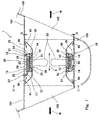
- a thrust generator 1 As shown in Fig. 1 , a thrust generator 1 according to Embodiment 1 is provided between cylindrical walls 101 provided in a hull 100.
- the thrust generator 1 squirts water W in the horizontal direction from openings 102 of the respective cylindrical walls 101 to generate thrust force.
- a central portion between the cylindrical walls 101 serves as an arrangement portion 103.
- a cylindrical housing 10, which is open at both sides in its axial direction, is fixed to the arrangement portion 103.
- the cylindrical walls 101 are formed as a pair of divided short tubes spaced apart from each other in the hull transverse direction, and a gap between the short tubes forms the arrangement portion 103.
- the cylindrical housing 10 is formed to have the same internal diameter as that of the cylindrical walls 101.
- the cylindrical housing 10 is fixed to the cylindrical walls 101 by welding or the like.
- the axial direction of the cylindrical housing 10 may be referred to as a left-right direction (and a surface facing in the left-right direction may be referred to as a side surface).
- a thruster body 20 is disposed inside the cylindrical housing 10.
- two flanges 12 and 13 protruding radially inward are provided at predetermined positions on the inner peripheral surface of the cylindrical housing 10.
- the fixing flange 12 for fixing the thruster body 20 is provided on the right side of Fig. 1
- the support flange 13 for supporting the thruster body 20 is provided on the left side of Fig. 1 .
- These flanges 12 and 13 are arranged away from each other in the axial direction X of a plurality of propeller blades 33 (which is the axial direction of the cylindrical housing 10).
- the flanges 12 and 13 are disposed at their respective positions, which are equally distant from the center of the propeller blades 33 in the axial direction X.
- the flanges 12 and 13 may be suitably disposed in accordance with, for example, the size of the thruster body 20.
- a side surface of the fixing flange 12 and a side surface of the support flange 13 that face each other are spaced apart from each other by a distance that is 0.2 times or more as great as the diameter of a propeller formed by the propeller blades 33.
- both the fixing flange 12 and the support flange 13 are continuous in the circumferential direction.
- the cylindrical housing 10 is required to include at least one flange (at least the fixing flange 12).
- the total number of fixing and support flanges 12 and 13 may be three or more.
- the cylindrical housing 10 includes only one of these flanges, i.e., the fixing flange 12.
- a protrusion functioning as the support flange 13 may be formed on the thruster body 20.
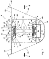
- a structure as shown in Fig. 19 is adopted so that the thruster body 20 can be pulled out of the cylindrical housing 10 to the left side.
- the thruster body 20 is pulled out of the cylindrical housing 10 to the right side.
- the thruster body 20 includes: an outer peripheral casing 22 disposed inside the cylindrical housing 10; an annular stator 25 disposed inside the outer peripheral casing 22; and a pair of annular side casings 23 fixed to respective side surfaces of the outer peripheral casing 22.
- the stator 25 is disposed in an annular groove that is opened radially inward and that is formed by the outer peripheral casing 22 and the side casings 23.
- the outer peripheral casing 22 is a cylindrical body, which is longer than a distance between a side surface of the fixing flange 12 and a side surface of the support flange 13 that face opposite to each other.
- a connecting portion 21 overlapping the fixing flange 12 in the axial direction X is provided in a manner to protrude radially outward.
- the connecting portion 21 is ring-shaped and continuous in the circumferential direction.
- the connecting portion 21 is fixed to the fixing flange 12 by fixing bolts 24 (one example of a fastening member of the present invention) in a state where the connecting portion 21 is in contact with the right side surface of the fixing flange 12 (i.e., in contact with the side surface facing the opposite side to the support flange 13). That is, the thruster body 20 is removably mounted to the fixing flange 12 by the fixing bolts 24, which penetrate the connecting portion 21.
- the outer peripheral surface of the outer peripheral casing 22 is supported by the inner peripheral surface of the support flange 13.
- An electric cable 27 extends through the side casing 23 provided at the opposite side to the connecting portion 21 (i.e., the side casing 23 at the left side).
- the electric cable 27 extends from the cylindrical housing 10 and is connected to armature coils 26 of the stator 25.
- the stator 25 is provided with a plurality of armature coils 26, which are formed in an annular manner.
- the electric cable 27 is inserted through a waterproof tube 17, which is provided between the cylindrical housing 10 and the side casing 23.
- the waterproof tube 17 is fixed to the cylindrical housing 10, and an end of the waterproof tube 17 is mounted to the side casing 23 by a bolt or the like.
- An annular rotor 30 is disposed inside the stator 25.
- the rotor 30 includes: an annular rotor core 31, to which a plurality of magnets are attached; and an annular rotor body 32 fitted to the outside of the rotor core 31.
- the rotor core 31 rotates, and thereby the rotor 30 rotates.
- the rotation speed, rotation direction, and the like of the rotor core 31 can be changed.
- stator 25 Heat from the stator 25 is transferred to the outer peripheral casing 22 by thermal conduction.
- the stator 25 and the rotor 30 form an electric motor.
- the stator 25 is cooled down by convection cooling at the outside of the outer peripheral casing 22 (i.e., at the outer periphery of the thruster body 20).
- the propeller blades 33 are provided on the inner peripheral surface of the rotor body 32. Each of the propeller blades 33 is formed to have such a shape that each propeller blade 33 can generate thrust force whether the propeller blade 33 rotates in a normal direction or a reverse direction.
- the base of each propeller blade 33 is mounted to the rotor body 32. This makes it possible to suppress the cavitation from the propeller blades 33. Therefore, noise and vibration due to the cavitation can be reduced.
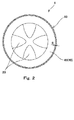
- the tip of each propeller blade 33 is positioned near the center of the rotor 30, and a central opening at the center of the rotor 30 is defined by all of the propeller tips (see Fig. 2 ).
- the propeller blades 33 (in this example, four propeller blades 33 as described below) are arranged at equally-spaced intervals in the circumferential direction.
- the rotor 30 is supported by water-lubricated bearings 50 and 51 provided at the inner periphery of the side casings 23.
- the rotor body 32 is provided with collar portions 34 and 35 extending to respective sides in the axial direction X from the central part of the rotor body 32 where the rotor core 31 is provided.
- the water-lubricated bearings 50 and 51 form water films between inner peripheral surfaces 52 of the respective water-lubricated bearings 50 and 51 and outer peripheral surfaces of the respective collar portions 34 and 35, thereby supporting a radial load exerted in the radial direction of the rotor body 32.
- the water-lubricated bearings 50 and 51 include facing surfaces 53, respectively.
- the facing surfaces 53 face respective side surfaces of the rotor body 32 in the axial direction X (i.e., annular surfaces extending radially outward from the bases of the collar portions 34 and 35).
- the water-lubricated bearings 50 and 51 form water films between the side surfaces of the rotor body 32 in the axial direction X and the facing surfaces 53, thereby supporting a thrust load exerted in the axial direction of the rotor body 32.
- the inner peripheral surfaces 52 of the water-lubricated bearings 50 and 51 serve as radial bearing surfaces
- the facing surfaces 53 of the water-lubricated bearings 50 and 51 serve as thrust bearing surfaces.
- the water-lubricated bearings 50 and 51 are provided in a manner to sandwich the rotor body 32 in the axial direction X, and the radial load and the thrust load exerted on the rotor 30 are supported by these water-lubricated bearings 50 and 51.
- the water-lubricated bearings 50 and 51 serve as plain bearings.
- water W flows from the facing surfaces 53 into a gap between the rotor core 31 and the stator 25. Thanks to the water-lubricated bearings 50 and 51, oil leakage problems are eliminated.
- a pair of fairing ducts 40 and 41 whose inner peripheral surfaces are continuous with the collar portions 34 and 35, is provided.
- the fairing ducts 40 and 41 are provided on the respective sides of the rotor 30 in the axial direction X. These fairing ducts 40 and 41 extend such that the more the distance from the rotor 30, the greater the diameter of each fairing duct.
- the fairing ducts 40 and 41 are formed such that the diameter of each fairing duct increases from a position corresponding to the inner peripheral surface of the rotor 30 (in the present embodiment, a position where the fairing duct forms a continuous surface together with the inner peripheral surface of the rotor 30) toward the cylindrical housing 10, and an end portion of the fairing duct is positioned adjacent to the inner periphery of the cylindrical housing 10. Further, the fairing ducts 40 and 41 are formed to extend from the positions of the water-lubricated bearings 50 and 51 to end portions of the cylindrical housing 10 in the axial direction (specifically, to the vicinity of the borders of the arrangement portion 103). These fairing ducts 40 and 41 are removably mounted by bolts (not shown) to the water-lubricated bearings 50 and 51, which form the respective side surfaces of the thruster body 20.
- the fairing duct 41 is provided such that a predetermined gap S is formed between the cylindrical housing 10 and the fairing duct 41 (the same is true of the fairing duct 40).
- the propeller blades 33 are positioned at the center of the fairing duct 41 (40). In this example, there are four propeller blades 33, and a space is formed at the center among the propeller blades 33.
- the support flange 13 is provided with a plurality of flow holes (liquid passing portions) 14, which are arranged in the circumferential direction.
- the plurality of flow holes 14 allow the water W to flow through the support flange 13.
- the fixing flange 12 is provided with a plurality of fixing holes (screw holes serving as female screws) 15 and a plurality of flow holes (liquid passing portions) 16.
- the fixing holes 15 and the flow holes 16 are arranged alternately and fully circumferentially.
- the fixing holes 15 are arranged at equal pitches in the circumferential direction, and the flow holes 16 are arranged at equal pitches between the fixing holes 15.
- the fixing bolts 24 are screwed into the fixing holes 15.
- the flow holes 16 are provided in an area where the fixing flange 12 and the connecting portion 21 overlap each other.
- the plurality of flow holes 16 allow the water W to flow through the fixing flange 12.
- the number of flow holes 14 formed in the support flange 13 is the same as the number of flow holes 16 formed in the fixing flange 12.
- the flow holes 14 and 16 are provided for allowing the water W to flow into an outer peripheral portion of the thruster body 20 in a state where the thruster body 20 is mounted to the fixing flange 12.
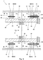
- Fig. 5 shows a state where the thruster body 20 is mounted to the fixing flange 12.
- a portion in contact with the fixing flange 12 and a portion in contact with the support flange 13 are formed as larger-diameter portions 45, whose widths correspond to the thicknesses of the flanges 12 and 13.
- the other portions of the outer peripheral casing 22 are formed as smaller-diameter portions 46.
- the larger-diameter portions 45 are connected to the smaller-diameter portions 46 via tapered surfaces.
- the connecting portion 21 of the thruster body 20 is brought into contact with the right side surface of the fixing flange 12. Then, the fixing bolts 24 are inserted in bolt insertion holes 28 formed in the connecting portion 21, and the fixing bolts 24 are further screwed into the fixing holes 15 (screw holes serving as female screws) formed in the fixing flange 12. As a result, the thruster body 20 is fixed to the fixing flange 12.
- the fixing of the thruster body 20 is realized by the surface pressure between the contact surface of the connecting portion 21 and the contact surface of the fixing flange 12, the surface pressure occurring when the connecting portion 21 is fastened to the fixing flange 12 by the fixing bolts 24.
- FIG. 5 shows only one of the fixing bolts 24, which are arranged in the circumferential direction.
- the connecting portion 21 of the thruster body 20 is fixed to the right side surface of the fixing flange 12 as shown in Fig. 5 . Accordingly, in the case of removing the thruster body 20, the connecting portion 21 is pulled out to the right side of the drawing (see Fig. 6 ).
- portions of the outer peripheral casing 22, other than the portion whose width corresponds to the thickness of the support flange 13 and the portion whose width corresponds to the thickness of the fixing flange 12, are formed as the smaller-diameter portions 46. Therefore, at the time of removing or mounting the thruster body 20, the thruster body 20 can be readily moved in the axial direction X thanks to the large gaps except at the position where the thruster body 20 is fixed.
- the fixing flange 12 and the support flange 13 are provided with the flow holes 16 and the flow holes 14.
- the connecting portion 21 is provided with a plurality of flow holes (liquid passing portions) 29 at positions coinciding with the positions of the flow holes 16 in the fixing flange 12. Therefore, as shown in Fig. 5 , the flow holes 16 and 29 are in communication with each other in a state where the connecting portion 21 is fixed to the fixing flange 12.
- These flow holes 16 and 29 form a cooling flow passage 90 for water-cooling the outer peripheral casing 22 between the fixing flange 12 and the support flange 13 and between the outer peripheral casing 22 and the cylindrical housing 10.
- the flow of water W along the cooling flow passage 90 is generated by the flow of water W that squirts out to one side through one of the openings 102 of the cylindrical wall 101 when the propeller blades 33 are rotated.
- the flow of water W is generated either to the right or left in accordance with the rotation direction of the propeller blades 33.
- Fig. 6 shows a state where the thrust generator 1 according to Embodiment 1 is disassembled.
- the fairing ducts 40 and 41 fixed to the water-lubricated bearings 50 and 51 by bolts (not shown) are removed.
- the fairing ducts 40 and 41 can be removed in the axial direction X through the openings 102 of the cylindrical wall 101.
- the fixing bolts 24 fixing the connecting portion 21 of the thruster body 20 to the fixing flange 12 are removed.
- the electric cable 27 is removed at a hull-side connection (not shown), and the waterproof tube 17 through which the electric cable 27 is inserted is removed from the side casing 23.
- components including the propeller blades 33 are integrally pulled out as the thruster body 20 to the right side.
- the pull-out of the thruster body 20 can be readily performed, for example, by laying rails on the inner bottom surfaces of the cylindrical housing 10 and the cylindrical wall 101 and moving the thruster body 20 along the rails in the horizontal direction.
- the work of removing and mounting components including the rotor 30 and the propeller blades 33 integrally as the thruster body 20 can be entirely performed outside the ship. Accordingly, between the hull 100 and the thrust generator 1, components other than the electric cable 27 need not be waterproofed, and thus the number of components that require waterproofing can be minimized.
- components including the propeller blades 33 can be integrally removed as the thruster body 20, and the maintenance can be readily performed on the sea or in a factory.
- Fig. 7 is a longitudinal sectional view of a thrust generator 2 according to Embodiment 2.
- water-lubricated bearings 60 and 61 are static pressure bearings, which forcibly feed water W. It should be noted that the same components as those of the thrust generator 1 of Embodiment 1 are denoted by the same reference signs as those used in Embodiment 1, and a detailed description of such components is omitted.
- buffer spaces 62 are provided at the outer periphery of the water-lubricated bearings 60 and 61.
- Water W is forcibly fed to the buffer spaces 62 through pipes 63.
- the pipes 63 are connected to a pump (not shown) provided inside the ship via connection joints 64 provided on the cylindrical housing 10.
- FIG. 8 As shown in a cross-sectional view of Fig. 8 taken along a line VIII-VIII, the waterproof tube 17, through which the electric cable 27 is inserted, is provided on the upper part of the side casing 23, and the pipe 63 is provided on the lower part of the water-lubricated bearing 60.
- This cross-sectional view shows a state where the support flange 13 is seen around the side casing 23, and also, the flow holes 14 formed in the support flange 13 are seen.
- the pipe 63 is provided also on the lower part of the water-lubricated bearing 61 provided at the opposite side of the outer peripheral casing 22.
- This cross-sectional view shows a state where the connecting portion 21 of the outer peripheral casing 22 is seen around the side casing 23, and also, the flow holes 29 of the connecting portion 21 are seen.
- the flow holes 29 are in communication with the flow holes 16 formed in the fixing flange 12.
- the thrust generator 2 stable water films can always be formed between the rotor 30 and the bearing surfaces of the water-lubricated bearings 60 and 61. Therefore, the rotor 30 can be supported in a stable manner even under the condition that the thrust generator 2 is used for a long period of time with low speed rotation, for example, in a ship staying at a fixed point.
- the connecting portion 21, the fixing flange 12, and the support flange 13 are provided with the flow holes 29, 16, and 14, respectively (see Fig. 5 ). Accordingly, when the propeller blades 33 are rotated and a water flow is generated, water W (cooling liquid) flows in toward the thruster body 20 through the gap S formed between the cylindrical housing 10 and one of the fairing ducts 40 and 41, and the water W flows through the cooling flow passage 90. In this manner, the outer surface of the outer peripheral casing 22 can be cooled down efficiently ( Fig. 5 ).
- the electric cable 27, the waterproof tube 17, and the connection joints 64 may be removed after removing the fairing ducts 40 and 41, and similar to Fig. 6 , the fixing bolts 24 fixing the connecting portion 21 of the thruster body 20 to the fixing flange 12 may be removed. Consequently, components including the propeller blades 33 can be integrally removed as the thruster body 20 in the axial direction X through the opening 102 of the cylindrical wall 101. Therefore, the maintenance of the components including the propeller blades 33 can be readily performed.
- Fig. 10 is a longitudinal sectional view showing a thrust generator 3 according to Embodiment 3.
- Embodiment 3 shows an example where instead of adopting the direct connection using the electric cable 27 as in the thrust generator 1 of Embodiment 1, an underwater connector 71 is provided on an electric cable 70.
- the electric cable 70 extends from the cylindrical housing 10 and is connected to the stator 25. It should be noted that the same components as those of the thrust generator 1 of Embodiment 1 are denoted by the same reference signs as those used in Embodiment 1, and a detailed description of such components is omitted.
- one of the side casings 23 is provided with an output cable 73, which is provided with a socket 72 of the underwater connector 71.
- the cylindrical wall 101 is provided with an input cable 75, whose distal end is provided with a plug 74 of the underwater connector 71.
- the underwater connector 71 shown in Fig. 10 is in a state where the plug 74 and the socket 72 are connected.
- components including the propeller blades 33 can be integrally removed in the axial direction X as the thruster body 20, by removing the fairing ducts 40 and 41, pulling the plug 74 of the underwater connector 71 out of the socket 72, and removing the fixing bolts 24, which fix the connecting portion 21 of the thruster body 20 to the fixing flange 12.
- the connecting portion 21, the fixing flange 12, and the support flange 13 are provided with the flow holes 29, 16, and 14, respectively (see Fig. 5 ). Accordingly, when the propeller blades 33 are rotated and a water flow is generated, water W (cooling liquid) flows in toward the thruster body 20 through the gap S formed between the cylindrical housing 10 and one of the fairing ducts 40 and 41, and the water W flows through the cooling flow passage 90. In this manner, the outer surface of the outer peripheral casing 22 can be cooled down efficiently ( Fig. 5 ).
- Fig. 11 is a longitudinal sectional view of a thrust generator 4 according to Embodiment 4.
- Embodiment 4 shows an example where instead of the fixing flange 12 and the support flange 13 of the thrust generator 1 of Embodiment 1, a fixing flange 80, a support flange 81, and flow passage forming members are provided, expecting further improvement in the cooling effect.
- the same components as those of the thrust generator 1 of Embodiment 1 are denoted by the same reference signs as those used in Embodiment 1, and a detailed description of such components is omitted.
- the fixing flange 80 and the support flange 81 both of which protrude radially inward, are provided on the inner peripheral surface of the cylindrical housing 10, and flow passage forming flanges 82 and 83, which serve as the flow passage forming members, are provided between the fixing flange 80 and the support flange 81.
- the internal diameters of the respective flow passage forming flanges 82 and 83 are slightly greater than those of the fixing flange 80 and the support flange 81, and thereby interference at the time of removing or mounting the thruster body 20 in the axial direction X is prevented.
- flow holes (liquid passing portions) 84 are formed only in the lower part of the support flange 81 below the central part of the support flange 81. That is, the flow holes 84 are disposed within a part of the support flange 81 in the circumferential direction. The flow holes 84 are arranged at equal pitches. The plurality of flow holes 84 allow the water W to flow through the support flange 81. As shown in Fig. 13 , the fixing flange 80 is provided with the plurality of fixing holes 15, which are arranged fully circumferentially, and flow holes (liquid passing portions) 85 are formed only in the upper part of the fixing flange 80 above the central part of the fixing flange 80.
- the flow holes 85 are disposed within a part of the fixing flange 80 in the circumferential direction.
- the plurality of flow holes 85 allow the water W to flow through the fixing flange 80.
- the fixing holes 15 are arranged at equal pitches in the circumferential direction, and the flow holes 85 are arranged at equal pitches between the upper fixing holes 15.
- the number of flow holes 84 formed in the support flange 81 is the same as the number of flow holes 85 formed in the fixing flange 80.
- the right-side flow passage forming flange 82 which faces the fixing flange 80, includes an opening 86.
- the opening 86 is formed by cutting away a predetermined portion of the lower part of the flow passage forming flange 82. Specifically, the opening 86 is positioned at the opposite side to the flow holes 85 of the fixing flange 80 with respect to the central axis of the cylindrical housing 10. In this example, the opening 86 is formed by cutting away a 30° portion of the lower part of the flow passage forming flange 82.
- the left-side flow passage forming flange 83 which faces the support flange 81, includes an opening 87.
- the opening 87 is formed by cutting away a predetermined portion of the upper part of the flow passage forming flange 83. Specifically, the opening 87 is positioned at the opposite side to the flow holes 84 of the support flange 81 with respect to the central axis of the cylindrical housing 10. In this example, the opening 87 is formed by cutting away a 30° portion of the upper part of the flow passage forming flange 83.
- Fig. 16 shows a state where the thruster body 20 is mounted to the fixing flange 80.
- a portion in contact with the fixing flange 80 and a portion in contact with the support flange 81 are formed as larger-diameter portions 45, whose widths correspond to the thicknesses of the flanges 80 and 81.
- the other portions of the outer peripheral casing 22 are formed as smaller-diameter portions 46. In this manner, gaps (clearances) between the outer peripheral casing 22 and the fixing and support flanges 80 and 81 when the thruster body 20 is moved in the axial direction X are increased, which allows the thruster body 20 to be readily moved in the axial direction X.
- the connecting portion 21 of the thruster body 20 is brought into contact with the right side surface of the fixing flange 80.
- the fixing bolts 24 are inserted in the bolt insertion holes 28 formed in the connecting portion 21, and the fixing bolts 24 are further screwed into the fixing holes 15 (screw holes serving as female screws) formed in the fixing flange 80.
- the thruster body 20 is fixed to the fixing flange 80.
- the fixing of the thruster body 20 is realized by the surface pressure between the contact surface of the connecting portion 21 and the contact surface of the fixing flange 80, the surface pressure occurring when the connecting portion 21 is fastened to the fixing flange 80 by the fixing bolts 24.
- FIG. 16 shows only one of the fixing bolts 24, which are arranged in the circumferential direction. Also in the present embodiment, the connecting portion 21 of the thruster body 20 is fixed to the right side surface of the fixing flange 80 as shown in Fig. 16 . Accordingly, in the case of removing the thruster body 20, the connecting portion 21 is pulled out to the right side of the drawing (same as Fig. 6 ).
- portions of the outer peripheral casing 22, other than the portion whose width corresponds to the thickness of the support flange 81 and the portion whose width corresponds to the thickness of the fixing flange 80, are formed as the smaller-diameter portions 46. Therefore, at the time of removing or mounting the thruster body 20, the thruster body 20 can be readily moved in the axial direction X thanks to the large gaps except at the position where the thruster body 20 is fixed.
- the upper part of the connecting portion 21 and the upper part of the fixing flange 80 are provided with the flow holes 29 and 85, respectively.
- the lower part of the support flange 81 is provided with the flow holes 84.
- the lower part of the right-side flow passage forming flange 82 is provided with the opening 86.
- the upper part of the left-side flow passage forming flange 83 is provided with the opening 87.
- these holes and openings form a cooling flow passage 90 for water-cooling the outer peripheral casing 22 between the fixing flange 80 and the support flange 81 and between the outer peripheral casing 22 and the cylindrical housing 10.
- the cooling flow passage 90 allows the water W (cooling liquid) to flow in the circumferential direction.
- water W cooling liquid
- arrows 91 to 94 in Fig. 16 when the propeller blades 33 are rotated and a water flow is generated, water W flows in toward the thruster body 20 through the gap S ( Fig. 11 ) formed between the cylindrical housing 10 and one of the fairing ducts 40 and 41, and the water W flows through the cooling flow passage 90.
- the water W from the right side of Fig.
- the water W flows between the flow passage forming flange 82 and the fixing flange 12 downward.
- the water W flows between the flow passage forming flanges 82 and 83 upward.
- the water W flows between the support flange 81 and the flow passage forming flange 83 downward, and flows out of the flow holes 84 of the support flange 81.
- the arrows 91 to 94 are double-headed arrows, intending to include a case where the water W is fed from the flow holes 84 of the support flange 81.
- the cross-sectional area of the cooling flow passage 90 of Embodiment 4 is less than that of each cooling flow passage of the thrust generators 1 to 3 of Embodiments 1 to 3 (i.e., less than the area of the cooling flow passage between the fixing flange 12 and the support flange 13 in the circumferential direction).
- the flow velocity of the cooling water flowing along the outer surface of the outer peripheral casing 22 increases, which makes it possible to further improve the cooling efficiency.
- the thruster body 20 can be readily removed from the hull or the like for maintenance.
- the propeller blades 33 are rotated to generate thrust force, a water flow from the fixing flange 80 side or the support flange 81 side is generated and passes through the cooling flow passage 90 formed around the outer peripheral casing 22.
- the stator 25 can be cooled down efficiently via the outer peripheral casing 22. This makes it possible to improve the efficiency of the electric motor.
- the thruster body 20 including the propeller blades 33 can be integrally removed as a unit from the cylindrical housing 10, which is fixed to the hull or the like. This makes it possible to greatly improve the maintainability of the thrust generators 1 to 4, which are rim drive thrusters.
- the outer peripheral casing 22 can be efficiently cooled down between the fixing flange (12 or 80) fixing the thruster body 20 to the cylindrical housing 10 and the support flange (13 or 81) supporting the thruster body 20, the efficiency in cooling down the electric motor of each of the thrust generators 1 to 4 can be improved, and thereby the efficiency as the thruster can be improved.
- the flow holes 14 and 84 form the liquid passing portions.
- the manner of allowing the cooling liquid to pass through is not limited to the above-described embodiments.
- groove-shaped liquid passing portions may be adopted to allow the cooling liquid to pass through.
- the thrust generators 1 to 4 are each provided on the cylindrical wall 101 of the hull 100 as a side thruster of a ship.
- the thrust generators 1 to 4 may be alternatively used in other structures, and the use thereof is not limited to a thrust generator of a ship. That is, the liquid squirted by each thrust generator is not limited to water, but may be a different liquid.
- the fixing flange (12 or 80) it is not essential for the fixing flange (12 or 80) to be continuous in the circumferential direction.
- a plurality of pieces scattered in the circumferential direction may serve as the fixing flange. In this case, gaps between the pieces may serve as the liquid passing portions of the fixing flange.
- the support flange (13 or 81) it is not essential for the support flange (13 or 81) to be continuous in the circumferential direction.
- a plurality of pieces scattered in the circumferential direction may serve as the support flange. In this case, gaps between the pieces may serve as the liquid passing portions of the fixing flange.
- the connecting portion 21 it is not essential for the connecting portion 21 to be ring-shaped and continuous in the circumferential direction. A plurality of pieces scattered in the circumferential direction may serve as the connecting portion 21.
- the flow holes (16 or 85) formed in the fixing flange (12 or 80) may be arranged at positions that are radially outward from the connecting portion 21, and the connecting portion 21 need not be provided with the flow holes 29.
- a spacer 201 may be interposed between the fixing flange (12 or 80) and the connecting portion 21.
- Annular members with various cross-sectional shapes are each usable as the spacer 201.
- a plurality of pieces scattered in the circumferential direction may serve as the spacer 201.
- a check plate 202 may be fixed to a side surface of the outer peripheral casing 22 by bolts 203, and the peripheral portion of the check plate 202 may serve as the connecting portion 21.
- the peripheral portion of one of the side casings 23 may protrude from the outer peripheral casing 22, and the protruding portion of the side casing 23 may serve as the connecting portion 21.
- the connecting portion 21, which overlaps the fixing flange (12 or 80) in the axial direction of the cylindrical housing 10, may be in contact with the left side surface of the fixing flange (the side surface at the support flange 13 side) as shown in Fig. 19 .
- the outer portion of the outer peripheral casing 22 can form the connecting portion 21.
- the fixing bolts 24 penetrate the fixing flange (12 or 80), and are screwed into screw holes 204 formed in the connecting portion 21.
- the thruster body 20 may include the connecting portion 21 overlapping the fixing flange (12 or 80) in the axial direction of the cylindrical housing 10.
- the outer peripheral surface of the outer peripheral casing 22 may be provided with screw holes 205, and the fixing bolts 24 penetrating the cylindrical housing 10 and the fixing flange in the radial direction of the cylindrical housing 10 may be screwed into the screw holes 205.
- the removal or mounting of the thruster body 20 can be performed only through work outside the ship.
- the thrust generator according to the present invention is useful as a thruster of a ship or the like.
Landscapes
- Chemical & Material Sciences (AREA)
- Engineering & Computer Science (AREA)
- Combustion & Propulsion (AREA)
- Mechanical Engineering (AREA)
- Ocean & Marine Engineering (AREA)
- Other Liquid Machine Or Engine Such As Wave Power Use (AREA)
- Structures Of Non-Positive Displacement Pumps (AREA)
- Hydraulic Turbines (AREA)
Applications Claiming Priority (2)
| Application Number | Priority Date | Filing Date | Title |
|---|---|---|---|
| JP2013122922A JP6204709B2 (ja) | 2013-06-11 | 2013-06-11 | 推力発生装置 |
| PCT/JP2014/003108 WO2014199635A1 (ja) | 2013-06-11 | 2014-06-11 | 推力発生装置 |
Publications (2)
| Publication Number | Publication Date |
|---|---|
| EP3009342A1 true EP3009342A1 (de) | 2016-04-20 |
| EP3009342A4 EP3009342A4 (de) | 2017-04-19 |
Family
ID=52021947
Family Applications (1)
| Application Number | Title | Priority Date | Filing Date |
|---|---|---|---|
| EP14811555.3A Withdrawn EP3009342A4 (de) | 2013-06-11 | 2014-06-11 | Schubkrafterzeugungsvorrichtung |
Country Status (5)
| Country | Link |
|---|---|
| EP (1) | EP3009342A4 (de) |
| JP (1) | JP6204709B2 (de) |
| KR (1) | KR101707558B1 (de) |
| CN (1) | CN105209337B (de) |
| WO (1) | WO2014199635A1 (de) |
Cited By (3)
| Publication number | Priority date | Publication date | Assignee | Title |
|---|---|---|---|---|
| GR1009624B (el) * | 2018-11-02 | 2019-10-23 | Λαλιζας Ανωνυμη Εταιρεια Κατασκευης Και Εμποριας Ναυτιλιακων Σωστικων Και Αθλητικων Ειδων | Προωστηρας θαλασσιου σκαφους αποτελουμενος απο πτυσσομενο στατορα δυο ή περισσοτερων μερων και ροτορα την προπελα που εχει στην περιφερεια της εγκατεστημενους μονιμους μαγνητες |
| WO2022188988A1 (en) | 2021-03-12 | 2022-09-15 | Wärtsilä Netherlands B.V. | A propulsion assembly for a marine vessel |
| US12595036B2 (en) | 2022-04-08 | 2026-04-07 | Taiga Motors Inc. | Rim-driven motor for personal watercraft |
Families Citing this family (5)
| Publication number | Priority date | Publication date | Assignee | Title |
|---|---|---|---|---|
| KR102444501B1 (ko) * | 2019-11-12 | 2022-09-16 | 한국전기연구원 | 회전 전기기기 및 그를 가지는 추진시스템 |
| CN112339965B (zh) * | 2020-11-26 | 2025-02-11 | 中国船舶重工集团公司第七0四研究所 | 可湿坞拆卸维修的弹性安装式无轴侧推装置 |
| CN114348225B (zh) * | 2021-12-22 | 2022-11-18 | 中国人民解放军海军工程大学 | 一种减振降噪的无轴侧推装置和流道系统 |
| CN115158622B (zh) * | 2022-06-15 | 2023-05-23 | 中国船舶重工集团公司第七一九研究所 | 适应复杂水域的集成电机推进装置 |
| KR102773304B1 (ko) * | 2022-11-25 | 2025-02-27 | 국방과학연구소 | 해수를 통한 냉각이 가능한 수중 운동체의 추진 장치 |
Family Cites Families (12)
| Publication number | Priority date | Publication date | Assignee | Title |
|---|---|---|---|---|
| US1326730A (en) * | 1919-12-30 | Shaetless propeller | ||
| US6692319B2 (en) * | 2002-03-29 | 2004-02-17 | Alstom Shilling Robotics | Thruster for submarine vessels |
| US7220154B2 (en) * | 2003-11-13 | 2007-05-22 | Sword Marine Technology, Inc. | Outboard jet drive marine propulsion system |
| JP4795144B2 (ja) * | 2006-07-05 | 2011-10-19 | 川崎重工業株式会社 | 水力発電装置 |
| JP5100370B2 (ja) * | 2007-12-28 | 2012-12-19 | 川崎重工業株式会社 | 推力発生装置 |
| ES2650986T3 (es) * | 2008-05-27 | 2018-01-23 | Siemens Aktiengesellschaft | Turbomáquina con al menos dos rotores |
| CN101546931B (zh) * | 2009-04-28 | 2011-07-27 | 中国船舶重工集团公司第七一二研究所 | 一种集成推进器 |
| NO331651B1 (no) * | 2009-05-20 | 2012-02-13 | Rolls Royce Marine As | Opplagring av propellenhet for et fartøy |
| JP5432606B2 (ja) * | 2009-06-25 | 2014-03-05 | 川崎重工業株式会社 | 推力発生装置 |
| JP5281500B2 (ja) * | 2009-06-25 | 2013-09-04 | 川崎重工業株式会社 | 推力発生装置 |
| DE102009040471B4 (de) * | 2009-09-08 | 2016-07-21 | Tutech Innovation Gmbh | Mechanisch angetriebener Schiffpropulsor mit hohem Wirkungsgrad |
| NO335623B1 (no) * | 2009-11-25 | 2015-01-12 | Rolls Royce Marine As | Skyvekraftenhet og fremgangsmåte for installasjon av en skyvekraftenhet |
-
2013
- 2013-06-11 JP JP2013122922A patent/JP6204709B2/ja active Active
-
2014
- 2014-06-11 WO PCT/JP2014/003108 patent/WO2014199635A1/ja not_active Ceased
- 2014-06-11 EP EP14811555.3A patent/EP3009342A4/de not_active Withdrawn
- 2014-06-11 KR KR1020157036331A patent/KR101707558B1/ko active Active
- 2014-06-11 CN CN201480021405.1A patent/CN105209337B/zh active Active
Non-Patent Citations (1)
| Title |
|---|
| See references of WO2014199635A1 * |
Cited By (3)
| Publication number | Priority date | Publication date | Assignee | Title |
|---|---|---|---|---|
| GR1009624B (el) * | 2018-11-02 | 2019-10-23 | Λαλιζας Ανωνυμη Εταιρεια Κατασκευης Και Εμποριας Ναυτιλιακων Σωστικων Και Αθλητικων Ειδων | Προωστηρας θαλασσιου σκαφους αποτελουμενος απο πτυσσομενο στατορα δυο ή περισσοτερων μερων και ροτορα την προπελα που εχει στην περιφερεια της εγκατεστημενους μονιμους μαγνητες |
| WO2022188988A1 (en) | 2021-03-12 | 2022-09-15 | Wärtsilä Netherlands B.V. | A propulsion assembly for a marine vessel |
| US12595036B2 (en) | 2022-04-08 | 2026-04-07 | Taiga Motors Inc. | Rim-driven motor for personal watercraft |
Also Published As
| Publication number | Publication date |
|---|---|
| CN105209337B (zh) | 2018-01-12 |
| JP2014240224A (ja) | 2014-12-25 |
| CN105209337A (zh) | 2015-12-30 |
| KR101707558B1 (ko) | 2017-02-16 |
| KR20160018580A (ko) | 2016-02-17 |
| WO2014199635A1 (ja) | 2014-12-18 |
| JP6204709B2 (ja) | 2017-09-27 |
| EP3009342A4 (de) | 2017-04-19 |
Similar Documents
| Publication | Publication Date | Title |
|---|---|---|
| EP3009342A1 (de) | Schubkrafterzeugungsvorrichtung | |
| US8708668B2 (en) | Thrust generating apparatus | |
| JP5281500B2 (ja) | 推力発生装置 | |
| EP2949574B1 (de) | Pod-Antriebseinheit eines Schiffs | |
| JP5100370B2 (ja) | 推力発生装置 | |
| KR100927059B1 (ko) | 모터나 발전기를 포함한 내충격 전기 해양 엔진 | |
| CN104718131B (zh) | 用于船舶的推进系统 | |
| US20150071780A1 (en) | Propulsion apparatus for ship and ship having the same | |
| KR20120111209A (ko) | 선박용 추진장치 및 이를 포함하는 선박 | |
| CN114348225B (zh) | 一种减振降噪的无轴侧推装置和流道系统 | |
| JP5804312B2 (ja) | 船舶用電気推進装置及び船舶 | |
| KR101205939B1 (ko) | 선박용 추진장치 및 이를 포함하는 선박 | |
| EP3552917A1 (de) | Getriebeanordnung |
Legal Events
| Date | Code | Title | Description |
|---|---|---|---|
| PUAI | Public reference made under article 153(3) epc to a published international application that has entered the european phase |
Free format text: ORIGINAL CODE: 0009012 |
|
| 17P | Request for examination filed |
Effective date: 20151120 |
|
| AK | Designated contracting states |
Kind code of ref document: A1 Designated state(s): AL AT BE BG CH CY CZ DE DK EE ES FI FR GB GR HR HU IE IS IT LI LT LU LV MC MK MT NL NO PL PT RO RS SE SI SK SM TR |
|
| AX | Request for extension of the european patent |
Extension state: BA ME |
|
| DAX | Request for extension of the european patent (deleted) | ||
| A4 | Supplementary search report drawn up and despatched |
Effective date: 20170320 |
|
| RIC1 | Information provided on ipc code assigned before grant |
Ipc: B63H 21/17 20060101ALI20170314BHEP Ipc: B63H 1/12 20060101AFI20170314BHEP Ipc: B63H 25/42 20060101ALI20170314BHEP |
|
| GRAP | Despatch of communication of intention to grant a patent |
Free format text: ORIGINAL CODE: EPIDOSNIGR1 |
|
| STAA | Information on the status of an ep patent application or granted ep patent |
Free format text: STATUS: GRANT OF PATENT IS INTENDED |
|
| INTG | Intention to grant announced |
Effective date: 20180222 |
|
| STAA | Information on the status of an ep patent application or granted ep patent |
Free format text: STATUS: THE APPLICATION IS DEEMED TO BE WITHDRAWN |
|
| 18D | Application deemed to be withdrawn |
Effective date: 20180705 |