EP3009596B1 - Système de passage de flux secondaire pour un ensemble rotor d'un moteur à turbine à gaz - Google Patents
Système de passage de flux secondaire pour un ensemble rotor d'un moteur à turbine à gaz Download PDFInfo
- Publication number
- EP3009596B1 EP3009596B1 EP15185751.3A EP15185751A EP3009596B1 EP 3009596 B1 EP3009596 B1 EP 3009596B1 EP 15185751 A EP15185751 A EP 15185751A EP 3009596 B1 EP3009596 B1 EP 3009596B1
- Authority
- EP
- European Patent Office
- Prior art keywords
- rotor
- channel
- rotor assembly
- adjacent
- passage
- Prior art date
- Legal status (The legal status is an assumption and is not a legal conclusion. Google has not performed a legal analysis and makes no representation as to the accuracy of the status listed.)
- Active
Links
Images


Classifications
-
- F—MECHANICAL ENGINEERING; LIGHTING; HEATING; WEAPONS; BLASTING
- F01—MACHINES OR ENGINES IN GENERAL; ENGINE PLANTS IN GENERAL; STEAM ENGINES
- F01D—NON-POSITIVE DISPLACEMENT MACHINES OR ENGINES, e.g. STEAM TURBINES
- F01D5/00—Blades; Blade-carrying members; Heating, heat-insulating, cooling or antivibration means on the blades or the members
- F01D5/12—Blades
- F01D5/14—Form or construction
- F01D5/18—Hollow blades, i.e. blades with cooling or heating channels or cavities; Heating, heat-insulating or cooling means on blades
-
- F—MECHANICAL ENGINEERING; LIGHTING; HEATING; WEAPONS; BLASTING
- F01—MACHINES OR ENGINES IN GENERAL; ENGINE PLANTS IN GENERAL; STEAM ENGINES
- F01D—NON-POSITIVE DISPLACEMENT MACHINES OR ENGINES, e.g. STEAM TURBINES
- F01D5/00—Blades; Blade-carrying members; Heating, heat-insulating, cooling or antivibration means on the blades or the members
- F01D5/02—Blade-carrying members, e.g. rotors
- F01D5/06—Rotors for more than one axial stage, e.g. of drum or multiple disc type; Details thereof, e.g. shafts, shaft connections
- F01D5/066—Connecting means for joining rotor-discs or rotor-elements together, e.g. by a central bolt, by clamps
-
- F—MECHANICAL ENGINEERING; LIGHTING; HEATING; WEAPONS; BLASTING
- F01—MACHINES OR ENGINES IN GENERAL; ENGINE PLANTS IN GENERAL; STEAM ENGINES
- F01D—NON-POSITIVE DISPLACEMENT MACHINES OR ENGINES, e.g. STEAM TURBINES
- F01D5/00—Blades; Blade-carrying members; Heating, heat-insulating, cooling or antivibration means on the blades or the members
- F01D5/02—Blade-carrying members, e.g. rotors
- F01D5/08—Heating, heat-insulating or cooling means
- F01D5/081—Cooling fluid being directed on the side of the rotor disc or at the roots of the blades
- F01D5/084—Cooling fluid being directed on the side of the rotor disc or at the roots of the blades the fluid circulating at the periphery of a multistage rotor, e.g. of drum type
-
- F—MECHANICAL ENGINEERING; LIGHTING; HEATING; WEAPONS; BLASTING
- F01—MACHINES OR ENGINES IN GENERAL; ENGINE PLANTS IN GENERAL; STEAM ENGINES
- F01D—NON-POSITIVE DISPLACEMENT MACHINES OR ENGINES, e.g. STEAM TURBINES
- F01D5/00—Blades; Blade-carrying members; Heating, heat-insulating, cooling or antivibration means on the blades or the members
- F01D5/02—Blade-carrying members, e.g. rotors
- F01D5/08—Heating, heat-insulating or cooling means
- F01D5/085—Heating, heat-insulating or cooling means cooling fluid circulating inside the rotor
-
- F—MECHANICAL ENGINEERING; LIGHTING; HEATING; WEAPONS; BLASTING
- F04—POSITIVE - DISPLACEMENT MACHINES FOR LIQUIDS; PUMPS FOR LIQUIDS OR ELASTIC FLUIDS
- F04D—NON-POSITIVE-DISPLACEMENT PUMPS
- F04D29/00—Details, component parts, or accessories
- F04D29/26—Rotors specially for elastic fluids
- F04D29/32—Rotors specially for elastic fluids for axial flow pumps
- F04D29/321—Rotors specially for elastic fluids for axial flow pumps for axial flow compressors
-
- F—MECHANICAL ENGINEERING; LIGHTING; HEATING; WEAPONS; BLASTING
- F04—POSITIVE - DISPLACEMENT MACHINES FOR LIQUIDS; PUMPS FOR LIQUIDS OR ELASTIC FLUIDS
- F04D—NON-POSITIVE-DISPLACEMENT PUMPS
- F04D29/00—Details, component parts, or accessories
- F04D29/58—Cooling; Heating; Diminishing heat transfer
- F04D29/582—Cooling; Heating; Diminishing heat transfer specially adapted for elastic fluid pumps
- F04D29/584—Cooling; Heating; Diminishing heat transfer specially adapted for elastic fluid pumps cooling or heating the machine
-
- F—MECHANICAL ENGINEERING; LIGHTING; HEATING; WEAPONS; BLASTING
- F05—INDEXING SCHEMES RELATING TO ENGINES OR PUMPS IN VARIOUS SUBCLASSES OF CLASSES F01-F04
- F05D—INDEXING SCHEME FOR ASPECTS RELATING TO NON-POSITIVE-DISPLACEMENT MACHINES OR ENGINES, GAS-TURBINES OR JET-PROPULSION PLANTS
- F05D2260/00—Function
- F05D2260/20—Heat transfer, e.g. cooling
- F05D2260/205—Cooling fluid recirculation, i.e. after cooling one or more components is the cooling fluid recovered and used elsewhere for other purposes
-
- F—MECHANICAL ENGINEERING; LIGHTING; HEATING; WEAPONS; BLASTING
- F05—INDEXING SCHEMES RELATING TO ENGINES OR PUMPS IN VARIOUS SUBCLASSES OF CLASSES F01-F04
- F05D—INDEXING SCHEME FOR ASPECTS RELATING TO NON-POSITIVE-DISPLACEMENT MACHINES OR ENGINES, GAS-TURBINES OR JET-PROPULSION PLANTS
- F05D2260/00—Function
- F05D2260/20—Heat transfer, e.g. cooling
- F05D2260/221—Improvement of heat transfer
-
- Y—GENERAL TAGGING OF NEW TECHNOLOGICAL DEVELOPMENTS; GENERAL TAGGING OF CROSS-SECTIONAL TECHNOLOGIES SPANNING OVER SEVERAL SECTIONS OF THE IPC; TECHNICAL SUBJECTS COVERED BY FORMER USPC CROSS-REFERENCE ART COLLECTIONS [XRACs] AND DIGESTS
- Y02—TECHNOLOGIES OR APPLICATIONS FOR MITIGATION OR ADAPTATION AGAINST CLIMATE CHANGE
- Y02T—CLIMATE CHANGE MITIGATION TECHNOLOGIES RELATED TO TRANSPORTATION
- Y02T50/00—Aeronautics or air transport
- Y02T50/60—Efficient propulsion technologies, e.g. for aircraft
Definitions
- the present disclosure relates to a gas turbine engine and, more particularly, to a secondary flowpath system for a rotor of the gas turbine engine and method of operation.
- Gas turbine rotor assemblies include successive rows of blades that extend from respective rotor disks that may be arranged in an axially stacked configuration.
- the rotor stack may be assembled through a multitude of systems such as fasteners, fusion, tie-shafts and various combinations thereof.
- Gas turbine rotor assemblies operate in an environment where significant pressure and temperature differentials exist across component boundaries that primarily separate a core gas flow path, a secondary cooling flow path, and relatively static cavities such as rotor bores located axially between rotor disks.
- TMF thermo-mechanical fatigue
- the components may be of a heavier-than-optimal weight to prevent TMF and achieve the desired performance requirements.
- EP 2586969 A2 discloses a spoked rotor for a gas turbine engine.
- a rotor assembly of a gas turbine engine according to one aspect of the invention is provided by claim 1.
- the passage is annular.
- the rotor is a spoked rotor including a plurality of circumferentially spaced first spokes generally located radially between the platforms and the rotor disks, and the first channel is one of a plurality of first channels with each first channel defined circumferentially between adjacent first spokes.
- the spacer includes radially inner and outer rings and a plurality of circumferentially spaced second spokes spanning radially between the inner and outer rings, and the second channel is one of a plurality of second channels with each second channel defined circumferentially between adjacent second spokes.
- the rotor disk includes a rim connected to the plurality of first spokes and defining in-part the plurality of first channels.
- cooling air flows through the plurality of second channels, then through the plurality of first channels, then into the passage for cooling of the plurality of the spacers, the plurality of platforms, the rim and the hub.
- the assembly includes a structure extending axially and disposed radially inward of the rotor disk and the shell, wherein the structure defines at least in-part a supply conduit in fluid communication between the passage and a rotor bore defined at least in-part between adjacent rotor disks.
- a method of operating a secondary flowpath system of a gas turbine engine according to another aspect of the invention is provided by claim 8.
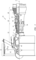
- FIG. 1 schematically illustrates a gas turbine engine 20 disclosed as a two-spool turbo fan that generally incorporates a fan section 22, a compressor section 24, a combustor section 26 and a turbine section 28.
- the fan section 22 drives air along a bypass flowpath while the compressor section 24 drives air along a core gas flowpath (see arrow C) for compression and communication into the combustor section 26 then expansion through the turbine section 28.
- a turbofan depicted as a turbofan in the disclosed non-limiting embodiment, it should be understood that the concepts described herein are not limited to use with turbofans as the teachings may be applied to other types of turbine engine architecture such as turbojets, turboshafts, three-spool turbofans, land-based turbine engines, and others.
- the engine 20 generally includes a low spool 30 and a high spool 32 mounted for rotation about an engine axis A via several bearing structures 38 and relative to a static engine case 36.
- the low spool 30 generally includes an inner shaft 40 that interconnects a fan 42 of the fan section 22, a low pressure compressor 44 (LPC) of the compressor section 24 and a low pressure turbine 46 (LPT) of the turbine section 28.
- the inner shaft 40 drives the fan 42 directly, or, through a geared architecture 48 to drive the fan 42 at a lower speed than the low spool 30.
- An exemplary reduction transmission may be an epicyclic transmission, namely a planetary or star gear system.
- the gas turbine engine 20 is a high-bypass geared aircraft engine.
- the gas turbine engine 20 bypass ratio is greater than about six (6:1).
- the geared architecture 48 can include an epicyclic gear train, such as a planetary gear system or other gear system.
- the example epicyclic gear train has a gear reduction ratio of greater than about 2.3:1, and in another example is greater than about 2.5:1.
- the geared turbofan enables operation of the low spool 30 at higher speeds that can increase the operational efficiency of the LPC 44 and LPT 46 and render increased pressure in a fewer number of stages.
- a pressure ratio associated with the LPT 46 is pressure measured prior to the inlet of the LPT 46 as related to the pressure at the outlet of the LPT 46 prior to an exhaust nozzle of the gas turbine engine 20.
- the bypass ratio of the gas turbine engine 20 is greater than about ten (10:1); the fan diameter is significantly larger than the LPC 44; and the LPT 46 has a pressure ratio that is greater than about five (5:1). It should be understood; however, that the above parameters are only exemplary of one example of a geared architecture engine and that the present disclosure is applicable to other gas turbine engines including direct drive turbofans.
- a significant amount of thrust is provided by the bypass flow path (see arrow B) due to the high bypass ratio.
- the fan section 22 of the gas turbine engine 20 is designed for a particular flight condition - typically cruise at about 0.8 Mach and about 35,000 feet (10,668 meters). This flight condition, with the gas turbine engine 20 at its best fuel consumption, is also known as Thrust Specific Fuel consumption (TSFC).
- TSFC Thrust Specific Fuel consumption
- Fan Pressure Ratio is the pressure ratio across a blade of the fan section 22 without the use of a fan exit guide vane system.
- the low Fan Pressure Ratio according to one, non-limiting, example of the gas turbine engine 20 is less than 1.45: 1.
- Low Corrected Fan Tip Speed is the actual fan tip speed divided by an industry standard temperature correction of (T/518.7) 0.5 , where "T" represents the ambient temperature in degrees Rankine.
- the Low Corrected Fan Tip Speed according to one non-limiting example of the gas turbine engine 20 is less than about 1,150 feet per second (351 meters per second).
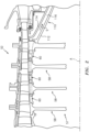
- the HPC 52 includes a rotor assembly 57, assembled from a plurality of successive HPC rotors 58 that alternate with HPC, ring-shaped, spacers 60 of the assembly arranged in an axially stacked configuration.
- the rotor stack may be assembled in a compressed tie-shaft configuration, with a central shaft (not shown) assembled concentrically within the rotor stack and secured with a nut (not shown), to generate a preload that compresses and retains the HPC rotor 58 with the HPC spacers 60 together as a spool.
- Friction at the interfaces between the HPC rotor 58 and the HPC spacers 60 may be solely responsible to prevent rotation between adjacent rotor hardware. That is, the rotors 58 and the spacers 60 generally rotate as one piece.
- each HPC rotor 58 generally includes a plurality of blades 62 circumferentially spaced around a rotor disk 64.
- the rotor disk 64 generally includes a hub 66, a rim 68, and a web 70 that spans between the hub and rim.
- Each blade 62 may include an attachment section or root 72, a platform 74 and an airfoil 76.
- static vane rings or vane stages may be spaced radially outward from respective spacers 60 to redirect the core airflow upon the adjacent, aft, blades 62.
- a spoke 78 may be generally carried between the rim 68 of the disk 64 and the root 72 of the blade 62.
- the spokes 78 may be circumferentially spaced from one another, thereby defining axial or semi-axial channels or slots 80 between adjacent spokes 78, and as part of a secondary air flowpath (see arrow S).
- the spokes 78 may be machined, cut with a wire EDM or other processes to provide the desired shape.
- An interface 82 of each spoke 78 generally defines the transient liquid phase bond and/or heat transition between the blades 62 and the rotor disk 64. That is, the spoke 78 contains the interface 82, and 'heat treat transition' is generally the transition between different heat treatments.
- the spokes 78 of the present disclosure provides a reduced area that is not subject to thermo-mechanical fatigue (TMF) seen in more traditional outer diameter walls (i.e. blade platforms and rotor rim) due to the relatively high temperature gradient.
- TMF thermo-mechanical fatigue
- the blade platforms 74 are exposed to the relatively hot core gas flowpath C; however, the radially inward spoked configuration acts to segment the hot outer diameter wall thus allowing for thermal growth between the platforms 74 and the rotor rim 68 of the rotor disk 64.
- the spoked configuration further provides the cooling channel 80 of the secondary flowpath S that thermally isolates the rotor rim 68 from the core gas flowpath C, thereby minimizing the thermal gradient between the rim 68 and the disk hub 66.
- each spacer 60 may have a similar architecture to adjacent portions of the HPC rotors 58. That is, each spacer 60 may include an outer ring 84 that spans axially between and seals to adjacent platforms 74 of the blades 62, an inner ring 86 spaced radially inward of the outer ring 84 and spanning axially between the adjacent rims 68 of the rotor disks 64, and a plurality of spokes 88 spaced circumferentially from one-another and each spanning radially between and generally engaged to the outer and inner rings 84, 86.
- a plurality of channels or slots 90 may each be defined circumferentially between respective and adjacent spokes 88 and radially between the outer and inner rings 84, 86.
- Each spoke 88 may have an interface 92 that generally bisects each spoke and provides the bond between the outer and inner rings 84, 86.
- the outer rings 84 may be manufactured of the same material as the blades 62, and the inner ring 86 may be manufactured of the same material as the rotor disks 64.
- the HPC spacers 60 may be manufactured of a single material but subjected to the different heat treatments that transition within the spokes 88.
- a relatively low temperature configuration will benefit from usage of a single material such that the spokes 88 facilitate a weight reduction.
- low-temperature bi-metal designs may further benefit from dissimilar materials for weight reduction where, for example, low density materials may be utilized when load carrying capability is less of a concern.
- the channels 80, 90 that flank the respective spokes 78, 88 may receive airflow from an upstream, inlet, HPC airflow supply ring 94 that may be a spacer similar to spacer 60.
- the supply ring 94 includes opposite outer and inner surfaces 96, 98 that may both be substantially cylindrical.
- a plurality of circumferentially spaced flow ducts 100 are in and defined by the supply ring 94 and may be ramped.
- Each duct 100 may include an inlet 102 generally defined by the outer surface 96 and an outlet 104 in direct fluid communication with respective channels 80 of the adjacent HPC rotor 58; which, in-turn, are in direct fluid communication with the channels 90 of the adjacent, downstream, spacer 60.
- the outer surface 96 may define in-part the core gas flowpath C, thus the inlet 102 may be in direct fluid communication with the core gas flowpath C at an upstream pressure stage location.
- the inlet ring 94 may draw cooling flow from the core gas flowpath C flow, secondary cooling flow, or combinations thereof.
- the cooling airflow may be communicated not only forward to aft toward the turbine section 28, but also aft to forward within the engine 20.
- the airflow may be drawn from adjacent static structure such as vanes to effect boundary flow turbulence as well as other flow conditions. That is, the HPC spacers 60 and the inlet ring 94 may facilitate through-flow for use in rim cooling, purge air for use down-stream in the compressor, and turbine or bearing compartment operation.
- FIG. 7 a second, non-limiting embodiment of an inlet ring is illustrated wherein like elements have like identifying numerals except with the addition of a prime symbol as a suffix.
- An inlet ring 94' of the second embodiment may have flow ducts 100' having an inlet 102' that is carried and defined by an inner surface 98' of the ring 94'.
- each inner ring 86 of the spacers 60 may include an upstream circumferential flange 106 and a downstream circumferential flange 108 that may be located radially inboard of, and thereby captured radially, by the respective, adjacent, rotor rims 68. That is, each inner ring 86 is engaged through the stacked configuration of the HPC 52.
- the stacked configuration is arranged to accommodate the relatively lower load capability alloys on the core gas flowpath C side of the rotor hardware, while maintaining the load carrying capability between the inner rings 86 and the rims 68 of the rotor disks 64 to transmit rotor torque and carry the centrifugal loads of the blades and segments 84.
- the alternating rotor rim 68 to inner ring 86 configuration may carry the rotor stack preload that may be upward of 150,000 pounds (68,039 kilograms) through the high load capability material of the rotor rim 68 to inner ring 86 interface, while permitting the usage of a high temperature resistant, yet lower load capability materials in the blades 62 and the sealing outer rings 84 of the spacers 60 that are exposed to the high temperature core gas flowpath C.
- the axial rotor stack load path may facilitate the use of a disk specific alloy to carry the stack load and allows for the high temperature resistant material to seal the rotor from the core gas flow path. That is, the inner diameter loading and outer diameter sealing permits a segmented airfoil and seal platform design that facilitates relatively inexpensive manufacture and high temperature capability.
- the HPC rotor assembly 57 further includes a rear shell 110 attached to and projecting in a downstream direction from the final, downstream, rotor 58 of the rotor assembly 57.
- the rear shell 110 is substantially concentric to axis A, generally conical in shape, and converges in a downstream direction.
- the shell 110 includes radially inner and outer walls 112, 114 with a passage 116 defined there-between.
- the passage 116 is generally part of the secondary air flowpath S, is generally annular, and is in direct fluid communication with the channels 80 in the adjacent, upstream, rotor 58.
- the shell 110 is constructed and arranged to rotate in unison with the rotors 58 and spacers 60.
- the rotor assembly 57 may further include a structure 118 that may be generally located radially inward of, and axially aligned to, the hubs 66 of the rotor disks 64 and the shell 110.
- the structure 118, or portion thereof: may generally rotate with the rotors 58, the spacers 60 and the shell 110; may extend axially; and, may be substantially concentric to axis A.
- the structure 118 may generally include the low spool 30 and a tie-shaft or bore tube 120 that may be part of the high spool 32.
- Another example of a tie-shaft 120 is disclosed in United States Patent 8,100,666, filed December 22, 2008 , assigned to Pratt & Whitney Canada Corporation of the United Technologies Corporation in Hartford, Connecticut.
- Selected forward rotor bores 122 and the rearward rotor bore 124 may generally be in fluid communication with one-another through a plurality of supply conduits 126 that may be defined, in-part, by the tie-shaft 120 of the structure 110. More specifically, the supply conduits 126 may extend through the hubs 66 of a selected number of rotor disks 64 and generally adjacent to the tie-shaft 120. Each supply conduit 126 at each respective rotor disk 64 may further be a plurality of circumferentially spaced conduits with the number of conduits and size generally dictated by the thermal gradient of the respective rotor disk.
- the secondary airflow first flows through the channels 80, 90 thus cooling and picking up heat from the adjacent rims 68 of the disks 64, roots 72 of the blades 62, and outer and inner rings 84, 86 of the spacers 60. From the rearward-most channels 80, the secondary airflow enters the passage 116 in the shell 110 and may pick up further heat from the surrounding walls 112, 114. In a warmed or heated state, the secondary airflow may then enter the rearward-most rotor bore 124, flow in an axial forward direction, through the conduit 126, and into the upstream rotor bore 122.
- This flow may continue in the forward direction and into successive rotor bores 122 through successive conduits 126 as dictated by the thermal needs of the rotor assembly 57.
- the air heats the rotor hubs 66 and may heat a portion of the webs 70 of the rotor disks 64, thereby reducing temperature gradients that reduces thermal stress.
- a reduction in thermal stress increases rim life, facilitates a reduction in bore size and rotor weight, and may realize achievement of a full life HPC rotor.
- Each inner ring 86 may further have at least one aperture 132 for flowing a portion of secondary airflow from at least one of the channels 90 of the spacers 60 and into the respective bores 122 for ventilation.
- This ventilating airflow (see arrow 134 in FIG. 8 ) may be minimal and may amount to one to two percent of the airflow flowing through the passage 116.
- the ventilating airflow 132 may be discharged from the bores 122 via the discharge conduit 128.
- a third embodiment of a rotor assembly wherein like elements to the first embodiment have the same identifying numerals except with the addition of a "double prime" suffix.
- the rotor assembly 57" of the third embodiment may not heat the rotor hubs 66" and instead, the secondary airflow may cool the shell 110" and may then flow directly to an LPT 46". That is, secondary airflow is routed through a passage 116" in the shell 110", then directly into an inlet 130" and into a discharge conduit 128".
- the inlet 130" may be in and communicate through a high spool 32" and the discharge conduit 128" may be defined radially between the low and high spools 30", 32".
- the secondary airflow once serving the HPC, may be routed to the HPT or elsewhere within the engine.
Landscapes
- Engineering & Computer Science (AREA)
- Mechanical Engineering (AREA)
- General Engineering & Computer Science (AREA)
- Physics & Mathematics (AREA)
- Thermal Sciences (AREA)
- Turbine Rotor Nozzle Sealing (AREA)
- Structures Of Non-Positive Displacement Pumps (AREA)
Claims (8)
- Ensemble rotor d'un moteur à turbine à gaz comprenant :un rotor HPC (58) destiné à tourner autour d'un axe de moteur (A) et comprenant un disque de rotor (64) et une pluralité de pales (62) comprenant chacune une plateforme (74) fixée au disque de rotor (64) avec un premier canal (80) défini radialement entre les plateformes (74) et le disque de rotor (64) ; etune coque arrière (110) fixée au rotor HPC final en aval (58) de l'ensemble rotor (57) et faisant saillie vers l'arrière à partir de celui-ci, la coque arrière (110) étant concentrique par rapport à l'axe de moteur (A), de forme conique, convergeant dans une direction aval et caractérisé en ce que la coque arrière (110) comprend une paroi radialement intérieure (112) et une paroi radialement extérieure (114) avec un passage (116) défini entre les parois intérieure (112) et extérieure (114) en communication fluidique avec le premier canal (80), dans lequel la coque (110) est construite et disposée pour tourner avec le rotor (58) adjacent ; et caractérisé en outre parune entretoise en forme d'anneau (60) disposée de manière adjacente et en amont du rotor HPC (58) avec un second canal (90) dans l'entretoise (60) étant en communication fluidique avec le premier canal (80) ;dans lequel le premier canal (80), le second canal et le passage (116) font partie d'un passage de flux d'air de refroidissement secondaire (3).
- Ensemble rotor selon la revendication 1, dans lequel le passage (80) est annulaire.
- Ensemble rotor selon la revendication 1 ou 2, dans lequel le rotor HPC (58) est un rotor en étoile comprenant une pluralité de premiers rayons (78) espacés circonférentiellement et généralement situés radialement entre les plateformes (74) et les disques de rotor (64), et le premier canal (80) est l'un d'une pluralité de premiers canaux (80), chaque premier canal (80) étant défini circonférentiellement entre des premiers rayons adjacents (78).
- Ensemble rotor selon la revendication 3, dans lequel l'entretoise (60) comprend des anneaux radialement intérieurs (84) et extérieurs (86) et une pluralité de seconds rayons (88) espacés circonférentiellement et se prolongeant radialement entre les anneaux intérieurs (84) et extérieurs (86), et le second canal (90) est l'un d'une pluralité de seconds canaux (90), chaque second canal (90) étant défini circonférentiellement entre des seconds rayons (88) adjacents.
- Ensemble rotor selon la revendication 4, dans lequel le disque de rotor (64) comprend un rebord (68) relié à la pluralité de premiers rayons (78) et définissant en partie la pluralité de premiers canaux (80).
- Ensemble rotor selon la revendication 5, dans lequel l'air de refroidissement circule à travers la pluralité de seconds canaux (90), puis à travers la pluralité de premiers canaux (80), puis dans le passage (116) pour refroidir la pluralité d'entretoises (60), la pluralité de plateformes (74), le rebord (68) et un moyeu (66) ou la coque (110).
- Ensemble rotor selon une quelconque revendication précédente comprenant également :
une structure (118) se prolongeant axialement et disposée radialement vers l'intérieur du disque de rotor (64) et de la coque (110), dans lequel la structure (118) définit au moins en partie un conduit d'alimentation (126) en communication fluidique entre le passage (116) et un alésage de rotor (122) défini au moins en partie entre des disques de rotor (64) adjacents. - Procédé de fonctionnement d'un système de passage de flux secondaire d'un moteur à turbine à gaz comprenant l'ensemble rotor selon la revendication 1, le procédé comprenant les étapes consistant à :faire circuler de l'air à travers le premier canal (80) défini au moins en partie entre la plateforme (74) d'une pale (62) de la pluralité de pales (62) et un rebord (68) du disque de rotor (64) pour refroidir au moins la plate-forme (74) et le rebord (68) ;faire circuler de l'air à travers le passage (116) en communication fluidique avec le premier canal (80) et défini par la coque arrière (110), la coque arrière (110) étant une coque annulaire (110) faisant saillie à l'arrière de la plate-forme (74) et du rebord (68) pour refroidir la coque (110) ; etfaire circuler de l'air à travers un conduit d'alimentation (126) en communication fluidique avec le passage (116) et dans au moins un alésage de rotor (122) défini entre des disques de rotor (64) adjacents pour chauffer au moins un moyeu (66) des disques de rotor (64) adjacents, contrôlant ainsi les gradients thermiques et réduisant la fatigue thermique du disque de rotor (64).
Applications Claiming Priority (1)
| Application Number | Priority Date | Filing Date | Title |
|---|---|---|---|
| US201462051547P | 2014-09-17 | 2014-09-17 |
Publications (2)
| Publication Number | Publication Date |
|---|---|
| EP3009596A1 EP3009596A1 (fr) | 2016-04-20 |
| EP3009596B1 true EP3009596B1 (fr) | 2025-03-05 |
Family
ID=54148443
Family Applications (1)
| Application Number | Title | Priority Date | Filing Date |
|---|---|---|---|
| EP15185751.3A Active EP3009596B1 (fr) | 2014-09-17 | 2015-09-17 | Système de passage de flux secondaire pour un ensemble rotor d'un moteur à turbine à gaz |
Country Status (2)
| Country | Link |
|---|---|
| US (1) | US10837288B2 (fr) |
| EP (1) | EP3009596B1 (fr) |
Families Citing this family (14)
| Publication number | Priority date | Publication date | Assignee | Title |
|---|---|---|---|---|
| US11377957B2 (en) | 2017-05-09 | 2022-07-05 | General Electric Company | Gas turbine engine with a diffuser cavity cooled compressor |
| US11060530B2 (en) * | 2018-01-04 | 2021-07-13 | General Electric Company | Compressor cooling in a gas turbine engine |
| US10746098B2 (en) | 2018-03-09 | 2020-08-18 | General Electric Company | Compressor rotor cooling apparatus |
| CN109113795A (zh) * | 2018-10-23 | 2019-01-01 | 中国船舶重工集团公司第七0三研究所 | 一种氦气轮机转子叶盘 |
| US11549374B2 (en) * | 2020-02-18 | 2023-01-10 | Raytheon Technologies Corporation | Gas turbine rotor component and method of manufacture |
| US11293294B2 (en) | 2020-05-22 | 2022-04-05 | Raytheon Technologies Corporation | Speed-controlled conditioning valve for high pressure compressor |
| US11525400B2 (en) * | 2020-07-08 | 2022-12-13 | General Electric Company | System for rotor assembly thermal gradient reduction |
| US11674396B2 (en) | 2021-07-30 | 2023-06-13 | General Electric Company | Cooling air delivery assembly |
| US11725531B2 (en) * | 2021-11-22 | 2023-08-15 | Raytheon Technologies Corporation | Bore compartment seals for gas turbine engines |
| US12320299B2 (en) | 2022-07-20 | 2025-06-03 | General Electric Company | Cooling air delivery system and methods thereof |
| US12044172B2 (en) | 2022-11-02 | 2024-07-23 | General Electric Company | Air guide for a gas turbine engine |
| CN116771431B (zh) * | 2023-06-19 | 2025-02-28 | 中国航发湖南动力机械研究所 | 一种转子内部冷却结构、方法及航空发动机内转子 |
| CN117869016B (zh) * | 2024-03-12 | 2024-05-17 | 中国航发四川燃气涡轮研究院 | 一种降低涡轮外环导热的冷却单元及其分析方法 |
| US20250389199A1 (en) * | 2024-06-20 | 2025-12-25 | Rtx Corporation | Tie Shaft Leakage Control |
Citations (3)
| Publication number | Priority date | Publication date | Assignee | Title |
|---|---|---|---|---|
| US2656147A (en) * | 1946-10-09 | 1953-10-20 | English Electric Co Ltd | Cooling of gas turbine rotors |
| JPS5847199A (ja) * | 1981-09-14 | 1983-03-18 | Hitachi Ltd | 軸流圧縮機 |
| US20130108413A1 (en) * | 2011-10-28 | 2013-05-02 | Gabriel L. Suciu | Secondary flow arrangement for slotted rotor |
Family Cites Families (28)
| Publication number | Priority date | Publication date | Assignee | Title |
|---|---|---|---|---|
| BE485338A (fr) * | 1948-10-15 | |||
| US3709631A (en) | 1971-03-18 | 1973-01-09 | Caterpillar Tractor Co | Turbine blade seal arrangement |
| US3742706A (en) * | 1971-12-20 | 1973-07-03 | Gen Electric | Dual flow cooled turbine arrangement for gas turbine engines |
| US3844110A (en) | 1973-02-26 | 1974-10-29 | Gen Electric | Gas turbine engine internal lubricant sump venting and pressurization system |
| DE2620762C2 (de) | 1976-05-11 | 1977-11-17 | Motoren- und Turbinen-Union München GmbH, 8000 München | Spaltdichtung für Strömungsmaschinen, insbesondere Gasturbinenstrahltriebwerke |
| GB2108628B (en) | 1981-10-28 | 1985-04-03 | Rolls Royce | Means for reducing stress in clamped assemblies |
| DE3428892A1 (de) | 1984-08-04 | 1986-02-13 | MTU Motoren- und Turbinen-Union München GmbH, 8000 München | Schaufel- und dichtspaltoptimierungseinrichtung fuer verdichter von gasturbinentriebwerken, insbesondere gasturbinenstrahltriebwerken |
| DE3606597C1 (de) * | 1986-02-28 | 1987-02-19 | Mtu Muenchen Gmbh | Schaufel- und Dichtspaltoptimierungseinrichtung fuer Verdichter von Gasturbinentriebwerken |
| US5340274A (en) | 1991-11-19 | 1994-08-23 | General Electric Company | Integrated steam/air cooling system for gas turbines |
| GB9606963D0 (en) | 1996-04-02 | 1996-06-05 | Rolls Royce Plc | A root attachment for a turbomachine blade |
| US6393829B2 (en) * | 1996-11-29 | 2002-05-28 | Hitachi, Ltd. | Coolant recovery type gas turbine |
| FR2782539B1 (fr) * | 1998-08-20 | 2000-10-06 | Snecma | Turbomachine comportant un dispositif de fourniture de gaz pressurise |
| JP3475838B2 (ja) | 1999-02-23 | 2003-12-10 | 株式会社日立製作所 | タービンロータ及びタービンロータのタービン動翼冷却方法 |
| US6234746B1 (en) | 1999-08-04 | 2001-05-22 | General Electric Co. | Apparatus and methods for cooling rotary components in a turbine |
| JP3518447B2 (ja) | 1999-11-05 | 2004-04-12 | 株式会社日立製作所 | ガスタービン,ガスタービン装置およびガスタービン動翼の冷媒回収方法 |
| DE19962244A1 (de) | 1999-12-22 | 2001-06-28 | Rolls Royce Deutschland | Kühlluft-Führungssystem im Hochdruck-Turbinenabschnitt eines Gasturbinen Triebwerkes |
| US6585482B1 (en) | 2000-06-20 | 2003-07-01 | General Electric Co. | Methods and apparatus for delivering cooling air within gas turbines |
| US7520718B2 (en) | 2005-07-18 | 2009-04-21 | Siemens Energy, Inc. | Seal and locking plate for turbine rotor assembly between turbine blade and turbine vane |
| US9133720B2 (en) | 2007-12-28 | 2015-09-15 | United Technologies Corporation | Integrally bladed rotor with slotted outer rim |
| GB0818047D0 (en) | 2008-10-03 | 2008-11-05 | Rolls Royce Plc | Turbine cooling system |
| US8287242B2 (en) | 2008-11-17 | 2012-10-16 | United Technologies Corporation | Turbine engine rotor hub |
| US8100666B2 (en) | 2008-12-22 | 2012-01-24 | Pratt & Whitney Canada Corp. | Rotor mounting system for gas turbine engine |
| US7993102B2 (en) | 2009-01-09 | 2011-08-09 | General Electric Company | Rotor cooling circuit |
| US8677763B2 (en) | 2009-03-10 | 2014-03-25 | General Electric Company | Method and apparatus for gas turbine engine temperature management |
| US8376689B2 (en) | 2010-04-14 | 2013-02-19 | General Electric Company | Turbine engine spacer |
| US9145771B2 (en) | 2010-07-28 | 2015-09-29 | United Technologies Corporation | Rotor assembly disk spacer for a gas turbine engine |
| GB201015028D0 (en) | 2010-09-10 | 2010-10-20 | Rolls Royce Plc | Gas turbine engine |
| EP2586971B1 (fr) | 2011-10-28 | 2019-06-12 | United Technologies Corporation | Joints d'étanchéité, rotor, axe et procédé d'orientation des flux de force lors de l'assemblage du rotor |
-
2015
- 2015-09-14 US US14/853,392 patent/US10837288B2/en active Active
- 2015-09-17 EP EP15185751.3A patent/EP3009596B1/fr active Active
Patent Citations (3)
| Publication number | Priority date | Publication date | Assignee | Title |
|---|---|---|---|---|
| US2656147A (en) * | 1946-10-09 | 1953-10-20 | English Electric Co Ltd | Cooling of gas turbine rotors |
| JPS5847199A (ja) * | 1981-09-14 | 1983-03-18 | Hitachi Ltd | 軸流圧縮機 |
| US20130108413A1 (en) * | 2011-10-28 | 2013-05-02 | Gabriel L. Suciu | Secondary flow arrangement for slotted rotor |
Also Published As
| Publication number | Publication date |
|---|---|
| EP3009596A1 (fr) | 2016-04-20 |
| US10837288B2 (en) | 2020-11-17 |
| US20160076381A1 (en) | 2016-03-17 |
Similar Documents
| Publication | Publication Date | Title |
|---|---|---|
| EP3009596B1 (fr) | Système de passage de flux secondaire pour un ensemble rotor d'un moteur à turbine à gaz | |
| US10760423B2 (en) | Spoked rotor for a gas turbine engine | |
| US8784062B2 (en) | Asymmetrically slotted rotor for a gas turbine engine | |
| EP3090163B1 (fr) | Gestion thermique de tambour de compresseur | |
| US8961132B2 (en) | Secondary flow arrangement for slotted rotor | |
| EP3594452B1 (fr) | Joint segmenté pour un moteur à turbine à gaz | |
| US8944762B2 (en) | Spoked spacer for a gas turbine engine | |
| EP2907978B1 (fr) | Cadre de turbine intermédiaire de moteur ayant un flux réfrigérant distributif | |
| US10082034B2 (en) | Rotor and gas turbine engine including same | |
| US20190368421A1 (en) | Gas turbine with rotating duct | |
| EP3875733B1 (fr) | Ensemble d'aubes pour moteur à turbine à gaz | |
| EP2586968B1 (fr) | Agencement d'écoulement secondaire pour rotor rainuré | |
| US10934845B2 (en) | Dual cooling airflow to blades | |
| EP3045681B1 (fr) | Moteur à turbine à gaz avec corps haute température et système de refroidissement associé | |
| US11668202B2 (en) | Airfoil core inlets in a rotating vane | |
| EP2586970B1 (fr) | Espaceur de disque échelé pour un moteur à turbine à gaz | |
| US12320299B2 (en) | Cooling air delivery system and methods thereof | |
| EP2957722B1 (fr) | Rotor pour un moteur à turbine à gaz | |
| EP3054091B1 (fr) | Moteur à turbine à gaz présentant une section avec une zone thermiquement isolée | |
| US11346558B2 (en) | Fuel injector | |
| US9869183B2 (en) | Thermal barrier coating inside cooling channels | |
| EP3392472B1 (fr) | Section de compresseur pour un moteur à turbine à gaz, moteur à turbine à gaz et procédé de fonctionnement d'une section de compresseur dans un moteur à turbine à gaz, associés |
Legal Events
| Date | Code | Title | Description |
|---|---|---|---|
| PUAI | Public reference made under article 153(3) epc to a published international application that has entered the european phase |
Free format text: ORIGINAL CODE: 0009012 |
|
| AK | Designated contracting states |
Kind code of ref document: A1 Designated state(s): AL AT BE BG CH CY CZ DE DK EE ES FI FR GB GR HR HU IE IS IT LI LT LU LV MC MK MT NL NO PL PT RO RS SE SI SK SM TR |
|
| AX | Request for extension of the european patent |
Extension state: BA ME |
|
| RAP1 | Party data changed (applicant data changed or rights of an application transferred) |
Owner name: UNITED TECHNOLOGIES CORPORATION |
|
| 17P | Request for examination filed |
Effective date: 20161020 |
|
| RBV | Designated contracting states (corrected) |
Designated state(s): AL AT BE BG CH CY CZ DE DK EE ES FI FR GB GR HR HU IE IS IT LI LT LU LV MC MK MT NL NO PL PT RO RS SE SI SK SM TR |
|
| STAA | Information on the status of an ep patent application or granted ep patent |
Free format text: STATUS: EXAMINATION IS IN PROGRESS |
|
| 17Q | First examination report despatched |
Effective date: 20190411 |
|
| RAP1 | Party data changed (applicant data changed or rights of an application transferred) |
Owner name: RAYTHEON TECHNOLOGIES CORPORATION |
|
| APBK | Appeal reference recorded |
Free format text: ORIGINAL CODE: EPIDOSNREFNE |
|
| APBN | Date of receipt of notice of appeal recorded |
Free format text: ORIGINAL CODE: EPIDOSNNOA2E |
|
| APBR | Date of receipt of statement of grounds of appeal recorded |
Free format text: ORIGINAL CODE: EPIDOSNNOA3E |
|
| APAF | Appeal reference modified |
Free format text: ORIGINAL CODE: EPIDOSCREFNE |
|
| APBX | Invitation to file observations in appeal sent |
Free format text: ORIGINAL CODE: EPIDOSNOBA2E |
|
| APBT | Appeal procedure closed |
Free format text: ORIGINAL CODE: EPIDOSNNOA9E |
|
| RAP3 | Party data changed (applicant data changed or rights of an application transferred) |
Owner name: RTX CORPORATION |
|
| APBV | Interlocutory revision of appeal recorded |
Free format text: ORIGINAL CODE: EPIDOSNIRAPE |
|
| GRAP | Despatch of communication of intention to grant a patent |
Free format text: ORIGINAL CODE: EPIDOSNIGR1 |
|
| STAA | Information on the status of an ep patent application or granted ep patent |
Free format text: STATUS: GRANT OF PATENT IS INTENDED |
|
| INTG | Intention to grant announced |
Effective date: 20240926 |
|
| GRAS | Grant fee paid |
Free format text: ORIGINAL CODE: EPIDOSNIGR3 |
|
| GRAA | (expected) grant |
Free format text: ORIGINAL CODE: 0009210 |
|
| STAA | Information on the status of an ep patent application or granted ep patent |
Free format text: STATUS: THE PATENT HAS BEEN GRANTED |
|
| AK | Designated contracting states |
Kind code of ref document: B1 Designated state(s): AL AT BE BG CH CY CZ DE DK EE ES FI FR GB GR HR HU IE IS IT LI LT LU LV MC MK MT NL NO PL PT RO RS SE SI SK SM TR |
|
| REG | Reference to a national code |
Ref country code: GB Ref legal event code: FG4D |
|
| REG | Reference to a national code |
Ref country code: CH Ref legal event code: EP |
|
| REG | Reference to a national code |
Ref country code: IE Ref legal event code: FG4D |
|
| REG | Reference to a national code |
Ref country code: DE Ref legal event code: R096 Ref document number: 602015091146 Country of ref document: DE |
|
| PG25 | Lapsed in a contracting state [announced via postgrant information from national office to epo] |
Ref country code: RS Free format text: LAPSE BECAUSE OF FAILURE TO SUBMIT A TRANSLATION OF THE DESCRIPTION OR TO PAY THE FEE WITHIN THE PRESCRIBED TIME-LIMIT Effective date: 20250605 |
|
| PG25 | Lapsed in a contracting state [announced via postgrant information from national office to epo] |
Ref country code: FI Free format text: LAPSE BECAUSE OF FAILURE TO SUBMIT A TRANSLATION OF THE DESCRIPTION OR TO PAY THE FEE WITHIN THE PRESCRIBED TIME-LIMIT Effective date: 20250305 |
|
| REG | Reference to a national code |
Ref country code: NL Ref legal event code: MP Effective date: 20250305 |
|
| PG25 | Lapsed in a contracting state [announced via postgrant information from national office to epo] |
Ref country code: ES Free format text: LAPSE BECAUSE OF FAILURE TO SUBMIT A TRANSLATION OF THE DESCRIPTION OR TO PAY THE FEE WITHIN THE PRESCRIBED TIME-LIMIT Effective date: 20250305 |
|
| REG | Reference to a national code |
Ref country code: LT Ref legal event code: MG9D |
|
| PG25 | Lapsed in a contracting state [announced via postgrant information from national office to epo] |
Ref country code: NO Free format text: LAPSE BECAUSE OF FAILURE TO SUBMIT A TRANSLATION OF THE DESCRIPTION OR TO PAY THE FEE WITHIN THE PRESCRIBED TIME-LIMIT Effective date: 20250605 |
|
| PG25 | Lapsed in a contracting state [announced via postgrant information from national office to epo] |
Ref country code: HR Free format text: LAPSE BECAUSE OF FAILURE TO SUBMIT A TRANSLATION OF THE DESCRIPTION OR TO PAY THE FEE WITHIN THE PRESCRIBED TIME-LIMIT Effective date: 20250305 |
|
| PG25 | Lapsed in a contracting state [announced via postgrant information from national office to epo] |
Ref country code: LV Free format text: LAPSE BECAUSE OF FAILURE TO SUBMIT A TRANSLATION OF THE DESCRIPTION OR TO PAY THE FEE WITHIN THE PRESCRIBED TIME-LIMIT Effective date: 20250305 |
|
| PG25 | Lapsed in a contracting state [announced via postgrant information from national office to epo] |
Ref country code: BG Free format text: LAPSE BECAUSE OF FAILURE TO SUBMIT A TRANSLATION OF THE DESCRIPTION OR TO PAY THE FEE WITHIN THE PRESCRIBED TIME-LIMIT Effective date: 20250305 Ref country code: GR Free format text: LAPSE BECAUSE OF FAILURE TO SUBMIT A TRANSLATION OF THE DESCRIPTION OR TO PAY THE FEE WITHIN THE PRESCRIBED TIME-LIMIT Effective date: 20250606 |
|
| REG | Reference to a national code |
Ref country code: AT Ref legal event code: MK05 Ref document number: 1773092 Country of ref document: AT Kind code of ref document: T Effective date: 20250305 |
|
| PG25 | Lapsed in a contracting state [announced via postgrant information from national office to epo] |
Ref country code: NL Free format text: LAPSE BECAUSE OF FAILURE TO SUBMIT A TRANSLATION OF THE DESCRIPTION OR TO PAY THE FEE WITHIN THE PRESCRIBED TIME-LIMIT Effective date: 20250305 |
|
| PG25 | Lapsed in a contracting state [announced via postgrant information from national office to epo] |
Ref country code: SE Free format text: LAPSE BECAUSE OF FAILURE TO SUBMIT A TRANSLATION OF THE DESCRIPTION OR TO PAY THE FEE WITHIN THE PRESCRIBED TIME-LIMIT Effective date: 20250305 |
|
| PG25 | Lapsed in a contracting state [announced via postgrant information from national office to epo] |
Ref country code: SM Free format text: LAPSE BECAUSE OF FAILURE TO SUBMIT A TRANSLATION OF THE DESCRIPTION OR TO PAY THE FEE WITHIN THE PRESCRIBED TIME-LIMIT Effective date: 20250305 |
|
| PG25 | Lapsed in a contracting state [announced via postgrant information from national office to epo] |
Ref country code: PT Free format text: LAPSE BECAUSE OF FAILURE TO SUBMIT A TRANSLATION OF THE DESCRIPTION OR TO PAY THE FEE WITHIN THE PRESCRIBED TIME-LIMIT Effective date: 20250707 |
|
| PGFP | Annual fee paid to national office [announced via postgrant information from national office to epo] |
Ref country code: DE Payment date: 20250820 Year of fee payment: 11 |
|
| PG25 | Lapsed in a contracting state [announced via postgrant information from national office to epo] |
Ref country code: IT Free format text: LAPSE BECAUSE OF FAILURE TO SUBMIT A TRANSLATION OF THE DESCRIPTION OR TO PAY THE FEE WITHIN THE PRESCRIBED TIME-LIMIT Effective date: 20250305 Ref country code: PL Free format text: LAPSE BECAUSE OF FAILURE TO SUBMIT A TRANSLATION OF THE DESCRIPTION OR TO PAY THE FEE WITHIN THE PRESCRIBED TIME-LIMIT Effective date: 20250305 |
|
| PGFP | Annual fee paid to national office [announced via postgrant information from national office to epo] |
Ref country code: GB Payment date: 20250822 Year of fee payment: 11 |
|
| PG25 | Lapsed in a contracting state [announced via postgrant information from national office to epo] |
Ref country code: AT Free format text: LAPSE BECAUSE OF FAILURE TO SUBMIT A TRANSLATION OF THE DESCRIPTION OR TO PAY THE FEE WITHIN THE PRESCRIBED TIME-LIMIT Effective date: 20250305 |
|
| PGFP | Annual fee paid to national office [announced via postgrant information from national office to epo] |
Ref country code: FR Payment date: 20250820 Year of fee payment: 11 |
|
| PG25 | Lapsed in a contracting state [announced via postgrant information from national office to epo] |
Ref country code: CZ Free format text: LAPSE BECAUSE OF FAILURE TO SUBMIT A TRANSLATION OF THE DESCRIPTION OR TO PAY THE FEE WITHIN THE PRESCRIBED TIME-LIMIT Effective date: 20250305 Ref country code: EE Free format text: LAPSE BECAUSE OF FAILURE TO SUBMIT A TRANSLATION OF THE DESCRIPTION OR TO PAY THE FEE WITHIN THE PRESCRIBED TIME-LIMIT Effective date: 20250305 |
|
| PG25 | Lapsed in a contracting state [announced via postgrant information from national office to epo] |
Ref country code: RO Free format text: LAPSE BECAUSE OF FAILURE TO SUBMIT A TRANSLATION OF THE DESCRIPTION OR TO PAY THE FEE WITHIN THE PRESCRIBED TIME-LIMIT Effective date: 20250305 |
|
| PG25 | Lapsed in a contracting state [announced via postgrant information from national office to epo] |
Ref country code: SK Free format text: LAPSE BECAUSE OF FAILURE TO SUBMIT A TRANSLATION OF THE DESCRIPTION OR TO PAY THE FEE WITHIN THE PRESCRIBED TIME-LIMIT Effective date: 20250305 |
|
| PG25 | Lapsed in a contracting state [announced via postgrant information from national office to epo] |
Ref country code: IS Free format text: LAPSE BECAUSE OF FAILURE TO SUBMIT A TRANSLATION OF THE DESCRIPTION OR TO PAY THE FEE WITHIN THE PRESCRIBED TIME-LIMIT Effective date: 20250705 |
|
| REG | Reference to a national code |
Ref country code: DE Ref legal event code: R097 Ref document number: 602015091146 Country of ref document: DE |
|
| PLBE | No opposition filed within time limit |
Free format text: ORIGINAL CODE: 0009261 |
|
| STAA | Information on the status of an ep patent application or granted ep patent |
Free format text: STATUS: NO OPPOSITION FILED WITHIN TIME LIMIT |
|
| PG25 | Lapsed in a contracting state [announced via postgrant information from national office to epo] |
Ref country code: DK Free format text: LAPSE BECAUSE OF FAILURE TO SUBMIT A TRANSLATION OF THE DESCRIPTION OR TO PAY THE FEE WITHIN THE PRESCRIBED TIME-LIMIT Effective date: 20250305 |
|
| REG | Reference to a national code |
Ref country code: CH Ref legal event code: L10 Free format text: ST27 STATUS EVENT CODE: U-0-0-L10-L00 (AS PROVIDED BY THE NATIONAL OFFICE) Effective date: 20260114 |
|
| 26N | No opposition filed |
Effective date: 20251208 |