EP3009656A1 - Soupape d'injection de fluide pour un moteur à combustion interne et procédé pour le faire fonctionner - Google Patents
Soupape d'injection de fluide pour un moteur à combustion interne et procédé pour le faire fonctionner Download PDFInfo
- Publication number
- EP3009656A1 EP3009656A1 EP14189025.1A EP14189025A EP3009656A1 EP 3009656 A1 EP3009656 A1 EP 3009656A1 EP 14189025 A EP14189025 A EP 14189025A EP 3009656 A1 EP3009656 A1 EP 3009656A1
- Authority
- EP
- European Patent Office
- Prior art keywords
- armature
- fluid injection
- injection valve
- pole piece
- valve
- Prior art date
- Legal status (The legal status is an assumption and is not a legal conclusion. Google has not performed a legal analysis and makes no representation as to the accuracy of the status listed.)
- Withdrawn
Links
Images


Classifications
-
- F—MECHANICAL ENGINEERING; LIGHTING; HEATING; WEAPONS; BLASTING
- F02—COMBUSTION ENGINES; HOT-GAS OR COMBUSTION-PRODUCT ENGINE PLANTS
- F02M—SUPPLYING COMBUSTION ENGINES IN GENERAL WITH COMBUSTIBLE MIXTURES OR CONSTITUENTS THEREOF
- F02M51/00—Fuel-injection apparatus characterised by being operated electrically
- F02M51/06—Injectors peculiar thereto with means directly operating the valve needle
- F02M51/061—Injectors peculiar thereto with means directly operating the valve needle using electromagnetic operating means
- F02M51/0625—Injectors peculiar thereto with means directly operating the valve needle using electromagnetic operating means characterised by arrangement of mobile armatures
- F02M51/0664—Injectors peculiar thereto with means directly operating the valve needle using electromagnetic operating means characterised by arrangement of mobile armatures having a cylindrically or partly cylindrically shaped armature, e.g. entering the winding; having a plate-shaped or undulated armature entering the winding
- F02M51/0685—Injectors peculiar thereto with means directly operating the valve needle using electromagnetic operating means characterised by arrangement of mobile armatures having a cylindrically or partly cylindrically shaped armature, e.g. entering the winding; having a plate-shaped or undulated armature entering the winding the armature and the valve being allowed to move relatively to each other or not being attached to each other
-
- F—MECHANICAL ENGINEERING; LIGHTING; HEATING; WEAPONS; BLASTING
- F02—COMBUSTION ENGINES; HOT-GAS OR COMBUSTION-PRODUCT ENGINE PLANTS
- F02M—SUPPLYING COMBUSTION ENGINES IN GENERAL WITH COMBUSTIBLE MIXTURES OR CONSTITUENTS THEREOF
- F02M51/00—Fuel-injection apparatus characterised by being operated electrically
- F02M51/06—Injectors peculiar thereto with means directly operating the valve needle
- F02M51/061—Injectors peculiar thereto with means directly operating the valve needle using electromagnetic operating means
- F02M51/0625—Injectors peculiar thereto with means directly operating the valve needle using electromagnetic operating means characterised by arrangement of mobile armatures
- F02M51/0664—Injectors peculiar thereto with means directly operating the valve needle using electromagnetic operating means characterised by arrangement of mobile armatures having a cylindrically or partly cylindrically shaped armature, e.g. entering the winding; having a plate-shaped or undulated armature entering the winding
- F02M51/0671—Injectors peculiar thereto with means directly operating the valve needle using electromagnetic operating means characterised by arrangement of mobile armatures having a cylindrically or partly cylindrically shaped armature, e.g. entering the winding; having a plate-shaped or undulated armature entering the winding the armature having an elongated valve body attached thereto
-
- F—MECHANICAL ENGINEERING; LIGHTING; HEATING; WEAPONS; BLASTING
- F02—COMBUSTION ENGINES; HOT-GAS OR COMBUSTION-PRODUCT ENGINE PLANTS
- F02M—SUPPLYING COMBUSTION ENGINES IN GENERAL WITH COMBUSTIBLE MIXTURES OR CONSTITUENTS THEREOF
- F02M63/00—Other fuel-injection apparatus having pertinent characteristics not provided for in groups F02M39/00 - F02M57/00 or F02M67/00; Details, component parts, or accessories of fuel-injection apparatus, not provided for in, or of interest apart from, the apparatus of groups F02M39/00 - F02M61/00 or F02M67/00; Combination of fuel pump with other devices, e.g. lubricating oil pump
- F02M63/0012—Valves
- F02M63/0014—Valves characterised by the valve actuating means
- F02M63/0015—Valves characterised by the valve actuating means electrical, e.g. using solenoid
- F02M63/0017—Valves characterised by the valve actuating means electrical, e.g. using solenoid using electromagnetic operating means
- F02M63/0021—Valves characterised by the valve actuating means electrical, e.g. using solenoid using electromagnetic operating means characterised by the arrangement of mobile armatures
- F02M63/0022—Valves characterised by the valve actuating means electrical, e.g. using solenoid using electromagnetic operating means characterised by the arrangement of mobile armatures the armature and the valve being allowed to move relatively to each other
-
- H—ELECTRICITY
- H01—ELECTRIC ELEMENTS
- H01F—MAGNETS; INDUCTANCES; TRANSFORMERS; SELECTION OF MATERIALS FOR THEIR MAGNETIC PROPERTIES
- H01F7/00—Magnets
- H01F7/06—Electromagnets; Actuators including electromagnets
- H01F7/08—Electromagnets; Actuators including electromagnets with armatures
- H01F7/16—Rectilinearly-movable armatures
- H01F7/1607—Armatures entering the winding
-
- F—MECHANICAL ENGINEERING; LIGHTING; HEATING; WEAPONS; BLASTING
- F02—COMBUSTION ENGINES; HOT-GAS OR COMBUSTION-PRODUCT ENGINE PLANTS
- F02M—SUPPLYING COMBUSTION ENGINES IN GENERAL WITH COMBUSTIBLE MIXTURES OR CONSTITUENTS THEREOF
- F02M2200/00—Details of fuel-injection apparatus, not otherwise provided for
- F02M2200/70—Linkage between actuator and actuated element, e.g. between piezoelectric actuator and needle valve or pump plunger
- F02M2200/701—Linkage between actuator and actuated element, e.g. between piezoelectric actuator and needle valve or pump plunger mechanical
- F02M2200/702—Linkage between actuator and actuated element, e.g. between piezoelectric actuator and needle valve or pump plunger mechanical with actuator and actuated element moving in different directions, e.g. in opposite directions
Definitions
- the invention relates to a fluid injection valve for a combustion engine and to a method for operating the same.
- Injection valves also called injectors
- injectors are in widespread use, in particular for combustion engines where they may be arranged in order to dose a fluid into an intake manifold of the combustion engine or directly into a combustion chamber of a cylinder of the combustion engine.
- an injector has tough performance requirements to enable injection of accurate quantities of fluid and to fulfill pollution restrictions during operation of the injector and a corresponding combustion engine.
- Two main requirements are the ability to open fast at high pressures, for example higher than 200 bar in case of gasoline injectors, and to enable fast closing times, for example less than 500 microseconds in order to have a low flow and low actuation time.
- Such requirements also concern hydraulic valves like solenoid actuated valves, for example.
- a solenoid injector the mentioned requirements can be fulfilled using high magnetic forces to enable fast opening of a valve needle of the injector.
- the magnetic force is generated by a coil which induces a movement of an armature which impacts on the valve needle and hence causes a movement of the valve needle.
- high magnetic forces are needed to overcome high hydraulic pressures of a fluid inside the injector, for example.
- One object of the invention is to create a fluid injection valve for a combustion engine which enables a reliable and secure functioning with particular high energy efficiency.
- a fluid injection valve for a combustion engine comprises a valve body, a pole piece, a coil, a valve needle, a first armature and a second armature.
- the fluid injection valve is in particular a fuel injector of the combustion engine.
- the valve body has a longitudinal axis and comprises a wall - in particular a circumferential side wall - which forms a recess that enables a streaming fluid to pass through the fluid injection valve during operation.
- the pole piece has a first axial end and a second axial end on opposite sides of the pole piece along the longitudinal axis. The pole piece is positionally fix relative to the valve body.
- the first armature faces the first axial end and the second armature faces the second axial end of the pole piece with respect to the longitudinal axis.
- the first armature and the second armature are arranged axially movably in the recess and are axially displaceable towards the pole piece by a magnetic force induced by the coil to generate a first mechanical force and a second mechanical force, respectively, to axially move the valve needle along the longitudinal axis.
- axial displacement of the first armature in a first axial direction towards the pole piece effects the first mechanical force
- axial displacement of the second armature in a second axial direction towards the pole piece effects the second mechanical force.
- the fluid injection valve comprises a leverage mechanism which is arranged between the pole piece and the first armature with respect to the longitudinal axis to transfer a mechanical force from the first armature to the valve needle for generating the first mechanical force acting on the valve needle during the operation of the fluid injection valve.
- the leverage mechanism has in particular a mechanical advantage so that the first mechanical force is larger than said mechanical force which is exerted on the leverage mechanism by the first armature.
- Such a configuration of the fluid injection valve describes a simple and reliable possibility to increase a mechanical force acting on the valve needle during an operation of the fluid injection valve or an injector comprising the fluid injection valve.
- the magnetic force generated by one single magnetic circuit of the fluid injection valve is efficiently transferred into mechanical force acting on the valve needle due to coaction of the first and the second armature and, in particular, the leverage mechanism.
- the described fluid injection valve has a reliable and secure function in particular when a high magnetic force is required from one single magnetic circuit. Due to the leverage mechanism there is no need for a second solenoid or a second magnetic circuit and a difficult design of the injector, for example. Hence, product cost can be reduced and the fluid injection valve enables a competitive arrangement of an injector which is simple in design and which exhibits an improved axial movement of the valve needle compared to an injector which comprises one armature and no leverage mechanism.
- the leverage mechanism commutates the mechanical force generated by the first armature and the second armature.
- the leverage mechanism interacts mechanically with the first armature and with the valve needle so that the first mechanical force on the valve needle which is generated by axial displacement of the first armature towards the pole piece in the first axial direction and the second mechanical force on the valve needle which is generated by axial displacement of the second armature towards the pole piece in the second axial direction, opposite to the first axial direction, are both directed in the same one of the first and second axial directions, i.e. the first and second mechanical forces are either both directed in the first axial direction or in the second axial direction.
- the pole piece and at least one of the first armature and the second armature comprise penetrating openings respectively through which the valve needle extends.
- This embodiment of the invention describes one possible configuration of the fluid injection valve and enables a symmetrical arrangement of the mentioned components along the longitudinal axis, for example.
- the pole piece, the first armature, the second armature and the valve needle are rotation-symmetrically constructed which is advantageous for manufacturing reasons and which realizes a simple arrangement of the fluid injection valve.
- the first armature generates the first force when the valve needle is in first axial positions and the second armature generates the second force when the needle is in second axial positions.
- the first positions are axially offset relative to the second positions.
- the first positions and the second positions axially overlap at least partially.
- the first positions are a subregion of the second positions or vice versa.
- This embodiment of the invention indicates that there the valve needle is axially displaceable between different regions in which only the first armature acts on the valve needle, only the second armature acts on the valve needle or both armatures act on the valve needle.
- the regions depend on the configuration of the corresponding armatures and on a possible lift which is realized by a predetermined distance of the respective armature to the pole piece for example. Hence, different movement characteristics for different needle positions of the valve needle along the longitudinal axis can be realized, for example.
- the valve needle may experience a particularly large mechanical force acting on it.
- only one armature may drive further movement of the valve needle at the end of the opening transient which prevents an overshoot of the valve needle or at least reduces an impact of the valve needle to the valve body, for example.
- using such a configuration of the fluid injection valve enables a fast opening of the injector and a reduced movement of the valve needle at an end of the opening transient.
- the valve needle comprises an edge - in particular a step - that interacts with the leverage mechanism during the operation of the fluid injection valve.
- the leverage mechanism is operable to engage in a form-fit connection with the edge.
- the form-fit engagement is in particular releasable to disengage the first armature from the valve needle, so that only the second armature coupled to to the valve needle in at least some of the second positions.
- This configuration of the fluid injection valve describes one possible arrangement of the valve needle which interacts with the leverage mechanism.
- the edge of the valve needle is formed in the area of the leverage mechanism between the first armature and the pole piece with respect to the longitudinal axis. Hence, the edge realizes a simple embodiment of a contact point where the leverage mechanism impacts on the valve needle.
- the leverage mechanism comprises a first lever and a second lever.
- the first lever and the second lever are preferably positioned vis-à-vis with respect to the longitudinal axis in the recess.
- the first armature is coupled to the leverage mechanism and the two separate levers which are basically ashlar-formed. Furthermore, there is a contact region between the first armature and the first and second lever as well as between the edge of the valve needle and the first and second lever, for example.
- the contact regions are axially displaceable relative to the pole piece and the valve body while a fulcrum of each lever is preferably positionally fix relative to the pole piece and the valve body.
- a method for operation of an fluid injection valve in accordance with one of the preceding embodiments of the first aspect comprises a step of providing a fluid injection valve in accordance with one of the preceding embodiments and acting of a first force on the valve needle generated by the first armature within a first time period.
- the method further comprises acting of a second force on the valve needle generated by the second armature within a second time period wherein the first time period and the second time period at least partially temporarily overlap with each other.
- the first and second time periods may correspond to the above described first and second positions of the valve needle, respectively.
- This aspect of the invention indicates a possible enhanced movement of the valve needle as a process of time analogously to the above mentioned spatial overlap of the first and second positions.
- the first force represents the mechanical force effected by the first armature and the leverage mechanism on the valve needle and the second force represents the mechanical force on the valve needle effected by the second armature.
- An overlap of the first and the second time periods enables a fast opening of the fluid injection valve while a non-overlapping portion, for example of the second time period, may reduce impact of the valve needle to the valve body. Therefore, the first time period within the first armature generates the first force acting on the valve needle is temporally shorter than the second time period. But both time periods start from a beginning of an opening transient of the injector. Later on, only the second armature acts on the valve needle due to the temporally longer second time period and the second force generated there within.
- Figure 1 shows an exemplary embodiment of a fluid injection valve 1 which comprises a valve body 3, a pole piece 9, a coil 11, a valve needle 13, a first armature 15, a second armature 17 and a leverage mechanism 19.
- the valve body 3 has a longitudinal axis L and comprises a circumferential side wall 5 which forms a recess 7 that enables a streaming fluid to pass through the fluid injection valve 1 during an operation.
- the pole piece 9 is fixed to the wall 5 of the valve body 3 inside the recess 7.
- the first armature 15, the pole piece 9 and the second armature 17 are axially subsequently arranged along the longitudinal axis L inside the recess 7 of the valve body 3. Furthermore, the first armature 15 and the second armature 17 are arranged axially movably in the recess 7 along the longitudinal axis L relative to the pole piece 9. They are displaceable towards the pole piece 9 by a magnetic force induced by the coil 11 so that the first armature 15 moves in a first axial direction D1 towards the pole piece 9 and the second armature 17 moves in a second axial direction D2 towards the pole piece 9, opposite to the first axial direction D1 (cf. Fig. 2 ). In this embodiment the coil 11 surrounds the valve body 3 and the components inside the recess 7.
- the first armature 15 comprises a penetrating opening 23, the pole piece 9 comprises a penetrating opening 21 and the second armature 17 comprises a penetrating opening 25 in which the valve needle 13 is arranged to prevent a fluid flow in a closed position or otherwise to enable it.
- the first armature 15 faces a first axial end 10 of the pole piece 9 whereas the second armature 17 faces a second axial end 12 of the pole piece 9.
- the first armature 15 and the second armature 17 are arranged on opposite sides of the pole piece 9 along the longitudinal axis L.
- the fluid injection valve 1 comprises the leverage mechanism 19 which is arranged between the first armature 15 and the pole piece 9 with respect to the longitudinal axis L.
- the leverage mechanism 19 is configured to reverse a direction of a mechanical force generated by the first armature 15.
- the leverage mechanism 19 may be arranged between the second armature 17 and the pole piece 9 with respect to the longitudinal axis L to reverse a direction of a mechanical force generated by the second armature 17.
- the coil 11 is energized and the first armature 15 and the second armature 17 are attracted by the pole piece 9 by means of the magnetic force induced by the coil 11.
- the armatures 15, 17 move in opposite directions towards each other as described above. They are configured to generate a first mechanical force F1 and a second mechanical force F2, respectively.
- the first and second forces F1, F2 act on the valve needle 13 to axially move the valve needle 13 along the longitudinal axis L. Because of the leverage mechanism 19 a direction of the mechanical force which is effected by the first armature 15 is inverted by means of the leverage mechanism 19 to generate the first mechanical force F1.
- the mechanical force which is effected by the first armature 15 on the leverage mechanism 19 and the first mechanical force F1 on the valve needle 13 are directed in opposite axial directions. Therefore, both the first armature 15 and the second armature 17 generate a mechanical force - the first and second forces F1, F2 - on the valve needle 13 in the same axial direction.
- the second force F2 on the valve needle 13 is directly transferred to the valve needle 13 by the second armature 17, i.e. without directional change.
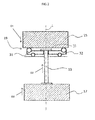
- Figure 2 schematically illustrates the functioning of the fluid injection valve 1 and shows the first armature 15, the second armature 17, the leverage mechanism 19 and the valve needle 13.
- the pole piece 9 and the penetrating openings 23, 25 of the first armature 15 and the second armature 17 are omitted to simplify the explanation of the working principle of the fluid injection valve 1.
- the leverage mechanism 19 comprises a first lever 31 and a second lever 32. Due to this simple arrangement using two separate levers 31, 32 a commutation of the force direction generated by movement of the first armature 15 can easily been realized.
- straight arrows indicate the first and second axial directions D1 and D2 in which the appropriate components move for generating the first and second mechanical forces F1 and F2.
- the leverage mechanism 19 comprises at least four contact regions, two to the first armature 15 and two to the pole piece 9 which is not illustrated in this figure 2 but only roughly indicated by the horizontal line directly below the leverage mechnism.
- the contact regions of the leverage mechanism 19 with the pole piece 9 - in particular with the first axial end 10 of the pole piece 9 - represent fulcrums of the first and second levers 31, 32, respectively. Due to the movement of the first armature 15 and its contact regions - one corresponding to each lever 31, 32 - the respective lever 31 and 31 are tilted with respect to the longitudinal axis L. Specifically, they may be rotated around the contact regions of the first and second lever 31, 32 to the pole piece 9 which act like fulcrums.
- the first and the second lever 31, 32 further contact an edge 33 of the valve needle 13 - in particular on a side of the respective lever 31, 32 opposite of the respective contact region with the first armature 15 with respect to the fulcrum - and hence generate the first force F1 on the valve needle 13 which is directed in the second axial direction D2 to promote a movement of the valve needle 13 in the second axial direction due D2 to the induced tilt by the movement of the first armature 15 in the first axial direction D1.
- the second armature 17 for example directly contacts a further edge or a nose of the valve needle 13 and hence generates a movement of the valve needle 13 in the same direction as the one of the second armature 17 namely the second direction.
- the contact regions between the two levers 31, 32 and the first armature 15 and the pole piece 9 can be punctual realized but also line- or area-shaped in dependence of the leverage mechanism needed for application.
- Such a configuration of the fluid injection valve 1 describes a simple and reliable possibility to increase a mechanical force acting on the valve needle 13 during an operation of the fluid injection valve 1.
- the magnetic force generated by one single magnetic circuit of the fluid injection valve 1 comprising at least one valve body 3, one pole piece 9, one coil 11 and two armatures 15, 17 is efficiently transferred into mechanical force acting on the valve needle 13 due to coaction of the first and the second armature 15, 17 and the leverage mechanism 19.
- the leverage mechanism 19 commutates the movements of the first and the second armature 15, 17 which originally move towards each other because of its arrangement on opposite sides of the pole piece 9 along the longitudinal axis L.
- the described fluid injection valve 1 enables a reliable and secure function in particular when high magnetic force is required from one magnetic circuit. Due to the leverage mechanism 19, there is no need for a second solenoid or a second magnetic circuit and a difficult design of the injector, for example. Hence, product cost can be reduced and the fluid injection valve 1 enables a competitive arrangement of an injector which is simple in design and which exhibits an improved axial movement of the valve needle 13 compared to an injector which comprises one armature and no leverage mechanism 19.
- FIG 3 a further exemplary embodiment of the leverage mechanism 19 is illustrated in a perspective view.
- the first lever 31 and the second lever 32 are formed as two separate substantially ashlar-formed components which act on the edge 33 of the valve needle 13.
- the valve needle 13 is symmetrically arranged along the longitudinal axis L - i.e. in particular a needle axis of the valve needle 13 being coaxial to the longitudinal axis L - and the pole piece 9 comprises a recess 14 in which the first lever 31 and the second lever 32 are arranged.
- the first armature 15 comprises a disc like shape whereas the pole piece 9 substantially comprises a cylindrical shape with the above mentioned recess 14.
- the edge 33 of the valve needle 13 overlaps with the fulcrums of the levers 31, 32 in top view along the longitudinal axis, while the contact regions of the levers 31, 32 with the first armature 15 are positioned in an outer radial end region of each lever 31, 32. In this way, a large mechanical advantage is achieved so that the first mechanical force F1 on the valve needle 13 is particularly large.
- a comparatively large axial displacement of the first armature 15 is translated into a much smaller axial displacement of the valve needle 13 at the end of which the levers 31, 32 may disengage from the form-fit connection with the edge 33 and the valve needle is further displaced in the second axial direction D2 by means of direct mechanical interaction with the second armature 17 (not shown in Fig. 3 ).
- Such a configuration is particularly advantageous for displacing the valve needle 13 away from a closing position, where it is in sealing contact with a valve seat of the fluid injection valve 1, against high fluid pressures. In this case, a large force is needed at the beginning of the opening transient to overcome the hydraulic force of the fluid pressure. Once there is a small gap between the valve needle 13 and the valve seat, the hydraulic force decreases and only a smaller force is needed to displace the valve needle 13 further away from the valve seat.
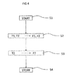
- Figure 4 illustrates a simple exemplary flowchart of a method for operation of the fluid injection valve 1 or a corresponding injector.
- a first step S1 the fluid injection valve 1 and the injector starts its operation by means of starting of an injection event, for example.
- a second step S2 an opening transient of the fluid injection valve 1 is initiated wherein a generated first force F1 and second force F2 act on the valve needle 13 within a first time period T1 and a second time period T2, respectively.
- the second time period T2 is longer than the first time period T1 while both time periods preferably start simultaneously and hence the second force F2 acts for a longer time on the valve needle than the first force F1.
- the first force F1 and the second force F2 are generated by the movements of the first armature 15 and the second armature 17, respectively, which movements are induced by energizing the coil 11 and generating a magnetic force attracting the armatures 15, 17 towards the pole piece 9.
- the first force F1 represents the mechanical force effected by the first armature 15 via the leverage mechanism 19
- the second force F2 represents the mechanical force given by the second armature 17. Therefore, due to the leverage mechanism 19 described above, the magnetically induced movements of the armatures 15 and 17 are translated into forces which are directed in the same axial direction so that the absolute values of the first and second forces F1, F2 add up to move and/or accelerate the valve needle 13 along the longitudinal axis L.
- an overlap of the first time period T1 and the second time period T2 of the respective armature 15, 17 enables a fast opening of the fluid injection valve 1 and the corresponding injector and reduces an impact of the valve needle 13 to the valve body 3, for example.
- a third step S3 only the second time period T2 is still active - i.e. for example only the second armature 17 is still moving towards the pole piece 9 while the first armature 15 may already be in form-fit connection with the pole piece 9 or a separate stopper - and hence only the second force F2 generated by the second armature 17 is still acting on the valve needle 13. For this reason, the resulting movement of the valve needle 13 is induced only by the second armature 17 for example to achieve the complete opening position of the valve needle 13 and the fluid injection valve 1.
- Such a method for operating the fluid injection valve 1 prevents an impact or at least makes a contribution to reduce an impact of the valve needle 13 and/or the second armature 17 on adjacent components of the injector like the valve body 3, for instances.
- Step S4 represents an ending of the method for operating the fluid injection valve 1 and may correspond to deactivation of the coil 11 for closing the fluid injection valve 1 to end the injection event, for example.
- the method for operation of the fluid injection valve 1 describes two differently driven movements of the valve needle 13 which at least partially overlap in time. This allows for an enhanced movement of the valve needle 13 which is advantageous to rapidly move the valve needle 13 from its closed position even against high pressures of the fluid inside the injector, for example. This further allows for an axially movement of the valve needle 13 for different needle lift along the longitudinal axis L, for example, and enables a reliable and secure functioning of a fuel injector for a combustion engine with an improved energy efficiency because there is one coil 11 energized which generates two movements of two separate armatures 15 and 17 respectively.
- the described fluid injection valve 1 and/or method for operation it is also possible to operate two valves simultaneously and differently.
- the movement of the first armature 15 may act on another valve than the movement of the second armature 17. This advantageously allows for different movements of two valves concerning an absolute value of needle lift, for example, and enables an injection of different quantities of fluid amongst others.
- the two armatures 15 and 17 exhibit different magnetic gaps 16, 18 to the pole piece 9 and each armature 15, 17 can be submitted to a different spring load.
Landscapes
- Engineering & Computer Science (AREA)
- Physics & Mathematics (AREA)
- Electromagnetism (AREA)
- Chemical & Material Sciences (AREA)
- Combustion & Propulsion (AREA)
- Mechanical Engineering (AREA)
- General Engineering & Computer Science (AREA)
- Power Engineering (AREA)
- Fuel-Injection Apparatus (AREA)
Priority Applications (1)
| Application Number | Priority Date | Filing Date | Title |
|---|---|---|---|
| EP14189025.1A EP3009656A1 (fr) | 2014-10-15 | 2014-10-15 | Soupape d'injection de fluide pour un moteur à combustion interne et procédé pour le faire fonctionner |
Applications Claiming Priority (1)
| Application Number | Priority Date | Filing Date | Title |
|---|---|---|---|
| EP14189025.1A EP3009656A1 (fr) | 2014-10-15 | 2014-10-15 | Soupape d'injection de fluide pour un moteur à combustion interne et procédé pour le faire fonctionner |
Publications (1)
| Publication Number | Publication Date |
|---|---|
| EP3009656A1 true EP3009656A1 (fr) | 2016-04-20 |
Family
ID=51690973
Family Applications (1)
| Application Number | Title | Priority Date | Filing Date |
|---|---|---|---|
| EP14189025.1A Withdrawn EP3009656A1 (fr) | 2014-10-15 | 2014-10-15 | Soupape d'injection de fluide pour un moteur à combustion interne et procédé pour le faire fonctionner |
Country Status (1)
| Country | Link |
|---|---|
| EP (1) | EP3009656A1 (fr) |
Citations (5)
| Publication number | Priority date | Publication date | Assignee | Title |
|---|---|---|---|---|
| EP0188673A2 (fr) * | 1985-01-19 | 1986-07-30 | WABCO Westinghouse Fahrzeugbremsen GmbH | Soupape à voies multiples commandée par électro-aimant |
| EP0404357A2 (fr) * | 1989-06-21 | 1990-12-27 | General Motors Corporation | Soupape injectrice |
| EP2236807A1 (fr) * | 2009-03-23 | 2010-10-06 | Continental Automotive GmbH | Injecteur de fluide |
| DE102011076956A1 (de) * | 2011-06-06 | 2012-12-06 | Robert Bosch Gmbh | Kraftstoffinjektor |
| DE102012218763A1 (de) * | 2012-10-15 | 2014-04-17 | Continental Automotive Gmbh | Mechanische Übersetzungseinrichtung sowie Hebeleinrichtung für einen Kraftstoffinjektor |
-
2014
- 2014-10-15 EP EP14189025.1A patent/EP3009656A1/fr not_active Withdrawn
Patent Citations (5)
| Publication number | Priority date | Publication date | Assignee | Title |
|---|---|---|---|---|
| EP0188673A2 (fr) * | 1985-01-19 | 1986-07-30 | WABCO Westinghouse Fahrzeugbremsen GmbH | Soupape à voies multiples commandée par électro-aimant |
| EP0404357A2 (fr) * | 1989-06-21 | 1990-12-27 | General Motors Corporation | Soupape injectrice |
| EP2236807A1 (fr) * | 2009-03-23 | 2010-10-06 | Continental Automotive GmbH | Injecteur de fluide |
| DE102011076956A1 (de) * | 2011-06-06 | 2012-12-06 | Robert Bosch Gmbh | Kraftstoffinjektor |
| DE102012218763A1 (de) * | 2012-10-15 | 2014-04-17 | Continental Automotive Gmbh | Mechanische Übersetzungseinrichtung sowie Hebeleinrichtung für einen Kraftstoffinjektor |
Similar Documents
| Publication | Publication Date | Title |
|---|---|---|
| JP5487451B2 (ja) | 内燃エンジンバルブトレイン切替え装置 | |
| EP2535552A1 (fr) | Ensemble de soupape pour soupape dýinjection et soupape dýinjection | |
| EP2622203B1 (fr) | Ensemble soupape pour une soupape d'injection et soupape d'injection | |
| EP2796703A1 (fr) | Ensemble de soupape pour soupape d'injection et soupape d'injection | |
| CN110100089B9 (zh) | 用于配给流体的阀 | |
| JP6655723B2 (ja) | 燃料噴射弁 | |
| US9382885B2 (en) | Fuel injection valve for an internal combustion engine | |
| US5903070A (en) | Electromagnetic actuator having a slender structure | |
| US8517334B2 (en) | Electromagnetic valve mechanism | |
| EP2597296B1 (fr) | Ensemble de soupape pour soupape d'injection et soupape d'injection | |
| EP2851551B1 (fr) | Soupape d'injection de fluide | |
| JP2013167194A (ja) | 燃料噴射弁 | |
| JP6613973B2 (ja) | 燃料噴射装置 | |
| CN105637213B (zh) | 阀 | |
| US9470194B2 (en) | Injector for injecting fuel into an internal combustion engine | |
| KR102139895B1 (ko) | 자기 링 요소를 갖는 분사 밸브 | |
| EP3009656A1 (fr) | Soupape d'injection de fluide pour un moteur à combustion interne et procédé pour le faire fonctionner | |
| JP2018135882A (ja) | 電磁切換弁および高圧燃料ポンプ | |
| EP2863042B1 (fr) | Soupape d'injection | |
| JP6913816B2 (ja) | 燃料噴射弁及びその組立方法 | |
| US9500169B2 (en) | Lever device and a fuel injection valve | |
| JP2010151002A (ja) | 電磁ソレノイド装置 | |
| EP2206940B1 (fr) | Actionneur de soupape | |
| JP2007023890A (ja) | 内燃機関の制御装置 | |
| KR20180082354A (ko) | 연료 분사 시스템용 솔레노이드 밸브 및 고압 연료 펌프 |
Legal Events
| Date | Code | Title | Description |
|---|---|---|---|
| PUAI | Public reference made under article 153(3) epc to a published international application that has entered the european phase |
Free format text: ORIGINAL CODE: 0009012 |
|
| AK | Designated contracting states |
Kind code of ref document: A1 Designated state(s): AL AT BE BG CH CY CZ DE DK EE ES FI FR GB GR HR HU IE IS IT LI LT LU LV MC MK MT NL NO PL PT RO RS SE SI SK SM TR |
|
| AX | Request for extension of the european patent |
Extension state: BA ME |
|
| 17P | Request for examination filed |
Effective date: 20161020 |
|
| RBV | Designated contracting states (corrected) |
Designated state(s): AL AT BE BG CH CY CZ DE DK EE ES FI FR GB GR HR HU IE IS IT LI LT LU LV MC MK MT NL NO PL PT RO RS SE SI SK SM TR |
|
| 17Q | First examination report despatched |
Effective date: 20180105 |
|
| GRAP | Despatch of communication of intention to grant a patent |
Free format text: ORIGINAL CODE: EPIDOSNIGR1 |
|
| INTG | Intention to grant announced |
Effective date: 20181129 |
|
| STAA | Information on the status of an ep patent application or granted ep patent |
Free format text: STATUS: THE APPLICATION IS DEEMED TO BE WITHDRAWN |
|
| 18D | Application deemed to be withdrawn |
Effective date: 20190410 |