EP3009671A1 - Éolienne verticale - Google Patents
Éolienne verticale Download PDFInfo
- Publication number
- EP3009671A1 EP3009671A1 EP14189369.3A EP14189369A EP3009671A1 EP 3009671 A1 EP3009671 A1 EP 3009671A1 EP 14189369 A EP14189369 A EP 14189369A EP 3009671 A1 EP3009671 A1 EP 3009671A1
- Authority
- EP
- European Patent Office
- Prior art keywords
- wind
- rotor
- upright members
- wind turbine
- vertical
- Prior art date
- Legal status (The legal status is an assumption and is not a legal conclusion. Google has not performed a legal analysis and makes no representation as to the accuracy of the status listed.)
- Ceased
Links
- 230000001419 dependent effect Effects 0.000 claims abstract description 7
- 238000004088 simulation Methods 0.000 description 17
- 229910052751 metal Inorganic materials 0.000 description 9
- 239000002184 metal Substances 0.000 description 9
- 239000013598 vector Substances 0.000 description 9
- 238000000034 method Methods 0.000 description 3
- 241000700608 Sagitta Species 0.000 description 2
- 238000010276 construction Methods 0.000 description 2
- 239000000463 material Substances 0.000 description 2
- 238000005096 rolling process Methods 0.000 description 2
- UJCHIZDEQZMODR-BYPYZUCNSA-N (2r)-2-acetamido-3-sulfanylpropanamide Chemical class CC(=O)N[C@@H](CS)C(N)=O UJCHIZDEQZMODR-BYPYZUCNSA-N 0.000 description 1
- 230000001133 acceleration Effects 0.000 description 1
- 229910052782 aluminium Inorganic materials 0.000 description 1
- XAGFODPZIPBFFR-UHFFFAOYSA-N aluminium Chemical compound [Al] XAGFODPZIPBFFR-UHFFFAOYSA-N 0.000 description 1
- 238000005452 bending Methods 0.000 description 1
- 230000000903 blocking effect Effects 0.000 description 1
- 239000003086 colorant Substances 0.000 description 1
- 239000002131 composite material Substances 0.000 description 1
- 230000006835 compression Effects 0.000 description 1
- 238000007906 compression Methods 0.000 description 1
- 230000008602 contraction Effects 0.000 description 1
- 230000003247 decreasing effect Effects 0.000 description 1
- 230000007547 defect Effects 0.000 description 1
- 238000006073 displacement reaction Methods 0.000 description 1
- 230000000694 effects Effects 0.000 description 1
- 230000002349 favourable effect Effects 0.000 description 1
- 238000004519 manufacturing process Methods 0.000 description 1
- 230000009467 reduction Effects 0.000 description 1
Images






Classifications
-
- F—MECHANICAL ENGINEERING; LIGHTING; HEATING; WEAPONS; BLASTING
- F03—MACHINES OR ENGINES FOR LIQUIDS; WIND, SPRING, OR WEIGHT MOTORS; PRODUCING MECHANICAL POWER OR A REACTIVE PROPULSIVE THRUST, NOT OTHERWISE PROVIDED FOR
- F03D—WIND MOTORS
- F03D7/00—Controlling wind motors
- F03D7/06—Controlling wind motors the wind motors having rotation axis substantially perpendicular to the air flow entering the rotor
-
- F—MECHANICAL ENGINEERING; LIGHTING; HEATING; WEAPONS; BLASTING
- F03—MACHINES OR ENGINES FOR LIQUIDS; WIND, SPRING, OR WEIGHT MOTORS; PRODUCING MECHANICAL POWER OR A REACTIVE PROPULSIVE THRUST, NOT OTHERWISE PROVIDED FOR
- F03D—WIND MOTORS
- F03D3/00—Wind motors with rotation axis substantially perpendicular to the air flow entering the rotor
- F03D3/005—Wind motors with rotation axis substantially perpendicular to the air flow entering the rotor the axis being vertical
-
- F—MECHANICAL ENGINEERING; LIGHTING; HEATING; WEAPONS; BLASTING
- F05—INDEXING SCHEMES RELATING TO ENGINES OR PUMPS IN VARIOUS SUBCLASSES OF CLASSES F01-F04
- F05B—INDEXING SCHEME RELATING TO WIND, SPRING, WEIGHT, INERTIA OR LIKE MOTORS, TO MACHINES OR ENGINES FOR LIQUIDS COVERED BY SUBCLASSES F03B, F03D AND F03G
- F05B2240/00—Components
- F05B2240/10—Stators
- F05B2240/12—Fluid guiding means, e.g. vanes
-
- F—MECHANICAL ENGINEERING; LIGHTING; HEATING; WEAPONS; BLASTING
- F05—INDEXING SCHEMES RELATING TO ENGINES OR PUMPS IN VARIOUS SUBCLASSES OF CLASSES F01-F04
- F05B—INDEXING SCHEME RELATING TO WIND, SPRING, WEIGHT, INERTIA OR LIKE MOTORS, TO MACHINES OR ENGINES FOR LIQUIDS COVERED BY SUBCLASSES F03B, F03D AND F03G
- F05B2240/00—Components
- F05B2240/10—Stators
- F05B2240/13—Stators to collect or cause flow towards or away from turbines
- F05B2240/133—Stators to collect or cause flow towards or away from turbines with a convergent-divergent guiding structure, e.g. a Venturi conduit
-
- F—MECHANICAL ENGINEERING; LIGHTING; HEATING; WEAPONS; BLASTING
- F05—INDEXING SCHEMES RELATING TO ENGINES OR PUMPS IN VARIOUS SUBCLASSES OF CLASSES F01-F04
- F05B—INDEXING SCHEME RELATING TO WIND, SPRING, WEIGHT, INERTIA OR LIKE MOTORS, TO MACHINES OR ENGINES FOR LIQUIDS COVERED BY SUBCLASSES F03B, F03D AND F03G
- F05B2240/00—Components
- F05B2240/20—Rotors
- F05B2240/21—Rotors for wind turbines
- F05B2240/211—Rotors for wind turbines with vertical axis
- F05B2240/212—Rotors for wind turbines with vertical axis of the Darrieus type
-
- F—MECHANICAL ENGINEERING; LIGHTING; HEATING; WEAPONS; BLASTING
- F05—INDEXING SCHEMES RELATING TO ENGINES OR PUMPS IN VARIOUS SUBCLASSES OF CLASSES F01-F04
- F05B—INDEXING SCHEME RELATING TO WIND, SPRING, WEIGHT, INERTIA OR LIKE MOTORS, TO MACHINES OR ENGINES FOR LIQUIDS COVERED BY SUBCLASSES F03B, F03D AND F03G
- F05B2250/00—Geometry
- F05B2250/20—Geometry three-dimensional
- F05B2250/23—Geometry three-dimensional prismatic
- F05B2250/231—Geometry three-dimensional prismatic cylindrical
-
- F—MECHANICAL ENGINEERING; LIGHTING; HEATING; WEAPONS; BLASTING
- F05—INDEXING SCHEMES RELATING TO ENGINES OR PUMPS IN VARIOUS SUBCLASSES OF CLASSES F01-F04
- F05B—INDEXING SCHEME RELATING TO WIND, SPRING, WEIGHT, INERTIA OR LIKE MOTORS, TO MACHINES OR ENGINES FOR LIQUIDS COVERED BY SUBCLASSES F03B, F03D AND F03G
- F05B2250/00—Geometry
- F05B2250/20—Geometry three-dimensional
- F05B2250/29—Geometry three-dimensional machined; miscellaneous
- F05B2250/291—Geometry three-dimensional machined; miscellaneous hollowed
-
- F—MECHANICAL ENGINEERING; LIGHTING; HEATING; WEAPONS; BLASTING
- F05—INDEXING SCHEMES RELATING TO ENGINES OR PUMPS IN VARIOUS SUBCLASSES OF CLASSES F01-F04
- F05B—INDEXING SCHEME RELATING TO WIND, SPRING, WEIGHT, INERTIA OR LIKE MOTORS, TO MACHINES OR ENGINES FOR LIQUIDS COVERED BY SUBCLASSES F03B, F03D AND F03G
- F05B2250/00—Geometry
- F05B2250/70—Shape
- F05B2250/71—Shape curved
- F05B2250/711—Shape curved convex
-
- F—MECHANICAL ENGINEERING; LIGHTING; HEATING; WEAPONS; BLASTING
- F05—INDEXING SCHEMES RELATING TO ENGINES OR PUMPS IN VARIOUS SUBCLASSES OF CLASSES F01-F04
- F05B—INDEXING SCHEME RELATING TO WIND, SPRING, WEIGHT, INERTIA OR LIKE MOTORS, TO MACHINES OR ENGINES FOR LIQUIDS COVERED BY SUBCLASSES F03B, F03D AND F03G
- F05B2270/00—Control
- F05B2270/30—Control parameters, e.g. input parameters
- F05B2270/32—Wind speeds
-
- F—MECHANICAL ENGINEERING; LIGHTING; HEATING; WEAPONS; BLASTING
- F05—INDEXING SCHEMES RELATING TO ENGINES OR PUMPS IN VARIOUS SUBCLASSES OF CLASSES F01-F04
- F05B—INDEXING SCHEME RELATING TO WIND, SPRING, WEIGHT, INERTIA OR LIKE MOTORS, TO MACHINES OR ENGINES FOR LIQUIDS COVERED BY SUBCLASSES F03B, F03D AND F03G
- F05B2270/00—Control
- F05B2270/30—Control parameters, e.g. input parameters
- F05B2270/321—Wind directions
-
- Y—GENERAL TAGGING OF NEW TECHNOLOGICAL DEVELOPMENTS; GENERAL TAGGING OF CROSS-SECTIONAL TECHNOLOGIES SPANNING OVER SEVERAL SECTIONS OF THE IPC; TECHNICAL SUBJECTS COVERED BY FORMER USPC CROSS-REFERENCE ART COLLECTIONS [XRACs] AND DIGESTS
- Y02—TECHNOLOGIES OR APPLICATIONS FOR MITIGATION OR ADAPTATION AGAINST CLIMATE CHANGE
- Y02E—REDUCTION OF GREENHOUSE GAS [GHG] EMISSIONS, RELATED TO ENERGY GENERATION, TRANSMISSION OR DISTRIBUTION
- Y02E10/00—Energy generation through renewable energy sources
- Y02E10/70—Wind energy
- Y02E10/74—Wind turbines with rotation axis perpendicular to the wind direction
Definitions
- the invention relates to the general field of vertical wind turbines. More in particular, the present invention relates to vertical wind turbines having a Darrieus-type rotor.
- Wind turbines of several types are known in the art.
- the most popular wind turbines nowadays are wind turbines with a horizontal axis, but there are also two types of wind turbines with a vertical axis, generally referred to as "Savonius"-type and “Darrieus”-type, but the working principles of both types are completely different.
- Darrieus-type rotors rotate by virtue of drag and lift forces
- Savonius-type rotors rotate by virtue of capturing wind in a concave surface moving in the wind direction, and diverting wind on a convex surface moving against the wind direction.
- Turbines having a rotor of the Darrieus-type are known for almost a century. Originally filed in France in 1925, and extended to the US in 1926, Mr. Darrieus discloses in US1835018A a wind turbine having three or four rotor blades held rigidly in position between two supporting disks or plates. The rotor blades have a shape which is nowadays referred to as an "airfoil". However, the efficiency of such a turbine is not very high.
- FIG. 7 of this publication shows a structure consisting of twelve outer blades each having an airfoil shape twice as large as those of the rotor blades, and oriented radially. According to the description typically ten to fifteen blades are used. The alleged purpose of the outer blades is to guide the wind falling upon counter acting rotor blades.
- the present invention provides a vertical wind turbine for converting mechanical energy of a wind into electrical energy, the wind turbine comprising: a rotor of the Darrieus-type, rotatably mounted around a vertical axis and having a plurality of rotor blades; a wind guidance assembly rotatably mounted with respect to said vertical axis and comprising exactly two upright members, the upright members being fixedly mounted to said assembly in such a way that the rotor is positioned at least partly between the two upright members, each upright member having a convex surface segment facing the rotor; means for orienting or rotating the wind guidance assembly dependent on the direction of the wind.
- the vertical wind turbine has a wind guidance assembly as described, because such upright members will bend the streamlines of the wind in a manner that will increase the torque exerted on the rotor, which results in a higher efficiency of the wind turbine.
- the wind guidance assembly has only two upright members, because such an assembly is easier to make as compared to for example an assembly having ten or twelve or fifteen blades.
- the wind guidance assembly can be optimally oriented for any wind direction.
- the concave surface segment of each of the upright members has a substantially constant curvature over at least half of its outer area, because such structures are easy to produce.
- the rotor blades are preferably rectilinear blades with an airfoil cross section, fixedly mounted to the rotor (thus not rotatable about their own axis), because this is easier to make and less prone to defects.
- the number of rotor blades is three or four.
- each of the upright members is a hollow three-dimensional body.
- the "backside" of the upright members i.e. the side which is facing away from the rotor, is closed by a flat or convex surface, because otherwise the wind may cause turbulences inside the concave space, which may cause vibrations (thus wear) and acoustical noise, but that is not absolutely necessary, and the backside may also be left open.
- the "bottom” and “top” are preferably also closed, but that is not absolutely necessary.
- the upright members are hollow bodies, because it will decrease the weight of the members, hence facilitate orienting of the wind guidance assembly, and facilitate easy mounting of the wind turbine, even heights of about 5 to 10 meters.
- Rigid hollow bodies can readily be made for example by using a metal framework on the inside, and a metal plate on the outside.
- a preferred material is aluminum, but other materials may also be used.
- both upright members have an identical shape.
- each of the upright members is a cylindrical shape.
- cylinders as the upright members because cylinders, e.g. metal cylinders, or plastic cylinders, or composite cylinders are readily available, and easy to mount.
- the cylinders are preferably mounted such that the axes of the two upright cylinders and the axis of the rotor are located in a same plane.
- each of the upright members have a planar surface segment facing away from the rotor.
- planar surfaces of both upright members are mounted substantially parallel.
- planar surfaces of both upright members can be oriented substantially parallel to the direction of the wind.
- a cross-section of the upright members in a horizontal plane is a closed circular segment, having a chord and an arc, the arc having a radius "R" in the range of 25% to 150% of the diameter "D" of the cylindrical space defined by the rotor blades.
- One particularly advantageous embodiments is one where the shape is in fact half of a cylinder, but the "backside" of which is closed by a flat plate, and whereby the diameter of the half cylinder is about 40% to about 60% of the diameter defined by the rotor blades, for example about 50%. According to simulations, such an embodiment provides an efficiency improvement of about 56%, despite the simple structure.
- chord length L in the range of about 70% to 140%, for example about 70% to 90% or about 110% to 140% of the diameter defined by the rotor blades, and a height H (also known as "sagitta") equal to 15% to 25% of the chord length L, for example about 20%. According to simulations, such embodiments may provide an efficiency improvement of about 29% to about 64% respectively.
- a cross-section of the upright members in a horizontal plane is a closed shape composed of a first linear segment, and a first arc segment having a first radius R1 and a second arc segment having a second radius R2.
- the means for orienting the wind guidance assembly comprises a sensor for measuring the direction of the wind, and a controller connected to the sensor for reading the measured direction, and a motor connected to said controller for rotating the wind guidance assembly for allowing passage of the wind between the two upright members.
- the controller is preferably adapted for orienting the wind guidance assembly such that the plane formed by the two axis of the upright members is substantially perpendicular to the direction of the wind.
- the vertical wind turbine further comprises a second sensor for measuring a speed of the wind
- the controller is further adapted for orienting the wind guidance assembly for restricting passage of the wind between the two upright members when the measured speed is above a predefined threshold.
- the rotor can be protected from turning too fast when the wind speed is too high, by orienting the wind guidance assembly in front of the rotor, so that the wind would blow primarily against one of the upright members, without creating the advantageous streamlines described above.
- the upright members are half-cylinders with a diameter of only half the diameter of the rotor, the power provided to the rotor can be reduced by 93%, thereby effectively protecting the rotor against damage.
- FIG. 1 shows an example of a vertical wind turbine 100 with a Darrieus-type rotor, known in the art.
- the rotor has three rotor blades 101.
- Each rotor blade is an elongated vertical profile having an airfoil in horizontal cross section.
- Many different airfoil profiles are known in the art, and are suitable for use in a wind turbine.
- a popular series is the NACA series, but other shapes may also be used.
- One of the main disadvantages of the wind turbine shown in FIG. 1 is that its power efficiency is not very high, which partly explains why these wind turbines are not very popular.
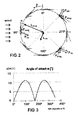
- FIG. 2 will be used to explain the basic working-principles of a Darrieus-type rotor.
- a rotor blade having an airfoil shape is shown at eight positions on a virtual circle. In each of these positions, two air velocity vectors are shown, one (shown horizontally) representing the absolute wind speed, a second (shown tangential to the circle) representing the relative speed of the rotor blade when moving on the circle at a given angular speed (in absence of wind), the sum vector representing the relative speed of the air with respect to the rotor blade when turning at a given angular speed in the presence of wind.
- the forces exerted by the air on the airfoil can be decomposed in two parts: a so called “drag force”, oriented in the direction of the velocity sum vector, and a so called “lift force” oriented perpendicular to the drag force.
- drag force oriented in the direction of the velocity sum vector
- lift force oriented perpendicular to the drag force.
- the drag force “Fdrag” shown in the position at 90° multiplied by the distance "Ldrag” represents a first torque trying to slow down the rotor.
- the lift force “Flift” multiplied by the distance “Llift” represents a second torque trying to accelerate the rotor.
- the combined torque is the difference between the second torque (due to the lift force) and the first torque (due to the drag force), which is the useful torque providing mechanical energy that will be converted into electrical energy, using a generator.
- the electrical part of wind turbines is well known in the art, no further explanation is deemed necessary.
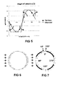
- FIG. 4 shows an example of the torque related to the drag force and the lift force, and the combined torque exerted upon each rotor blade, as it moves along the virtual circle, assuming the wind speed is 5.0 m/s, and the angular velocity of the rotor blades is 10.47 rad/s, and the diameter of the circle described by the rotor blades is 5.0 m.
- the present invention is not limited to wind turbines having a diameter of only 5.0 meter, and other values may also be used, for example any diameter in the range of 1.0 m to 10.0 m.
- the inventors further realized that the angle of attack (and torque) is already quite satisfactory around 90° (e.g. in the range of about 60° to about 120°) and around 270° (e.g. in the range of about 240° to about 300°), so it might not be required to change the direction of the wind at these locations. They further realized that if the wind would effectively have to enter the imaginary circle at about 10° as indicated, and would have to leave the circle again at about 350° as indicated, the wind would almost have "to stop and turn around", which is impossible without causing a lot of turbulences, which is highly undesirable.
- the two three-dimensional closed shapes have the form of two half-cylinders, which are to be positioned near azimuth angles 0° and 180°.
- the two upright elements 1803 of FIG. 18 may be mounted on a lower holder 1804 and an upper holder 1805, which are rotatable around the vertical axis 1802, but other holders, such as e.g. a circular disk or the like, could also be used. It is an advantage the upright members are fixedly mounted to the wind guidance assembly, so that by simply rotating the holders 1804, 1805 the position of the upright members 1803 can be oriented dependent on the direction of the wind.
- the wind turbine 1800 further comprises a rotor of the Darrieus type having a number of vertical rotor blades 1801, three in the example shown, but four would also be possible.
- the rotor blades 1801 having a cross section in a horizontal plane in the shape of an aerodynamic airfoil for creating drag and lift forces as explained in relation to FIG. 2 .
- the rotor and the wind guidance assembly are coaxially mounted around the same vertical axis 1802, but normally they do not rotate at the same speed. In fact, the wind guidance assembly is relatively stationary, and only rotates as the direction of the wind moves. Other details such as bearings etc. are conventional, and are omitted from the drawings.
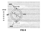
- FIG. 8 shows the effect of adding two upright members 1803 in the form of two half cylinders with a diameter d, which in this case is equal to D/2, D being the diameter of the imaginary circle defined by the rotor blades.
- d the diameter of the imaginary circle defined by the rotor blades.
- a disadvantage of this wind guidance assembly is that some turbulence is generated on the outer sides of the half-cylinders, and also behind the trailing edge of the half cylinders (on the right of the members in FIG. 8 ), which may create some acoustical noise. These turbulences do not, however, seem to negatively influence the efficiency of the turbine, since the air flow is not turbulent on or within the imaginary circle.
- the diameter d may be smaller or larger than 50% of D, for example in the range of 25% to 100% of D, for example about 60% of D, or about 70% of D, or about 80% of D, or about 90% of D.
- FIG. 9 shows the wind vector lines for another wind guidance assembly having two cylindrical upright elements 903 (shown in cross section), with a diameter "d" of about 25% of the diameter "D" of the imaginary circle of the rotor.
- the efficiency improvement is 23%, despite the very basic structure of merely two cylinders.
- the turbulence zone is located outside of the imaginary circle of the rotor blades, hence, although being undesirable from acoustical viewpoint, it has no impact on the power efficiency.
- the efficiency of the Darrieus wind turbine can be improved by 23% by simply placing two small cylinders on either side, albeit that they have to be repositioned when the direction of the wind changes.
- FIG. 10 schematically shows (in cross-sectional view) another embodiment of the present invention having a wind guidance assembly with two upright hollow shapes having a horizontal cross-section in the form of a circular segment, arranged at opposite sides of the rotor, along with a simulated vector-field of the wind.
- the circular segment consists of an arc segment and a linear segment.
- the arc segment is convex, and is facing the rotor.
- the linear segment is facing away from the rotor.
- wind guidance assembly of FIG. 10 has two symmetry planes, denoted by "S1" and "S2", both passing through the central vertical axis. The same symmetry planes are also present for other embodiments, but not shown.
- the chord length L of the cross section of the upright elements 1003 is about 70% of the diameter D of the virtual circle defined by the rotor blades, but other dimensions can also be used.
- L can be in the range of 50% to about 150% of D, for example about 50% to about 90% of D, or about 110% to about 140% of D.
- the height H also known as "sagitta"
- Such shapes are easy to produce, and they improve the power efficiency of the Darrieus rotor significantly, without causing a considerable amount of turbulence or noise, which is a major advantage of these embodiments.
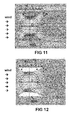
- FIG. 11 shows a variant of the embodiment of FIG. 10 , having substantially the same cross sectional shape, but a larger size.
- the ratio of the length L over the diameter D is about 140%, and the ratio of H over L is about 20%.
- the efficiency improvement by adding this structure to the Darrieus rotor is 64% for a wind speed of 5.0 m/s.
- the rotor-diameter was assumed to be 5.0 m. Larger structures have not been simulated, because such structures would become very bulky, especially when taking into account that they are typically mounted 5 to 10 meters or higher above the ground.
- FIG. 12 shows a variant of the embodiment of FIG. 11 , having substantially the same dimensions, but a more complicated shape.
- the leading edge of the shape was compressed, and the trailing edge of the shape was expanded.
- the cross section of these upright hollow members 1203 is a closed shape composed of a first linear segment, and a first arc segment having a first radius R1 and a second arc segment having a second radius R2.
- shape may be produced as a combination of a first metal plate having a first radius R1, and a second metal plate having a second radius R2 larger than R1, and a flat metal plate at the "back".
- the efficiency improvement offered by this structure is 67%, which is only marginally higher than that of FIG. 11 , while being more complicated to produce.
- This example shows that even though the structure of FIG. 11 is relatively simple (a mere circular segment), yet is close to optimal in view of performance improvement, and it may not be worth the effort to produce these more complicated structures.
- the former curve is substantially the same in the zone 0° to 180° on the one hand and 180° to 360° on the other hand, which may be explained by the symmetry of the structure and of the streamlines of the wind, but that the two partial curves are quite different for the latter curve, where apparently a small decrease of torque in the range of 0° to 180° is compensated by a small increase of torque in the range 180° to 360°, but the total result is substantially the same for both, as explained above.
- FIG. 17 shows the integrated torque over a complete revolution for the examples described above, and is also indicative for the power efficiency improvement of the wind turbine according to the present invention.
- the present invention is not limited to these specific examples, and other variants can easily be designed, e.g. by merely choosing different dimensions for d, L or H.
- FIG. 18 shows an exploded view of an embodiment of a vertical wind turbine 1800 with a wind guidance assembly according to the present invention, which is rotatable in dependence of the direction of the wind.
- the wind guidance assembly may have a passive means (such as an upright wing on top of the wind guidance assembly), or an active system comprising a sensor for measuring the wind direction, and a controller, and a motor, none of which are shown, but are well known in the art, and hence need not be further explained here.
- the wind guidance system may be self-orienting without a motor and without a wing on top. This may be achieved for example by embodiments like the one shown in FIG. 12 .
- the length of the arc with radius R2 is much longer than the length of the arc with radius R1, e.g. at least 3.0 times as long, e.g. at least 4.0 times as long.
- Such a control system active or passive would orient the wind guidance assembly such that the two upright members 1803 are positioned on the left and on the right of the rotor, as seen by the wind, or stated in other words, that the symmetry plane passing between said upright members is parallel to the direction of the wind.
- the height of the rotor (corresponding to the length of the rotor blades) shown in FIG. 18 is in the same order of magnitude as the diameter of the rotor, but may also be smaller or larger.
- the ratio of the height over the diameter may be any value in the range of 50% to 500%, preferably in the range of 50% to 250%, for example about 100% or about 150%.
- a Darrieus-rotor with three rotor blades 1801 is shown in top view in FIG. 19 , but in alternative embodiments, the rotor may have only two rotor blades, or four rotor blades.
- the rotor blades 1801 shown in FIG. 18 are straight over their entire length in the upright direction, but that is not absolutely required, and the blades may also have a curved portion, e.g. at their bottom side or at their top side, or they may be entirely curved. An example of such an embodiment is shown in FIG. 26 .
- the two upright members of the wind guidance assembly are two hollow three-dimensional bodies. In the example of FIG. 18 , these have the shape of a half cylinder, but other shapes may also be used, as discussed in relation to FIG 8 to FIG. 12 .
- the upright members 1803, 1003, 1103, 1203 are closed three-dimensional bodies, because the invention would also work if the "back" side of these upright members (i.e. the side facing away from the rotor) is at least partly left open.
- Such upright member could for example consist of a rolled metal plate.
- FIG. 20 shows in top view that the rotor blades 1801 define a virtual cylinder with a circular cross section, which virtual cylinder is located between the two upright members 1803 of the wind guidance assembly, at a relatively short distance therefrom, which can easily be determined by the skilled person, by trial and error.
- upright members with another cross-section may also be used, for example cylinders shown in FIG. 21 , or other circular segments defined by an arc segment and a chord segment, as shown in FIG. 23 or FIG. 24 .
- the diameter "d" of the outer cylinders or cylindrical segments may be increased or decreased relative to the diameter "D" of the rotor, as was already discussed before.
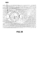
- FIG. 25 illustrates an additional optional feature of the present invention, whereby the wind turbine further comprises a second sensor for measuring the wind speed, and whereby the controller is further adapted for rotating the wind guidance assembly in front of the rotor in case the measured wind velocity is above a predefined threshold, for protecting the rotor and electrical circuitry etc. connected thereto.
- FIG. 25 shows simulated stream lines of the wind in such a case, for a wind speed of 5 m/s, although the threshold value may typically be e.g. at least 18 m/s, e.g. about 20 m/s or about 25 m/s. As can be seen from the simulation, a lot of turbulence is created in such a case, but the power of the rotor is effectively reduced by 93%.
Landscapes
- Engineering & Computer Science (AREA)
- Life Sciences & Earth Sciences (AREA)
- Sustainable Development (AREA)
- Sustainable Energy (AREA)
- Chemical & Material Sciences (AREA)
- Combustion & Propulsion (AREA)
- Mechanical Engineering (AREA)
- General Engineering & Computer Science (AREA)
- Wind Motors (AREA)
Priority Applications (1)
| Application Number | Priority Date | Filing Date | Title |
|---|---|---|---|
| EP14189369.3A EP3009671A1 (fr) | 2014-10-17 | 2014-10-17 | Éolienne verticale |
Applications Claiming Priority (1)
| Application Number | Priority Date | Filing Date | Title |
|---|---|---|---|
| EP14189369.3A EP3009671A1 (fr) | 2014-10-17 | 2014-10-17 | Éolienne verticale |
Publications (1)
| Publication Number | Publication Date |
|---|---|
| EP3009671A1 true EP3009671A1 (fr) | 2016-04-20 |
Family
ID=51753061
Family Applications (1)
| Application Number | Title | Priority Date | Filing Date |
|---|---|---|---|
| EP14189369.3A Ceased EP3009671A1 (fr) | 2014-10-17 | 2014-10-17 | Éolienne verticale |
Country Status (1)
| Country | Link |
|---|---|
| EP (1) | EP3009671A1 (fr) |
Cited By (1)
| Publication number | Priority date | Publication date | Assignee | Title |
|---|---|---|---|---|
| RU211743U1 (ru) * | 2021-05-24 | 2022-06-21 | Руслан Александрович Гросу | Вертикальный ветрогенератор с повышенной производительностью |
Citations (6)
| Publication number | Priority date | Publication date | Assignee | Title |
|---|---|---|---|---|
| US1835018A (en) | 1925-10-09 | 1931-12-08 | Leblanc Vickers Maurice Sa | Turbine having its rotating shaft transverse to the flow of the current |
| US5380149A (en) | 1990-05-31 | 1995-01-10 | Valsamidis; Michael | Wind turbine cross wind machine |
| EP1413748A1 (fr) * | 2002-10-22 | 2004-04-28 | Dixi Holding b.v. | Turbine eolienne a axe vertical avec systeme collecteur de vent |
| US20100034649A1 (en) * | 2006-06-27 | 2010-02-11 | Derek Alan Taylor | Device for enhancing the effectiveness of power conversion from wind and other fluids |
| US20110204632A1 (en) * | 2010-02-25 | 2011-08-25 | Skala James A | Synchronous Induced Wind Power Generation System |
| US20130294918A1 (en) * | 2010-11-05 | 2013-11-07 | OydroQuest | Transverse Flow Marine Turbine with Autonomous Stages |
-
2014
- 2014-10-17 EP EP14189369.3A patent/EP3009671A1/fr not_active Ceased
Patent Citations (6)
| Publication number | Priority date | Publication date | Assignee | Title |
|---|---|---|---|---|
| US1835018A (en) | 1925-10-09 | 1931-12-08 | Leblanc Vickers Maurice Sa | Turbine having its rotating shaft transverse to the flow of the current |
| US5380149A (en) | 1990-05-31 | 1995-01-10 | Valsamidis; Michael | Wind turbine cross wind machine |
| EP1413748A1 (fr) * | 2002-10-22 | 2004-04-28 | Dixi Holding b.v. | Turbine eolienne a axe vertical avec systeme collecteur de vent |
| US20100034649A1 (en) * | 2006-06-27 | 2010-02-11 | Derek Alan Taylor | Device for enhancing the effectiveness of power conversion from wind and other fluids |
| US20110204632A1 (en) * | 2010-02-25 | 2011-08-25 | Skala James A | Synchronous Induced Wind Power Generation System |
| US20130294918A1 (en) * | 2010-11-05 | 2013-11-07 | OydroQuest | Transverse Flow Marine Turbine with Autonomous Stages |
Cited By (1)
| Publication number | Priority date | Publication date | Assignee | Title |
|---|---|---|---|---|
| RU211743U1 (ru) * | 2021-05-24 | 2022-06-21 | Руслан Александрович Гросу | Вертикальный ветрогенератор с повышенной производительностью |
Similar Documents
| Publication | Publication Date | Title |
|---|---|---|
| US10669985B2 (en) | Fluid turbine systems | |
| US7347660B2 (en) | Cross-flow wind turbine | |
| US10634116B1 (en) | Wind turbine | |
| JP2010507036A (ja) | エネルギ獲得機械用の流れ偏向装置及び方法 | |
| US10400746B1 (en) | Wind turbine | |
| ES2338835B1 (es) | Dispositivo generador de fuerza motriz. | |
| KR20130129179A (ko) | 수직 축 풍력 터빈 | |
| KR20180116418A (ko) | 건축물과 결합된 풍력 발전기 | |
| CA2918621A1 (fr) | Eolienne dotee de pales a angles dihedres | |
| US9494136B1 (en) | Reflex camber surfaces for turbines | |
| WO2013080192A1 (fr) | Éolienne cyclonique à axe vertical pourvue d'un dispositif de guidage du vent | |
| EP2674740A1 (fr) | Dispositif de test de fatigue d'une pale d'éolienne | |
| US20080219850A1 (en) | Wind Turbine | |
| AU2016312850B2 (en) | Tunnel wind turbine with a horizontal axis of the rotor rotation | |
| KR102170798B1 (ko) | 고출력 발전 와류풍차날개 | |
| GB2498973A (en) | Turbine scoop formed from a plurality of spaced flat plates | |
| JP2017109719A (ja) | 風力発電用浮体 | |
| KR100979177B1 (ko) | 풍력 발전 장치 | |
| KR101562788B1 (ko) | 풍력 발전기 | |
| US20160252074A1 (en) | Vane assembly for a fluid dynamic machine and propulsion device | |
| KR101569100B1 (ko) | 연직축 풍차 | |
| ES2514990B2 (es) | Sistema de aceleración del flujo del aire para aerogeneradores | |
| KR101418675B1 (ko) | 루버유도형 풍력발전기 | |
| WO2008113169A1 (fr) | Rotor d'éolienne pourvu de moyens induisant l'admission de vent | |
| ES2277772B1 (es) | Aerogenerador de eje vertical. |
Legal Events
| Date | Code | Title | Description |
|---|---|---|---|
| PUAI | Public reference made under article 153(3) epc to a published international application that has entered the european phase |
Free format text: ORIGINAL CODE: 0009012 |
|
| AK | Designated contracting states |
Kind code of ref document: A1 Designated state(s): AL AT BE BG CH CY CZ DE DK EE ES FI FR GB GR HR HU IE IS IT LI LT LU LV MC MK MT NL NO PL PT RO RS SE SI SK SM TR |
|
| AX | Request for extension of the european patent |
Extension state: BA ME |
|
| 18R | Application refused |
Effective date: 20160508 |
|
| STAA | Information on the status of an ep patent application or granted ep patent |
Free format text: STATUS: THE APPLICATION HAS BEEN REFUSED |