EP3009708A2 - Amortisseur d'oscillations avec amortissement autonome reglable pour le palier de pression et le palier de traction - Google Patents
Amortisseur d'oscillations avec amortissement autonome reglable pour le palier de pression et le palier de traction Download PDFInfo
- Publication number
- EP3009708A2 EP3009708A2 EP15181550.3A EP15181550A EP3009708A2 EP 3009708 A2 EP3009708 A2 EP 3009708A2 EP 15181550 A EP15181550 A EP 15181550A EP 3009708 A2 EP3009708 A2 EP 3009708A2
- Authority
- EP
- European Patent Office
- Prior art keywords
- adjusting
- vibration damper
- needle
- damper according
- piston rod
- Prior art date
- Legal status (The legal status is an assumption and is not a legal conclusion. Google has not performed a legal analysis and makes no representation as to the accuracy of the status listed.)
- Granted
Links
Images



Classifications
-
- F—MECHANICAL ENGINEERING; LIGHTING; HEATING; WEAPONS; BLASTING
- F16—ENGINEERING ELEMENTS AND UNITS; GENERAL MEASURES FOR PRODUCING AND MAINTAINING EFFECTIVE FUNCTIONING OF MACHINES OR INSTALLATIONS; THERMAL INSULATION IN GENERAL
- F16F—SPRINGS; SHOCK-ABSORBERS; MEANS FOR DAMPING VIBRATION
- F16F9/00—Springs, vibration-dampers, shock-absorbers, or similarly-constructed movement-dampers using a fluid or the equivalent as damping medium
- F16F9/32—Details
- F16F9/44—Means on or in the damper for manual or non-automatic adjustment; such means combined with temperature correction
- F16F9/46—Means on or in the damper for manual or non-automatic adjustment; such means combined with temperature correction allowing control from a distance, i.e. location of means for control input being remote from site of valves, e.g. on damper external wall
- F16F9/466—Throttling control, i.e. regulation of flow passage geometry
-
- F—MECHANICAL ENGINEERING; LIGHTING; HEATING; WEAPONS; BLASTING
- F16—ENGINEERING ELEMENTS AND UNITS; GENERAL MEASURES FOR PRODUCING AND MAINTAINING EFFECTIVE FUNCTIONING OF MACHINES OR INSTALLATIONS; THERMAL INSULATION IN GENERAL
- F16F—SPRINGS; SHOCK-ABSORBERS; MEANS FOR DAMPING VIBRATION
- F16F9/00—Springs, vibration-dampers, shock-absorbers, or similarly-constructed movement-dampers using a fluid or the equivalent as damping medium
- F16F9/32—Details
- F16F9/44—Means on or in the damper for manual or non-automatic adjustment; such means combined with temperature correction
- F16F9/46—Means on or in the damper for manual or non-automatic adjustment; such means combined with temperature correction allowing control from a distance, i.e. location of means for control input being remote from site of valves, e.g. on damper external wall
- F16F9/461—Means on or in the damper for manual or non-automatic adjustment; such means combined with temperature correction allowing control from a distance, i.e. location of means for control input being remote from site of valves, e.g. on damper external wall characterised by actuation means
-
- F—MECHANICAL ENGINEERING; LIGHTING; HEATING; WEAPONS; BLASTING
- F16—ENGINEERING ELEMENTS AND UNITS; GENERAL MEASURES FOR PRODUCING AND MAINTAINING EFFECTIVE FUNCTIONING OF MACHINES OR INSTALLATIONS; THERMAL INSULATION IN GENERAL
- F16F—SPRINGS; SHOCK-ABSORBERS; MEANS FOR DAMPING VIBRATION
- F16F9/00—Springs, vibration-dampers, shock-absorbers, or similarly-constructed movement-dampers using a fluid or the equivalent as damping medium
- F16F9/06—Springs, vibration-dampers, shock-absorbers, or similarly-constructed movement-dampers using a fluid or the equivalent as damping medium using both gas and liquid
- F16F9/061—Mono-tubular units
Definitions
- the present invention relates to a vibration damper with a cylinder designed to receive damping fluid and a working piston which is axially movable therein.
- a generic vibration damper can be used to dampen spring movements on vehicles, such as motorcycles.
- a damper for a bicycle wherein the working piston is arranged on a piston rod, which is hollow inside.
- an adjusting rod is arranged with a setting needle, with which the flow of damping fluid from the compression chamber can be adjusted in the rebound chamber both for the pressure movement and for the pulling movement.
- the damping can be set for both the compression movement and the rebound movement, but not independently.
- a hydraulic shock absorber which has a piston rod which is hollow inside and in which a control tube and an actuating rod are arranged, with which two adjusting elements can be actuated.
- a hydraulically damping vibration damper which has an internally hollow piston rod with an axially displaceable therein control rod. With the control rod holes can be covered or released, whereby a change in the damping characteristic of the vibration is possible.
- a hydraulic shock absorber which also has a hollow piston rod, in which an adjusting rod is arranged, on which a setting needle is arranged. Via a longitudinal displacement of the adjusting needle, the damping characteristic of the damper can be adjusted during the rebound movement.
- the displacement of the adjusting needle also serves to adapt the damping characteristic in the compression movement.
- a vibration damper with a cylinder and a movably arranged therein working piston has become known.
- the working piston is arranged on a piston rod, which is hollow on the inside and in which an inside also hollow formed adjusting sleeve is arranged, via the rotational movement of a first rotary valve can be actuated, so that arranged in the rotary valve radial bores can be brought into coincidence with a bypass channel.
- an adjusting rod is arranged, via the rotational movement of a second rotary valve can be actuated in such a way that formed in the second rotary valve radial bores can be brought into coincidence with a bypass channel. In this way, the damping characteristic of the known vibration damper for the rebound and the compression stage can be adjusted independently.
- the rotary valve for the rebound damping is associated with a check valve, which opens in the rebound movement due to the pressure prevailing in the upper working chamber, which continues via a radial bypass channel, in the inward direction, so that the displaced from the upper working space damping fluid via an axial passage in Direction can flow to the lower working space.
- the application of the check valve with an opening pressure from the outside makes it necessary that the valve member of the check valve moves back to its original position when the pressure is released, ie in the direction radially outward.
- the valve member has to perform a large radial movement due to the centrally located in the housing of the check valve inlet of the axial bypass channel, which in turn means that it must be made of a material with a high modulus of elasticity, otherwise it is necessary for the return movement to the closed position Procedural operation can not perform reliably.
- This configuration in turn means that the valve member of the check valve responds only at a very large external opening pressure and therefore counteracts a sensitive adjustment of the rebound damping.
- valve member does not permit sensitive radially inwardly directed displacement movement, but only reacts with a radial movement when the pressure on the outside has already increased considerably and then responds with a step response due to the large modulus of elasticity leading to a high breakaway torque. This makes it clear that the desired sensitive adjustment of the rebound damping is not given.
- the radially inwardly directed movement of the valve member ensures that during the radial movement there is a risk of tilting, so that a return of the valve member in the radially outer starting position can only be realized if the valve member is formed stiff, so a high restoring force which, in turn, is only possible due to the small available space for the valve member when the valve member is formed of a material having a high modulus of elasticity, as mentioned above.
- the object of the invention to provide a vibration damper, on the one hand simple design and can be manufactured inexpensively and on the other hand works reliably, without the risk that provided for the vibration damper check valves can get stuck during operation.
- the invention provides a vibration damper with a trained for receiving damping fluid cylinder and an axially movable working piston, which is arranged on a guided with an axial passage piston rod and the cylinder interior divided into a first and a second working space and the vibration damper a piston rod at least Sectionally axially passing fluid communication passage for the fluid exchange between the working spaces and a check valve opening into the respective working space and having a first adjusting device for adjusting the compression damping and a second adjusting device for adjusting the rebound damping and an adjusting arranged by means arranged in Axial matlass the piston rod and with a Axial trimlass provided adjusting sleeve is adjustable and the other adjusting device by means of a in the axial passage of Stellh is adjustable sleeve disposed adjusting rod, wherein the first adjusting an axially displaceable in the fluid communication passage first adjustment needle and the second adjustment device is an axially displaceable in the axial longitudinal direction of the piston rod and formed with an internal recess second adjusting
- the invention provides a vibration damper in which both the compression damping and the rebound damping is independently adjustable by means of two axially adjustable adjusting needles.
- the adjustment needles have the advantage that they can be produced, for example, with a cutting turning operation and can be manufactured more cost-effectively than is the case with the above-mentioned rotary valves.
- the adjustment needles have the further advantage that their outer peripheral surface can be adapted to the respective requirements of the adjustability of the damping.
- the adjustability can only be modified by the number of holes and their diameter graduations.
- the number of holes is on limited the circumferential surface of the rotary valve, since from a certain number of holes, the outer walls of the holes merge into one another and thus a finer adjustability is no longer given.
- the outer peripheral surface of the adjusting needles can be adapted to any user's wishes regarding the adjustability of the vehicles equipped with the vibration damper according to the invention, i. in a cross-sectional view of the passage of damping fluid influencing envelope or envelope, which is displaced relative to a passage of damping fluid in a working space and out of a working space out permitting the passage opening.
- the needle section, with which the passage behavior of the passage opening can be influenced, can thus be adapted so that an axial displacement of the adjustment needle sensitively changes the passage opening.
- a plurality of adjustment needles having different configurations of the fluid passage-controlling outer peripheral surface, which can be used in a vibration damper.
- the rebound damping and the compression damping can be adjusted independently of one another with the vibration damper according to the invention, it is also possible in this way to provide different damping setups, for example for different routes on which the vehicle equipped with the vibration damper according to the invention is used. the on-site, so can be adjusted to the route to be traveled, since it is only necessary to replace the arranged in the interior of the piston rod adjusting needles against other, the desired damping Dämpfungssetup providing adjusting needles.
- the possible in the vibration damper according to the invention change the damping characteristic by an axial displacement of the adjusting needles instead of radially wide rotary valves to the fact that the vibration damper in diameter comparison with the known vibration damper with rotary valves smaller builds, and thus requires less space, which also mass the vibration damper is reduced, which is advantageous, for example, when using the vibration damper according to the invention in the racing sector.
- valve means can be made of a material with a low modulus of elasticity, since they can be made comparatively soft and their sealing function in the closing direction accomplish by being externally pressurized and so from the outside be acted upon with pressure force toward a sealing surface.
- the invention provides for a development that at least one setting needle on the outer circumference for changing the passage opening penetrating Damping fluid mass flow is formed, which fluidly connects a AxiallCodes trimlass the piston rod and a working space.
- the adjustment needles have a configuration on the outer circumference for throttling and thus influencing the damping fluid mass flow of the damping fluid passing through the piston rod, which ensures that a sensitive adjustment by changing the axial position of the adjustment needles in the receiving space in the piston rod relative to passage openings for the passage of damping fluid the damping behavior is possible both in the pulling direction and in the compression direction of the vibration damper.
- the second adjusting needle is arranged axially displaceably in the axial passage of the piston rod, while the first adjusting needle can be arranged in the at least partially axially passing through the fluid communication passage fluid communication passage.
- the first adjusting needle is axially displaceable by means of the axial passage of the adjusting sleeve arranged actuating rod, so that an axial position change of the control rod in the adjusting sleeve ensures that the first adjusting needle relative to a fluid passage for damping fluid in terms their position can be changed, and thus a cross-sectional area between the first setting needle and the adjustment needle receiving device influencing the flow of damping fluid, which may be the fluid communication passage, can be changed with respect to the passage area releasable for the passage of damping fluid.
- the second adjusting needle via a spring device on a sleeve body, which may be part of the piston rod, supported and by means of the adjusting sleeve against the action of a Coil spring is axially displaceable.
- the second adjusting needle can be assigned, for example, to the working space of the vibration damper acting in the pulling direction and its axial displacement can thus be used to influence the tension damping or rebound damping of the vibration damper according to the invention.
- the first adjusting needle via a spring device against a sleeve body, which may be part of the piston rod, supported.
- the first setting needle can be associated, for example, with the working space of the vibration damper acting in the pressure direction, and the pressure damping or compression damping of the vibration damper according to the invention can thus be influenced via an axial displacement of the first setting needle.
- the piston rod in the region of the Fluidkommunikations matlasses has at least two spaced-apart passages extending from the fluid communication passage to the respective working space and each with a towards the respective working space for fluid flow at Loading with outwardly acting pressure of predetermined size opening valve device are provided.
- the respective valve device may be the non-return valve already mentioned above, which allows a flow of damping fluid in the direction of the respective working space, but prevents outflow of damping fluid via the non-return valve.
- the valve device may be a simple elastic annular body which is arranged with a radially inwardly acting prestress in a circumferential groove of the piston rod or a sleeve body arranged on the piston rod.
- the valve device can also be a tubular piece-shaped elastic body which is likewise arranged with radially inwardly acting prestress in a circumferential groove of the piston rod or a sleeve body. Both variants are extremely inexpensive and easy to arrange in the Umlaufnut, without the need for costly tools are required.
- valve means is a tubular piece-shaped body, which may for example be slotted longitudinally and is arranged with radially inwardly acting bias in a circumferential groove of the piston rod or coupled to the piston rod in operative connection body.
- valve device may for example be a slotted, made of a strip-shaped body made of spring steel body, which can be arranged fixed to the piston rod, for example with a locking pin against rotation.
- valve device In all variants of the valve device, an increase in the internal pressure in the fluid communication passage causes the valve device to expand radially outward against the action of the bias, thus allowing unidirectional fluid flow from the fluid communication passage toward the working space.
- the vibration damper has a separating piston which is sealingly arranged on the cylinder inner wall and which is arranged between a working space and a receiving space for damping fluid, which is displaced by the piston rod dipping into a working space.
- the separating piston can also be a sealing disk, which is fixed axially on the cylinder inner wall.
- damping fluid When the piston rod is immersed in the cylinder damping fluid is displaced by the piston rod, which is displaced into the receiving space separated by the separating piston or the sealing disk from the working space, resulting in that both in the working space for the pressure stage and in the working space for the Rebound slightly increases the internal pressure. During the rebound movement, the displaced damping fluid can then flow back out of the receiving space via a check valve.
- the vibration damper has a pressure chamber which is fluidly separated from the interior of the cylinder filled with damping fluid and filled with gas and which is designed to pressurize the damping fluid in the working space.
- the pressure space may be a space located at an end portion of the cylinder and filled with pressurized nitrogen.
- the vibration damper according to the invention makes it possible to adjust the compression damping and the rebound damping independently of each other, whereby the user of the vehicle equipped with the vibration damper according to the invention does not need any tools.
- the vibration damper has a respectively arranged with the adjusting sleeve and the actuating rod in operative connection and provided outside the cylinder actuator whose operation causes an axial displacement of the adjusting sleeve and the control rod.
- the two adjusting elements can be manually operated by the user, it may be, for example, a respective adjusting sleeve and the adjusting rod knurled wheel on the respective rotational movement of the user can cause an axial displacement of the adjusting sleeve and the control rod, resulting in an axial displacement of the first and second adjustment needle in the interior of the cylinder leads and thus to a change in the damping fluid during the compression process and the rebound process available passage cross-section and thus the throttle gap.
- the adjusting elements are designed in the form of adjusting screws, which can be actuated by means of a tool in the form of a screwdriver, for example, and the adjusting screws actuate the adjusting sleeve and the adjusting rod.
- the first adjusting needle has a cylindrical guide portion which is disposed within the fluid communication portion.
- the guide section can be in an inner recess immerse the second setting needle and is guided there axially.
- the guide portion has an outer diameter that is smaller than the inner diameter of the fluid communication portion, so that the passage of damping fluid along the thus formed gap space is possible.
- the first adjusting needle has a portion spaced from the guide portion which has a larger diameter than the guide portion and tapers in axial axial direction of the setting needle from the guide portion in cross-section.
- this adjustment range of the first adjusting needle may have an outer contour which is viewed in the AxiallDeutschsraum the setting needle from the guide portion is tapered, that has an initially larger diameter, which is then viewed in the axial direction from the guide portion in cross-section and in a smaller smaller diameter than the larger diameter ends.
- the adjusting section reaches the area of the fluid passage and can enlarge or reduce the gap space provided for the passage of damping fluid, depending in which direction the first setting needle is displaced axially.
- the first adjustment needle has a section which, viewed in the axial longitudinal direction of the adjustment needle is disposed between the tapered portion and the guide portion and widens in cross-section in the direction radially outward.
- This expanding section thus goes into the setting section and can already form part of the setting section.
- An axial displacement of the first setting needle therefore leads to a sensitive change in the damping characteristic of the compression stage.
- the tapered section has sections with different diameters along the axial longitudinal direction of the first adjustment needle. In this way, an axial displacement of the first adjusting needle leads to a sensitive change in the available for the passage of damping fluid into the working space via the check valve gap.
- the tapered portion along the axial longitudinal direction of the first adjusting needle sections having different diameters and the diameter varies linearly in the region between the sections.
- the tapered portion along the axial longitudinal direction of the first adjustment needle may have two portions of different diameters and the cross section between the portions may change progressively or degressively.
- the invention also provides that the second setting needle has a cylindrical guide section which is arranged in a section of the piston rod or a guide section, for example a guide sleeve, which may be part of the piston rod, and at a distance from one another for changing one Throughflow cross section for damper fluid formed needle portion of the setting needle is arranged.
- the second setting needle With the guide portion, the second setting needle is guided axially and the needle portion of the releasable to the flow of damping fluid gap space between the outer contour of the needle portion and the inner contour of a provided for the passage of damping fluid portion of the piston rod can be influenced and thus the damping work of rebound.
- the needle portion is viewed in the axial longitudinal direction of the setting needle from the guide portion is tapered.
- the needle section can be brought into the region of a passage opening from the second working space into the area provided for the passage of damping fluid portion of the piston rod by a AxiallCodesverlagerungskowski the second adjustment needle, whereby the annular gap space between the needle portion and provided for the passage of damping fluid portion of the piston rod can be changed and thus the throttle area can be modified.
- the needle section along the Axiallticianscardi the second adjusting needle sections having different diameters.
- the diameter of the needle section can change linearly in the region between the sections.
- the needle section along the axial longitudinal direction of the second setting needle has two sections with different diameters and the cross section between the sections changes progressively or degressively.
- the envelope of the needle section to influence the damping characteristic of the rebound can be modified so that the damping force can be sensitively modified during the rebound movement.
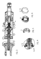
- FIG. 1 The drawing shows a longitudinal sectional view of a vibration damper 1 according to an embodiment of the present invention, which is intended to be arranged on a motorcycle not shown in detail as a vibration damper for the rear of the motorcycle.
- the vibration damper is part of a spring damper assembly or strut 2, with which the rear wheel of the motorcycle leading swingarm not shown is supported on the frame of the motorcycle.
- the shock absorber 2 on a main spring 3, whose oscillatory motion is attenuated via the vibration damper 1.
- the strut 2 can be supported via a strut eye 4 on the rocker or a lever and a second strut eye 5 on the frame.
- the vibration damper 1 has a hollow body or cylinder 6 designed base body, which is provided for filling with damping fluid.
- a working piston or piston 8 is arranged, the fluid passages 9, 10, which are formed by means of valve means 11, 12 in the form of, for example, spring washers or shim stacks or formed with a conical surface as a sealing surface piston valve.
- the spring disk package 11 serves to release a fluid flow from the first working chamber 13 into the second working chamber 14, while the spring disk package 12 serves to release a fluid flow from the working chamber 14 into the working chamber 13.
- the first working space 13 serves as a working space in the compression movement of the strut 2 and the second working space 14 serves as a working space in the rebound movement of the suspension strut 2.
- the piston 8 is arranged on a piston rod 15, which is hollow inside and has an inner space 16.
- apparent fluid communication passage 17 is arranged, via which it can come between the two working spaces 13, 14 for an exchange of damping fluid.
- a first check valve 18 is disposed on the piston rod 5 and in the second working space 14, a second check valve 19, wherein both check valves 18, 19 open in the respective working space.
- a control sleeve 20 is arranged, with a closer reference to Fig. 8 the drawing apparent second adjusting needle 21 along the Axiallnaturescardi the piston rod 15 can be moved.
- the adjusting sleeve 20 is also hollow on the inside with an internal recess 24, specifically for receiving an adjusting rod 22, which is provided for actuating a first adjusting needle 23 arranged in the fluid communication passage 17.
- the adjusting sleeve 20 and the adjusting rod 22 extend through the hollow piston rod 15 in the direction of the interior 7 of the cylinder 6 and out to actuators 25, 26, which are provided in the form of thumbwheels, that is arranged outside of the vibration damper 1 and can be rotated by a user without the aid of tools.
- the adjusting elements 25, 26 are rotatably mounted in a closure lid 27 and are arranged in operative connection with the adjusting sleeve 20 and the adjusting rod 22.
- a rotational movement of the actuating element 25 leads to an axial displacement of the control rod 22, which is supported on the first adjusting needle 23, which in turn is supported by a spring means 28 in the form of a helical compression spring on a sleeve body 29.
- the first adjusting needle 23 can be moved in the direction of the right against the action of the spring device 28 and a rotary actuation of the actuating element 25 in the opposite direction of rotation ensures via the spring device 28 that the first adjusting needle 23 engages the drawing plane is shifted in the left direction.
- a rotary actuation of the actuating element 25 in the opposite direction of rotation ensures via the spring device 28 that the first adjusting needle 23 engages the drawing plane is shifted in the left direction.
- a rotary actuation of the actuating element 26 ensures an axial displacement of the adjusting sleeve 20 in the interior 16 of the piston rod 15, the adjusting sleeve 20 is supported on a collar of the second setting needle 21, which in turn is supported by a spring means 30 on a sleeve body 31.
- a rotational actuation of the actuating element 26 in a rotational direction thus ensures that the adjusting sleeve 20 and thus the second setting needle 21 moves in the plane of the drawing in the direction to the right, while the rotational actuation of the actuating element 26 in the other direction ensures that the spring means 30 the Adjusting sleeve 20 and thus second adjusting needle 21 moves in the plane of the drawing in the direction to the left.
- Both adjusting elements 25, 26 can be secured against inadvertent rotation via a respective screening in the form of, for example, a ball loaded with a spring, which engage in indentations formed on the outer circumference of the circular disk-shaped adjusting elements.
- the vibration damper 1 has a separating piston or sealing disk 32 arranged adjacent to the first working space 13, which forms a receiving space 33 for damping fluid displaced by the piston rod 15.
- a pressure chamber 34 is formed, which is filled in the illustrated embodiment with nitrogen and for pressurizing the damping fluid in the working spaces 13, 14 is used.
- the pressure chamber 34 is separated by a further separating piston 34 against the receiving space 33, wherein the separating piston 34 is arranged axially movable in the cylinder 1, while the separating piston 32 is arranged axially immovable in the cylinder 1, and thus also fulfills the function of a back pressure washer.
- the piston rod 15 in the region of the fluid communication passage 17 has a first passage 36 in the direction of the first working space 13 and a second passage 37 in the direction of second working space 14. Both passages 36, 37 are blocked in the direction of the working spaces 13, 14 out of the check valves 18, 19, so that it can only come to a unidirectional fluid flow in each case.
- the working space 13 acts as a compression chamber and the check valve 18 obstructs fluid flow through the first passage 36 towards the fluid communication passage 37.
- the working fluid in the form of the damping fluid can flow through a third passage 38 in the direction flow to the fluid communication passage 17 and thereby passes to an annular gap space 39 formed in Fluidkommunikations matlass 17 between an end face 40 of the sleeve body 29 and a lense in the illustrated embodiment, the first adjustment needle 23 extension 41, which is spaced in AxiallCodescardi the first adjustment needle 23 to a cylindrical guide portion 42 of the first adjusting needle is arranged and therefore tapers in Axiallnaturesraum the setting needle.
- the damping fluid flowing through the third passage 38 flows along the fluid communication passage 17 and enters the second passage 37 which is closed in the radially inward direction by the second check valve 19 formed as the annular body 43. Since the pressure in the fluid communication passage 17 is higher than the pressure in the second working space 14, the ring body 43 is pushed out radially outward from its seat in the circulation groove 44, and the damping fluid is allowed to relax into the second working space 14.
- the pressure in the second working chamber 14 increases and damping fluid located therein can flow via a fourth passage 45 in the direction of the fluid communication passage 17 stream.
- the second setting needle 21 is arranged with a needle section 46 designed to change a flow cross-section 48.
- the flow cross-section 48 forms an annular gap space 47, which is formed between the outer circumference of the needle portion 46 and a collar 49.
- FIG. 3 The drawing shows a perspective view with a detail "B" in the FIGS. 4 to 6 is shown in different embodiments.
- the detail "B” serves to explain possible embodiments of the check valve 18, which is formed in a preferred embodiment identical to the check valve 19, although various embodiments of check valves, as will be explained below, also in one embodiment of the vibration damper 1 for Use can come.
- the non-return valve is designed as an O-ring 50 arranged in the circumferential groove 44.
- the O-ring 50 bears sealingly in the circulation groove 44 and ensures that no damping fluid can flow from the working space 13 via the check valve in the direction of the fluid communication passage 17.
- the check valve 18 remains closed with its O-ring 50 and prevents leakage of damping fluid from the working space 13 into the fluid communication passage 17th
- the check valve 19 which prevents leakage of damping fluid from the working space 14 in the direction of the fluid communication passage 17 and allows a fluid flow from the working space 13 in the direction of the working chamber 14 during the compression process.
- FIG. 5 The drawing shows a modified embodiment of the check valve 18, 19.
- this embodiment serves as a valve means a tubular piece-shaped elastic body 51 which is arranged with radially inwardly acting bias in the circulation groove 44 of the piston rod 15.
- the function of the check valve thus formed corresponds to the function of the non-return valve formed with an O-ring 50, wherein the check valve formed with the body 51 can be configured so that it opens at an internal pressure in the fluid communication passage 17 which is lower than the opening pressure for the formed with an O-ring 50 check valve 18, 19th
- FIG. 6 The drawing shows a further modified embodiment of a check valve 18, 19.
- a valve means quite generally a tubular body, which is arranged with radially inwardly acting bias in the circulation groove 44 of the piston rod 15.
- the body may be a slotted annular body 52 formed of spring steel which is secured against inadvertent rotation in the circumferential groove 44 by a pin 53 penetrating a bore 54 of the annular body 52.
- a check valve provided with a ring body 52 requires a higher opening pressure than a check valve formed with an O-ring 50, and enables the formation of a small-volume vibration damper 1.
- Fig. 7 The drawing shows a detailed representation of the first adjustment needle 23 according to an embodiment of the present invention.
- the adjusting needle 23 has the already mentioned cylindrical guide portion 42 which is disposed within the fluid communication portion 17.
- the setting needle 23 connects to the guide portion 42 a radially outwardly widening portion 55, in the already in connection with Fig. 2 mentioned section 41, which tapers from the section 55 and the guide portion 42 seen from.
- Fig. 7 As can be seen in the drawing, the section 41, viewed in the axial longitudinal direction, has five sections with different outer diameters, between which the outer diameter in each case increases linearly.
- the section 41 with a largest and a smallest diameter viewed in the axial longitudinal direction of the setting needle 23 and form a change in diameter between the smallest and largest diameter so that the diameter changes linearly, progressively changed, degressive changed or example Envelopes forming a turning point in their slope.
- the adjoining the section 41 section 56 serves to guide the setting needle 23 and the adjoining section 57 serves to receive the spring means 28, via which the adjusting needle 23 is supported on the sleeve body 29.
- FIG. 8 The drawing shows a sectional view of the second adjusting needle 21.
- This has a cylindrical guide portion 58, with which the adjusting needle 21 is axially guided in the inner recess of the sleeve body 31.
- the adjusting needle 21 has a collar 59 on which the spring device 30 is supported, which supports the adjusting needle 21 against the sleeve body 31.
- An axial displacement movement of the adjusting sleeve 20 ensures compression of the spring device 30 in the form of a helical compression spring and that the needle portion 46 of the adjusting needle 21 is displaced relative to the fourth passage 45 so that the annular gap space 47 is reduced.
- a relaxation movement of the spring device 30 ensures that the annular gap space 47 is increased again.
- the needle portion 46 of the second setting needle 21 is tapered as viewed from the guide portion 58. In this way, a displacement movement of the needle portion 46 relative to the collar 49 ensures that the flow cross-section 48 can be increased and decreased and thus the throttle effect can be increased or decreased.
- FIG. 9 The drawing shows a sectional view of a vibration damper 60 according to a modified embodiment.
- the vibration damper 60 again has a second adjusting needle 21, a first adjusting needle 23 and two check valves 18, 19 equipped with O-rings 50.
- the vibration damper 60 has a cylinder 61 of shorter length than the cylinder 6, which is realized in that the receiving space 33 for damping fluid and the pressure chamber 34 have been moved out of the cylinder 61 and has been moved to an external housing 62 are.
- the interior of the housing 62 is in fluid communication with the interior of the cylinder 61, so that from the cylinder 61 damping fluid can be moved in the interior of the housing 62 in a compression movement and in a rebound movement again in accordance with the interior of the cylinder 61 can be moved back ,
- the vibration damper 60 has the advantage of shorter overall length and can therefore be installed on a vehicle, for example a motorcycle, not shown, in which less receiving space for the installation of a vibration damper according to the invention is available.
- the vibration damper according to the invention has the advantage that check valves can be used, which are made of a material with a low modulus of elasticity. This leads to a very sensitive response of the vibration damper, as it is for example in racing a great advantage.
- the possibility of forming the valve device of the check valves as an O-ring means that the valve devices can be exchanged very easily and can be exchanged for valve devices with a different opening behavior. This, for example, in racing a great advantage, since so the response of the shock absorber on the racetrack can be changed quickly, for this purpose, the simple replacement of the two adjusting needles significantly contributes.
- the adjusting needles can be provided with sections for changing the available for the flow of damping fluid annular gap space, which can be adapted to different requirements, for example, route-specific.
- Already assembled adjustment needles can be easily replaced with adjustment needles with other needle sections by removing them from the interior of the piston rod and replacing them with other adjustment needles.
- the actuation of the adjusting needles only requires an axial movement of the adjusting device in the form of the adjusting sleeve and the adjusting rod, which can be implemented by a simple rotary actuation of the outside of the vibration damper control elements in the form of knurled or thumbwheels.
- the user recognizes on the basis of the direction of rotation of the operation of the thumbwheels or thumbwheels, in which direction he changes the damping characteristic, ie in the direction of pull more damping or less damping and pressure more damping or less damping.
- the impact of the user-induced change is therefore clear and unambiguous.
- the use of radially acting check valves ensures a cost-effective design of the vibration damper according to the invention and the vibration damper also has the advantage that the compression damping and the rebound damping are completely independent of each other adjustable.
- the inventive Vibration damper is suitable for use with a mono-tube spring damper, twin-tube spring damper, carbon fiber type shock absorbers, to name a few.
Landscapes
- Engineering & Computer Science (AREA)
- General Engineering & Computer Science (AREA)
- Mechanical Engineering (AREA)
- Fluid-Damping Devices (AREA)
Applications Claiming Priority (1)
| Application Number | Priority Date | Filing Date | Title |
|---|---|---|---|
| DE102014112523.1A DE102014112523A1 (de) | 2014-09-01 | 2014-09-01 | Schwingungsdämpfer mit unabhängig voneinander einstellbarer Dämpfung für die Zugstufe und die Druckstufe |
Publications (3)
| Publication Number | Publication Date |
|---|---|
| EP3009708A2 true EP3009708A2 (fr) | 2016-04-20 |
| EP3009708A3 EP3009708A3 (fr) | 2016-12-21 |
| EP3009708B1 EP3009708B1 (fr) | 2018-01-17 |
Family
ID=53879429
Family Applications (1)
| Application Number | Title | Priority Date | Filing Date |
|---|---|---|---|
| EP15181550.3A Active EP3009708B1 (fr) | 2014-09-01 | 2015-08-19 | Amortisseur d'oscillations avec amortissement autonome reglable pour le palier de pression et le palier de traction |
Country Status (3)
| Country | Link |
|---|---|
| EP (1) | EP3009708B1 (fr) |
| DE (1) | DE102014112523A1 (fr) |
| ES (1) | ES2664832T3 (fr) |
Cited By (4)
| Publication number | Priority date | Publication date | Assignee | Title |
|---|---|---|---|---|
| JP6198926B1 (ja) * | 2016-12-19 | 2017-09-20 | 株式会社キャロッセ | 油圧緩衝器 |
| CN114718975A (zh) * | 2021-01-04 | 2022-07-08 | 常州中车柴油机零部件有限公司 | 液压减振器以及轨道车辆 |
| CN116877617A (zh) * | 2023-07-14 | 2023-10-13 | 泉州市博汉机械股份有限公司 | 一种单项阻尼调节减震器 |
| CN120845481A (zh) * | 2025-09-22 | 2025-10-28 | 江苏科曼赛特减振器有限公司 | 氮气减振器及其减振方法 |
Families Citing this family (3)
| Publication number | Priority date | Publication date | Assignee | Title |
|---|---|---|---|---|
| DE102018114679B3 (de) | 2018-06-19 | 2019-05-02 | Ktm Ag | Schwingungsdämpfer |
| DE102019216491A1 (de) * | 2019-03-07 | 2020-09-10 | Zf Friedrichshafen Ag | Nadelventil |
| JP6533026B1 (ja) | 2019-04-04 | 2019-06-19 | 株式会社ショーワ | 緩衝器 |
Citations (8)
| Publication number | Priority date | Publication date | Assignee | Title |
|---|---|---|---|---|
| DE3608738A1 (de) | 1986-03-15 | 1987-09-17 | Fichtel & Sachs Ag | Hydraulischer schwingungsdaempfer mit einstellbarer daempfkraft |
| DE4103356C1 (en) | 1991-02-05 | 1992-06-17 | Boge Ag, 5208 Eitorf, De | Hydraulic vibration damper with valved piston - has control body active face of several, angularly-set, individual faces |
| EP1473483B1 (fr) | 2003-04-30 | 2006-02-01 | ThyssenKrupp Bilstein GmbH | Amortisseur hydraulique |
| DE102004014458B4 (de) | 2003-03-27 | 2007-11-08 | Kayaba Industry Co., Ltd. | Vordergabel |
| DE102006052228B4 (de) | 2005-11-07 | 2010-08-19 | Kayaba Industry Co., Ltd. | Vordergabel mit eingebautem Dämpfer |
| EP2110300B1 (fr) | 2008-04-17 | 2012-06-27 | Kayaba Industry Co., Ltd. | Fourche avant |
| US8235187B2 (en) | 2007-09-28 | 2012-08-07 | Showa Corporation | Hydraulic shock absorber |
| US8276719B2 (en) | 2008-05-09 | 2012-10-02 | Specialized Bicycle Components, Inc. | Bicycle damper |
Family Cites Families (4)
| Publication number | Priority date | Publication date | Assignee | Title |
|---|---|---|---|---|
| JP2002181114A (ja) * | 2000-12-13 | 2002-06-26 | Sadao Sakugi | 油圧緩衝器の減衰力調整機構 |
| JP2002235788A (ja) * | 2001-02-06 | 2002-08-23 | Sadao Sakugi | 油圧緩衝器の減衰力調整機構 |
| IT1391919B1 (it) * | 2008-09-17 | 2012-02-02 | Quirini | Ammortizzatore oleodinamico |
| DE102011053127A1 (de) * | 2011-08-30 | 2013-02-28 | B-Labs Ag | Feder-Dämpfervorrichtung für ein Fahrrad |
-
2014
- 2014-09-01 DE DE102014112523.1A patent/DE102014112523A1/de not_active Withdrawn
-
2015
- 2015-08-19 ES ES15181550.3T patent/ES2664832T3/es active Active
- 2015-08-19 EP EP15181550.3A patent/EP3009708B1/fr active Active
Patent Citations (8)
| Publication number | Priority date | Publication date | Assignee | Title |
|---|---|---|---|---|
| DE3608738A1 (de) | 1986-03-15 | 1987-09-17 | Fichtel & Sachs Ag | Hydraulischer schwingungsdaempfer mit einstellbarer daempfkraft |
| DE4103356C1 (en) | 1991-02-05 | 1992-06-17 | Boge Ag, 5208 Eitorf, De | Hydraulic vibration damper with valved piston - has control body active face of several, angularly-set, individual faces |
| DE102004014458B4 (de) | 2003-03-27 | 2007-11-08 | Kayaba Industry Co., Ltd. | Vordergabel |
| EP1473483B1 (fr) | 2003-04-30 | 2006-02-01 | ThyssenKrupp Bilstein GmbH | Amortisseur hydraulique |
| DE102006052228B4 (de) | 2005-11-07 | 2010-08-19 | Kayaba Industry Co., Ltd. | Vordergabel mit eingebautem Dämpfer |
| US8235187B2 (en) | 2007-09-28 | 2012-08-07 | Showa Corporation | Hydraulic shock absorber |
| EP2110300B1 (fr) | 2008-04-17 | 2012-06-27 | Kayaba Industry Co., Ltd. | Fourche avant |
| US8276719B2 (en) | 2008-05-09 | 2012-10-02 | Specialized Bicycle Components, Inc. | Bicycle damper |
Cited By (4)
| Publication number | Priority date | Publication date | Assignee | Title |
|---|---|---|---|---|
| JP6198926B1 (ja) * | 2016-12-19 | 2017-09-20 | 株式会社キャロッセ | 油圧緩衝器 |
| CN114718975A (zh) * | 2021-01-04 | 2022-07-08 | 常州中车柴油机零部件有限公司 | 液压减振器以及轨道车辆 |
| CN116877617A (zh) * | 2023-07-14 | 2023-10-13 | 泉州市博汉机械股份有限公司 | 一种单项阻尼调节减震器 |
| CN120845481A (zh) * | 2025-09-22 | 2025-10-28 | 江苏科曼赛特减振器有限公司 | 氮气减振器及其减振方法 |
Also Published As
| Publication number | Publication date |
|---|---|
| EP3009708A3 (fr) | 2016-12-21 |
| ES2664832T3 (es) | 2018-04-23 |
| EP3009708B1 (fr) | 2018-01-17 |
| DE102014112523A1 (de) | 2016-03-17 |
Similar Documents
| Publication | Publication Date | Title |
|---|---|---|
| EP3009708B1 (fr) | Amortisseur d'oscillations avec amortissement autonome reglable pour le palier de pression et le palier de traction | |
| DE3914297C2 (fr) | ||
| DE3304815C2 (de) | Teleskop-Stoßdämpfer mit einstellbarer Dämpfungswirkung | |
| DE3303293C2 (de) | Hydraulischer Teleskop-Stoßdämpfer mit verstellbarer Dämpfung für Fahrzeuge | |
| EP2255103B1 (fr) | Amortisseur de vibrations comportant une soupape attachée au tube d'amortisseur | |
| DE102018201297B4 (de) | Schwingungsdämpfer für ein Fahrzeug | |
| DE112013004595B4 (de) | Aufhängungsvorrichtung | |
| EP2565491A2 (fr) | Dispositif d'amortissement à ressort pour un vélo | |
| DE102010040226B4 (de) | Fluiddruckstoßdämpfer | |
| EP4461986A1 (fr) | Amortisseur de chocs | |
| DE202023104556U1 (de) | Stoßdämpfer | |
| DE2364855A1 (de) | Stossdaempfer | |
| DE2757711C2 (de) | Hydraulischer Teleskopstoßdämpfer für ein Motorrad | |
| DE102022129375A1 (de) | Schwingungsdämpfer, Fahrradgabel, Federbein sowie Verwendung eines Schwingungsdämpfers | |
| EP3584464B1 (fr) | Amortisseur | |
| DE3814480A1 (de) | Vorrichtung zur daempfung von bewegungsablaeufen | |
| DE19743543A1 (de) | Stoßdämpferanordnung und Verfahren zur Stoßdämpfung | |
| EP1281888B1 (fr) | Amortisseur hydraulique | |
| DE19501490A1 (de) | Hydropneumatisches Federbein, insbesondere für eine Gabel eines Fahrrades | |
| DE3604844C2 (fr) | ||
| EP4506587B1 (fr) | Amortisseur de chocs | |
| DE3503153A1 (de) | Schwingungsdaempfer fuer fahrzeuge | |
| EP2439424A2 (fr) | Amortisseur d'oscillations en fonction de la fréquence dans une construction à deux tuyaux | |
| DE102007018582B4 (de) | Kolben-Zylinderaggregat | |
| EP1592571A1 (fr) | Dispositif pour amortir l'inclinaison de la carrosserie d'un vehicule |
Legal Events
| Date | Code | Title | Description |
|---|---|---|---|
| PUAI | Public reference made under article 153(3) epc to a published international application that has entered the european phase |
Free format text: ORIGINAL CODE: 0009012 |
|
| AK | Designated contracting states |
Kind code of ref document: A2 Designated state(s): AL AT BE BG CH CY CZ DE DK EE ES FI FR GB GR HR HU IE IS IT LI LT LU LV MC MK MT NL NO PL PT RO RS SE SI SK SM TR |
|
| AX | Request for extension of the european patent |
Extension state: BA ME |
|
| PUAL | Search report despatched |
Free format text: ORIGINAL CODE: 0009013 |
|
| AK | Designated contracting states |
Kind code of ref document: A3 Designated state(s): AL AT BE BG CH CY CZ DE DK EE ES FI FR GB GR HR HU IE IS IT LI LT LU LV MC MK MT NL NO PL PT RO RS SE SI SK SM TR |
|
| AX | Request for extension of the european patent |
Extension state: BA ME |
|
| RIC1 | Information provided on ipc code assigned before grant |
Ipc: F16F 9/46 20060101AFI20161114BHEP Ipc: F16F 9/06 20060101ALI20161114BHEP |
|
| STAA | Information on the status of an ep patent application or granted ep patent |
Free format text: STATUS: REQUEST FOR EXAMINATION WAS MADE |
|
| 17P | Request for examination filed |
Effective date: 20170301 |
|
| RBV | Designated contracting states (corrected) |
Designated state(s): AL AT BE BG CH CY CZ DE DK EE ES FI FR GB GR HR HU IE IS IT LI LT LU LV MC MK MT NL NO PL PT RO RS SE SI SK SM TR |
|
| GRAP | Despatch of communication of intention to grant a patent |
Free format text: ORIGINAL CODE: EPIDOSNIGR1 |
|
| STAA | Information on the status of an ep patent application or granted ep patent |
Free format text: STATUS: GRANT OF PATENT IS INTENDED |
|
| INTG | Intention to grant announced |
Effective date: 20170623 |
|
| GRAJ | Information related to disapproval of communication of intention to grant by the applicant or resumption of examination proceedings by the epo deleted |
Free format text: ORIGINAL CODE: EPIDOSDIGR1 |
|
| STAA | Information on the status of an ep patent application or granted ep patent |
Free format text: STATUS: REQUEST FOR EXAMINATION WAS MADE |
|
| GRAP | Despatch of communication of intention to grant a patent |
Free format text: ORIGINAL CODE: EPIDOSNIGR1 |
|
| STAA | Information on the status of an ep patent application or granted ep patent |
Free format text: STATUS: GRANT OF PATENT IS INTENDED |
|
| INTC | Intention to grant announced (deleted) | ||
| INTG | Intention to grant announced |
Effective date: 20171109 |
|
| GRAS | Grant fee paid |
Free format text: ORIGINAL CODE: EPIDOSNIGR3 |
|
| GRAA | (expected) grant |
Free format text: ORIGINAL CODE: 0009210 |
|
| STAA | Information on the status of an ep patent application or granted ep patent |
Free format text: STATUS: THE PATENT HAS BEEN GRANTED |
|
| AK | Designated contracting states |
Kind code of ref document: B1 Designated state(s): AL AT BE BG CH CY CZ DE DK EE ES FI FR GB GR HR HU IE IS IT LI LT LU LV MC MK MT NL NO PL PT RO RS SE SI SK SM TR |
|
| REG | Reference to a national code |
Ref country code: GB Ref legal event code: FG4D Free format text: NOT ENGLISH |
|
| REG | Reference to a national code |
Ref country code: CH Ref legal event code: EP |
|
| REG | Reference to a national code |
Ref country code: IE Ref legal event code: FG4D Free format text: LANGUAGE OF EP DOCUMENT: GERMAN |
|
| REG | Reference to a national code |
Ref country code: DE Ref legal event code: R096 Ref document number: 502015002864 Country of ref document: DE Ref country code: AT Ref legal event code: REF Ref document number: 964646 Country of ref document: AT Kind code of ref document: T Effective date: 20180215 |
|
| REG | Reference to a national code |
Ref country code: ES Ref legal event code: FG2A Ref document number: 2664832 Country of ref document: ES Kind code of ref document: T3 Effective date: 20180423 |
|
| REG | Reference to a national code |
Ref country code: SE Ref legal event code: TRGR |
|
| REG | Reference to a national code |
Ref country code: NL Ref legal event code: MP Effective date: 20180117 |
|
| REG | Reference to a national code |
Ref country code: LT Ref legal event code: MG4D |
|
| PG25 | Lapsed in a contracting state [announced via postgrant information from national office to epo] |
Ref country code: NL Free format text: LAPSE BECAUSE OF FAILURE TO SUBMIT A TRANSLATION OF THE DESCRIPTION OR TO PAY THE FEE WITHIN THE PRESCRIBED TIME-LIMIT Effective date: 20180117 |
|
| PG25 | Lapsed in a contracting state [announced via postgrant information from national office to epo] |
Ref country code: LT Free format text: LAPSE BECAUSE OF FAILURE TO SUBMIT A TRANSLATION OF THE DESCRIPTION OR TO PAY THE FEE WITHIN THE PRESCRIBED TIME-LIMIT Effective date: 20180117 Ref country code: CY Free format text: LAPSE BECAUSE OF FAILURE TO SUBMIT A TRANSLATION OF THE DESCRIPTION OR TO PAY THE FEE WITHIN THE PRESCRIBED TIME-LIMIT Effective date: 20180117 Ref country code: FI Free format text: LAPSE BECAUSE OF FAILURE TO SUBMIT A TRANSLATION OF THE DESCRIPTION OR TO PAY THE FEE WITHIN THE PRESCRIBED TIME-LIMIT Effective date: 20180117 Ref country code: HR Free format text: LAPSE BECAUSE OF FAILURE TO SUBMIT A TRANSLATION OF THE DESCRIPTION OR TO PAY THE FEE WITHIN THE PRESCRIBED TIME-LIMIT Effective date: 20180117 Ref country code: NO Free format text: LAPSE BECAUSE OF FAILURE TO SUBMIT A TRANSLATION OF THE DESCRIPTION OR TO PAY THE FEE WITHIN THE PRESCRIBED TIME-LIMIT Effective date: 20180417 |
|
| REG | Reference to a national code |
Ref country code: FR Ref legal event code: PLFP Year of fee payment: 4 |
|
| PG25 | Lapsed in a contracting state [announced via postgrant information from national office to epo] |
Ref country code: GR Free format text: LAPSE BECAUSE OF FAILURE TO SUBMIT A TRANSLATION OF THE DESCRIPTION OR TO PAY THE FEE WITHIN THE PRESCRIBED TIME-LIMIT Effective date: 20180418 Ref country code: BG Free format text: LAPSE BECAUSE OF FAILURE TO SUBMIT A TRANSLATION OF THE DESCRIPTION OR TO PAY THE FEE WITHIN THE PRESCRIBED TIME-LIMIT Effective date: 20180417 Ref country code: RS Free format text: LAPSE BECAUSE OF FAILURE TO SUBMIT A TRANSLATION OF THE DESCRIPTION OR TO PAY THE FEE WITHIN THE PRESCRIBED TIME-LIMIT Effective date: 20180117 Ref country code: IS Free format text: LAPSE BECAUSE OF FAILURE TO SUBMIT A TRANSLATION OF THE DESCRIPTION OR TO PAY THE FEE WITHIN THE PRESCRIBED TIME-LIMIT Effective date: 20180517 Ref country code: PL Free format text: LAPSE BECAUSE OF FAILURE TO SUBMIT A TRANSLATION OF THE DESCRIPTION OR TO PAY THE FEE WITHIN THE PRESCRIBED TIME-LIMIT Effective date: 20180117 Ref country code: LV Free format text: LAPSE BECAUSE OF FAILURE TO SUBMIT A TRANSLATION OF THE DESCRIPTION OR TO PAY THE FEE WITHIN THE PRESCRIBED TIME-LIMIT Effective date: 20180117 |
|
| PG25 | Lapsed in a contracting state [announced via postgrant information from national office to epo] |
Ref country code: MT Free format text: LAPSE BECAUSE OF FAILURE TO SUBMIT A TRANSLATION OF THE DESCRIPTION OR TO PAY THE FEE WITHIN THE PRESCRIBED TIME-LIMIT Effective date: 20180117 |
|
| REG | Reference to a national code |
Ref country code: DE Ref legal event code: R097 Ref document number: 502015002864 Country of ref document: DE |
|
| PG25 | Lapsed in a contracting state [announced via postgrant information from national office to epo] |
Ref country code: RO Free format text: LAPSE BECAUSE OF FAILURE TO SUBMIT A TRANSLATION OF THE DESCRIPTION OR TO PAY THE FEE WITHIN THE PRESCRIBED TIME-LIMIT Effective date: 20180117 Ref country code: EE Free format text: LAPSE BECAUSE OF FAILURE TO SUBMIT A TRANSLATION OF THE DESCRIPTION OR TO PAY THE FEE WITHIN THE PRESCRIBED TIME-LIMIT Effective date: 20180117 Ref country code: AL Free format text: LAPSE BECAUSE OF FAILURE TO SUBMIT A TRANSLATION OF THE DESCRIPTION OR TO PAY THE FEE WITHIN THE PRESCRIBED TIME-LIMIT Effective date: 20180117 |
|
| PLBE | No opposition filed within time limit |
Free format text: ORIGINAL CODE: 0009261 |
|
| STAA | Information on the status of an ep patent application or granted ep patent |
Free format text: STATUS: NO OPPOSITION FILED WITHIN TIME LIMIT |
|
| PG25 | Lapsed in a contracting state [announced via postgrant information from national office to epo] |
Ref country code: SM Free format text: LAPSE BECAUSE OF FAILURE TO SUBMIT A TRANSLATION OF THE DESCRIPTION OR TO PAY THE FEE WITHIN THE PRESCRIBED TIME-LIMIT Effective date: 20180117 Ref country code: DK Free format text: LAPSE BECAUSE OF FAILURE TO SUBMIT A TRANSLATION OF THE DESCRIPTION OR TO PAY THE FEE WITHIN THE PRESCRIBED TIME-LIMIT Effective date: 20180117 Ref country code: CZ Free format text: LAPSE BECAUSE OF FAILURE TO SUBMIT A TRANSLATION OF THE DESCRIPTION OR TO PAY THE FEE WITHIN THE PRESCRIBED TIME-LIMIT Effective date: 20180117 Ref country code: SK Free format text: LAPSE BECAUSE OF FAILURE TO SUBMIT A TRANSLATION OF THE DESCRIPTION OR TO PAY THE FEE WITHIN THE PRESCRIBED TIME-LIMIT Effective date: 20180117 |
|
| REG | Reference to a national code |
Ref country code: DE Ref legal event code: R082 Ref document number: 502015002864 Country of ref document: DE Representative=s name: SOELLNER, UDO, DIPL.-ING.UNIV., DE Ref country code: DE Ref legal event code: R081 Ref document number: 502015002864 Country of ref document: DE Owner name: KTM COMPONENTS GMBH, AT Free format text: FORMER OWNER: WP PERFORMANCE SYSTEMS GMBH, MUNDERFING, AT |
|
| 26N | No opposition filed |
Effective date: 20181018 |
|
| PG25 | Lapsed in a contracting state [announced via postgrant information from national office to epo] |
Ref country code: SI Free format text: LAPSE BECAUSE OF FAILURE TO SUBMIT A TRANSLATION OF THE DESCRIPTION OR TO PAY THE FEE WITHIN THE PRESCRIBED TIME-LIMIT Effective date: 20180117 |
|
| PG25 | Lapsed in a contracting state [announced via postgrant information from national office to epo] |
Ref country code: MC Free format text: LAPSE BECAUSE OF FAILURE TO SUBMIT A TRANSLATION OF THE DESCRIPTION OR TO PAY THE FEE WITHIN THE PRESCRIBED TIME-LIMIT Effective date: 20180117 |
|
| REG | Reference to a national code |
Ref country code: CH Ref legal event code: PL |
|
| PG25 | Lapsed in a contracting state [announced via postgrant information from national office to epo] |
Ref country code: LU Free format text: LAPSE BECAUSE OF NON-PAYMENT OF DUE FEES Effective date: 20180819 Ref country code: LI Free format text: LAPSE BECAUSE OF NON-PAYMENT OF DUE FEES Effective date: 20180831 Ref country code: CH Free format text: LAPSE BECAUSE OF NON-PAYMENT OF DUE FEES Effective date: 20180831 |
|
| REG | Reference to a national code |
Ref country code: BE Ref legal event code: MM Effective date: 20180831 |
|
| REG | Reference to a national code |
Ref country code: IE Ref legal event code: MM4A |
|
| REG | Reference to a national code |
Ref country code: AT Ref legal event code: HC Ref document number: 964646 Country of ref document: AT Kind code of ref document: T Owner name: KTM COMPONENTS GMBH, AT Effective date: 20190612 |
|
| PG25 | Lapsed in a contracting state [announced via postgrant information from national office to epo] |
Ref country code: IE Free format text: LAPSE BECAUSE OF NON-PAYMENT OF DUE FEES Effective date: 20180819 |
|
| PG25 | Lapsed in a contracting state [announced via postgrant information from national office to epo] |
Ref country code: BE Free format text: LAPSE BECAUSE OF NON-PAYMENT OF DUE FEES Effective date: 20180831 |
|
| REG | Reference to a national code |
Ref country code: ES Ref legal event code: PC2A Owner name: KTM COMPONENTS GMBH Effective date: 20190924 |
|
| PG25 | Lapsed in a contracting state [announced via postgrant information from national office to epo] |
Ref country code: TR Free format text: LAPSE BECAUSE OF FAILURE TO SUBMIT A TRANSLATION OF THE DESCRIPTION OR TO PAY THE FEE WITHIN THE PRESCRIBED TIME-LIMIT Effective date: 20180117 |
|
| GBPC | Gb: european patent ceased through non-payment of renewal fee |
Effective date: 20190819 |
|
| PG25 | Lapsed in a contracting state [announced via postgrant information from national office to epo] |
Ref country code: PT Free format text: LAPSE BECAUSE OF FAILURE TO SUBMIT A TRANSLATION OF THE DESCRIPTION OR TO PAY THE FEE WITHIN THE PRESCRIBED TIME-LIMIT Effective date: 20180117 |
|
| PG25 | Lapsed in a contracting state [announced via postgrant information from national office to epo] |
Ref country code: MK Free format text: LAPSE BECAUSE OF NON-PAYMENT OF DUE FEES Effective date: 20180117 Ref country code: HU Free format text: LAPSE BECAUSE OF FAILURE TO SUBMIT A TRANSLATION OF THE DESCRIPTION OR TO PAY THE FEE WITHIN THE PRESCRIBED TIME-LIMIT; INVALID AB INITIO Effective date: 20150819 |
|
| PG25 | Lapsed in a contracting state [announced via postgrant information from national office to epo] |
Ref country code: GB Free format text: LAPSE BECAUSE OF NON-PAYMENT OF DUE FEES Effective date: 20190819 |
|
| P01 | Opt-out of the competence of the unified patent court (upc) registered |
Effective date: 20230514 |
|
| PGFP | Annual fee paid to national office [announced via postgrant information from national office to epo] |
Ref country code: ES Payment date: 20250917 Year of fee payment: 11 |
|
| PGFP | Annual fee paid to national office [announced via postgrant information from national office to epo] |
Ref country code: DE Payment date: 20250605 Year of fee payment: 11 |
|
| PGFP | Annual fee paid to national office [announced via postgrant information from national office to epo] |
Ref country code: IT Payment date: 20250829 Year of fee payment: 11 |
|
| PGFP | Annual fee paid to national office [announced via postgrant information from national office to epo] |
Ref country code: FR Payment date: 20250821 Year of fee payment: 11 Ref country code: AT Payment date: 20250819 Year of fee payment: 11 |
|
| PGFP | Annual fee paid to national office [announced via postgrant information from national office to epo] |
Ref country code: SE Payment date: 20250821 Year of fee payment: 11 |