EP3009767A1 - Wärmepumpenvorrichtung - Google Patents
Wärmepumpenvorrichtung Download PDFInfo
- Publication number
- EP3009767A1 EP3009767A1 EP13886812.0A EP13886812A EP3009767A1 EP 3009767 A1 EP3009767 A1 EP 3009767A1 EP 13886812 A EP13886812 A EP 13886812A EP 3009767 A1 EP3009767 A1 EP 3009767A1
- Authority
- EP
- European Patent Office
- Prior art keywords
- refrigerant
- heat transfer
- pipe
- gas cooler
- twist
- Prior art date
- Legal status (The legal status is an assumption and is not a legal conclusion. Google has not performed a legal analysis and makes no representation as to the accuracy of the status listed.)
- Granted
Links
Images




Classifications
-
- F—MECHANICAL ENGINEERING; LIGHTING; HEATING; WEAPONS; BLASTING
- F25—REFRIGERATION OR COOLING; COMBINED HEATING AND REFRIGERATION SYSTEMS; HEAT PUMP SYSTEMS; MANUFACTURE OR STORAGE OF ICE; LIQUEFACTION SOLIDIFICATION OF GASES
- F25B—REFRIGERATION MACHINES, PLANTS OR SYSTEMS; COMBINED HEATING AND REFRIGERATION SYSTEMS; HEAT PUMP SYSTEMS
- F25B30/00—Heat pumps
- F25B30/02—Heat pumps of the compression type
-
- F—MECHANICAL ENGINEERING; LIGHTING; HEATING; WEAPONS; BLASTING
- F04—POSITIVE - DISPLACEMENT MACHINES FOR LIQUIDS; PUMPS FOR LIQUIDS OR ELASTIC FLUIDS
- F04B—POSITIVE-DISPLACEMENT MACHINES FOR LIQUIDS; PUMPS
- F04B39/00—Component parts, details, or accessories, of pumps or pumping systems specially adapted for elastic fluids, not otherwise provided for in, or of interest apart from, groups F04B25/00 - F04B37/00
- F04B39/06—Cooling; Heating; Prevention of freezing
-
- F—MECHANICAL ENGINEERING; LIGHTING; HEATING; WEAPONS; BLASTING
- F04—POSITIVE - DISPLACEMENT MACHINES FOR LIQUIDS; PUMPS FOR LIQUIDS OR ELASTIC FLUIDS
- F04C—ROTARY-PISTON, OR OSCILLATING-PISTON, POSITIVE-DISPLACEMENT MACHINES FOR LIQUIDS; ROTARY-PISTON, OR OSCILLATING-PISTON, POSITIVE-DISPLACEMENT PUMPS
- F04C23/00—Combinations of two or more pumps, each being of rotary-piston or oscillating-piston type, specially adapted for elastic fluids; Pumping installations specially adapted for elastic fluids; Multi-stage pumps specially adapted for elastic fluids
- F04C23/008—Hermetic pumps
-
- F—MECHANICAL ENGINEERING; LIGHTING; HEATING; WEAPONS; BLASTING
- F25—REFRIGERATION OR COOLING; COMBINED HEATING AND REFRIGERATION SYSTEMS; HEAT PUMP SYSTEMS; MANUFACTURE OR STORAGE OF ICE; LIQUEFACTION SOLIDIFICATION OF GASES
- F25B—REFRIGERATION MACHINES, PLANTS OR SYSTEMS; COMBINED HEATING AND REFRIGERATION SYSTEMS; HEAT PUMP SYSTEMS
- F25B40/00—Subcoolers, desuperheaters or superheaters
-
- F—MECHANICAL ENGINEERING; LIGHTING; HEATING; WEAPONS; BLASTING
- F28—HEAT EXCHANGE IN GENERAL
- F28D—HEAT-EXCHANGE APPARATUS, NOT PROVIDED FOR IN ANOTHER SUBCLASS, IN WHICH THE HEAT-EXCHANGE MEDIA DO NOT COME INTO DIRECT CONTACT
- F28D7/00—Heat-exchange apparatus having stationary tubular conduit assemblies for both heat-exchange media, the media being in contact with different sides of a conduit wall
- F28D7/0008—Heat-exchange apparatus having stationary tubular conduit assemblies for both heat-exchange media, the media being in contact with different sides of a conduit wall the conduits for one medium being in heat conductive contact with the conduits for the other medium
- F28D7/0016—Heat-exchange apparatus having stationary tubular conduit assemblies for both heat-exchange media, the media being in contact with different sides of a conduit wall the conduits for one medium being in heat conductive contact with the conduits for the other medium the conduits for one medium or the conduits for both media being bent
-
- F—MECHANICAL ENGINEERING; LIGHTING; HEATING; WEAPONS; BLASTING
- F28—HEAT EXCHANGE IN GENERAL
- F28D—HEAT-EXCHANGE APPARATUS, NOT PROVIDED FOR IN ANOTHER SUBCLASS, IN WHICH THE HEAT-EXCHANGE MEDIA DO NOT COME INTO DIRECT CONTACT
- F28D7/00—Heat-exchange apparatus having stationary tubular conduit assemblies for both heat-exchange media, the media being in contact with different sides of a conduit wall
- F28D7/0066—Multi-circuit heat-exchangers, e.g. integrating different heat exchange sections in the same unit or heat-exchangers for more than two fluids
-
- F—MECHANICAL ENGINEERING; LIGHTING; HEATING; WEAPONS; BLASTING
- F28—HEAT EXCHANGE IN GENERAL
- F28D—HEAT-EXCHANGE APPARATUS, NOT PROVIDED FOR IN ANOTHER SUBCLASS, IN WHICH THE HEAT-EXCHANGE MEDIA DO NOT COME INTO DIRECT CONTACT
- F28D7/00—Heat-exchange apparatus having stationary tubular conduit assemblies for both heat-exchange media, the media being in contact with different sides of a conduit wall
- F28D7/02—Heat-exchange apparatus having stationary tubular conduit assemblies for both heat-exchange media, the media being in contact with different sides of a conduit wall the conduits being helically coiled
- F28D7/024—Heat-exchange apparatus having stationary tubular conduit assemblies for both heat-exchange media, the media being in contact with different sides of a conduit wall the conduits being helically coiled the conduits of only one medium being helically coiled tubes, the coils having a cylindrical configuration
-
- F—MECHANICAL ENGINEERING; LIGHTING; HEATING; WEAPONS; BLASTING
- F28—HEAT EXCHANGE IN GENERAL
- F28F—DETAILS OF HEAT-EXCHANGE AND HEAT-TRANSFER APPARATUS, OF GENERAL APPLICATION
- F28F1/00—Tubular elements; Assemblies of tubular elements
- F28F1/02—Tubular elements of cross-section which is non-circular
-
- F—MECHANICAL ENGINEERING; LIGHTING; HEATING; WEAPONS; BLASTING
- F28—HEAT EXCHANGE IN GENERAL
- F28F—DETAILS OF HEAT-EXCHANGE AND HEAT-TRANSFER APPARATUS, OF GENERAL APPLICATION
- F28F1/00—Tubular elements; Assemblies of tubular elements
- F28F1/10—Tubular elements and assemblies thereof with means for increasing heat-transfer area, e.g. with fins, with projections, with recesses
- F28F1/12—Tubular elements and assemblies thereof with means for increasing heat-transfer area, e.g. with fins, with projections, with recesses the means being only outside the tubular element
- F28F1/34—Tubular elements and assemblies thereof with means for increasing heat-transfer area, e.g. with fins, with projections, with recesses the means being only outside the tubular element and extending obliquely
- F28F1/36—Tubular elements and assemblies thereof with means for increasing heat-transfer area, e.g. with fins, with projections, with recesses the means being only outside the tubular element and extending obliquely the means being helically wound fins or wire spirals
-
- F—MECHANICAL ENGINEERING; LIGHTING; HEATING; WEAPONS; BLASTING
- F25—REFRIGERATION OR COOLING; COMBINED HEATING AND REFRIGERATION SYSTEMS; HEAT PUMP SYSTEMS; MANUFACTURE OR STORAGE OF ICE; LIQUEFACTION SOLIDIFICATION OF GASES
- F25B—REFRIGERATION MACHINES, PLANTS OR SYSTEMS; COMBINED HEATING AND REFRIGERATION SYSTEMS; HEAT PUMP SYSTEMS
- F25B2339/00—Details of evaporators; Details of condensers
- F25B2339/04—Details of condensers
- F25B2339/047—Water-cooled condensers
-
- F—MECHANICAL ENGINEERING; LIGHTING; HEATING; WEAPONS; BLASTING
- F25—REFRIGERATION OR COOLING; COMBINED HEATING AND REFRIGERATION SYSTEMS; HEAT PUMP SYSTEMS; MANUFACTURE OR STORAGE OF ICE; LIQUEFACTION SOLIDIFICATION OF GASES
- F25B—REFRIGERATION MACHINES, PLANTS OR SYSTEMS; COMBINED HEATING AND REFRIGERATION SYSTEMS; HEAT PUMP SYSTEMS
- F25B2400/00—Component parts or details not otherwise provided for in this subclass
- F25B2400/07—Details of compressors or related parts
- F25B2400/072—Intercoolers therefor
-
- F—MECHANICAL ENGINEERING; LIGHTING; HEATING; WEAPONS; BLASTING
- F28—HEAT EXCHANGE IN GENERAL
- F28F—DETAILS OF HEAT-EXCHANGE AND HEAT-TRANSFER APPARATUS, OF GENERAL APPLICATION
- F28F2275/00—Fastening; Joining
- F28F2275/06—Fastening; Joining by welding
Definitions
- the present invention relates to a heat pump device.
- Patent Literature 1 discloses a hot-water supply cycle device including: a gas cooler having high temperature side refrigerant piping, low temperature side refrigerant piping, and water piping; and a hot-water supply compressor having a sealed container, a compressing element, an electric actuating element, an intake pipe, a discharge pipe, a refrigerant reintroduction pipe, and a refrigerant redischarge pipe.
- the intake pipe guides low pressure refrigerant directly to the compressing element
- the discharge pipe discharges high pressure refrigerant compressed by the compressing element directly to an outside of the sealed container without releasing the high pressure refrigerant into the sealed container
- the refrigerant reintroduction pipe guides the refrigerant resulting from the high pressure refrigerant having passed through the high temperature side refrigerant piping and been subjected to heat exchange into the sealed container
- the refrigerant redischarge pipe redischarges the refrigerant having passed through the electric actuating element in the sealed container to the outside of the sealed container, and feeds the refrigerant to the low temperature side refrigerant piping.
- refrigerator oil is supplied into a compression chamber of the compressing element in order to lubricate and seal a slide portion and reduce friction and gap leakage.
- a large amount of refrigerator oil together with a compressed refrigerant gas is discharged from the discharge pipe of the compressor out of the compressor, and is circulated to the high temperature side refrigerant piping.
- the refrigerant discharged from the refrigerant redischarge pipe of the compressor contains a significantly smaller amount of refrigerator oil than that discharged from the discharge pipe.
- the refrigerator oil has a much higher viscosity than the refrigerant.
- the large amount of refrigerator oil together with the refrigerant is circulated to the high temperature side refrigerant piping, thereby increasing pressure loss of the refrigerant.
- This increases discharge pressure of the compressor and increases input power for the compressor, thereby reducing a coefficient of performance (COP).
- the present invention is achieved to solve the above described problems, and has an object to improve a COP of a heat pump device including a compressor having a first discharge passage and a second discharge passage, a mass flow rate of refrigerator oil discharged together with a refrigerant from the first discharge passage being higher than a mass flow rate of refrigerator oil discharged together with a refrigerant from the second discharge passage.
- a heat pump device of the invention includes: a compressor including a first discharge passage for discharging refrigerant and refrigerator oil, and a second discharge passage for discharging the refrigerant and the refrigerator oil, a mass flow rate of the refrigerator oil discharged from the first discharge passage being higher than a mass flow rate of the refrigerator oil discharged from the second discharge passage; a first heat exchanger including one or a plurality of first refrigerant heat transfer channels through which the refrigerant and the refrigerator oil discharged from the first discharge passage pass, and one or a plurality of first liquid heat transfer channels through which a liquid passes, heat exchange being performed between the first refrigerant heat transfer channel and the first liquid heat transfer channel; and a second heat exchanger including one or a plurality of second refrigerant heat transfer channels through which the refrigerant and the refrigerator oil discharged from the second discharge passage pass, and one or a plurality of second liquid heat transfer channels through which the liquid passes, heat exchange being performed between the second refrigerant heat transfer channel and the second liquid heat transfer channel.
- the heat pump device can reliably reduce pressure loss of the refrigerant in the first heat exchanger to which the refrigerant and the refrigerator oil are circulated, the refrigerant and the refrigerator oil being discharged from the first discharge passage with a large discharge amount of refrigerator oil. This can reduce input power for the compressor, and improve a COP.
- FIG 1 is a configuration diagram of a heat pump device according to Embodiment 1 of the present invention.
- Figure 2 is a configuration diagram of a storage type hot-water supply system including the heat pump device in Figure 1 .
- the heat pump device 1 according to Embodiment 1 includes a refrigerant circuit including a compressor 3, a first gas cooler 4 as a first heat exchanger, a second gas cooler 5 as a second heat exchanger, an expansion valve 6 as expansion means, and an evaporator 7, connected by refrigerant piping.
- the first gas cooler 4 includes a first refrigerant heat transfer channel and a first liquid heat transfer channel, and performs heat exchange between the first refrigerant heat transfer channel and the first liquid heat transfer channel.
- the second gas cooler 5 includes a second refrigerant heat transfer channel and a second liquid heat transfer channel, and performs heat exchange between the second refrigerant heat transfer channel and the second liquid heat transfer channel.
- the heat pump device 1 causes a liquid to be a heat medium or an object to be heated to flow through the first liquid heat transfer channel in the first gas cooler 4 and the second liquid heat transfer channel in the second gas cooler 5, and heats the liquid.
- the liquid to be heated is water.
- the evaporator 7 in Embodiment 1 is constituted by an air-refrigerant heat exchanger for performing heat exchange between air and refrigerant.
- the heat pump device 1 further includes a fan 8 for blowing air to the evaporator 7, and a high and low pressure heat exchanger 9 for performing heat exchange between high pressure refrigerant and low pressure refrigerant.
- the heat pump device 1 actuates the compressor 3 to operate a heat pump cycle (refrigeration cycle).
- the heat pump device 1 may be combined with the tank unit 2 and used as a storage type hot-water supply system.
- a hot water storage tank 2a for storing hot water and water, and a water pump 2b are provided in the tank unit 2.
- the heat pump device 1 and the tank unit 2 are connected by a pipe 11 and a pipe 12 through which water flows, and electric wires (not shown).
- One end of the pipe 11 is connected to a water inlet 1a of the heat pump device 1.
- the other end of the pipe 11 is connected to a lower portion of the hot water storage tank 2a in the tank unit 2.
- the water pump 2b is provided in a middle of the pipe 11 in the tank unit 2.
- One end of the pipe 12 is connected to a water outlet 1b of the heat pump device 1.
- the other end of the pipe 12 is connected to an upper portion of the hot water storage tank 2a in the tank unit 2.
- the water pump 2b may be placed in the heat pump device 1.
- the compressor 3 in the heat pump device 1 includes a sealed container 31, a compressing element 32 and an electric actuating element 33 provided in the sealed container 31, a first intake passage 34, a first discharge passage 35, a second intake passage 36, and a second discharge passage 37.
- Low pressure refrigerant sucked from the first intake passage 34 directly flows into the compressing element 32 without being released into an internal space 38 of the sealed container 31.
- the compressing element 32 is driven by the electric actuating element 33, and compresses the low pressure refrigerant into high pressure refrigerant.
- the high pressure refrigerant compressed by the compressing element 32 is discharged through the first discharge passage 35 directly out of the sealed container 31 without being released into the internal space 38 of the sealed container 31.
- the high pressure refrigerant discharged from the first discharge passage 35 flows through a pipe 10 into the first gas cooler 4.
- the high pressure refrigerant having passed through the first gas cooler 4 flows through a pipe 17 to the second intake passage 36 of the compressor 3.
- the high pressure refrigerant sucked from the second intake passage 36 into the compressor 3 is released into the internal space 38 of the sealed container 31.
- the compressing element 32 is placed below the electric actuating element 33.
- An outlet of the second intake passage 36 opens into the internal space 38 of the sealed container 31 at a height between the electric actuating element 33 and the compressing element 32.
- An inlet of the second discharge passage 37 opens into the internal space 38 of the sealed container 31 at a height above the electric actuating element 33.
- the high pressure refrigerant released from the outlet of the second intake passage 36 into the internal space 38 of the sealed container 31 passes through a gap or the like between a rotor 331 and a stator 332 of the electric actuating element 33 to a top of the electric actuating element 33, and is discharged through the second discharge passage 37 out of the sealed container 31.
- the high pressure refrigerant discharged from the second discharge passage 37 flows through a pipe 18 into the second gas cooler 5.
- the high pressure refrigerant having passed through the second gas cooler 5 passes through a pipe 19 to the expansion valve 6.
- the high pressure refrigerant passes through the expansion valve 6 to turn into low pressure refrigerant.
- the low pressure refrigerant flows through a pipe 20 into the evaporator 7.
- the low pressure refrigerant having passed through the evaporator 7 flows through a pipe 21 to the first intake passage 34 of the compressor 3, and is sucked into the compressor 3.
- the high and low pressure heat exchanger 9 performs heat exchange between the high pressure refrigerant passing through the pipe 19 and the low pressure refrigerant passing through the pipe 21.
- the high pressure refrigerant discharged from the first discharge passage 35 is reduced in pressure due to pressure loss while returning through the first gas cooler 4 to the second intake passage 36.
- pressure PH2 of the high pressure refrigerant in the internal space 38 of the sealed container 31 is lower than pressure PH1 of the high pressure refrigerant discharged from the first discharge passage 35.
- the discharge pressure PH1 of the first discharge passage 35 is higher than the discharge pressure PH2 of the second discharge passage 37.
- the heat pump device 1 further includes a water channel 23 for guiding water having flowed in from the water inlet 1a to a water inlet of the second gas cooler 5, and a water channel 26 for guiding water (hot water) having flowed out of a water outlet of the first gas cooler 4 to the water outlet 1b.
- a water outlet of the second gas cooler 5 is connected to a water inlet of the first gas cooler 4.
- water having flowed in from the water inlet 1a flows through the water channel 23 into the second gas cooler 5, and is heated by heat from the refrigerant in the second gas cooler 5.
- Hot water generated by heating in the second gas cooler 5 flows into the first gas cooler 4, and is further heated by heat from the refrigerant in the first gas cooler 4.
- the hot water further increased in temperature by being further heated in the first gas cooler 4 passes through the water channel 26 to the hot water outlet 1b, and is fed through the pipe 12 to the tank unit 2.
- the refrigerant may be refrigerant making it possible to supply high temperature hot-water such as, for example, carbon dioxide, R410A, propane, or propylene, but not limited to them.
- the high temperature and high pressure refrigerant gas discharged from the first discharge passage 35 of the compressor 3 releases heat and is reduced in temperature while passing through the first gas cooler 4.
- the refrigerant reduced in temperature while passing through the first gas cooler 4 is sucked from the second intake passage 36 into the internal space 38 of the sealed container 31 to cool the electric actuating element 33.
- a temperature of the electric actuating element 33 and a surface temperature of the sealed container 31 can be reduced. This can increase motor efficiency of the electric actuating element 33, and reduce heat dissipation loss from a surface of the sealed container 31.
- the refrigerant gas sucked into the internal space 38 of the sealed container 31 draws heat from the electric actuating element 33 and is increased in temperature.
- the refrigerant gas is then discharged from the second discharge passage 37 and flows into the second gas cooler 5, and releases heat and is reduced in temperature while passing through the second gas cooler 5.
- the high pressure refrigerant reduced in temperature heats the low pressure refrigerant while passing through the high and low pressure heat exchanger 9, and then passes through the expansion valve 6.
- the refrigerant passes through the expansion valve 6, and is thus reduced in pressure into a low pressure gas-liquid two-phase state.
- the refrigerant having passed through the expansion valve 6 absorbs heat from outside air while passing through the evaporator 7, and is evaporated and gasified.
- the low pressure refrigerant coming out of the evaporator 7 is heated by the high and low pressure heat exchanger 9, and then sucked from the first intake passage 34 into the compressor 3.
- the refrigerant in the first gas cooler 4 and the second gas cooler 5 is reduced in temperature and releases heat still in a supercritical state without gas-liquid phase transition. If the high pressure refrigerant pressure is not more than the critical pressure, the refrigerant is liquefied and releases heat. In Embodiment 1, carbon dioxide or the like is preferably used as the refrigerant to bring the high pressure refrigerant pressure to the critical pressure or more. If the high pressure refrigerant pressure is not less than the critical pressure, the liquefied refrigerant can be reliably prevented from flowing from the second intake passage 36 into the internal space 38 of the sealed container 31.
- a water supply pipe 13 is further connected to a lower portion of the hot water storage tank 2a of the tank unit 2. Water supplied from an external water source such as a water supply flows through the water supply pipe 13 into the hot water storage tank 2a and is stored. The hot water storage tank 2a is always filled with water flowing from the water supply pipe 13.
- a hot-water supplying mixing valve 2c is further provided in the tank unit 2. The hot-water supplying mixing valve 2c is connected via a hot water delivery pipe 14 to the upper portion of the hot water storage tank 2a.
- a water supply branch pipe 15 branching off from the water supply pipe 13 is connected to the hot-water supplying mixing valve 2c.
- One end of the hot-water supply pipe 16 is further connected to the hot-water supplying mixing valve 2c.
- the other end of the hot-water supply pipe 16 is connected to a hot-water supply terminal such as a tap, a shower, or a bathtub (not shown).
- the water stored in the hot water storage tank 2a is fed by the water pump 2b through the pipe 11 to the heat pump device 1, and heated in the heat pump device 1 to be high temperature hot water.
- the high temperature hot water generated in the heat pump device 1 returns through the pipe 12 to the tank unit 2, and flows into the hot water storage tank 2a from above.
- the hot-water supply pipe 16 When hot water is supplied from the hot-water supply pipe 16 to the hot-water supply terminal, the high temperature hot water in the hot water storage tank 2a is supplied through the hot water delivery pipe 14 to the hot-water supplying mixing valve 2c, and low temperature water is supplied through the water supply branch pipe 15 to the hot-water supplying mixing valve 2c.
- the high temperature hot water and the low temperature water are mixed by the hot-water supplying mixing valve 2c, and then supplied through the hot-water supply pipe 16 to the hot-water supply terminal.
- the hot-water supplying mixing valve 2c has a function of adjusting a mixture ratio between the high temperature hot water and the low temperature water so as to reach a hot-water supply temperature set by a user.
- the heat pump device 1 includes a control unit 50.
- the control unit 50 is electrically connected to actuators and sensors (not shown) included in the heat pump device 1 and the tank unit 2, and user interface devices (not shown), and functions as control means for controlling operation of the storage type hot-water supply system.
- the control unit 50 is provided in the heat pump device 1, but the control unit 50 may be provided other than in the heat pump device 1.
- the control unit 50 may be provided in the tank unit 2.
- the control unit 50 may be provided in the heat pump device 1 and the tank unit 2 in a divided manner so as to be able to mutually communicate.
- the control unit 50 performs control so that a temperature of the hot water supplied from the heat pump device 1 to the tank unit 2 (hereinafter referred to as "hot water delivery temperature") reaches a target hot water delivery temperature.
- the target hot water delivery temperature is set to, for example, 65°C to 90°C.
- the control unit 50 adjusts a rotation speed of the water pump 2b to control the hot water delivery temperature.
- the control unit 50 detects the hot water delivery temperature using a temperature sensor (not shown) provided in the water channel 26.
- the control unit 50 can perform control so that the hot water delivery temperature matches the target hot water delivery temperature.
- the hot water delivery temperature may be controlled by controlling a temperature of the refrigerant discharged from the first discharge passage 35 of the compressor 3, a rotation speed of the compressor 3, or the like.
- An oil reservoir (not shown) that stores refrigerator oil is located in a lower portion of the internal space 38 of the sealed container 31 of the compressor 3 in Figure 1 .
- the refrigerator oil is supplied from the oil reservoir into the compressing element 32.
- the refrigerator oil supplied into the compressing element 32 together with the compressed high temperature and high pressure refrigerant gas is discharged from the first discharge passage 35.
- a relatively large amount of refrigerator oil is discharged from the first discharge passage 35.
- the refrigerant gas and the refrigerator oil discharged from the first discharge passage 35 form a gas-liquid two-phase flow, which flows through the first gas cooler 4 to the second intake passage 36, and is released from the second intake passage 36 into the internal space 38 of the sealed container 31.
- the refrigerator oil has a higher density than the refrigerant gas.
- the refrigerator oil having flowed from the second intake passage 36 into the internal space 38 of the sealed container 31 falls by gravity, and is stored in the oil reservoir in the lower portion of the internal space 38 of the sealed container 31.
- the refrigerant is separated from the refrigerator oil.
- a part of the refrigerator oil is atomized and mixed in the refrigerant gas.
- a part of the refrigerator oil as a liquid film may be also raised and spattered by a flow of the refrigerant gas when the refrigerant and the refrigerator oil are released from an outlet of the second intake passage 36 into the internal space 38 of the sealed container 31.
- a small amount of refrigerator oil is mixed in the refrigerant gas passing through the gap between the rotor 331 and the stator 332 of the electric actuating element 33 to a top of the electric actuating element 33.
- a part of the mixed refrigerator oil is separated from the refrigerant gas by a centrifugal force caused by rotation of the rotor 331.
- the remaining refrigerator oil together with the refrigerant gas is discharged through the second discharge passage 37 out of the sealed container 31.
- a mass flow rate of the refrigerator oil discharged from the first discharge passage 35 is higher than a mass flow rate of the refrigerator oil discharged from the second discharge passage 37.
- a mass flow rate of the refrigerant discharged from the first discharge passage 35 is equal to a mass flow rate of the refrigerant discharged from the second discharge passage 37.
- a large amount of refrigerator oil together with the refrigerant gas is circulated to the first refrigerant heat transfer channel in the first gas cooler 4.
- a smaller amount of refrigerator oil is circulated to the second refrigerant heat transfer channel in the second gas cooler 5 as compared to the first gas cooler 4.
- the refrigerator oil has a much higher viscosity than the refrigerant.
- the large amount of refrigerator oil being circulated to the first gas cooler 4 easily increases refrigerant pressure loss.
- the increase in refrigerant pressure loss of the first gas cooler 4 increases discharge pressure of the compressor 3, and increases input power for the compressor 3, thereby reducing a COP (coefficient of performance).
- a total sectional area of the first refrigerant heat transfer channel(s) in the first gas cooler 4 through which the refrigerant and the refrigerator oil discharged from the first discharge passage 35 pass is larger than a total sectional area of the second refrigerant heat transfer channel(s) in the second gas cooler 5 through which the refrigerant and the refrigerator oil discharged from the second discharge passage 37 pass.
- a sectional area of the channel herein refers to an area of a range of a flowing fluid in a section perpendicular to a flow direction of the fluid. If there are a plurality of first refrigerant heat transfer channels in the first gas cooler 4, that is, if the refrigerant and the refrigerator oil having flowed into the first gas cooler 4 are split into the plurality of first refrigerant heat transfer channels and flow in parallel, a total sectional area of the first refrigerant heat transfer channels refers to a sum of sectional area of each of the first refrigerant heat transfer channels.
- a total sectional area of the second refrigerant heat transfer channels refer to a sum of sectional area of each of the first refrigerant heat transfer channels.
- the total sectional area of the first refrigerant heat transfer channel(s) in the first gas cooler 4 is larger than the total sectional area of the second refrigerant heat transfer channel(s) in the second gas cooler 5, thereby reliably preventing an increase in refrigerant pressure loss of the first gas cooler 4. This reduces discharge pressure of the compressor 3, reduces input power for the compressor 3, and improves a COP.
- Figure 3 is a perspective view of essential portions of the first gas cooler 4 in Embodiment 1.
- Figure 4 is a sectional view of essential portions of the first gas cooler 4 in Embodiment 1.
- the first gas cooler 4 includes one first twist pipe 41 and three first refrigerant heat transfer pipes 42.
- Figure 4 shows a section in a longitudinal direction of the first twist pipe 41.
- the three first refrigerant heat transfer pipes 42 are denoted by reference numerals 42a, 42b, 42c for convenience.
- the first refrigerant heat transfer pipes 42a, 42c are hatched for convenience.
- the hatching in Figure 3 does not refer to sections.
- the refrigerant and the refrigerator oil flow in the first refrigerant heat transfer pipe 42.
- the first refrigerant heat transfer pipe 42 forms the first refrigerant heat transfer channel.
- the first gas cooler 4 in Embodiment 1 includes the three first refrigerant heat transfer pipes 42a, 42b, 42c, that is, the three first refrigerant heat transfer channels.
- the refrigerant and the refrigerator oil having flowed into the first gas cooler 4 are split into the three first refrigerant heat transfer pipes 42a, 42b, 42c, that is, the three first refrigerant heat transfer channels, and flow in parallel.
- the number of the first refrigerant heat transfer channel(s) in the first gas cooler 4, that is, the first heat exchanger is not limited to three, but may be one, two, four or more.
- the first twist pipe 41 has a helical groove 411 in an outer periphery thereof.
- the number of the groove(s) 411 is equal to the number of the first refrigerant heat transfer pipe(s) 42.
- the first twist pipe 41 has three grooves 411 in parallel.
- the three grooves 411 are denoted by reference numerals 411a, 411b, 411c.
- Each of the grooves 411a, 411b, 411c continuously forms a helix.
- the first refrigerant heat transfer pipes 42a, 42b, 42c are, respectively, fitted in the grooves 411a, 411b, 411c and wound helically along shapes of the grooves 411a, 411b, 411c. Such a configuration can increase a contact heat transfer area between the first twist pipe 41 and the first refrigerant heat transfer pipe 42.
- the first twist pipe 41 forms a first liquid heat transfer channel through which water passes.
- one first twist pipe 41 that is, one first liquid heat transfer channel is provided in the first gas cooler 4.
- a plurality of first liquid heat transfer channels may be provided in the first gas cooler 4, that is, the first heat exchanger so that a liquid such as water is split into the first liquid heat transfer channels and flows in parallel.
- the refrigerant and the refrigerator oil flow helically through the first refrigerant heat transfer pipe 42 from left to right in Figures 3 and 4 .
- a flow direction of water is opposite to a traveling direction of the refrigerant flowing helically to form counter flows.
- An inner diameter SRi of the first twist pipe 41 is herein defined as a length of a portion in Figure 4 .
- the inner diameter SRi of the first twist pipe 41 refers to an inner diameter of a portion with a smallest inner diameter in the first twist pipe 41.
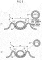
- Figure 5 is an enlarged sectional view of essential portions of the first gas cooler 4 and the second gas cooler 5 in Embodiment 1.
- (1) shows the first gas cooler 4.
- (2) shows the second gas cooler 5.
- the first twist pipe 41 and the first refrigerant heat transfer pipe 42 are joined with a heat transfer material 60 such as solder.
- the second gas cooler 5 includes a second twist pipe 51 and a second refrigerant heat transfer pipe 52.
- the second twist pipe 51 has a helical groove 511 in an outer periphery thereof.
- the second refrigerant heat transfer pipe 52 forms a second refrigerant heat transfer channel
- the second twist pipe 51 forms a second liquid heat transfer channel.
- Figure 5 shows a section in a longitudinal direction of the first twist pipe 41 or the second twist pipe 51.
- a sectional shape of the first refrigerant heat transfer pipe 42 or the second refrigerant heat transfer pipe 52 after being wound is not a circle, but is a flat or elliptical shape with a long side in an axial direction of the first twist pipe 41 or the second twist pipe 51.
- An inner diameter di1 of the first refrigerant heat transfer pipe 42 or an inner diameter di2 of the second refrigerant heat transfer pipe 52 herein refer to an inner diameter of a circular state before the refrigerant heat transfer pipe is wound around the first twist pipe 41 or the second twist pipe 51.
- an end of the first refrigerant heat transfer pipe 42 or the second refrigerant heat transfer pipe 52 is not wound around the first twist pipe 41 or the second twist pipe 51.
- the inner diameter di1 of the first refrigerant heat transfer pipe 42 or the inner diameter di2 of the second refrigerant heat transfer pipe 52 before being wound around the first twist pipe 41 or the second twist pipe 51 may be measured.
- the first refrigerant heat transfer pipe 42 or the second refrigerant heat transfer pipe 52 wound around the first twist pipe 41 or the second twist pipe 51 may be regarded to have an elliptical shape, and an average value of a long diameter and a short diameter of the ellipse may be used as the inner diameter di1 of the first refrigerant heat transfer pipe 42 or the inner diameter di2 of the second refrigerant heat transfer pipe 52.
- the inner diameter di1 of the first refrigerant heat transfer pipe 42 in the first gas cooler 4 is desirably larger than the inner diameter di2 of the second refrigerant heat transfer pipe 52 in the second gas cooler 5.
- a twist pitch p of the first twist pipe 41 in the first gas cooler 4 is desirably larger than a twist pitch p2 of the second twist pipe 51 in the second gas cooler 5.
- the twist pitch p of the first twist pipe 41 in the first gas cooler 4 and the twist pitch p2 of the second twist pipe 51 in the second gas cooler 5 are herein defined as lengths of portions in Figure 5 .
- the twist pitch p of the first twist pipe 41 is a distance between centers of two peaks with the groove 411 therebetween in a section in a longitudinal direction of the first twist pipe 41.
- the twist pitch p2 of the second twist pipe 51 is a distance between centers of two peaks with the groove 511 therebetween in a section in a longitudinal direction of the second twist pipe 51.
- the number of the first refrigerant heat transfer channel(s) in the first gas cooler 4 is equal to the number of the second refrigerant heat transfer channel(s) in the second gas cooler 5.
- Figure 6 shows temperature changes of the refrigerant and water in the first gas cooler 4 and the second gas cooler 5 as a whole, and a split position between the first gas cooler 4 and the second gas cooler 5.
- the axis of abscissa in Figure 6 represents a ratio to a total length of the first twist pipe 41 and the second twist pipe 51 (that is, a sum of lengths of the first liquid heat transfer channel and the second liquid heat transfer channel).
- An origin (0) on the axis of abscissa in Figure 6 represents a water outlet and a refrigerant inlet of the first gas cooler 4, and a right end (1) on the axis of abscissa represents a water inlet and a refrigerant outlet of the second gas cooler 5.
- a large amount of refrigerator oil together with the refrigerant gas is circulated in the first refrigerant heat transfer pipe 42 in the first gas cooler 4.
- hot refrigerator oil is also subjected to heat exchange with water.
- Specific heat of the refrigerator oil being lower than specific heat of the refrigerant gas may cause a reduction in heating capability and a resulting reduction in hot-water supply efficiency.
- the specific heat of the refrigerant gas significantly increases at a temperature of 20°C to 60°C, while the specific heat of the refrigerator oil is substantially constant irrespective of the temperature.
- the refrigerant gas In order to prevent a reduction in heating capability due to the refrigerant gas containing a large amount of refrigerator oil, the refrigerant gas needs to contain little refrigerator oil in a temperature zone with a significant increase in specific heat of the refrigerant gas. As shown in Figure 6 , a temperature of a pinch point at which temperatures of the refrigerant gas and water are closest is about 50°C. Thus, an upper limit temperature in a range with a rapid increase in specific heat of the refrigerant gas is about the temperature at the pinch point plus 10°C.
- an outlet temperature ( ⁇ a temperature of the second intake passage 36) of the first refrigerant heat transfer pipe 42 in the first gas cooler 4 is 10°C or more higher than the temperature at the pinch point, a reduction in heating capability can be prevented. If the outlet temperature of the first refrigerant heat transfer pipe 42 in the first gas cooler 4 is at least higher than the temperature at the pinch point, a significant reduction in heating capability can be prevented.
- the split position between the first gas cooler 4 and the second gas cooler 5 is desirably on a high temperature side of the pinch point at which the temperatures of the refrigerant gas and water are closest.
- the length of the first twist pipe 41 in the first gas cooler 4 is desirably about 10% on the high temperature side of the total length of the first twist pipe 41 and the second twist pipe 51.
- Figure 7 shows density change of the refrigerant in the first gas cooler 4 and the second gas cooler 5 as a whole.
- the axis of abscissa in Figure 7 refers to the same as the axis of abscissa in Figure 6 .
- the refrigerant at higher temperature has a lower density.
- Pressure loss ⁇ P of the refrigerant in the refrigerant heat transfer pipe is expressed by the following expression 1.
- the sectional shape of the refrigerant heat transfer pipe is a circle for simplicity of description.
- ⁇ P ⁇ / di ⁇ ⁇ / 2 ⁇ u 2 ⁇ L
- ⁇ is a pipe friction coefficient
- di [m] is an inner diameter of the refrigerant heat transfer pipe
- p [kg/m 3 ] is a refrigerant density
- u [m/s] is a refrigerant flow speed
- L [m] is a channel length.
- the shapes and the refrigerant flow rates of the first refrigerant heat transfer pipe 42 and the second refrigerant heat transfer pipe 52 are constant, and the pipe friction coefficient ⁇ does not change. From the above expression, the refrigerant pressure loss ⁇ P per unit channel length is proportional to 1/ ⁇ .
- the refrigerant gas containing the large amount of refrigerator oil is circulated to the first gas cooler 4, and the refrigerant gas containing only the small amount of refrigerator oil is circulated to the second gas cooler 5.
- a viscosity of a CO 2 gas refrigerant in the first gas cooler 4 is 1, an average viscosity ratio of the refrigerator oil is 311.
- the refrigerator oil has a significantly higher viscosity than the CO 2 gas refrigerant. This increases pressure loss of the refrigerant gas containing the large amount of refrigerator oil.
- the mass flow rate of the refrigerator oil is Goil [kg/s].
- the oil circulation rate OC is a ratio of the mass flow rate of the refrigerator oil with respect to a sum of the mass flow rate of the refrigerant and the mass flow rate of the refrigerator oil.
- the oil circulation rate OC of the first gas cooler 4 is preferably not less than 2%, and more preferably not less than 5%.
- the oil circulation rate OC of the first gas cooler 4 is preferably not more than 20%, and more preferably not more than 10%. Setting the oil circulation rate OC of the first gas cooler 4 to the above-described lower limit value or more allows heat from the hot refrigerator oil in the compressor 3 to be effectively used for heating water in the first gas cooler 4, improving heating capability. Setting the oil circulation rate OC of the first gas cooler 4 to the above-described upper limit value or less can reliably reduce the refrigerant pressure loss of the first gas cooler 4, and also reliably prevent an excessive reduction in the amount of the refrigerator oil in the compressor 3.
- the oil circulation rate OC of the second gas cooler 5 is preferably not less than 0.01%, and more preferably not less than 0.1%. In the rated operation state of the heat pump device 1, the oil circulation rate OC of the second gas cooler 5 is preferably not more than 1%, and more preferably not more than 0.5%. Setting the oil circulation rate OC of the second gas cooler 5 to the above-described upper limit value or less can reliably reduce the refrigerant pressure loss of the second gas cooler 5.
- the refrigerator oil has little influence, and there is no need to further reduce the oil circulation rate OC of the second gas cooler 5 to be lower than the above-described lower limit value.
- the oil circulation rate OC of the second gas cooler 5 may be lower than the above-described lower limit value.
- the refrigerant pressure loss is about 1.6 to 2.0 times larger than that when the oil circulation rate OC is 0.5% or less under the same other conditions.
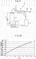
- Figure 8 shows ratios of refrigerant pressure losses of the first gas cooler 4 and the second gas cooler 5 in a case where the first gas cooler 4 and the second gas cooler 5 have the same shape other than their channel lengths.
- Figure 9 is a configuration diagram of a conventional heat pump device. First, a conventional heat pump device 70 in Figure 9 will be described. Components common with those of the heat pump device 1 according to Embodiment 1 are denoted by the same reference numerals and overlapping descriptions will be omitted.
- the heat pump device 70 in Figure 9 includes a compressor 71 having one intake passage and one discharge passage instead of the compressor 3 in the heat pump device 1 according to Embodiment 1.
- the heat pump device 70 includes a single gas cooler 72 instead of the first gas cooler 4 and the second gas cooler 5.
- the case of "0.5% OR LESS IN OVERALL GAS COOLER(S)" in Figure 8 refers to a case where, as in the conventional heat pump device 70 in Figure 9 , the gas cooler 72 is not split into the first gas cooler 4 and the second gas cooler 5, and the refrigerant from which the refrigerator oil is separated in the sealed container of the compressor 71 is caused to flow into the gas cooler 72. Specifically, this refers to a case of a conventional refrigeration cycle where the refrigerant is not returned into the sealed container 31 of the compressor 3 between the first gas cooler 4 and the second gas cooler 5.
- a ratio of the refrigerant pressure loss of a portion corresponding to a channel length of 10% on a refrigerant high temperature side of a total channel length of the gas cooler 72 is 0.17.
- the ratio of the refrigerant pressure loss of a remaining portion corresponding to a channel length of 90% on a refrigerant low temperature side is 0.83.
- the refrigerant density is low, and thus the ratio of the refrigerant pressure loss of the portion corresponding to the channel length of 10% of the total channel length is 17% of the total refrigerant pressure loss, and higher than the ratio of the channel length.
- the refrigerant pressure loss of the overall gas coolers is significantly influenced.
- the refrigerant pressure loss of the overall gas coolers is 1.17 times as compared to a case with a low oil circulation rate as a whole.
- the ratio of the refrigerant pressure loss of the first gas cooler 4 with respect to the overall gas coolers is 29% and high.
- the first gas cooler 4 has a higher oil circulation rate than the second gas cooler 5, mainly flowing medium is the refrigerant.
- the heat exchanger constituting the first gas cooler 4 preferably has a configuration of a general heat exchanger for a refrigerant rather than of an oil cooler type heat exchanger.
- the first gas cooler 4 preferably uses a twist pipe like the second gas cooler 5.
- the high oil circulation rate of the first gas cooler 4 easily increases the refrigerant pressure loss of the first gas cooler 4, and increases discharge pressure of the compressor 3. This easily increases input power for the compressor 3 and reduces the COP.
- the refrigerant pressure loss of the first gas cooler 4 is reduced as described below.
- the refrigerant pressure loss ⁇ P in the first refrigerant heat transfer pipe 42 has the following proportional relationship from the expressions 1 to 3 above, with a pipe friction coefficient, a refrigerant density, and a refrigerant flow rate being constant. ⁇ P ⁇ L / di 1 5
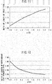
- Figure 10 shows a relationship between a ratio of the twist pitch p to the inner diameter SRi of the first twist pipe 41 and a heat transfer coefficient on water side.
- Figure 10 shows change in heat transfer coefficient on water side with a constant inner diameter SRi and an increased twist pitch p of the first twist pipe 41.
- the heat transfer coefficient on water side is represented by a ratio to the heat transfer coefficient on water side when p/SRi is 1.
- the heat transfer coefficient on water side increases.
- Figure 11 shows a relationship between the ratio of the twist pitch p to the inner diameter SRi of the first twist pipe 41 and a required length of the first twist pipe 41.
- a length of the first twist pipe 41 required, when the twist pitch p is increased with a constant inner diameter SRi of the first twist pipe 41, for obtaining an equal amount of heat exchange is represented by a ratio to a reference length.
- the first gas cooler 4 as a twist pipe type heat exchanger is configured so that the first refrigerant heat transfer pipe 42 is wound along the helical groove 411 in the first twist pipe 41.
- Figure 12 shows a relationship between the ratio of the twist pitch p to the inner diameter SRi of the first twist pipe 41 and a required length of the first refrigerant heat transfer pipe 42.
- the length of the first refrigerant heat transfer pipe 42 required, when the twist pitch p is increased with a constant inner diameter SRi of the first twist pipe 41, for obtaining an equal amount of heat exchange is represented by a ratio to the length of the first refrigerant heat transfer pipe 42 required at p/SRi of 1.
- a required length of the first twist pipe 41 is increased.
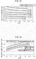
- Figure 13 shows a relationship among the refrigerant pressure loss of the first gas cooler 4, the ratio of the twist pitch p to the inner diameter SRi of the first twist pipe 41, and the inner diameter di1 of the first refrigerant heat transfer pipe 42.
- a ratio di1/di2 of the inner diameter di1 of the first refrigerant heat transfer pipe 42 in the first gas cooler 4 to the inner diameter di2 of the second refrigerant heat transfer pipe 52 in the second gas cooler is referred to as "an inner diameter ratio”.
- Figure 13 shows changes in refrigerant pressure loss of the first gas cooler 4 when the twist pitch p of the first twist pipe 41 is changed for each of cases where the inner diameter ratio di1/di2 is set to a plurality of values in Figure 13 with a constant amount of heat exchange in the first gas cooler 4.
- the refrigerant pressure loss of the first gas cooler 4 is represented by a ratio to the refrigerant pressure loss of the first gas cooler 4 when values of the inner diameter ratio di1/di2 and p/SRi are both 1.
- Figure 14 shows a relationship between the ratio of the twist pitch p to the inner diameter SRi of the first twist pipe 41 in the first gas cooler 4 and the length of the first twist pipe 41 in each of the cases in Figure 13 .
- the length of the first twist pipe 41 is represented by a ratio to the length of the first twist pipe 41 when the values of the inner diameter ratio di1/di2 and p/SRi are both 1.
- the ratio of the twist pitch p2 to the inner diameter SRi of the second twist pipe 51 in the second gas cooler 5 is about 1.
- the inner diameter SRi of the first twist pipe 41 in the first gas cooler 4 is equal to the inner diameter SRi of the second twist pipe 51 in the second gas cooler 5.
- a size of the overall gas coolers including the first gas cooler 4 and the second gas cooler 5 may be increased to increase a size of a casing of the heat pump device 1.
- an amount of material required for the first twist pipe 41 is increased to increase weight and cost.
- an amount of heat dissipation from the first gas cooler 4 out of the heat pump device 1 may be increased or the pressure loss on water side may be increased.
- p/SRi as the ratio of the twist pitch p to the inner diameter SRi of the first twist pipe 41 is desirably not more than 1.8. As described above, in the region at p/SRi of more than 1.8, the required length of the first refrigerant heat transfer pipe 42 is less likely to be reduced by increasing the twist pitch p of the first twist pipe 41.
- p/SRi of the first twist pipe 41 in the first gas cooler 4 is preferably not less than 1.1, more preferably not less than 1.2, and further preferably not less than 1.4. Setting p/SRi to preferably 1.1 or more, more preferably 1.2 or more, and further preferably 1.4 or more can effectively reduce the length of the first refrigerant heat transfer pipe 42 (see Figure 12 ). This can more reliably reduce the refrigerant pressure loss of the first gas cooler 4.
- p/SRi of the first twist pipe 41 in the first gas cooler 4 is preferably not less than 1.1 and not more than 1.8, more preferably not less than 1.2 and not more than 1.8, and further preferably not less than 1.4 and not more than 1.8.
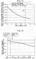
- Figure 15 shows change in the refrigerant pressure loss of the first gas cooler 4 when the inner diameter ratio di1/di2 of the first refrigerant heat transfer pipe 42 and the second refrigerant heat transfer pipe 52 is changed at p/SRi of 1.8 of the first twist pipe 41.
- the refrigerant pressure loss of the first gas cooler 4 is represented by a ratio to a sum of the refrigerant pressure loss of the first gas cooler 4 and the refrigerant pressure loss of the second gas cooler 5 (that is, the refrigerant pressure loss of the overall gas coolers).
- an inner diameter di1 of the first refrigerant heat transfer pipe 42 may reduce the refrigerant flow speed, thereby reducing flowage of the refrigerator oil. This may significantly increase retention of refrigerator oil in the first gas cooler 4. For these reasons, it is desirable to set the inner diameter ratio di1 of the first refrigerant heat transfer pipe 42 in the first gas cooler to a value that is not too large.
- the channel length of the first gas cooler 4 is about 10% of the channel length of the overall gas coolers.
- the ratio of the refrigerant pressure loss of the first gas cooler 4 with respect to the refrigerant pressure loss of the overall gas coolers can be reduced to about 10%, it can be said that the refrigerant pressure loss of the first gas cooler 4 is sufficiently reduced. It can be also said that further reducing the refrigerant pressure loss of the first gas cooler 4, that is, reducing the refrigerant pressure loss per unit channel length in the first gas cooler 4 to be smaller than the refrigerant pressure loss per unit channel length in the second gas cooler 5 is an excess.
- the ratio of the refrigerant pressure loss of the first gas cooler 4 with respect to the refrigerant pressure loss of the overall gas coolers is about 10%.
- setting the value of the inner diameter ratio di1/di2 to 1.4 sufficiently reduces the refrigerant pressure loss of the first gas cooler 4 in the relationship with the ratio of the channel length.
- too large a value of the inner diameter ratio di1/di2 that is, too large an inner diameter di1 of the first refrigerant heat transfer pipe 42 may cause the negative effects as described above such as an excessive length of the first twist pipe 41 or an increase in the retention of refrigerator oil in the first gas cooler 4.
- the value of the inner diameter ratio di1/di2 of 1.4 or less the inner diameter di1 of the first refrigerant heat transfer pipe 42 is not too large, thereby reliably preventing the negative effects.
- the value of the inner diameter ratio di1/di2 of the first refrigerant heat transfer pipe 42 and the second refrigerant heat transfer pipe 52 is preferably not less than 1.1, and more preferably not less than 1.2. Setting the value of the inner diameter ratio di1/di2 to preferably 1.1 or more, and more preferably 1.2 or more can more reliably reduce the refrigerant pressure loss of the first gas cooler 4 (see Figure 13 ). In short, the value of the inner diameter ratio di1/di2 is preferably not less than 1.1 and not more than 1.4, and more preferably not less than 1.2 and not more than 1.4.
- the refrigerant pressure loss of the first gas cooler 4 can be reliably prevented to reduce input power for the compressor 3 and improve a COP.
- the refrigerant density in the second gas cooler 5 is higher than the refrigerant density in the first gas cooler 4.
- the refrigerant pressure loss per unit channel length is reduced.
- the refrigerant pressure loss per unit length of the second refrigerant heat transfer pipe 52 in the second gas cooler 5 is smaller than the refrigerant pressure loss per unit length of the first refrigerant heat transfer pipe 42 in the first gas cooler 4.
- the refrigerant pressure loss of the second gas cooler 5 can be sufficiently reduced.
- the inner diameter di2 of the second refrigerant heat transfer pipe 52 or the sectional area of each second refrigerant heat transfer channel in the second gas cooler 5 being relatively small increases the refrigerant flow speed in the second refrigerant heat transfer pipe 52, that is, in each second refrigerant heat transfer channel, thereby increasing a heat transfer coefficient of the refrigerant.
- the inner diameter di1 of the first refrigerant heat transfer pipe 42 or the sectional area of each first refrigerant heat transfer channel in the first gas cooler 4 is preferably larger than the inner diameter di2 of the second refrigerant heat transfer pipe 52 or the sectional area of each second refrigerant heat transfer channel in the second gas cooler 5.
- Figure 16 shows change in heat transfer coefficient on water side in a case where the twist pitch p of the first twist pipe 41 is equal to the twist pitch p2 of the second twist pipe 51 and the inner diameters SRi of the first twist pipe 41 and the second twist pipe 51 are equal.
- the axis of abscissa in Figure 16 refers to the same as the axis of abscissa in Figure 6 .
- the heat transfer coefficient on water side is represented by a ratio to the heat transfer coefficient on water side at the water outlet of the first gas cooler 4. As shown in Figure 16 , with increasing distance from the refrigerant inlet and the water outlet of the first gas cooler 4, that is, with decreasing temperature of water, the heat transfer coefficient on water side is reduced.
- the twist pitch p of the first twist pipe 41 is equal to the twist pitch p2 of the second twist pipe 51, and the inner diameters SRi of the first twist pipe 41 and the second twist pipe 51 are equal, the heat transfer coefficient on water side in the second gas cooler 5 is lower than the heat transfer coefficient on water side in the first gas cooler 4.
- the twist pitch p of the first twist pipe 41 in the first gas cooler 4 is desirably relatively large. From the above, the twist pitch p of the first twist pipe 41 in the first gas cooler 4 is preferably larger than the twist pitch p2 of the second twist pipe 51 in the second gas cooler 5.
- the inner diameter SRi of the first twist pipe 41 in the first gas cooler 4 is preferably equal to the inner diameter SRi of the second twist pipe 51 in the second gas cooler 5. If the second gas cooler 5 is placed near the first gas cooler 4, an upstream end of the first twist pipe 41 is connected to a downstream end of the second twist pipe 51.
- the inner diameter SRi of the first twist pipe 41 being equal to the inner diameter SRi of the second twist pipe 51 allows easy connection between the first twist pipe 41 and the second twist pipe 51.
- the inner diameter SRi of the first twist pipe 41 being equal to the inner diameter SRi of the second twist pipe 51 allows material and a manufacturing method used for the first twist pipe 41 and the second twist pipe 51 to be shared, thereby reducing cost.
- the number of the first refrigerant heat transfer pipe(s) 42 is preferably equal to the number of the second refrigerant heat transfer pipe(s) 52, that is, the number of the second refrigerant heat transfer channel(s) in the second gas cooler 5.
- the number of the first refrigerant heat transfer pipe(s) 42 being equal to the number of the second refrigerant heat transfer pipe(s) 52 allows the first twist pipe 41 and the second twist pipe 51 to be similarly designed, thereby reducing cost.
- first heat exchanger first gas cooler 4
- second heat exchanger second gas cooler 5
- first heat exchanger and the second heat exchanger are not limited to the twist pipe type heat exchanger, but various types of heat exchangers may be used.
- the value of the inner diameter ratio di1/di2 of the first refrigerant heat transfer pipe 42 and the second refrigerant heat transfer pipe 52 is preferably not less than 1.1 and not more than 1.4, and more preferably not less than 1.2 and not more than 1.4. If the inner diameter ratio di1/di2 is 1.1, the ratio of the total sectional area of the first refrigerant heat transfer channels in the first heat exchanger to the total sectional area of the second refrigerant heat transfer channels in the second heat exchanger is (11.1) 2 ⁇ 1.2.
- the ratio of the total sectional area of the first refrigerant heat transfer channels in the first heat exchanger to the total sectional area of the second refrigerant heat transfer channels in the second heat exchanger is (1.2) 2 ⁇ 1.4. If the inner diameter ratio di1/di2 is 1.4, the ratio of the total sectional area of the first refrigerant heat transfer channels in the first heat exchanger to the total sectional area of the second refrigerant heat transfer channels in the second heat exchanger is (1.4) 2 ⁇ 2.
- the ratio of the total sectional area of the first refrigerant heat transfer channels to the total sectional area of the second refrigerant heat transfer channels is preferably not less than 1.2 and not more than 2, and more preferably not less than 1.4 and not more than 2.
- the ratio of the channel sectional area within such a range provides advantages similar to those described above.
- the number of the first refrigerant heat transfer channels in the first heat exchanger (first gas cooler 4) is equal to the number of the second refrigerant heat transfer channels in the second heat exchanger (second gas cooler 5) has been mainly described, however, in the present invention, the number of the first refrigerant heat transfer channels may be larger than the number of the second refrigerant heat transfer channel(s). If the number of the first refrigerant heat transfer channels is larger than the number of the second refrigerant heat transfer channel(s), the total sectional area of the first refrigerant heat transfer channels can be larger than the total sectional area of the second refrigerant heat transfer channels with a simple configuration.
- the sectional area of the first refrigerant heat transfer channel may be equal to the sectional area of the second refrigerant heat transfer channel. This allows the first refrigerant heat transfer pipe 42 in the first gas cooler 4 and the second refrigerant heat transfer pipe 52 in the second gas cooler 5 to be made of a common material, thereby reducing cost.
- the heat pump device for heating water using the first heat exchanger and the second heat exchanger has been described as an example, but in the present invention, the liquid heated by the first heat exchanger and the second heat exchanger is not limited to water, but for example, may be brine, antifreeze liquid, or the like.
Landscapes
- Engineering & Computer Science (AREA)
- Mechanical Engineering (AREA)
- General Engineering & Computer Science (AREA)
- Physics & Mathematics (AREA)
- Thermal Sciences (AREA)
- Geometry (AREA)
- Heat-Pump Type And Storage Water Heaters (AREA)
- Heat-Exchange Devices With Radiators And Conduit Assemblies (AREA)
Applications Claiming Priority (1)
| Application Number | Priority Date | Filing Date | Title |
|---|---|---|---|
| PCT/JP2013/066313 WO2014199479A1 (ja) | 2013-06-13 | 2013-06-13 | ヒートポンプ装置 |
Publications (3)
| Publication Number | Publication Date |
|---|---|
| EP3009767A1 true EP3009767A1 (de) | 2016-04-20 |
| EP3009767A4 EP3009767A4 (de) | 2017-01-25 |
| EP3009767B1 EP3009767B1 (de) | 2020-12-09 |
Family
ID=52021810
Family Applications (1)
| Application Number | Title | Priority Date | Filing Date |
|---|---|---|---|
| EP13886812.0A Not-in-force EP3009767B1 (de) | 2013-06-13 | 2013-06-13 | Wärmepumpenvorrichtung |
Country Status (3)
| Country | Link |
|---|---|
| EP (1) | EP3009767B1 (de) |
| JP (1) | JP6075451B2 (de) |
| WO (1) | WO2014199479A1 (de) |
Cited By (3)
| Publication number | Priority date | Publication date | Assignee | Title |
|---|---|---|---|---|
| EP3370026A4 (de) * | 2017-01-18 | 2018-09-05 | Mitsubishi Electric Corporation | Spiralwärmetauscher |
| EP3581868A1 (de) * | 2018-06-15 | 2019-12-18 | Mitsubishi Heavy Industries Thermal Systems, Ltd. | Wasserwärmetauscher und gaskühler |
| EP3671049A1 (de) * | 2018-12-17 | 2020-06-24 | Panasonic Intellectual Property Management Co., Ltd. | Wärmepumpensystem |
Families Citing this family (1)
| Publication number | Priority date | Publication date | Assignee | Title |
|---|---|---|---|---|
| WO2016147389A1 (ja) * | 2015-03-19 | 2016-09-22 | 三菱電機株式会社 | ヒートポンプシステム |
Family Cites Families (23)
| Publication number | Priority date | Publication date | Assignee | Title |
|---|---|---|---|---|
| JPS512325Y1 (de) * | 1970-11-07 | 1976-01-23 | ||
| JPS5224805Y2 (de) * | 1971-10-05 | 1977-06-06 | ||
| JPS512325B2 (de) * | 1971-11-19 | 1976-01-24 | ||
| JP3477531B1 (ja) * | 2002-07-04 | 2003-12-10 | 太平洋精工株式会社 | 熱交換器及びその製造方法、並びに、かかる熱交換器を用いる風呂湯沸かしシステム及び床暖房システム |
| JP3877207B2 (ja) * | 2002-09-13 | 2007-02-07 | 株式会社前川製作所 | Co2冷凍サイクルの給湯システム |
| JP2004205077A (ja) * | 2002-12-24 | 2004-07-22 | Sapporo Holdings Ltd | 偏平管を使用した液体冷却用の冷却装置および該冷却装置を用いた液体冷却供給装置。 |
| JP2010091266A (ja) * | 2004-08-26 | 2010-04-22 | Mitsubishi Electric Corp | 捩り管形熱交換器 |
| JP4449856B2 (ja) * | 2004-08-26 | 2010-04-14 | 三菱電機株式会社 | 捩り管形熱交換器 |
| JP4434924B2 (ja) * | 2004-11-05 | 2010-03-17 | 三菱電機株式会社 | 圧縮機及び給湯サイクル装置 |
| JP4200329B2 (ja) * | 2005-06-06 | 2008-12-24 | パナソニック株式会社 | 熱交換装置及びそれを用いたヒートポンプ給湯装置 |
| JP2008190787A (ja) * | 2007-02-05 | 2008-08-21 | Furukawa Electric Co Ltd:The | スパイラル管およびこれを用いた熱交換器 |
| JP2008241217A (ja) * | 2007-03-29 | 2008-10-09 | Mitsubishi Electric Corp | 熱交換器の製造方法及びこの製造方法によって製造した熱交換器 |
| JP2008309361A (ja) * | 2007-06-12 | 2008-12-25 | Panasonic Corp | 冷凍サイクル装置 |
| JP2009041880A (ja) * | 2007-08-10 | 2009-02-26 | Sumitomo Light Metal Ind Ltd | 給湯機用水熱交換器 |
| JP4819765B2 (ja) * | 2007-08-22 | 2011-11-24 | 三菱電機株式会社 | 捩り管形熱交換器の製造方法 |
| JP4713562B2 (ja) * | 2007-11-21 | 2011-06-29 | 三菱電機株式会社 | 熱交換器及びこれを用いたヒートポンプ式給湯機 |
| JP5171280B2 (ja) * | 2008-01-18 | 2013-03-27 | 日立アプライアンス株式会社 | 熱交換器及びそれを用いたヒートポンプ式給湯機 |
| JP5293584B2 (ja) * | 2009-12-14 | 2013-09-18 | 三菱電機株式会社 | 捩り管形熱交換器および捩り管形熱交換器の製造方法 |
| JP4941581B2 (ja) * | 2010-07-15 | 2012-05-30 | ダイキン工業株式会社 | ヒートポンプシステム |
| JP5404589B2 (ja) * | 2010-12-09 | 2014-02-05 | 三菱電機株式会社 | 捩り管形熱交換器 |
| JP5656786B2 (ja) * | 2011-09-22 | 2015-01-21 | 三菱電機株式会社 | 異径捩り管形熱交換器の製造方法 |
| JP2013088045A (ja) * | 2011-10-19 | 2013-05-13 | Hitachi Appliances Inc | 熱交換器及びそれを用いたヒートポンプ式給湯機 |
| JP5794952B2 (ja) * | 2012-06-13 | 2015-10-14 | 三菱電機株式会社 | 捩り管形熱交換器 |
-
2013
- 2013-06-13 EP EP13886812.0A patent/EP3009767B1/de not_active Not-in-force
- 2013-06-13 JP JP2015522338A patent/JP6075451B2/ja not_active Expired - Fee Related
- 2013-06-13 WO PCT/JP2013/066313 patent/WO2014199479A1/ja not_active Ceased
Non-Patent Citations (1)
| Title |
|---|
| See references of WO2014199479A1 * |
Cited By (3)
| Publication number | Priority date | Publication date | Assignee | Title |
|---|---|---|---|---|
| EP3370026A4 (de) * | 2017-01-18 | 2018-09-05 | Mitsubishi Electric Corporation | Spiralwärmetauscher |
| EP3581868A1 (de) * | 2018-06-15 | 2019-12-18 | Mitsubishi Heavy Industries Thermal Systems, Ltd. | Wasserwärmetauscher und gaskühler |
| EP3671049A1 (de) * | 2018-12-17 | 2020-06-24 | Panasonic Intellectual Property Management Co., Ltd. | Wärmepumpensystem |
Also Published As
| Publication number | Publication date |
|---|---|
| EP3009767B1 (de) | 2020-12-09 |
| JPWO2014199479A1 (ja) | 2017-02-23 |
| EP3009767A4 (de) | 2017-01-25 |
| JP6075451B2 (ja) | 2017-02-08 |
| WO2014199479A1 (ja) | 2014-12-18 |
Similar Documents
| Publication | Publication Date | Title |
|---|---|---|
| US20130089413A1 (en) | Screw Compressor | |
| EP3009767B1 (de) | Wärmepumpenvorrichtung | |
| US20090250198A1 (en) | Hot water corrugated heat transfer tube | |
| CN106907950B (zh) | 溢流式蒸发器内的侧装式制冷剂分配器和分配器的侧装式输入管道 | |
| US20180238561A1 (en) | Heat pump water heater | |
| JP6687022B2 (ja) | 冷凍サイクル装置 | |
| US8215380B2 (en) | Hot water heat transfer pipe | |
| EP2930449B1 (de) | Verdichter, kältekreislaufvorrichtung und heisswasserzufuhrvorrichtung für eine wärmepumpe | |
| JP7565358B2 (ja) | ハイブリッド冷却システム、密閉型モータ、及び/又は、暖房、換気、空調、および冷房(hvac&r)システム | |
| US10677246B2 (en) | Variable volume ratio compressor | |
| US4307578A (en) | Heat exchanger efficiently operable alternatively as evaporator or condenser | |
| EP2927622B1 (de) | Verdichter, kältekreislaufvorrichtung und heisswasserzufuhrvorrichtung für eine wärmepumpe | |
| JP4063237B2 (ja) | 熱交換装置及びそれを用いたヒートポンプ給湯装置 | |
| US4524822A (en) | Safety heat-transmitting device | |
| US10436219B2 (en) | Fins, tubes, and structures for fin array for use in a centrifugal fan | |
| JP2006336988A (ja) | 熱交換装置及びそれを用いたヒートポンプ給湯装置 | |
| CN110411245A (zh) | 盘管式换热设备和空调系统 | |
| JP5333041B2 (ja) | 熱交換器及びそれを備えた冷凍装置 | |
| KR20200093327A (ko) | 전열관 및 칠러용 열교환기 | |
| JP5566001B2 (ja) | 二酸化炭素冷媒を使用したガスクーラー用内面溝付伝熱管 | |
| JP5892261B2 (ja) | 冷凍サイクル装置およびヒートポンプ給湯装置 | |
| JP4200323B2 (ja) | 熱交換装置及びそれを用いたヒートポンプ給湯装置 | |
| US20250224162A1 (en) | Inline refrigerant mixer for thermostatic expansion valve bulb associated with refrigeration circuits and heat exchangers | |
| JP2013088045A (ja) | 熱交換器及びそれを用いたヒートポンプ式給湯機 | |
| CN118974493A (zh) | 热泵 |
Legal Events
| Date | Code | Title | Description |
|---|---|---|---|
| PUAI | Public reference made under article 153(3) epc to a published international application that has entered the european phase |
Free format text: ORIGINAL CODE: 0009012 |
|
| 17P | Request for examination filed |
Effective date: 20151113 |
|
| AK | Designated contracting states |
Kind code of ref document: A1 Designated state(s): AL AT BE BG CH CY CZ DE DK EE ES FI FR GB GR HR HU IE IS IT LI LT LU LV MC MK MT NL NO PL PT RO RS SE SI SK SM TR |
|
| AX | Request for extension of the european patent |
Extension state: BA ME |
|
| DAX | Request for extension of the european patent (deleted) | ||
| A4 | Supplementary search report drawn up and despatched |
Effective date: 20161222 |
|
| RIC1 | Information provided on ipc code assigned before grant |
Ipc: F25B 6/04 20060101AFI20161216BHEP Ipc: F28D 7/02 20060101ALI20161216BHEP Ipc: F25B 40/00 20060101ALI20161216BHEP Ipc: F04C 23/00 20060101ALI20161216BHEP Ipc: F04C 29/04 20060101ALI20161216BHEP Ipc: F25B 30/02 20060101ALI20161216BHEP Ipc: F04B 39/06 20060101ALI20161216BHEP |
|
| GRAP | Despatch of communication of intention to grant a patent |
Free format text: ORIGINAL CODE: EPIDOSNIGR1 |
|
| STAA | Information on the status of an ep patent application or granted ep patent |
Free format text: STATUS: GRANT OF PATENT IS INTENDED |
|
| INTG | Intention to grant announced |
Effective date: 20200729 |
|
| GRAS | Grant fee paid |
Free format text: ORIGINAL CODE: EPIDOSNIGR3 |
|
| GRAA | (expected) grant |
Free format text: ORIGINAL CODE: 0009210 |
|
| STAA | Information on the status of an ep patent application or granted ep patent |
Free format text: STATUS: THE PATENT HAS BEEN GRANTED |
|
| AK | Designated contracting states |
Kind code of ref document: B1 Designated state(s): AL AT BE BG CH CY CZ DE DK EE ES FI FR GB GR HR HU IE IS IT LI LT LU LV MC MK MT NL NO PL PT RO RS SE SI SK SM TR |
|
| REG | Reference to a national code |
Ref country code: GB Ref legal event code: FG4D |
|
| REG | Reference to a national code |
Ref country code: AT Ref legal event code: REF Ref document number: 1343857 Country of ref document: AT Kind code of ref document: T Effective date: 20201215 Ref country code: CH Ref legal event code: EP |
|
| REG | Reference to a national code |
Ref country code: DE Ref legal event code: R096 Ref document number: 602013074689 Country of ref document: DE |
|
| REG | Reference to a national code |
Ref country code: IE Ref legal event code: FG4D |
|
| PG25 | Lapsed in a contracting state [announced via postgrant information from national office to epo] |
Ref country code: NO Free format text: LAPSE BECAUSE OF FAILURE TO SUBMIT A TRANSLATION OF THE DESCRIPTION OR TO PAY THE FEE WITHIN THE PRESCRIBED TIME-LIMIT Effective date: 20210309 Ref country code: RS Free format text: LAPSE BECAUSE OF FAILURE TO SUBMIT A TRANSLATION OF THE DESCRIPTION OR TO PAY THE FEE WITHIN THE PRESCRIBED TIME-LIMIT Effective date: 20201209 Ref country code: FI Free format text: LAPSE BECAUSE OF FAILURE TO SUBMIT A TRANSLATION OF THE DESCRIPTION OR TO PAY THE FEE WITHIN THE PRESCRIBED TIME-LIMIT Effective date: 20201209 Ref country code: GR Free format text: LAPSE BECAUSE OF FAILURE TO SUBMIT A TRANSLATION OF THE DESCRIPTION OR TO PAY THE FEE WITHIN THE PRESCRIBED TIME-LIMIT Effective date: 20210310 |
|
| REG | Reference to a national code |
Ref country code: AT Ref legal event code: MK05 Ref document number: 1343857 Country of ref document: AT Kind code of ref document: T Effective date: 20201209 |
|
| PG25 | Lapsed in a contracting state [announced via postgrant information from national office to epo] |
Ref country code: LV Free format text: LAPSE BECAUSE OF FAILURE TO SUBMIT A TRANSLATION OF THE DESCRIPTION OR TO PAY THE FEE WITHIN THE PRESCRIBED TIME-LIMIT Effective date: 20201209 Ref country code: SE Free format text: LAPSE BECAUSE OF FAILURE TO SUBMIT A TRANSLATION OF THE DESCRIPTION OR TO PAY THE FEE WITHIN THE PRESCRIBED TIME-LIMIT Effective date: 20201209 Ref country code: BG Free format text: LAPSE BECAUSE OF FAILURE TO SUBMIT A TRANSLATION OF THE DESCRIPTION OR TO PAY THE FEE WITHIN THE PRESCRIBED TIME-LIMIT Effective date: 20210309 |
|
| REG | Reference to a national code |
Ref country code: NL Ref legal event code: MP Effective date: 20201209 |
|
| PG25 | Lapsed in a contracting state [announced via postgrant information from national office to epo] |
Ref country code: HR Free format text: LAPSE BECAUSE OF FAILURE TO SUBMIT A TRANSLATION OF THE DESCRIPTION OR TO PAY THE FEE WITHIN THE PRESCRIBED TIME-LIMIT Effective date: 20201209 Ref country code: NL Free format text: LAPSE BECAUSE OF FAILURE TO SUBMIT A TRANSLATION OF THE DESCRIPTION OR TO PAY THE FEE WITHIN THE PRESCRIBED TIME-LIMIT Effective date: 20201209 |
|
| REG | Reference to a national code |
Ref country code: LT Ref legal event code: MG9D |
|
| PG25 | Lapsed in a contracting state [announced via postgrant information from national office to epo] |
Ref country code: LT Free format text: LAPSE BECAUSE OF FAILURE TO SUBMIT A TRANSLATION OF THE DESCRIPTION OR TO PAY THE FEE WITHIN THE PRESCRIBED TIME-LIMIT Effective date: 20201209 Ref country code: SK Free format text: LAPSE BECAUSE OF FAILURE TO SUBMIT A TRANSLATION OF THE DESCRIPTION OR TO PAY THE FEE WITHIN THE PRESCRIBED TIME-LIMIT Effective date: 20201209 Ref country code: RO Free format text: LAPSE BECAUSE OF FAILURE TO SUBMIT A TRANSLATION OF THE DESCRIPTION OR TO PAY THE FEE WITHIN THE PRESCRIBED TIME-LIMIT Effective date: 20201209 Ref country code: PT Free format text: LAPSE BECAUSE OF FAILURE TO SUBMIT A TRANSLATION OF THE DESCRIPTION OR TO PAY THE FEE WITHIN THE PRESCRIBED TIME-LIMIT Effective date: 20210409 Ref country code: EE Free format text: LAPSE BECAUSE OF FAILURE TO SUBMIT A TRANSLATION OF THE DESCRIPTION OR TO PAY THE FEE WITHIN THE PRESCRIBED TIME-LIMIT Effective date: 20201209 Ref country code: CZ Free format text: LAPSE BECAUSE OF FAILURE TO SUBMIT A TRANSLATION OF THE DESCRIPTION OR TO PAY THE FEE WITHIN THE PRESCRIBED TIME-LIMIT Effective date: 20201209 Ref country code: SM Free format text: LAPSE BECAUSE OF FAILURE TO SUBMIT A TRANSLATION OF THE DESCRIPTION OR TO PAY THE FEE WITHIN THE PRESCRIBED TIME-LIMIT Effective date: 20201209 |
|
| PG25 | Lapsed in a contracting state [announced via postgrant information from national office to epo] |
Ref country code: AT Free format text: LAPSE BECAUSE OF FAILURE TO SUBMIT A TRANSLATION OF THE DESCRIPTION OR TO PAY THE FEE WITHIN THE PRESCRIBED TIME-LIMIT Effective date: 20201209 Ref country code: PL Free format text: LAPSE BECAUSE OF FAILURE TO SUBMIT A TRANSLATION OF THE DESCRIPTION OR TO PAY THE FEE WITHIN THE PRESCRIBED TIME-LIMIT Effective date: 20201209 |
|
| REG | Reference to a national code |
Ref country code: DE Ref legal event code: R097 Ref document number: 602013074689 Country of ref document: DE |
|
| PG25 | Lapsed in a contracting state [announced via postgrant information from national office to epo] |
Ref country code: IS Free format text: LAPSE BECAUSE OF FAILURE TO SUBMIT A TRANSLATION OF THE DESCRIPTION OR TO PAY THE FEE WITHIN THE PRESCRIBED TIME-LIMIT Effective date: 20210409 |
|
| PLBE | No opposition filed within time limit |
Free format text: ORIGINAL CODE: 0009261 |
|
| STAA | Information on the status of an ep patent application or granted ep patent |
Free format text: STATUS: NO OPPOSITION FILED WITHIN TIME LIMIT |
|
| PG25 | Lapsed in a contracting state [announced via postgrant information from national office to epo] |
Ref country code: AL Free format text: LAPSE BECAUSE OF FAILURE TO SUBMIT A TRANSLATION OF THE DESCRIPTION OR TO PAY THE FEE WITHIN THE PRESCRIBED TIME-LIMIT Effective date: 20201209 Ref country code: IT Free format text: LAPSE BECAUSE OF FAILURE TO SUBMIT A TRANSLATION OF THE DESCRIPTION OR TO PAY THE FEE WITHIN THE PRESCRIBED TIME-LIMIT Effective date: 20201209 |
|
| 26N | No opposition filed |
Effective date: 20210910 |
|
| PG25 | Lapsed in a contracting state [announced via postgrant information from national office to epo] |
Ref country code: ES Free format text: LAPSE BECAUSE OF FAILURE TO SUBMIT A TRANSLATION OF THE DESCRIPTION OR TO PAY THE FEE WITHIN THE PRESCRIBED TIME-LIMIT Effective date: 20201209 Ref country code: DK Free format text: LAPSE BECAUSE OF FAILURE TO SUBMIT A TRANSLATION OF THE DESCRIPTION OR TO PAY THE FEE WITHIN THE PRESCRIBED TIME-LIMIT Effective date: 20201209 Ref country code: SI Free format text: LAPSE BECAUSE OF FAILURE TO SUBMIT A TRANSLATION OF THE DESCRIPTION OR TO PAY THE FEE WITHIN THE PRESCRIBED TIME-LIMIT Effective date: 20201209 |
|
| PG25 | Lapsed in a contracting state [announced via postgrant information from national office to epo] |
Ref country code: MC Free format text: LAPSE BECAUSE OF FAILURE TO SUBMIT A TRANSLATION OF THE DESCRIPTION OR TO PAY THE FEE WITHIN THE PRESCRIBED TIME-LIMIT Effective date: 20201209 |
|
| REG | Reference to a national code |
Ref country code: CH Ref legal event code: PL |
|
| REG | Reference to a national code |
Ref country code: BE Ref legal event code: MM Effective date: 20210630 |
|
| PG25 | Lapsed in a contracting state [announced via postgrant information from national office to epo] |
Ref country code: LU Free format text: LAPSE BECAUSE OF NON-PAYMENT OF DUE FEES Effective date: 20210613 |
|
| PG25 | Lapsed in a contracting state [announced via postgrant information from national office to epo] |
Ref country code: LI Free format text: LAPSE BECAUSE OF NON-PAYMENT OF DUE FEES Effective date: 20210630 Ref country code: IE Free format text: LAPSE BECAUSE OF NON-PAYMENT OF DUE FEES Effective date: 20210613 Ref country code: CH Free format text: LAPSE BECAUSE OF NON-PAYMENT OF DUE FEES Effective date: 20210630 |
|
| PG25 | Lapsed in a contracting state [announced via postgrant information from national office to epo] |
Ref country code: IS Free format text: LAPSE BECAUSE OF FAILURE TO SUBMIT A TRANSLATION OF THE DESCRIPTION OR TO PAY THE FEE WITHIN THE PRESCRIBED TIME-LIMIT Effective date: 20210409 |
|
| PG25 | Lapsed in a contracting state [announced via postgrant information from national office to epo] |
Ref country code: BE Free format text: LAPSE BECAUSE OF NON-PAYMENT OF DUE FEES Effective date: 20210630 |
|
| PG25 | Lapsed in a contracting state [announced via postgrant information from national office to epo] |
Ref country code: HU Free format text: LAPSE BECAUSE OF FAILURE TO SUBMIT A TRANSLATION OF THE DESCRIPTION OR TO PAY THE FEE WITHIN THE PRESCRIBED TIME-LIMIT; INVALID AB INITIO Effective date: 20130613 |
|
| P01 | Opt-out of the competence of the unified patent court (upc) registered |
Effective date: 20230512 |
|
| PG25 | Lapsed in a contracting state [announced via postgrant information from national office to epo] |
Ref country code: CY Free format text: LAPSE BECAUSE OF FAILURE TO SUBMIT A TRANSLATION OF THE DESCRIPTION OR TO PAY THE FEE WITHIN THE PRESCRIBED TIME-LIMIT Effective date: 20201209 |
|
| REG | Reference to a national code |
Ref country code: DE Ref legal event code: R084 Ref document number: 602013074689 Country of ref document: DE |
|
| REG | Reference to a national code |
Ref country code: GB Ref legal event code: 746 Effective date: 20240327 |
|
| PG25 | Lapsed in a contracting state [announced via postgrant information from national office to epo] |
Ref country code: MK Free format text: LAPSE BECAUSE OF FAILURE TO SUBMIT A TRANSLATION OF THE DESCRIPTION OR TO PAY THE FEE WITHIN THE PRESCRIBED TIME-LIMIT Effective date: 20201209 |
|
| PGFP | Annual fee paid to national office [announced via postgrant information from national office to epo] |
Ref country code: GB Payment date: 20240502 Year of fee payment: 12 |
|
| PGFP | Annual fee paid to national office [announced via postgrant information from national office to epo] |
Ref country code: DE Payment date: 20240502 Year of fee payment: 12 |
|
| PGFP | Annual fee paid to national office [announced via postgrant information from national office to epo] |
Ref country code: FR Payment date: 20240509 Year of fee payment: 12 |
|
| PG25 | Lapsed in a contracting state [announced via postgrant information from national office to epo] |
Ref country code: MT Free format text: LAPSE BECAUSE OF FAILURE TO SUBMIT A TRANSLATION OF THE DESCRIPTION OR TO PAY THE FEE WITHIN THE PRESCRIBED TIME-LIMIT Effective date: 20201209 |
|
| PG25 | Lapsed in a contracting state [announced via postgrant information from national office to epo] |
Ref country code: TR Free format text: LAPSE BECAUSE OF FAILURE TO SUBMIT A TRANSLATION OF THE DESCRIPTION OR TO PAY THE FEE WITHIN THE PRESCRIBED TIME-LIMIT Effective date: 20201209 |
|
| REG | Reference to a national code |
Ref country code: DE Ref legal event code: R119 Ref document number: 602013074689 Country of ref document: DE |
|
| GBPC | Gb: european patent ceased through non-payment of renewal fee |
Effective date: 20250613 |
|
| PG25 | Lapsed in a contracting state [announced via postgrant information from national office to epo] |
Ref country code: GB Free format text: LAPSE BECAUSE OF NON-PAYMENT OF DUE FEES Effective date: 20250613 |
|
| PG25 | Lapsed in a contracting state [announced via postgrant information from national office to epo] |
Ref country code: DE Free format text: LAPSE BECAUSE OF NON-PAYMENT OF DUE FEES Effective date: 20260101 |
|
| PG25 | Lapsed in a contracting state [announced via postgrant information from national office to epo] |
Ref country code: FR Free format text: LAPSE BECAUSE OF NON-PAYMENT OF DUE FEES Effective date: 20250630 |