EP3009794A1 - Determination redondante de donnees de position pour un systeme d'atterrissage automatique - Google Patents
Determination redondante de donnees de position pour un systeme d'atterrissage automatique Download PDFInfo
- Publication number
- EP3009794A1 EP3009794A1 EP15002625.0A EP15002625A EP3009794A1 EP 3009794 A1 EP3009794 A1 EP 3009794A1 EP 15002625 A EP15002625 A EP 15002625A EP 3009794 A1 EP3009794 A1 EP 3009794A1
- Authority
- EP
- European Patent Office
- Prior art keywords
- aircraft
- hypothesis
- position data
- landmark
- sensor
- Prior art date
- Legal status (The legal status is an assumption and is not a legal conclusion. Google has not performed a legal analysis and makes no representation as to the accuracy of the status listed.)
- Granted
Links
Images


Classifications
-
- G—PHYSICS
- G08—SIGNALLING
- G08G—TRAFFIC CONTROL SYSTEMS
- G08G5/00—Traffic control systems for aircraft
- G08G5/50—Navigation or guidance aids
- G08G5/54—Navigation or guidance aids for approach or landing
-
- G—PHYSICS
- G01—MEASURING; TESTING
- G01C—MEASURING DISTANCES, LEVELS OR BEARINGS; SURVEYING; NAVIGATION; GYROSCOPIC INSTRUMENTS; PHOTOGRAMMETRY OR VIDEOGRAMMETRY
- G01C21/00—Navigation; Navigational instruments not provided for in groups G01C1/00 - G01C19/00
- G01C21/005—Navigation; Navigational instruments not provided for in groups G01C1/00 - G01C19/00 with correlation of navigation data from several sources, e.g. map or contour matching
-
- G—PHYSICS
- G01—MEASURING; TESTING
- G01S—RADIO DIRECTION-FINDING; RADIO NAVIGATION; DETERMINING DISTANCE OR VELOCITY BY USE OF RADIO WAVES; LOCATING OR PRESENCE-DETECTING BY USE OF THE REFLECTION OR RERADIATION OF RADIO WAVES; ANALOGOUS ARRANGEMENTS USING OTHER WAVES
- G01S13/00—Systems using the reflection or reradiation of radio waves, e.g. radar systems; Analogous systems using reflection or reradiation of waves whose nature or wavelength is irrelevant or unspecified
- G01S13/02—Systems using reflection of radio waves, e.g. primary radar systems; Analogous systems
-
- G—PHYSICS
- G01—MEASURING; TESTING
- G01S—RADIO DIRECTION-FINDING; RADIO NAVIGATION; DETERMINING DISTANCE OR VELOCITY BY USE OF RADIO WAVES; LOCATING OR PRESENCE-DETECTING BY USE OF THE REFLECTION OR RERADIATION OF RADIO WAVES; ANALOGOUS ARRANGEMENTS USING OTHER WAVES
- G01S13/00—Systems using the reflection or reradiation of radio waves, e.g. radar systems; Analogous systems using reflection or reradiation of waves whose nature or wavelength is irrelevant or unspecified
- G01S13/87—Combinations of radar systems, e.g. primary radar and secondary radar
- G01S13/876—Combination of several spaced transponders or reflectors of known location for determining the position of a receiver
-
- G—PHYSICS
- G01—MEASURING; TESTING
- G01S—RADIO DIRECTION-FINDING; RADIO NAVIGATION; DETERMINING DISTANCE OR VELOCITY BY USE OF RADIO WAVES; LOCATING OR PRESENCE-DETECTING BY USE OF THE REFLECTION OR RERADIATION OF RADIO WAVES; ANALOGOUS ARRANGEMENTS USING OTHER WAVES
- G01S13/00—Systems using the reflection or reradiation of radio waves, e.g. radar systems; Analogous systems using reflection or reradiation of waves whose nature or wavelength is irrelevant or unspecified
- G01S13/88—Radar or analogous systems specially adapted for specific applications
- G01S13/93—Radar or analogous systems specially adapted for specific applications for anti-collision purposes
- G01S13/933—Radar or analogous systems specially adapted for specific applications for anti-collision purposes of aircraft or spacecraft
- G01S13/935—Radar or analogous systems specially adapted for specific applications for anti-collision purposes of aircraft or spacecraft for terrain-avoidance
-
- G—PHYSICS
- G01—MEASURING; TESTING
- G01S—RADIO DIRECTION-FINDING; RADIO NAVIGATION; DETERMINING DISTANCE OR VELOCITY BY USE OF RADIO WAVES; LOCATING OR PRESENCE-DETECTING BY USE OF THE REFLECTION OR RERADIATION OF RADIO WAVES; ANALOGOUS ARRANGEMENTS USING OTHER WAVES
- G01S19/00—Satellite radio beacon positioning systems; Determining position, velocity or attitude using signals transmitted by such systems
- G01S19/01—Satellite radio beacon positioning systems transmitting time-stamped messages, e.g. GPS [Global Positioning System], GLONASS [Global Orbiting Navigation Satellite System] or GALILEO
- G01S19/13—Receivers
-
- G—PHYSICS
- G01—MEASURING; TESTING
- G01S—RADIO DIRECTION-FINDING; RADIO NAVIGATION; DETERMINING DISTANCE OR VELOCITY BY USE OF RADIO WAVES; LOCATING OR PRESENCE-DETECTING BY USE OF THE REFLECTION OR RERADIATION OF RADIO WAVES; ANALOGOUS ARRANGEMENTS USING OTHER WAVES
- G01S19/00—Satellite radio beacon positioning systems; Determining position, velocity or attitude using signals transmitted by such systems
- G01S19/01—Satellite radio beacon positioning systems transmitting time-stamped messages, e.g. GPS [Global Positioning System], GLONASS [Global Orbiting Navigation Satellite System] or GALILEO
- G01S19/13—Receivers
- G01S19/14—Receivers specially adapted for specific applications
- G01S19/15—Aircraft landing systems
-
- G—PHYSICS
- G01—MEASURING; TESTING
- G01S—RADIO DIRECTION-FINDING; RADIO NAVIGATION; DETERMINING DISTANCE OR VELOCITY BY USE OF RADIO WAVES; LOCATING OR PRESENCE-DETECTING BY USE OF THE REFLECTION OR RERADIATION OF RADIO WAVES; ANALOGOUS ARRANGEMENTS USING OTHER WAVES
- G01S19/00—Satellite radio beacon positioning systems; Determining position, velocity or attitude using signals transmitted by such systems
- G01S19/38—Determining a navigation solution using signals transmitted by a satellite radio beacon positioning system
- G01S19/39—Determining a navigation solution using signals transmitted by a satellite radio beacon positioning system the satellite radio beacon positioning system transmitting time-stamped messages, e.g. GPS [Global Positioning System], GLONASS [Global Orbiting Navigation Satellite System] or GALILEO
- G01S19/42—Determining position
- G01S19/48—Determining position by combining or switching between position solutions derived from the satellite radio beacon positioning system and position solutions derived from a further system
-
- G—PHYSICS
- G01—MEASURING; TESTING
- G01S—RADIO DIRECTION-FINDING; RADIO NAVIGATION; DETERMINING DISTANCE OR VELOCITY BY USE OF RADIO WAVES; LOCATING OR PRESENCE-DETECTING BY USE OF THE REFLECTION OR RERADIATION OF RADIO WAVES; ANALOGOUS ARRANGEMENTS USING OTHER WAVES
- G01S7/00—Details of systems according to groups G01S13/00, G01S15/00, G01S17/00
- G01S7/02—Details of systems according to groups G01S13/00, G01S15/00, G01S17/00 of systems according to group G01S13/00
- G01S7/41—Details of systems according to groups G01S13/00, G01S15/00, G01S17/00 of systems according to group G01S13/00 using analysis of echo signal for target characterisation; Target signature; Target cross-section
- G01S7/411—Identification of targets based on measurements of radar reflectivity
- G01S7/412—Identification of targets based on measurements of radar reflectivity based on a comparison between measured values and known or stored values
-
- G—PHYSICS
- G05—CONTROLLING; REGULATING
- G05D—SYSTEMS FOR CONTROLLING OR REGULATING NON-ELECTRIC VARIABLES
- G05D1/00—Control of position, course, altitude or attitude of land, water, air or space vehicles, e.g. using automatic pilots
- G05D1/04—Control of altitude or depth
- G05D1/06—Rate of change of altitude or depth
- G05D1/0607—Rate of change of altitude or depth specially adapted for aircraft
- G05D1/0653—Rate of change of altitude or depth specially adapted for aircraft during a phase of take-off or landing
- G05D1/0676—Rate of change of altitude or depth specially adapted for aircraft during a phase of take-off or landing specially adapted for landing
-
- G—PHYSICS
- G01—MEASURING; TESTING
- G01S—RADIO DIRECTION-FINDING; RADIO NAVIGATION; DETERMINING DISTANCE OR VELOCITY BY USE OF RADIO WAVES; LOCATING OR PRESENCE-DETECTING BY USE OF THE REFLECTION OR RERADIATION OF RADIO WAVES; ANALOGOUS ARRANGEMENTS USING OTHER WAVES
- G01S13/00—Systems using the reflection or reradiation of radio waves, e.g. radar systems; Analogous systems using reflection or reradiation of waves whose nature or wavelength is irrelevant or unspecified
- G01S13/74—Systems using reradiation of radio waves, e.g. secondary radar systems; Analogous systems
-
- G—PHYSICS
- G01—MEASURING; TESTING
- G01S—RADIO DIRECTION-FINDING; RADIO NAVIGATION; DETERMINING DISTANCE OR VELOCITY BY USE OF RADIO WAVES; LOCATING OR PRESENCE-DETECTING BY USE OF THE REFLECTION OR RERADIATION OF RADIO WAVES; ANALOGOUS ARRANGEMENTS USING OTHER WAVES
- G01S13/00—Systems using the reflection or reradiation of radio waves, e.g. radar systems; Analogous systems using reflection or reradiation of waves whose nature or wavelength is irrelevant or unspecified
- G01S13/88—Radar or analogous systems specially adapted for specific applications
- G01S13/91—Radar or analogous systems specially adapted for specific applications for traffic control
- G01S13/913—Radar or analogous systems specially adapted for specific applications for traffic control for landing purposes
-
- G—PHYSICS
- G01—MEASURING; TESTING
- G01S—RADIO DIRECTION-FINDING; RADIO NAVIGATION; DETERMINING DISTANCE OR VELOCITY BY USE OF RADIO WAVES; LOCATING OR PRESENCE-DETECTING BY USE OF THE REFLECTION OR RERADIATION OF RADIO WAVES; ANALOGOUS ARRANGEMENTS USING OTHER WAVES
- G01S19/00—Satellite radio beacon positioning systems; Determining position, velocity or attitude using signals transmitted by such systems
- G01S19/01—Satellite radio beacon positioning systems transmitting time-stamped messages, e.g. GPS [Global Positioning System], GLONASS [Global Orbiting Navigation Satellite System] or GALILEO
- G01S19/13—Receivers
- G01S19/20—Integrity monitoring, fault detection or fault isolation of space segment
Definitions
- the invention relates to the redundant determination of position data for automatic landing systems of aircraft.
- the invention relates to an automatic landing system for an aircraft, a drone with an automatic landing system and a method for determining position data of an aircraft for an automatic landing system.
- Manned and unmanned aircraft can today be equipped with automatic or semi-automatic landing systems.
- automatic land systems may determine the distance of the aircraft from the desired landing point, for example from a position or distance measurement. With the aid of the distance parameters and other measured variables such as, for example, the airspeed, flight control commands can be generated in this way and the autopilot can be controlled in such a way that the aircraft touches down at the landing point.
- Automated landing systems for manned aircraft are usually equipped with range finders with high integrity and accuracy. If the landing system is unavailable or faulty, the pilot may make a manual landing on the same or an alternate landing site. For unmanned aerial vehicles, in the event of a fault in the automatic landing system, the landing can take place via manual or direct control commands, which are transmitted to the aircraft via a data link.
- the invention relates, according to an exemplary embodiment, to an automatic landing system for an aircraft.
- the automatic land system includes a control device for providing position data for controlling the aircraft, a first position or distance measuring device for detecting first position data of the aircraft, a second position or distance measuring device for detecting second position data of the aircraft and a sensor device for detecting sensor data, from which a direction in which a landmark is located and / or a distance of the landmark to the aircraft can be determined or can.
- the control device is designed to generate, based on the first position data, a first hypothesis for the direction or distance of the landmark, and based on the second position data, a second hypothesis for the direction or distance of the landmark.
- the control device is designed to confirm or reject the first hypothesis and the second hypothesis with the sensor data acquired by the sensor device.
- the controller is also arranged to decide that only those position data to control the aircraft on which a confirmed hypothesis is based are to be used.
- an aircraft may be understood as a manned or unmanned aerial vehicle.
- the aircraft may be an airship, a rotary wing aircraft, an aircraft or a drone.
- the automatic land system may designate a system for automatically controlling a landing approach of the aircraft which does not require human intervention.
- the control device can be designed for redundant position or distance determination of the aircraft.
- the control device may be designed to select position data from at least two independent position data and to use or to transmit the selected position data for controlling the aircraft to a flight control system.
- the first position or distance measuring device (position or range finder S) and the second position or distance measuring device (position or range finder B) can each be designed to determine a position of the aircraft.
- the determined position data may include the three-dimensional position of the aircraft, eg the spatial coordinates of the aircraft or a distance, an azimuthal angle and an elevation angle with respect to a landing site.
- the first and / or second position data may define an absolute position of the aircraft or a relative position of the aircraft to a landing site.
- the position data or the absolute position can be defined in the coordinates of the World Geodetic System 1984 (WGS84) or converted into these.
- the sensor device can be designed to detect sensor data that allow conclusions about a direction or a distance of a landmark.
- a landmark can also be understood to mean a characteristic location whose absolute position or its properties can be known relative to the desired landing point of the control device.
- the landmark can be a geographical object that can be recognized by means of image processing or signal processing.
- the landmark may be a runway or an air traffic control tower, which delimit themselves from the surroundings in such a way that they can be recognized from an image of a camera, for example by means of image recognition.
- the landmark can also be a signal source, for example a light, radio or radar source, which can be recognized by means of a camera, a radio receiver or a radar receiver of the aircraft.
- the first position or distance measuring device, the second position or distance measuring device and the sensor device can be independent of each other. That is, each of these devices can determine the associated data independently of the other devices.
- the first and second position or distance measuring device and the sensor device may be functionally connected to the control device.
- the first and second hypotheses may each be generated based on the absolute position of the landmark.
- the controller may be aware of the absolute position of the landmark.
- the control device can access digital map data in which the absolute positions of landmarks are stored.
- a direction or a distance of the landmark can be determined. With the specific direction or distance can then the first hypothesis for the direction or distance of the landmark is confirmed or rejected.
- confirming or rejecting the hypotheses different methods can be understood, by means of which a hypothesis from the two hypotheses is selected. For example, in each case a correlation between the first or second hypothesis and the sensor data can be determined. It is also possible that both hypotheses are confirmed (eg, if the first position data and the second position data differ little from each other) or both hypotheses are discarded (eg if both hypotheses do not agree with the sensor data).
- the confirmed position data can then be transmitted to a flight control unit (flight control system).
- At least one position parameter of the first or second position data can be confirmed or rejected.
- the positional parameters may be, for example, a distance, an azimuthal angle and an elevation angle. For example, with the azimuth angle landmark hypothesis and the landmark removal hypothesis, the distance can be checked.
- the landing system can automatically and redundantly determine the position data of the aircraft.
- positioning is provided for a high integrity land system, so that overall the land system is improved.
- the invention further provides a landing system which, due to redundant system design, allows a secure automatic landing even in the first fault situation.
- the invention can relate to a redundantly designed automatic landing system with two independent position or distance measuring devices.
- the system can compare the two position measurements. If the measurements match, the landing can continue. distinguish If the position measurements are more than a specified value, the landing system can automatically detect a measurement error and attempt to make an automatic decision between the first and second position data.
- the decision can be made by formulating independently of each other a hypothesis for the correctness of the measurement from the measurement results of the two sensors, which hypothesis is confirmed or rejected by a third measurement with an independent sensor.
- the control device for checking the first and second hypothesis is designed to determine a first correlation for the first hypothesis and the sensor data as well as a second correlation for the second hypothesis and the sensor data. Furthermore, the control device is designed to confirm the hypothesis that has a better correlation with the sensor data.
- a lateral correlation index and / or for the hypothesis for the landmark removal a distance correlation index can be determined.
- the control unit may be designed to confirm the hypothesis for which a larger correlation index has been determined.
- a (directional) hypothesis for the location of a characteristic image feature in relation to the theoretical landing point can be calculated from the measurements of the two position encoders. Then, images may be recorded in the respective directions of those locations with an electromagnetic receiver (visible, infrared, ultraviolet, or radar).
- an electromagnetic receiver visible, infrared, ultraviolet, or radar.
- Image processing algorithms can be applied to the images, each of which computes a correlation index for the hypothesis of the characteristic image feature at the specified position (for example, if the characteristic image feature is the runway center, then the runway center hypothesis is tested at that location).
- the automatic landing can be carried out with the associated encoder. If there is no match, the landing can be canceled.
- a hypothesis for the distance of a characteristic location in relation to the theoretical landing point can be calculated.
- the distance to this location can be measured and a correlation index calculated for each (distance) hypothesis.
- the direction in which the landmark is located and the distance of the landmark from the aircraft can be determined.
- the first and second hypothesis are each a hypothesis for the direction and the distance of the landmark.
- two position parameters of the first and second position data can be checked, for example the azimuthal angle and the distance.
- the reliability of the automatic and redundant position determination can be improved.
- the sensor device has a signal detection device for detecting electromagnetic signals of a signal source.
- the sensor device may comprise a radar receiver which is designed to determine a direction and / or distance of a landmark with which the hypotheses can be confirmed or discarded.
- the sensor device may also have an ultraviolet camera and / or an infrared camera, with which a direction of a landmark can be determined with a UV or IR source, whereby the hypotheses can be confirmed or discarded.
- a (directional) hypothesis for the location of a known electromagnetic signal source in relation to the theoretical landing point can be calculated from the measurements of the two position encoders.
- the radiation of the signal source can be recorded with an appropriate electromagnetic receiver (visible, infrared, ultraviolet or radar), the direction of the signal source determined and a correlation index calculated for the respective hypothesis of the signal source at the expected location.
- the automatic landing can be carried out with the associated encoder. If there is no match, the landing can be canceled.
- the landing system further comprises a height measuring device for determining an altitude of the aircraft, wherein the control device is adapted to a third hypothesis for the altitude of the aircraft based on the first position data and a fourth hypothesis for the altitude of the aircraft based on the second position data to generate.
- the control device is designed to confirm or reject the third hypothesis and the fourth hypothesis in each case with the altitude determined by the height measuring device.
- the control device is designed to decide that only those position data are to be used for controlling the aircraft on which a confirmed for the verification hypothesis for the altitude of the aircraft.
- the height measuring device may be, for example, a radar altimeter or a laser altimeter.
- the height measuring device can determine the altitude independently of the other facilities.
- the elevation angle of the position data can be checked. In this way, the position data can be checked by means of another independent device.
- an hypothesis for the height of the aircraft above ground as a function of the aircraft position can be calculated from each measurement and compared with the height information of an additionally installed altimeter (eg a radar altimeter) (altitude correlation) and more suitable signal can be selected.
- an additionally installed altimeter eg a radar altimeter
- control device is designed to compare the first position data and the second position data. Furthermore, the control device is designed to decide only which sensor data for controlling the aircraft is not are to be used when the first position data and the second position data differ by more than a predefined amount.
- control device may be designed to confirm or discard position data only if the difference of the position data exceeds a predefined threshold value. If this threshold or predefined amount is not exceeded, for example, an average of the two position data or a specific set of the two position data can be used to control the aircraft.
- control device is designed to stop a landing approach of the aircraft if the first and second position data deviate from one another by more than a predefined amount when the aircraft falls below a predefined altitude and no decision is made about the position data to be used has been.
- the predefined height may define a so-called decision window.
- the control device can be designed so that the approach is aborted if, when passing the decision window, no decision has yet been made about the position data to be used and the position data deviate from one another by more than the predefined amount.
- a decision window can be defined that determines the location where the landing system decides to crash.
- the dimension of the window can be determined in such a way that an aircraft passing through the window very likely lands on the runway.
- the first position or distance measuring device is a satellite-based measuring device, preferably a GPS system, a GBAS system, or a SBAS system.
- the second position or distance measuring device is furthermore a radar tracker or a laser tracker.
- the sensor device has an optical camera, an infrared camera, an ultraviolet camera and / or a radar receiver for generating images.
- the second position or distance measuring device can also be an instrument landing system (ILS) or a microwave landing system (MLS). Based On the images generated by the sensor device, the direction or distance of the landmark can be determined.
- ILS instrument landing system
- MLS microwave landing system
- the invention relates, according to a further exemplary embodiment, to a drone with an airborne landing system described in the context of the invention.
- the invention relates, according to a further exemplary embodiment, to a method for determining position data of an aircraft for an automatic landing system of the aircraft.
- the method has the steps of detecting first position data of the aircraft by a first position or distance measuring device and detecting second position data of the aircraft by a second position or distance measuring device.
- sensor data is acquired from which a direction in which a landmark is located and / or a distance of the landmark from the aircraft can be determined by a sensor device.
- the method further includes generating a first hypothesis for the landmark distance based on the first location data, and generating a second hypothesis for the landmark location based on the second location data.
- the first hypothesis and the second hypothesis are confirmed or rejected by means of the sensor data acquired by the sensor device and the decision that only those position data for controlling the aircraft on which a confirmed hypothesis is based is to be used.
- the method may be performed, for example, by an automatic landing system described in the context of the invention. Further, the method may also include further steps described in the context of the country system.
- FIG. 1 An aircraft 100 having an automatic landing system 101 according to an embodiment of the invention is shown.
- the aircraft 100 is, for example, an unmanned aerial vehicle or a drone.
- the automatic landing system of the aircraft comprises a control device 102, a first position or distance measuring device 103, a second position or distance measuring device 104, a sensor device 105, a height measuring device 106 and a flight control device 107.
- the landing system according to the invention can also be only the control device 102 , the first position or distance measuring device 103, the second position or distance measuring device 104 and the sensor device 105 include.
- the controller 102 is designed to automatically and redundantly determine the position of the aircraft 100, and thus with high integrity.
- the first position or distance measuring device is designed as a GPS or SBAS system, which transmits the first position data in the form of an absolute three-dimensional position 110 of the aircraft can determine.
- the second position or distance measuring device 104 is embodied, for example, as a radar tracker or laser tracker and can determine second position data in the form of distance, azimuthal angle and elevation angle 111 relative to a base station 108.
- the control device 102 may select position data of these first and second position data 110 and 111 for further use for controlling the aircraft 100.
- the control device is designed to generate a first hypothesis for a direction or distance of a landmark and a second hypothesis for a direction or distance of the landmark.
- the runway 109 may be the landmark.
- other landmarks e.g. a flight control tower.
- These first and second hypotheses can respectively confirm or reject the control device with the sensor data detected by the sensor device 105.
- the control device 102 may also be designed to generate an hypothesis for the direction and the distance of the landmark and to confirm or reject them.
- the controller 102 may determine a first correlation for the first hypothesis and the sensor data, and a second correlation for the second hypothesis and the sensor data, confirming the hypothesis having the better correlation. For example, with a hypothesis for the direction of the landmark 109, the positional parameter concerning the azimuthal angle of the aircraft 100 may be checked, and with a hypothesis for the landmark removal, the positional parameter relating to the distance of the aircraft 100 may be checked.
- the altitude measuring device 106 of the landing system is designed to determine an altitude 112 of the aircraft.
- the controller 102 may generate third and fourth flight altitude hypotheses based on the first and second position data 110 and 111, which may be confirmed or discarded using the altitude determined by the altitude measurement device 106 to provide a second independent verification of the position data.
- the position parameter which relates to the elevation angle of the aircraft, to be checked.
- One, two or three position parameters of the position data can therefore be checked.
- the confirmed position data from the first and second position data are then forwarded by the control device 102 to the flight control device 107.
- the flight control device 107 can be a part of the land system 101 as shown. Alternatively, the flight control device 107 may also be part of another system, which is not explicitly shown here.
- FIG. 2 an aircraft 100 is shown with an automatic landing system 101 according to a further embodiment of the invention.
- the automatic landing system 1 is for example in Fig. 1 described in detail.
- a runway 109 and an ideal approach line 113 are shown.
- the control device of the landing system is designed to determine first position data 200 and second position data 201 by means of the first and second position or distance measuring devices. As in Fig. 2 is shown, the first and second position data 200 and 201 are significantly different from each other.
- the control device of the land system 101 is adapted to a first hypothesis and a second hypothesis for a direction of a landmark, eg the runway 109 to produce.
- the control device is designed to produce a first image 202 by means of the sensor device, which in this case is designed as an imaging sensor device, optical camera, ultraviolet camera or infrared camera along the direction defined according to the first hypothesis and to generate a second image 203 along the direction defined according to the second hypothesis.
- the control device can check whether the landmark or runway 109 is located in the first image 202 or the second image 203. In this case, the landmark 109 is in the first image 202, so that the first hypothesis is confirmed and the first position data 200 is used for the control of the aircraft 100 or transmitted to the flight control unit.
- Runways may be characterized in that the edge of the runway to the runway shoulder clearly stands out or that this is suitably marked.
- image processing techniques can detect symmetries in images. If the landmark is around the runway, and it is known how the landing point is relative to the runway center (eg at the runway center), then a first hypothesis for the position of the runway center in the first image 202 and a second hypothesis for the position of the runway center Runway center are calculated in the second image 203 and both images are examined for symmetrical features, as they typically occur at the runway edge.
- FIG. 3 is a side view of a country situation shown.
- Point 300 marks the position of an aircraft with an automatic landing system according to an embodiment of the invention.
- a runway 109 is shown.
- the ideal approach line is shown by lines 301 and 302.
- the dashed line 305 marks the so-called flare height or land threshold, from which the approach line or the second approach section 302 has a shallower approach angle 309 than the approach angle 306 of the first approach section 301.
- the line 307 marks the extension of the first approach section 301 and ends in the so-called destination landing point 308.
- a height 304 predefined by the landing system of the aircraft and a decision window 303 are shown.
- Decision window 303 defines a space element whose extent is defined such that the aircraft, with very high probability, lands on the runway as it passes decision window 304.
- the control system of the landing system is designed to cancel the landing approach of the aircraft when falling below the predefined altitude 304 or when passing the decision window 303 by the aircraft, the first and second position data differ by more than a predefined amount and no decision on the zu position data was taken. Further, the control unit is adapted to cancel the landing approach when the aircraft falls below the height 304 while the decision window 303 does not happen.
- Fig. 4 is a plan view of a country situation shown, wherein the position 300 of an aircraft is shown with a landing system according to an embodiment of the invention. Further, a runway 109 is shown, with line 113 marking the ideal landing approach.
- first and second position data 200 and 201 are determined, which are determined by the first and second position or distance measuring devices.
- the control device is designed to, based on the position data 200 and 201 respectively a first and second To create a hypothesis for a landmark, eg the runway 109, to be confirmed by the first and second images 202 and 203, as shown in the context of FIG Fig. 2 is described in detail.
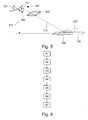
- Fig. 5 shows a perspective view of an aircraft 100 with an automatic landing system 101 according to an embodiment of the invention. There is also shown a runway 109, the ideal approach being shown by line 113.
- FIG. 3 is a flowchart for a method for determining position data of an aircraft for an automatic landing system of the aircraft according to an exemplary embodiment of the invention.
- the method comprises the step S1 of detecting first position data of the aircraft by a first position or distance measuring device and the step S2 of detecting second position data of the aircraft by a second position or distance measuring device.
- the step S3 of acquiring sensor data from which a direction in which a landmark is located and / or a distance of the landmark to the aircraft can be determined by a sensor device.
- the procedure further comprises the step S4 of generating a first hypothesis for the direction of the landmark based on the first position data and the step S5 of generating a second hypothesis for the direction of the landmark based on the second position data.
- step S6 of confirming or rejecting the first hypothesis and the second hypothesis by means of the sensor data acquired by the sensor device and step S7 deciding that only those position data for controlling the aircraft on which a confirmed hypothesis is based are to be used ,
Landscapes
- Engineering & Computer Science (AREA)
- Radar, Positioning & Navigation (AREA)
- Remote Sensing (AREA)
- Physics & Mathematics (AREA)
- General Physics & Mathematics (AREA)
- Computer Networks & Wireless Communication (AREA)
- Aviation & Aerospace Engineering (AREA)
- Automation & Control Theory (AREA)
- Electromagnetism (AREA)
- Traffic Control Systems (AREA)
- Radar Systems Or Details Thereof (AREA)
- Position Fixing By Use Of Radio Waves (AREA)
- Optical Radar Systems And Details Thereof (AREA)
Applications Claiming Priority (1)
| Application Number | Priority Date | Filing Date | Title |
|---|---|---|---|
| DE102014014446.1A DE102014014446A1 (de) | 2014-09-26 | 2014-09-26 | Redundantes Bestimmen von Positionsdaten für ein automatisches Landesystem |
Publications (2)
| Publication Number | Publication Date |
|---|---|
| EP3009794A1 true EP3009794A1 (fr) | 2016-04-20 |
| EP3009794B1 EP3009794B1 (fr) | 2017-04-12 |
Family
ID=54146893
Family Applications (1)
| Application Number | Title | Priority Date | Filing Date |
|---|---|---|---|
| EP15002625.0A Active EP3009794B1 (fr) | 2014-09-26 | 2015-09-08 | Determination redondante de donnees de position pour un systeme d'atterrissage automatique |
Country Status (6)
| Country | Link |
|---|---|
| US (1) | US9728094B2 (fr) |
| EP (1) | EP3009794B1 (fr) |
| CN (1) | CN105468006A (fr) |
| CA (1) | CA2905447A1 (fr) |
| DE (1) | DE102014014446A1 (fr) |
| RU (1) | RU2015138534A (fr) |
Families Citing this family (25)
| Publication number | Priority date | Publication date | Assignee | Title |
|---|---|---|---|---|
| US10001376B1 (en) * | 2015-02-19 | 2018-06-19 | Rockwell Collins, Inc. | Aircraft position monitoring system and method |
| FR3033924B1 (fr) * | 2015-03-16 | 2017-03-03 | Sagem Defense Securite | Procede d'assistance automatique a l'atterrissage d'un aeronef |
| FR3038991B1 (fr) * | 2015-07-16 | 2018-08-17 | Safran Electronics & Defense | Procede d'assistance automatique a l'atterrissage d'un aeronef |
| CN109643129A (zh) | 2016-08-26 | 2019-04-16 | 深圳市大疆创新科技有限公司 | 自主着陆的方法和系统 |
| FR3061343B1 (fr) * | 2016-12-22 | 2020-06-19 | Thales | Systeme d'aide a l'atterrissage d'un aeronef a voilure tournante sur une plateforme offshore |
| USD902078S1 (en) | 2017-06-07 | 2020-11-17 | MerchSource, LLC | Drone |
| USD851540S1 (en) | 2017-06-07 | 2019-06-18 | MerchSource, LLC | Drone |
| USD825380S1 (en) | 2017-06-27 | 2018-08-14 | MerchSource, LLC | Drone for kids |
| USD825669S1 (en) | 2017-07-10 | 2018-08-14 | MerchSource, LLC | Drone car |
| USD852091S1 (en) | 2017-07-20 | 2019-06-25 | MerchSource, LLC | Drone |
| USD862285S1 (en) | 2017-08-25 | 2019-10-08 | MerchSource, LLC | Drone |
| USD846445S1 (en) | 2017-09-15 | 2019-04-23 | MerchSource, LLC | Drone |
| US10402646B2 (en) | 2017-09-21 | 2019-09-03 | Amazon Technologies, Inc. | Object detection and avoidance for aerial vehicles |
| CN108319284B (zh) * | 2017-12-29 | 2022-01-14 | 北京航空航天大学 | 一种适用于障碍物环境的无人机下滑段轨迹设计方法 |
| US10616853B2 (en) * | 2017-12-29 | 2020-04-07 | Sonitor Technologies As | Location determination using acoustic-contextual data |
| CN109279014A (zh) * | 2018-03-15 | 2019-01-29 | 瞿美芬 | 一种用于打印的无人机系统 |
| DE102018120201A1 (de) * | 2018-08-20 | 2020-02-20 | Dr. Ing. H.C. F. Porsche Aktiengesellschaft | Landungsleitsystem für ein Luftfahrzeug und entsprechendes Luftfahrzeug |
| CN111422369B (zh) * | 2019-01-09 | 2023-09-19 | 复亚智能技术发展(江苏)有限公司 | 一种无人机自动机场及控制方法 |
| US12020583B2 (en) * | 2020-03-10 | 2024-06-25 | Honeywell International Inc. | Systems and methods providing assist-to-land and emergency land functions |
| CN111746816B (zh) * | 2020-05-18 | 2022-03-08 | 陈穗 | 一种飞机降落辅助装置及降落方法 |
| US11884417B2 (en) * | 2020-06-22 | 2024-01-30 | Rockwell Collins, Inc. | Emergency flight director |
| US11645928B2 (en) | 2020-09-28 | 2023-05-09 | Honeywell International Inc. | Method of using multiple approach guidance systems to provide higher integrity with improved performance and availability |
| CN112650304B (zh) * | 2021-01-20 | 2024-03-05 | 中国商用飞机有限责任公司北京民用飞机技术研究中心 | 无人机自主着陆系统、方法和无人机 |
| CN113759984B (zh) * | 2021-11-09 | 2022-02-08 | 山东天亚达新材料科技有限公司 | 一种竞速无人机的数据智能交互方法、装置及设备 |
| CN115061502B (zh) * | 2022-07-28 | 2025-05-02 | 浙江大学 | 无人机最优飞行高度确定方法、系统、电子设备及介质 |
Citations (2)
| Publication number | Priority date | Publication date | Assignee | Title |
|---|---|---|---|---|
| US6178363B1 (en) * | 1998-12-22 | 2001-01-23 | The Boeing Company | Inertially augmented GPS landing system |
| US20080077284A1 (en) * | 2006-04-19 | 2008-03-27 | Swope John M | System for position and velocity sense of an aircraft |
Family Cites Families (17)
| Publication number | Priority date | Publication date | Assignee | Title |
|---|---|---|---|---|
| US3059880A (en) * | 1960-06-10 | 1962-10-23 | North American Aviation Inc | Terminal predication aircraft landing system |
| DE4140406C2 (de) * | 1991-12-07 | 1998-09-03 | Daimler Benz Aerospace Ag | Verfahren zur Orientierung, Navigation, Führung und Überwachung von Flugzeugen |
| DE19521600A1 (de) * | 1995-06-14 | 1996-12-19 | Bodenseewerk Geraetetech | Landeverfahren für unbemannte Luftfahrzeuge |
| US6840480B2 (en) * | 2001-09-27 | 2005-01-11 | Ernest A. Carroll | Miniature, unmanned aircraft with interchangeable data module |
| JP4253239B2 (ja) * | 2003-10-07 | 2009-04-08 | 富士重工業株式会社 | 画像認識を用いた航法装置 |
| US7546183B1 (en) * | 2006-03-10 | 2009-06-09 | Frank Marcum | In-flight verification of instrument landing system signals |
| FR2902081B1 (fr) * | 2006-06-12 | 2008-07-11 | Airbus France Sas | Procede et dispositif d'assistance a l'atterissage pour aeronef |
| WO2009021068A1 (fr) * | 2007-08-06 | 2009-02-12 | Trx Systems, Inc. | Localiser, suivre et/ou surveiller le personnel et/ou les capitaux à la fois à l'intérieur et à l'extérieur |
| US8976340B2 (en) * | 2011-04-15 | 2015-03-10 | Advanced Scientific Concepts, Inc. | Ladar sensor for landing, docking and approach |
| JP5775354B2 (ja) * | 2011-04-28 | 2015-09-09 | 株式会社トプコン | 離着陸ターゲット装置及び自動離着陸システム |
| FR2978589B1 (fr) * | 2011-07-29 | 2013-08-23 | Airbus Operations Sas | Procede et dispositif de gestion optimisee de la trajectoire verticale d'un aeronef |
| FR2981778B1 (fr) * | 2011-10-24 | 2013-12-13 | Airbus Operations Sas | Procede et dispositif d'atterrissage automatique d'un aeronef sur une piste a forte pente. |
| FR2997066B1 (fr) * | 2012-10-22 | 2016-01-29 | Airbus Operations Sas | Procede d'aide au pilotage d'un aeronef lors d'un atterrissage et systeme d'aide au pilotage apte a mettre en œuvre ce procede |
| CN102980573A (zh) * | 2012-11-19 | 2013-03-20 | 中国航空工业集团公司第六三一研究所 | 通用飞机着陆径向线导航方法 |
| US9317040B1 (en) * | 2014-06-25 | 2016-04-19 | The United States Of America As Represented By The Secretary Of The Navy | Aircraft ground effect altimeter for autonomous landing control |
| US20160034607A1 (en) * | 2014-07-31 | 2016-02-04 | Aaron Maestas | Video-assisted landing guidance system and method |
| US20160259333A1 (en) * | 2015-02-27 | 2016-09-08 | Hoverfly Technologies, Inc. | Landing system for vertical take-off and landing aircraft |
-
2014
- 2014-09-26 DE DE102014014446.1A patent/DE102014014446A1/de not_active Withdrawn
-
2015
- 2015-09-08 EP EP15002625.0A patent/EP3009794B1/fr active Active
- 2015-09-10 RU RU2015138534A patent/RU2015138534A/ru not_active Application Discontinuation
- 2015-09-23 CA CA2905447A patent/CA2905447A1/fr active Pending
- 2015-09-25 CN CN201510619869.9A patent/CN105468006A/zh active Pending
- 2015-09-25 US US14/865,599 patent/US9728094B2/en active Active
Patent Citations (2)
| Publication number | Priority date | Publication date | Assignee | Title |
|---|---|---|---|---|
| US6178363B1 (en) * | 1998-12-22 | 2001-01-23 | The Boeing Company | Inertially augmented GPS landing system |
| US20080077284A1 (en) * | 2006-04-19 | 2008-03-27 | Swope John M | System for position and velocity sense of an aircraft |
Also Published As
| Publication number | Publication date |
|---|---|
| US9728094B2 (en) | 2017-08-08 |
| CN105468006A (zh) | 2016-04-06 |
| EP3009794B1 (fr) | 2017-04-12 |
| US20160104384A1 (en) | 2016-04-14 |
| DE102014014446A1 (de) | 2016-03-31 |
| RU2015138534A (ru) | 2017-03-20 |
| CA2905447A1 (fr) | 2016-03-26 |
Similar Documents
| Publication | Publication Date | Title |
|---|---|---|
| EP3009794B1 (fr) | Determination redondante de donnees de position pour un systeme d'atterrissage automatique | |
| EP3443301B1 (fr) | Procédé et système de détermination d'une position globale d'un premier repère | |
| DE102014112351B4 (de) | Sensorgestütztes fahrzeugpositionsbestimmungssystem | |
| DE102013015892B4 (de) | Positionsbestimmung eines Fahrzeugs auf oder über einer Planetenoberfläche | |
| DE102018114808A1 (de) | Verfahren zur automatischen Querführung eines Folgefahrzeugs in einem Fahrzeug-Platoon | |
| EP3538843B1 (fr) | Estimation d'une position propre | |
| DE102019133316A1 (de) | Bestimmen einer Position eines Fahrzeugs | |
| EP2381208B1 (fr) | Procédé de détermination de données de position d'un objet cible dans un système de référence | |
| EP3898368B1 (fr) | Procédé et système servant à déterminer une trajectoire corrigée d'un véhicule | |
| DE102020118629B4 (de) | Computerimplementiertes Verfahren zum Bestimmen der Validität einer geschätzten Position eines Fahrzeugs | |
| DE112022002120T5 (de) | Automatische Anpassung des vertikalen Profils eines Luftfahrzeugs auf der Grundlage einer Positionsunsicherheit | |
| WO2014146758A1 (fr) | Passerelle pour passagers | |
| DE102020118628A1 (de) | Verfahren und Vorrichtung zum Bestimmen einer Position eines Fahrzeugs | |
| EP3088845A1 (fr) | Determination d'un itineraire selectionne par un utilisateur d'un systeme de navigation | |
| DE10305993B4 (de) | Vermessungsverfahren zur Flug- und Fahrzeugführung | |
| DE102021107385A1 (de) | Verfahren zum Bestimmen, in welcher Fahrspur sich ein Fahrzeug befindet und System zum Betreiben einer Fahrerassistenzfunktion | |
| DE602004000072T2 (de) | Verfahren und Vorrichtung zur Bestimmung von mindestens einer Angabe bezüglich der vertikalen Position eines Luftfahrzeuges | |
| DE102022201199B3 (de) | Verfahren und Vorrichtung zur Überwachung eines Spurerkennungssystems, Spurerkennungssystem | |
| DE102020118622A1 (de) | Steuerung eines Fahrzeugs | |
| EP3640620A1 (fr) | Procédé de détection du passage d'une conduite souterraine au moyen d'un dispositif de détection aérien | |
| DE102018204851A1 (de) | Verfahren zur Plausibilisierung einer satellitengestützt ermittelten Fahrzeugposition | |
| EP3407324A1 (fr) | Procédé de surveillance d'un véhicule au moyen d'au moins un véhicule aérien sans pilote, appareil de commande et véhicule aérien sans pilote | |
| DE102018200218A1 (de) | Positionsbestimmung mittels Beobachtungseinrichtung | |
| DE102023133433A1 (de) | Autonom fahrendes fahrzeug und verfahren zum fahren desselben | |
| DE102023204912A1 (de) | Dynamische Validierung einer Funktion einer Sensoreinheit eines Schienenfahrzeugs zur Objektlokalisierung |
Legal Events
| Date | Code | Title | Description |
|---|---|---|---|
| PUAI | Public reference made under article 153(3) epc to a published international application that has entered the european phase |
Free format text: ORIGINAL CODE: 0009012 |
|
| AK | Designated contracting states |
Kind code of ref document: A1 Designated state(s): AL AT BE BG CH CY CZ DE DK EE ES FI FR GB GR HR HU IE IS IT LI LT LU LV MC MK MT NL NO PL PT RO RS SE SI SK SM TR |
|
| AX | Request for extension of the european patent |
Extension state: BA ME |
|
| REG | Reference to a national code |
Ref country code: DE Ref legal event code: R079 Ref document number: 502015000828 Country of ref document: DE Free format text: PREVIOUS MAIN CLASS: G01C0021000000 Ipc: G01S0019130000 |
|
| 17P | Request for examination filed |
Effective date: 20160921 |
|
| RBV | Designated contracting states (corrected) |
Designated state(s): AL AT BE BG CH CY CZ DE DK EE ES FI FR GB GR HR HU IE IS IT LI LT LU LV MC MK MT NL NO PL PT RO RS SE SI SK SM TR |
|
| RIC1 | Information provided on ipc code assigned before grant |
Ipc: G01S 19/13 20100101AFI20161028BHEP Ipc: G08G 5/02 20060101ALI20161028BHEP Ipc: G05D 1/06 20060101ALI20161028BHEP Ipc: G01S 13/02 20060101ALI20161028BHEP Ipc: G01C 21/00 20060101ALI20161028BHEP |
|
| GRAP | Despatch of communication of intention to grant a patent |
Free format text: ORIGINAL CODE: EPIDOSNIGR1 |
|
| INTG | Intention to grant announced |
Effective date: 20161222 |
|
| GRAS | Grant fee paid |
Free format text: ORIGINAL CODE: EPIDOSNIGR3 |
|
| GRAA | (expected) grant |
Free format text: ORIGINAL CODE: 0009210 |
|
| AK | Designated contracting states |
Kind code of ref document: B1 Designated state(s): AL AT BE BG CH CY CZ DE DK EE ES FI FR GB GR HR HU IE IS IT LI LT LU LV MC MK MT NL NO PL PT RO RS SE SI SK SM TR |
|
| REG | Reference to a national code |
Ref country code: GB Ref legal event code: FG4D Free format text: NOT ENGLISH |
|
| REG | Reference to a national code |
Ref country code: CH Ref legal event code: EP |
|
| REG | Reference to a national code |
Ref country code: IE Ref legal event code: FG4D Free format text: LANGUAGE OF EP DOCUMENT: GERMAN |
|
| REG | Reference to a national code |
Ref country code: AT Ref legal event code: REF Ref document number: 884445 Country of ref document: AT Kind code of ref document: T Effective date: 20170515 |
|
| REG | Reference to a national code |
Ref country code: DE Ref legal event code: R096 Ref document number: 502015000828 Country of ref document: DE |
|
| REG | Reference to a national code |
Ref country code: SE Ref legal event code: TRGR |
|
| REG | Reference to a national code |
Ref country code: NL Ref legal event code: MP Effective date: 20170412 |
|
| REG | Reference to a national code |
Ref country code: LT Ref legal event code: MG4D |
|
| REG | Reference to a national code |
Ref country code: FR Ref legal event code: PLFP Year of fee payment: 3 |
|
| PG25 | Lapsed in a contracting state [announced via postgrant information from national office to epo] |
Ref country code: NL Free format text: LAPSE BECAUSE OF FAILURE TO SUBMIT A TRANSLATION OF THE DESCRIPTION OR TO PAY THE FEE WITHIN THE PRESCRIBED TIME-LIMIT Effective date: 20170412 |
|
| PG25 | Lapsed in a contracting state [announced via postgrant information from national office to epo] |
Ref country code: ES Free format text: LAPSE BECAUSE OF FAILURE TO SUBMIT A TRANSLATION OF THE DESCRIPTION OR TO PAY THE FEE WITHIN THE PRESCRIBED TIME-LIMIT Effective date: 20170412 Ref country code: GR Free format text: LAPSE BECAUSE OF FAILURE TO SUBMIT A TRANSLATION OF THE DESCRIPTION OR TO PAY THE FEE WITHIN THE PRESCRIBED TIME-LIMIT Effective date: 20170713 Ref country code: FI Free format text: LAPSE BECAUSE OF FAILURE TO SUBMIT A TRANSLATION OF THE DESCRIPTION OR TO PAY THE FEE WITHIN THE PRESCRIBED TIME-LIMIT Effective date: 20170412 Ref country code: LT Free format text: LAPSE BECAUSE OF FAILURE TO SUBMIT A TRANSLATION OF THE DESCRIPTION OR TO PAY THE FEE WITHIN THE PRESCRIBED TIME-LIMIT Effective date: 20170412 Ref country code: NO Free format text: LAPSE BECAUSE OF FAILURE TO SUBMIT A TRANSLATION OF THE DESCRIPTION OR TO PAY THE FEE WITHIN THE PRESCRIBED TIME-LIMIT Effective date: 20170712 Ref country code: HR Free format text: LAPSE BECAUSE OF FAILURE TO SUBMIT A TRANSLATION OF THE DESCRIPTION OR TO PAY THE FEE WITHIN THE PRESCRIBED TIME-LIMIT Effective date: 20170412 |
|
| PG25 | Lapsed in a contracting state [announced via postgrant information from national office to epo] |
Ref country code: RS Free format text: LAPSE BECAUSE OF FAILURE TO SUBMIT A TRANSLATION OF THE DESCRIPTION OR TO PAY THE FEE WITHIN THE PRESCRIBED TIME-LIMIT Effective date: 20170412 Ref country code: PL Free format text: LAPSE BECAUSE OF FAILURE TO SUBMIT A TRANSLATION OF THE DESCRIPTION OR TO PAY THE FEE WITHIN THE PRESCRIBED TIME-LIMIT Effective date: 20170412 Ref country code: BG Free format text: LAPSE BECAUSE OF FAILURE TO SUBMIT A TRANSLATION OF THE DESCRIPTION OR TO PAY THE FEE WITHIN THE PRESCRIBED TIME-LIMIT Effective date: 20170712 Ref country code: LV Free format text: LAPSE BECAUSE OF FAILURE TO SUBMIT A TRANSLATION OF THE DESCRIPTION OR TO PAY THE FEE WITHIN THE PRESCRIBED TIME-LIMIT Effective date: 20170412 Ref country code: IS Free format text: LAPSE BECAUSE OF FAILURE TO SUBMIT A TRANSLATION OF THE DESCRIPTION OR TO PAY THE FEE WITHIN THE PRESCRIBED TIME-LIMIT Effective date: 20170812 |
|
| REG | Reference to a national code |
Ref country code: DE Ref legal event code: R097 Ref document number: 502015000828 Country of ref document: DE |
|
| PG25 | Lapsed in a contracting state [announced via postgrant information from national office to epo] |
Ref country code: RO Free format text: LAPSE BECAUSE OF FAILURE TO SUBMIT A TRANSLATION OF THE DESCRIPTION OR TO PAY THE FEE WITHIN THE PRESCRIBED TIME-LIMIT Effective date: 20170412 Ref country code: DK Free format text: LAPSE BECAUSE OF FAILURE TO SUBMIT A TRANSLATION OF THE DESCRIPTION OR TO PAY THE FEE WITHIN THE PRESCRIBED TIME-LIMIT Effective date: 20170412 Ref country code: SK Free format text: LAPSE BECAUSE OF FAILURE TO SUBMIT A TRANSLATION OF THE DESCRIPTION OR TO PAY THE FEE WITHIN THE PRESCRIBED TIME-LIMIT Effective date: 20170412 Ref country code: CZ Free format text: LAPSE BECAUSE OF FAILURE TO SUBMIT A TRANSLATION OF THE DESCRIPTION OR TO PAY THE FEE WITHIN THE PRESCRIBED TIME-LIMIT Effective date: 20170412 Ref country code: EE Free format text: LAPSE BECAUSE OF FAILURE TO SUBMIT A TRANSLATION OF THE DESCRIPTION OR TO PAY THE FEE WITHIN THE PRESCRIBED TIME-LIMIT Effective date: 20170412 |
|
| PLBE | No opposition filed within time limit |
Free format text: ORIGINAL CODE: 0009261 |
|
| STAA | Information on the status of an ep patent application or granted ep patent |
Free format text: STATUS: NO OPPOSITION FILED WITHIN TIME LIMIT |
|
| PG25 | Lapsed in a contracting state [announced via postgrant information from national office to epo] |
Ref country code: IT Free format text: LAPSE BECAUSE OF FAILURE TO SUBMIT A TRANSLATION OF THE DESCRIPTION OR TO PAY THE FEE WITHIN THE PRESCRIBED TIME-LIMIT Effective date: 20170412 Ref country code: SM Free format text: LAPSE BECAUSE OF FAILURE TO SUBMIT A TRANSLATION OF THE DESCRIPTION OR TO PAY THE FEE WITHIN THE PRESCRIBED TIME-LIMIT Effective date: 20170412 |
|
| 26N | No opposition filed |
Effective date: 20180115 |
|
| PG25 | Lapsed in a contracting state [announced via postgrant information from national office to epo] |
Ref country code: MC Free format text: LAPSE BECAUSE OF FAILURE TO SUBMIT A TRANSLATION OF THE DESCRIPTION OR TO PAY THE FEE WITHIN THE PRESCRIBED TIME-LIMIT Effective date: 20170412 Ref country code: SI Free format text: LAPSE BECAUSE OF FAILURE TO SUBMIT A TRANSLATION OF THE DESCRIPTION OR TO PAY THE FEE WITHIN THE PRESCRIBED TIME-LIMIT Effective date: 20170412 |
|
| REG | Reference to a national code |
Ref country code: IE Ref legal event code: MM4A |
|
| REG | Reference to a national code |
Ref country code: BE Ref legal event code: MM Effective date: 20170930 |
|
| PG25 | Lapsed in a contracting state [announced via postgrant information from national office to epo] |
Ref country code: LU Free format text: LAPSE BECAUSE OF NON-PAYMENT OF DUE FEES Effective date: 20170908 |
|
| PG25 | Lapsed in a contracting state [announced via postgrant information from national office to epo] |
Ref country code: IE Free format text: LAPSE BECAUSE OF NON-PAYMENT OF DUE FEES Effective date: 20170908 |
|
| PG25 | Lapsed in a contracting state [announced via postgrant information from national office to epo] |
Ref country code: BE Free format text: LAPSE BECAUSE OF NON-PAYMENT OF DUE FEES Effective date: 20170930 |
|
| REG | Reference to a national code |
Ref country code: FR Ref legal event code: PLFP Year of fee payment: 4 |
|
| PG25 | Lapsed in a contracting state [announced via postgrant information from national office to epo] |
Ref country code: MT Free format text: LAPSE BECAUSE OF FAILURE TO SUBMIT A TRANSLATION OF THE DESCRIPTION OR TO PAY THE FEE WITHIN THE PRESCRIBED TIME-LIMIT Effective date: 20170412 |
|
| REG | Reference to a national code |
Ref country code: CH Ref legal event code: PL |
|
| PG25 | Lapsed in a contracting state [announced via postgrant information from national office to epo] |
Ref country code: HU Free format text: LAPSE BECAUSE OF FAILURE TO SUBMIT A TRANSLATION OF THE DESCRIPTION OR TO PAY THE FEE WITHIN THE PRESCRIBED TIME-LIMIT; INVALID AB INITIO Effective date: 20150908 |
|
| PG25 | Lapsed in a contracting state [announced via postgrant information from national office to epo] |
Ref country code: LI Free format text: LAPSE BECAUSE OF NON-PAYMENT OF DUE FEES Effective date: 20180930 Ref country code: CH Free format text: LAPSE BECAUSE OF NON-PAYMENT OF DUE FEES Effective date: 20180930 |
|
| PG25 | Lapsed in a contracting state [announced via postgrant information from national office to epo] |
Ref country code: CY Free format text: LAPSE BECAUSE OF FAILURE TO SUBMIT A TRANSLATION OF THE DESCRIPTION OR TO PAY THE FEE WITHIN THE PRESCRIBED TIME-LIMIT Effective date: 20170412 |
|
| PG25 | Lapsed in a contracting state [announced via postgrant information from national office to epo] |
Ref country code: MK Free format text: LAPSE BECAUSE OF FAILURE TO SUBMIT A TRANSLATION OF THE DESCRIPTION OR TO PAY THE FEE WITHIN THE PRESCRIBED TIME-LIMIT Effective date: 20170412 |
|
| PG25 | Lapsed in a contracting state [announced via postgrant information from national office to epo] |
Ref country code: TR Free format text: LAPSE BECAUSE OF FAILURE TO SUBMIT A TRANSLATION OF THE DESCRIPTION OR TO PAY THE FEE WITHIN THE PRESCRIBED TIME-LIMIT Effective date: 20170412 |
|
| PG25 | Lapsed in a contracting state [announced via postgrant information from national office to epo] |
Ref country code: PT Free format text: LAPSE BECAUSE OF FAILURE TO SUBMIT A TRANSLATION OF THE DESCRIPTION OR TO PAY THE FEE WITHIN THE PRESCRIBED TIME-LIMIT Effective date: 20170412 |
|
| PG25 | Lapsed in a contracting state [announced via postgrant information from national office to epo] |
Ref country code: AL Free format text: LAPSE BECAUSE OF FAILURE TO SUBMIT A TRANSLATION OF THE DESCRIPTION OR TO PAY THE FEE WITHIN THE PRESCRIBED TIME-LIMIT Effective date: 20170412 |
|
| REG | Reference to a national code |
Ref country code: AT Ref legal event code: MM01 Ref document number: 884445 Country of ref document: AT Kind code of ref document: T Effective date: 20200908 |
|
| PG25 | Lapsed in a contracting state [announced via postgrant information from national office to epo] |
Ref country code: AT Free format text: LAPSE BECAUSE OF NON-PAYMENT OF DUE FEES Effective date: 20200908 |
|
| PGFP | Annual fee paid to national office [announced via postgrant information from national office to epo] |
Ref country code: DE Payment date: 20250919 Year of fee payment: 11 |
|
| PGFP | Annual fee paid to national office [announced via postgrant information from national office to epo] |
Ref country code: GB Payment date: 20250919 Year of fee payment: 11 |
|
| PGFP | Annual fee paid to national office [announced via postgrant information from national office to epo] |
Ref country code: FR Payment date: 20250922 Year of fee payment: 11 |
|
| PGFP | Annual fee paid to national office [announced via postgrant information from national office to epo] |
Ref country code: SE Payment date: 20250918 Year of fee payment: 11 |