EP3010124A2 - Verfahren zur herstellung einer stromschiene - Google Patents
Verfahren zur herstellung einer stromschiene Download PDFInfo
- Publication number
- EP3010124A2 EP3010124A2 EP15186389.1A EP15186389A EP3010124A2 EP 3010124 A2 EP3010124 A2 EP 3010124A2 EP 15186389 A EP15186389 A EP 15186389A EP 3010124 A2 EP3010124 A2 EP 3010124A2
- Authority
- EP
- European Patent Office
- Prior art keywords
- conductor
- putty
- conductor bar
- tape
- bar
- Prior art date
- Legal status (The legal status is an assumption and is not a legal conclusion. Google has not performed a legal analysis and makes no representation as to the accuracy of the status listed.)
- Granted
Links
Images


Classifications
-
- H—ELECTRICITY
- H02—GENERATION; CONVERSION OR DISTRIBUTION OF ELECTRIC POWER
- H02K—DYNAMO-ELECTRIC MACHINES
- H02K15/00—Processes or apparatus specially adapted for manufacturing, assembling, maintaining or repairing of dynamo-electric machines
- H02K15/04—Processes or apparatus specially adapted for manufacturing, assembling, maintaining or repairing of dynamo-electric machines of windings prior to their mounting into the machines
- H02K15/0414—Processes or apparatus specially adapted for manufacturing, assembling, maintaining or repairing of dynamo-electric machines of windings prior to their mounting into the machines the windings consisting of separate elements, e.g. bars, segments or half coils
-
- B—PERFORMING OPERATIONS; TRANSPORTING
- B29—WORKING OF PLASTICS; WORKING OF SUBSTANCES IN A PLASTIC STATE IN GENERAL
- B29C—SHAPING OR JOINING OF PLASTICS; SHAPING OF MATERIAL IN A PLASTIC STATE, NOT OTHERWISE PROVIDED FOR; AFTER-TREATMENT OF THE SHAPED PRODUCTS, e.g. REPAIRING
- B29C43/00—Compression moulding, i.e. applying external pressure to flow the moulding material; Apparatus therefor
- B29C43/003—Compression moulding, i.e. applying external pressure to flow the moulding material; Apparatus therefor characterised by the choice of material
-
- B—PERFORMING OPERATIONS; TRANSPORTING
- B29—WORKING OF PLASTICS; WORKING OF SUBSTANCES IN A PLASTIC STATE IN GENERAL
- B29C—SHAPING OR JOINING OF PLASTICS; SHAPING OF MATERIAL IN A PLASTIC STATE, NOT OTHERWISE PROVIDED FOR; AFTER-TREATMENT OF THE SHAPED PRODUCTS, e.g. REPAIRING
- B29C43/00—Compression moulding, i.e. applying external pressure to flow the moulding material; Apparatus therefor
- B29C43/02—Compression moulding, i.e. applying external pressure to flow the moulding material; Apparatus therefor of articles of definite length, i.e. discrete articles
- B29C43/18—Compression moulding, i.e. applying external pressure to flow the moulding material; Apparatus therefor of articles of definite length, i.e. discrete articles incorporating preformed parts or layers, e.g. compression moulding around inserts or for coating articles
-
- B—PERFORMING OPERATIONS; TRANSPORTING
- B29—WORKING OF PLASTICS; WORKING OF SUBSTANCES IN A PLASTIC STATE IN GENERAL
- B29C—SHAPING OR JOINING OF PLASTICS; SHAPING OF MATERIAL IN A PLASTIC STATE, NOT OTHERWISE PROVIDED FOR; AFTER-TREATMENT OF THE SHAPED PRODUCTS, e.g. REPAIRING
- B29C43/00—Compression moulding, i.e. applying external pressure to flow the moulding material; Apparatus therefor
- B29C43/32—Component parts, details or accessories; Auxiliary operations
- B29C43/36—Moulds for making articles of definite length, i.e. discrete articles
-
- H—ELECTRICITY
- H01—ELECTRIC ELEMENTS
- H01B—CABLES; CONDUCTORS; INSULATORS; SELECTION OF MATERIALS FOR THEIR CONDUCTIVE, INSULATING OR DIELECTRIC PROPERTIES
- H01B13/00—Apparatus or processes specially adapted for manufacturing conductors or cables
- H01B13/06—Insulating conductors or cables
-
- H—ELECTRICITY
- H02—GENERATION; CONVERSION OR DISTRIBUTION OF ELECTRIC POWER
- H02K—DYNAMO-ELECTRIC MACHINES
- H02K15/00—Processes or apparatus specially adapted for manufacturing, assembling, maintaining or repairing of dynamo-electric machines
- H02K15/10—Applying solid insulation to windings, stators or rotors, e.g. applying insulating tapes
- H02K15/105—Applying solid insulation to windings, stators or rotors, e.g. applying insulating tapes to the windings
-
- H—ELECTRICITY
- H02—GENERATION; CONVERSION OR DISTRIBUTION OF ELECTRIC POWER
- H02K—DYNAMO-ELECTRIC MACHINES
- H02K15/00—Processes or apparatus specially adapted for manufacturing, assembling, maintaining or repairing of dynamo-electric machines
- H02K15/12—Impregnating, moulding insulation, heating or drying of windings, stators, rotors or machines
-
- B—PERFORMING OPERATIONS; TRANSPORTING
- B29—WORKING OF PLASTICS; WORKING OF SUBSTANCES IN A PLASTIC STATE IN GENERAL
- B29C—SHAPING OR JOINING OF PLASTICS; SHAPING OF MATERIAL IN A PLASTIC STATE, NOT OTHERWISE PROVIDED FOR; AFTER-TREATMENT OF THE SHAPED PRODUCTS, e.g. REPAIRING
- B29C43/00—Compression moulding, i.e. applying external pressure to flow the moulding material; Apparatus therefor
- B29C43/02—Compression moulding, i.e. applying external pressure to flow the moulding material; Apparatus therefor of articles of definite length, i.e. discrete articles
- B29C43/18—Compression moulding, i.e. applying external pressure to flow the moulding material; Apparatus therefor of articles of definite length, i.e. discrete articles incorporating preformed parts or layers, e.g. compression moulding around inserts or for coating articles
- B29C2043/185—Compression moulding, i.e. applying external pressure to flow the moulding material; Apparatus therefor of articles of definite length, i.e. discrete articles incorporating preformed parts or layers, e.g. compression moulding around inserts or for coating articles using adhesives
-
- B—PERFORMING OPERATIONS; TRANSPORTING
- B29—WORKING OF PLASTICS; WORKING OF SUBSTANCES IN A PLASTIC STATE IN GENERAL
- B29K—INDEXING SCHEME ASSOCIATED WITH SUBCLASSES B29B, B29C OR B29D, RELATING TO MOULDING MATERIALS OR TO MATERIALS FOR MOULDS, REINFORCEMENTS, FILLERS OR PREFORMED PARTS, e.g. INSERTS
- B29K2063/00—Use of EP, i.e. epoxy resins or derivatives thereof, as moulding material
-
- B—PERFORMING OPERATIONS; TRANSPORTING
- B29—WORKING OF PLASTICS; WORKING OF SUBSTANCES IN A PLASTIC STATE IN GENERAL
- B29K—INDEXING SCHEME ASSOCIATED WITH SUBCLASSES B29B, B29C OR B29D, RELATING TO MOULDING MATERIALS OR TO MATERIALS FOR MOULDS, REINFORCEMENTS, FILLERS OR PREFORMED PARTS, e.g. INSERTS
- B29K2105/00—Condition, form or state of moulded material or of the material to be shaped
- B29K2105/06—Condition, form or state of moulded material or of the material to be shaped containing reinforcements, fillers or inserts
- B29K2105/20—Inserts
-
- B—PERFORMING OPERATIONS; TRANSPORTING
- B29—WORKING OF PLASTICS; WORKING OF SUBSTANCES IN A PLASTIC STATE IN GENERAL
- B29K—INDEXING SCHEME ASSOCIATED WITH SUBCLASSES B29B, B29C OR B29D, RELATING TO MOULDING MATERIALS OR TO MATERIALS FOR MOULDS, REINFORCEMENTS, FILLERS OR PREFORMED PARTS, e.g. INSERTS
- B29K2309/00—Use of inorganic materials not provided for in groups B29K2303/00 - B29K2307/00, as reinforcement
- B29K2309/10—Mica
-
- B—PERFORMING OPERATIONS; TRANSPORTING
- B29—WORKING OF PLASTICS; WORKING OF SUBSTANCES IN A PLASTIC STATE IN GENERAL
- B29K—INDEXING SCHEME ASSOCIATED WITH SUBCLASSES B29B, B29C OR B29D, RELATING TO MOULDING MATERIALS OR TO MATERIALS FOR MOULDS, REINFORCEMENTS, FILLERS OR PREFORMED PARTS, e.g. INSERTS
- B29K2995/00—Properties of moulding materials, reinforcements, fillers, preformed parts or moulds
- B29K2995/0003—Properties of moulding materials, reinforcements, fillers, preformed parts or moulds having particular electrical or magnetic properties, e.g. piezoelectric
- B29K2995/0005—Conductive
-
- B—PERFORMING OPERATIONS; TRANSPORTING
- B29—WORKING OF PLASTICS; WORKING OF SUBSTANCES IN A PLASTIC STATE IN GENERAL
- B29L—INDEXING SCHEME ASSOCIATED WITH SUBCLASS B29C, RELATING TO PARTICULAR ARTICLES
- B29L2031/00—Other particular articles
- B29L2031/34—Electrical apparatus, e.g. sparking plugs or parts thereof
- B29L2031/3406—Components, e.g. resistors
-
- B—PERFORMING OPERATIONS; TRANSPORTING
- B29—WORKING OF PLASTICS; WORKING OF SUBSTANCES IN A PLASTIC STATE IN GENERAL
- B29L—INDEXING SCHEME ASSOCIATED WITH SUBCLASS B29C, RELATING TO PARTICULAR ARTICLES
- B29L2031/00—Other particular articles
- B29L2031/748—Machines or parts thereof not otherwise provided for
- B29L2031/749—Motors
-
- H—ELECTRICITY
- H02—GENERATION; CONVERSION OR DISTRIBUTION OF ELECTRIC POWER
- H02K—DYNAMO-ELECTRIC MACHINES
- H02K3/00—Details of windings
- H02K3/04—Windings characterised by the conductor shape, form or construction, e.g. with bar conductors
- H02K3/12—Windings characterised by the conductor shape, form or construction, e.g. with bar conductors arranged in slots
- H02K3/14—Windings characterised by the conductor shape, form or construction, e.g. with bar conductors arranged in slots with transposed conductors, e.g. twisted conductors
-
- H—ELECTRICITY
- H02—GENERATION; CONVERSION OR DISTRIBUTION OF ELECTRIC POWER
- H02K—DYNAMO-ELECTRIC MACHINES
- H02K3/00—Details of windings
- H02K3/32—Windings characterised by the shape, form or construction of the insulation
- H02K3/40—Windings characterised by the shape, form or construction of the insulation for high voltage, e.g. affording protection against corona discharges
Definitions
- the present disclosure relates to a method for fabrication of a conductor bar and to a use of a conductor tape with applied putty for fabrication of a conductor bar.
- the winding conductors of dynamoelectric machines are placed in slots in a laminated magnetic core.
- magnetic fluxes occur across the slots which cause induced voltages and eddy currents in the conductor.
- Similar fluxes link the end turn portions of the conductor outside the slot, with some additional leakage flux from the rotor and stator, and cause similar induced voltages in the end portions.
- the conductors of large machines are always of stranded construction, being built up of a substantial number of relatively thin strands to minimize the eddy current loss.
- Conductor bars have a length of several metres depending on the electric machine to be applied.
- the mechanical impact of the transposition of the strands is that the surface structure of the small or narrow side of the conductor bar becomes uneven.
- This uneven surface of the conductor bar in this fabrication step complicates the wrapping of the main insulation layer and ends up in undefined electrical field strengths.
- a putty is applied to the surface of the conductor bar before wrapping the main insulation around the conductor bar.
- rectangular rods from steel are aligned along the conductor bar with putty.
- a disadvantage of this fabrication method is that the conductor bar is sharp-edged in the area at which the putty is applied.
- the polishing step is commonly done manually and does not always result in an even and sufficient quality for an increased high electrical field strength design. Undefined radii and edges enhance the electric field strength undesirably leading to a reduced life time of the respective conductor bar.
- these show different views of a conductor bar 2, a conductor tape 3 with putty 4 and release foil 6, and a pressing mould 10 for fabricating a conductor bar 2, wherein like reference numerals designate identical or corresponding parts throughout the several views.
- Fig. 1 shows a schematic perspective view of a part of a conductor bar 2 for application in an electric machine, especially as a bar to introduce into notches in a stator or a rotor of a dynamo electrical machine.
- the conductor bar 2 is cut for sake of illustration.
- the conductor bar 2 comprises two abut layers of stacked strands 23 next to each other.
- the strands 23 are commonly made from copper and have a rectangular cross-section with defined radii and a single strand insulation.
- the conductor bar 2 has an elongated nearly rectangular cross-section with a long height and a small or narrow breadth.
- the strands 23 in the foreground stack have an orientation upwards and the strands 23 in the background stack have an orientation downwards, regarded from the right to the left.
- the strand 23 moves from the bottom to the top of the stack at which the strand 23 changes the position to the stack in the background and in turn moves down to the bottom of the stack of strands 23 again.
- a putty 4 is applied to the two narrow sides 22 on top and at the bottom of the conductor bar 2, as illustrated in Fig. 1 in a schematic way.
- the putty 4 according to this disclosure can be an electrically conducting putty 4, alternatively the putty can be an electrically non-conducting putty 4, or a semi-conductive material.
- the putty 4 is a viscous epoxy resin filled with mica powder and conductive additives and has a resistivity between 1k ⁇ *cm 2 /cm and 50k ⁇ * cm 2 /cm. Further examples of materials of the putty 4 are silicon or thermoplastics. The putty 4 gets cured and hardened later. As is visible in Fig.
- the putty 4 is not applied at the longitudinal or long side of the conductor bar 2. However, during fabrication a flow of putty along the longitudinal side can occur.
- the conductor tape 3, which is a conductive tape or a mica tape/ paper, is applied at the putty 4 and fully covers the putty 4 at the top and at the bottom of the conductor bar 2.
- the conductor tape 3 is a strip of rectangular shaped material, as can be seen in Fig. 1 .
- the conductor tape 3 comprises next to the mica tape or mica paper a support structure. This support structure can comprise fibre fabric, e.g. E-glass, foils, e.g. PET, or a fleece.
- the conductor tape 3 can be designed according to the well-known state of the art.
- the conductor tape 3 in this finished fabrication step covers the hardened putty 4 and also a part of the long sides, here around three strands 23 at the long sides are covered by the conductor tape 3.
- the whole conductor bar 2 is covered with a layer of a main insulation 25, which is shown in Fig. 1 in a cut view at the right side.
- Fig. 2 shows a schematic part of the conductor tape 3, in an example made from mica.
- the putty 4 is applied onto the conductor tape 3.
- This is the perspective at the side of the conductor bar 2 to which the conductor tape 3 with putty 4 is attached.
- the breadth of the strip of putty 4 essentially in the middle of the conductor tape 3 is smaller than the breadth of the conductor tape 3, with other words the conductor tape 3 is broader than the putty 4.
- the breadth of the strip of putty 4 is essentially identical to the breadth of the conductor bar 2, i.e. the narrow side 22 of the conductor bar 2.
- the breadth here is commonly the horizontal dimension in the plane of Fig. 2 .
- the conductor tape 3 has a bigger breadth than the narrow side 22 of the conductor bar 2 and overlaps over the edges of the narrow side 22 when applied to the conductor bar 2, as visible in Fig. 1 .
- the putty 4 is not hardened when applied to the conductor tape 3, thus the putty 4 sticks to the conductor tape 4 without further fasteners.
- On the conductor tape 3 and the putty 4 a release foil 6 is attached.
- the release foil 6 fully covers the putty 4, whereas the release foil 6 can have a smaller breadth than the conductor tape 3.
- the release foil 6 is releasably stuck to the putty 4 without further fasteners.
- Shown in Fig. 2 is a transparent section 61 for sake of illustrating the structure of the three layers, conductor tape 3, putty 4, and release foil 6, shown with dashed lines.
- the release foil 6 is naturally not transparent necessarily.
- Fig. 3 shows a schematic front view of a cross-section of a pressing mould 10.
- the pressing mould 10 consists of four parts, an upper part 15, two middle parts 14, and a bottom part 13.
- the pressing mould 10 is designed to enclose a conductor bar 2 as described above when the four parts are assembled as shown in Fig. 3 .
- the pressing mould 10 has a length of several metres to house main parts of the conductor bar 2 during the manufacturing steps of the conductor bar 2.
- the parts 12-17 are assembled by means of a crane or manually.
- the outer faces of the pressing mould 10 usually have a rectangular shape similar to the cross-section of the conductor bar 2 to be encompassed.
- the inner faces of the pressing mould 10 are straight along the height, the longer side, to abut against the conductor bar 2 during manufacturing.
- the inner faces of the smaller side of the pressing mould 10 are rounded, the faces have rounded edges 12 with a defined radius there.
- the inner faces of the pressing mould 10 to abut the conductor bar 2 have a cross-section of a geometry of a kind of super ellipse, also called Lame oval, with mainly straight lines at the bottom, top, and sides of the cross-section like a rectangular, and bended lines to connect the straight lines.
- the geometry of the cross-section of the inner faces is thus a modified rectangle with no 90° angle in the contrary to a rectangle. This can be seen in Fig. 3 .
- the rounded edges 12 abut the conductor tape 3 during fabrication of the conductor bar 2.
- the conductor tape 3 can be a tape made from mica or an electrically conducting tape.
- the effect of the rounded edges 12 of the pressing mould 10 and the conductor tape 3 overlapping over the putty 4 is that the putty 4 on the conductor tape 3 is fixed to the rude conductor bar 2 in a defined manner without sharp edges at the hardened putty 4. After hardening the putty 4 and removing the pressing mould 10 from the conductor bar 2 there is no need for a further fabrication step to milling and cleaning the putty 4.
- the edges of the finished conductor bar 2 have defined radii which is especially advantageous to avoid locally enhanced electrical field strength at the edges in operation.
- the putty 4 By the use of the specific pressing mould 10 and the conductor tape 3 in the described manner the putty 4 is applied on the spot, the putty 4 with the conductor tape 3 below can be fixed to the conductor bar 2 accurately at defined points so the end faces of the putty 4 are precisely defined.
- the fabrication process has the following steps.
- the raw conductor bar 2 as shown at the left of Fig. 1 is commonly impregnated and the strands 23 are arranged in a transposed manner as shown and described.
- the not hardened putty 4 with some viscosity and adhesion power is applied to the conductor tape 3 which can be a tape from mica or mica compositions in an example.
- the conductor tape 3 has a bigger breadth than the breadth of the putty 4 along the conductor tape 3, this means at the left and at the right of the conductor tape 3 there are free spaces not coated with the putty 4.
- the conductor tape 3 has a breadth of approximately 15-30mm broader than the narrow side 22 of the conductor bar 2.
- the conductor tape 3 with putty 4 and release foil 6 can be rolled up to a roll for transport reasons. In the method step of applying the putty 4 to the conductor bar 2 the conductor tape 3 is then unrolled.
- This step can be done automatically in a winder machine.
- the conductor tape 3 is applied to the two narrow sides 22 of the conductor bar 2 with the putty 4 directed to the conductor bar 2 and the conductor tape 3 more distant from the conductor bar 2 not contacting the conductor bar 2 at the spots at which the putty 4 is applied.
- the part of the conductor tape 3 not coated with putty 4 is applied directly to the conductor bar 2. This is the part at the long side or longitudinal side of the conductor bar 2.
- the configuration is such that the putty 4 captures the narrow sides 22 of the conductor bar 2 and the conductor tape 3 covers the putty 4 at the narrow sides 22 and captures a small part of the larger side of the conductor bar 2, as can be seen in Fig. 1 .
- the application of the putty 4 with the conductor tape 3 can be done manually or by means of a machine, a winder.
- the winder is a machine known in the state of the art comprising rollers to transport the conductor band 3 and supports for the conductor bar 2.
- An additional foil 8 is wrapped around the whole conductor bar 2 and envelopes the whole conductor bar 2. The additional foil 8 ensures that the pressing mould 10 is not contaminated with putty 4 and wear at the pressing mould 10 is avoided. This is illustrated schematically in Fig.
- the next fabrication step as an example of the invention is to mount the four parts 13, 14, 15 of the pressing mould 10 around the conductor bar 2.
- the pressing mould 10 is configured according to Fig. 3 , here without the conductor bar 2.
- the conductor bar 2 is then fixed within the pressing mould 10.
- the conductor tape 3 adjacent to the bare conductor bar 2 abuts the narrow faces at the bottom and at the top, the rounded edges 12, and a small part of the larger sides of the pressing mould 10.
- the putty 4 captures the bare conductor bar 2 at the narrow sides 22 and has no direct contact to the pressing mould 10.
- the conductor bar 2 with the pressing mould 10 is placed into a hot press in which high temperatures of 130°C to 180°C and pressures of several bars, for example 20bar, are applied to the conductor bar 2 with conductor tape 3, putty 4, and additional foil 8 for several hours, for example 1.5h to 3h.
- the additional foil 8 prevents the not hardened putty 4 from moving into the hot press.
- the putty 4 is hardened and the putty 4 and the conductor tape 3 are fixed to each other and to the conductor bar 2, respectively.
- the conductor bar 2 and pressing mould 10 are removed from the hot press and the pressing mould 10 is disassembled.
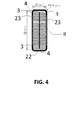
- the fabrication result is illustrated in a schematic way by a cut front view of the conductor bar 2 of Fig. 4 .
- the conductor tape 3 is attached to the conductor bar 2 at the bottom and the top of the conductor bar 2.
- the conductor tape 3 covers the hardened putty 4 in the area of the narrow sides 22 of the conductor bar 2.
- the conductor tape 3, which is a mica tape in an example, also covers the edges of the conductor bar 2 and small parts of the side faces next to the edges and remains at the conductor bar 2 after fabrication.
- the accurately defined radii of the Conductor bar 2 are shaped to 0.5mm to 3mm, in this example 2.5mm.
- Fig. 5 shows a schematic front view of a pressing mould 10 composed of nine parts with rounded edges to encompass and fabricate four conductor bars 2 similar to Fig. 3 .
- the upper part 15 of the pressing mould 10 has two cavities to enclose the top parts of two conductor bars 2.
- Three middle parts 14 are arranged to be positioned at the left, in the middle and at the right side of the two conductor bars 2.
- An intermediate part 17 is arranged to abut the middle parts 14 at the top and at the bottom. At the top and at the bottom the intermediate part 17 has each two cavities to enclose each two conductor bars 2.
- three middle parts 14 are also arranged below the intermediate part 17 to abut the intermediate part 17.
- the pressing mould 10 is closed at the bottom with the bottom part 13 which abuts the three middle parts 14 and which is shaped symmetrically to the upper part 15 to encompass two conductor bars 2.
- the inner faces of the pressing mould 10 are shaped to create conductor bars 2 with defined rounded edges 12.
- the pressing mould 10 is suitable for fabricating four conductor bars 2 simultaneously.
- the examples given refer to a conductor bar 2 as a Roebel bar, further examples are designable, especially a conductor bar 2 as part of a coil.
Landscapes
- Engineering & Computer Science (AREA)
- Manufacturing & Machinery (AREA)
- Power Engineering (AREA)
- Mechanical Engineering (AREA)
- Manufacture Of Motors, Generators (AREA)
- Processes Specially Adapted For Manufacturing Cables (AREA)
- Insulation, Fastening Of Motor, Generator Windings (AREA)
Priority Applications (1)
| Application Number | Priority Date | Filing Date | Title |
|---|---|---|---|
| EP15186389.1A EP3010124B1 (de) | 2014-10-15 | 2015-09-23 | Verfahren zur herstellung einer stromschiene |
Applications Claiming Priority (2)
| Application Number | Priority Date | Filing Date | Title |
|---|---|---|---|
| EP14189092 | 2014-10-15 | ||
| EP15186389.1A EP3010124B1 (de) | 2014-10-15 | 2015-09-23 | Verfahren zur herstellung einer stromschiene |
Publications (3)
| Publication Number | Publication Date |
|---|---|
| EP3010124A2 true EP3010124A2 (de) | 2016-04-20 |
| EP3010124A3 EP3010124A3 (de) | 2016-07-13 |
| EP3010124B1 EP3010124B1 (de) | 2019-11-27 |
Family
ID=51751947
Family Applications (1)
| Application Number | Title | Priority Date | Filing Date |
|---|---|---|---|
| EP15186389.1A Active EP3010124B1 (de) | 2014-10-15 | 2015-09-23 | Verfahren zur herstellung einer stromschiene |
Country Status (6)
| Country | Link |
|---|---|
| US (1) | US10090740B2 (de) |
| EP (1) | EP3010124B1 (de) |
| CN (1) | CN105529058B (de) |
| BR (1) | BR102015025572B1 (de) |
| CA (1) | CA2907310C (de) |
| ES (1) | ES2773963T3 (de) |
Families Citing this family (2)
| Publication number | Priority date | Publication date | Assignee | Title |
|---|---|---|---|---|
| US10510464B1 (en) * | 2017-12-20 | 2019-12-17 | Essex Group, Inc. | Continuously transposed conductors and assemblies |
| EP3706296B1 (de) * | 2018-01-31 | 2024-08-07 | Aisin Corporation | Verfahren zur herstellung eines ankers und vorrichtung zur herstellung eines ankers |
Family Cites Families (9)
| Publication number | Priority date | Publication date | Assignee | Title |
|---|---|---|---|---|
| US3840416A (en) * | 1971-03-31 | 1974-10-08 | Licentia Gmbh | Method of producing waterproof electrical coils |
| JPS63206134A (ja) * | 1987-02-23 | 1988-08-25 | Toshiba Corp | 回転電機巻線 |
| DE19543122A1 (de) * | 1995-11-18 | 1997-05-22 | Asea Brown Boveri | Leiterstab |
| US6228494B1 (en) * | 1998-12-02 | 2001-05-08 | Siemens Westinghouse Power Corporation | Method to reduce partial discharge in high voltage stator coil's roebel filler |
| US6559384B1 (en) * | 1998-12-18 | 2003-05-06 | Electrolock, Inc. | Conductive filler |
| JP2001061247A (ja) * | 1999-08-23 | 2001-03-06 | Toshiba Corp | 回転電機の固定子コイル |
| US6663816B2 (en) * | 2002-01-31 | 2003-12-16 | General Electric Company | Method of making a dynamoelectric machine conductor bar and method of making a conductor bar dynamoelectric machine |
| DE10304025A1 (de) * | 2003-02-01 | 2004-08-05 | Alstom Technology Ltd | Roebelstab für eine elektrischen Maschine sowie Verfahren zum Herstellen eines solchen Roebelstabes |
| EP2348615A1 (de) * | 2010-01-22 | 2011-07-27 | Alstom Technology Ltd | Leiterstab für elektrische Maschinen |
-
2015
- 2015-09-23 ES ES15186389T patent/ES2773963T3/es active Active
- 2015-09-23 EP EP15186389.1A patent/EP3010124B1/de active Active
- 2015-10-06 CA CA2907310A patent/CA2907310C/en active Active
- 2015-10-07 BR BR102015025572-1A patent/BR102015025572B1/pt active IP Right Grant
- 2015-10-13 US US14/881,425 patent/US10090740B2/en active Active
- 2015-10-15 CN CN201510663613.8A patent/CN105529058B/zh active Active
Non-Patent Citations (1)
| Title |
|---|
| None |
Also Published As
| Publication number | Publication date |
|---|---|
| EP3010124A3 (de) | 2016-07-13 |
| EP3010124B1 (de) | 2019-11-27 |
| CN105529058A (zh) | 2016-04-27 |
| ES2773963T3 (es) | 2020-07-15 |
| CA2907310A1 (en) | 2016-04-15 |
| US10090740B2 (en) | 2018-10-02 |
| CA2907310C (en) | 2023-03-21 |
| BR102015025572B1 (pt) | 2022-03-29 |
| US20160111946A1 (en) | 2016-04-21 |
| BR102015025572A2 (pt) | 2016-09-27 |
| CN105529058B (zh) | 2019-11-05 |
Similar Documents
| Publication | Publication Date | Title |
|---|---|---|
| US7346974B2 (en) | Method for producing a conductor bar of transposed stranded conductors | |
| KR102046187B1 (ko) | 연속 전치 전도체 | |
| US7893357B2 (en) | Roebel winding with conductive felt | |
| KR101950528B1 (ko) | 연속 전치 전도체 | |
| JP3881520B2 (ja) | コイル装置 | |
| HRP960469A2 (en) | A lighting rod | |
| US3662199A (en) | High voltage insulated coil and machine utilizing the same | |
| KR20160112959A (ko) | 전기 기기용 권선 | |
| CN111512520A (zh) | 电机的子导线的绝缘 | |
| US10424984B2 (en) | Rotating electrical machine coil, production method of rotating electrical machine coil, and rotating electrical machine | |
| US10090740B2 (en) | Method for fabrication of a conductor bar | |
| KR20120049277A (ko) | 리드아웃 튜브 | |
| CA2469529C (en) | System and method for improving connectivity of multiple parallel connectors | |
| CN108736672B (zh) | 空冷水轮发电机真空压力浸渍定子线棒制造方法 | |
| EP1544985A2 (de) | Spule für elektrische Maschinen | |
| EP2594013B1 (de) | Verfahren zum formen von isolierten spulen für eine elektrodynamische maschine | |
| CN208656534U (zh) | 用于电机的槽绝缘结构 | |
| KR101879755B1 (ko) | 전기 와인딩 제조 방법 및 전기 도체 | |
| JP2010226814A (ja) | 回転電機の回転子 | |
| JPH08163838A (ja) | 高圧回転電機の固定子コイルの製造方法 | |
| CN105917552A (zh) | 绝缘系统、定子、电机、尤其涡轮发电机,以及用于使导电元件绝缘的方法 | |
| EP0409479B1 (de) | Verfahren zur herstellung eines elektromagnetischen geraets | |
| JP2005341728A (ja) | 回転電機の固定子巻線 | |
| JP2000023404A (ja) | 固定子巻線の直列接続部の絶縁構造 | |
| JPS59153447A (ja) | 回転電機コイルの製造法 |
Legal Events
| Date | Code | Title | Description |
|---|---|---|---|
| PUAI | Public reference made under article 153(3) epc to a published international application that has entered the european phase |
Free format text: ORIGINAL CODE: 0009012 |
|
| AK | Designated contracting states |
Kind code of ref document: A2 Designated state(s): AL AT BE BG CH CY CZ DE DK EE ES FI FR GB GR HR HU IE IS IT LI LT LU LV MC MK MT NL NO PL PT RO RS SE SI SK SM TR |
|
| AX | Request for extension of the european patent |
Extension state: BA ME |
|
| PUAL | Search report despatched |
Free format text: ORIGINAL CODE: 0009013 |
|
| AK | Designated contracting states |
Kind code of ref document: A3 Designated state(s): AL AT BE BG CH CY CZ DE DK EE ES FI FR GB GR HR HU IE IS IT LI LT LU LV MC MK MT NL NO PL PT RO RS SE SI SK SM TR |
|
| AX | Request for extension of the european patent |
Extension state: BA ME |
|
| RIC1 | Information provided on ipc code assigned before grant |
Ipc: B29C 43/00 20060101ALI20160609BHEP Ipc: H02K 3/40 20060101ALN20160609BHEP Ipc: B29C 43/18 20060101ALI20160609BHEP Ipc: H02K 3/14 20060101ALN20160609BHEP Ipc: B29C 43/36 20060101ALI20160609BHEP Ipc: H02K 15/10 20060101AFI20160609BHEP Ipc: H02K 15/12 20060101ALI20160609BHEP Ipc: H01B 13/06 20060101ALI20160609BHEP |
|
| STAA | Information on the status of an ep patent application or granted ep patent |
Free format text: STATUS: REQUEST FOR EXAMINATION WAS MADE |
|
| 17P | Request for examination filed |
Effective date: 20170113 |
|
| RBV | Designated contracting states (corrected) |
Designated state(s): AL AT BE BG CH CY CZ DE DK EE ES FI FR GB GR HR HU IE IS IT LI LT LU LV MC MK MT NL NO PL PT RO RS SE SI SK SM TR |
|
| RAP1 | Party data changed (applicant data changed or rights of an application transferred) |
Owner name: GE RENEWABLE TECHNOLOGIES |
|
| STAA | Information on the status of an ep patent application or granted ep patent |
Free format text: STATUS: EXAMINATION IS IN PROGRESS |
|
| 17Q | First examination report despatched |
Effective date: 20170616 |
|
| GRAP | Despatch of communication of intention to grant a patent |
Free format text: ORIGINAL CODE: EPIDOSNIGR1 |
|
| STAA | Information on the status of an ep patent application or granted ep patent |
Free format text: STATUS: GRANT OF PATENT IS INTENDED |
|
| RIC1 | Information provided on ipc code assigned before grant |
Ipc: H02K 3/40 20060101ALN20190517BHEP Ipc: B29C 43/36 20060101ALI20190517BHEP Ipc: B29L 31/00 20060101ALI20190517BHEP Ipc: H02K 15/12 20060101ALI20190517BHEP Ipc: H02K 15/10 20060101AFI20190517BHEP Ipc: H01B 13/06 20060101ALI20190517BHEP Ipc: B29C 43/00 20060101ALI20190517BHEP Ipc: B29C 43/18 20060101ALI20190517BHEP Ipc: H02K 3/14 20060101ALN20190517BHEP |
|
| INTG | Intention to grant announced |
Effective date: 20190621 |
|
| GRAS | Grant fee paid |
Free format text: ORIGINAL CODE: EPIDOSNIGR3 |
|
| GRAA | (expected) grant |
Free format text: ORIGINAL CODE: 0009210 |
|
| STAA | Information on the status of an ep patent application or granted ep patent |
Free format text: STATUS: THE PATENT HAS BEEN GRANTED |
|
| AK | Designated contracting states |
Kind code of ref document: B1 Designated state(s): AL AT BE BG CH CY CZ DE DK EE ES FI FR GB GR HR HU IE IS IT LI LT LU LV MC MK MT NL NO PL PT RO RS SE SI SK SM TR |
|
| REG | Reference to a national code |
Ref country code: GB Ref legal event code: FG4D |
|
| REG | Reference to a national code |
Ref country code: CH Ref legal event code: EP |
|
| REG | Reference to a national code |
Ref country code: AT Ref legal event code: REF Ref document number: 1207846 Country of ref document: AT Kind code of ref document: T Effective date: 20191215 |
|
| REG | Reference to a national code |
Ref country code: DE Ref legal event code: R096 Ref document number: 602015042402 Country of ref document: DE |
|
| REG | Reference to a national code |
Ref country code: IE Ref legal event code: FG4D |
|
| REG | Reference to a national code |
Ref country code: CH Ref legal event code: NV Representative=s name: VALIPAT S.A. C/O BOVARD SA NEUCHATEL, CH |
|
| REG | Reference to a national code |
Ref country code: NL Ref legal event code: MP Effective date: 20191127 |
|
| REG | Reference to a national code |
Ref country code: LT Ref legal event code: MG4D |
|
| PG25 | Lapsed in a contracting state [announced via postgrant information from national office to epo] |
Ref country code: GR Free format text: LAPSE BECAUSE OF FAILURE TO SUBMIT A TRANSLATION OF THE DESCRIPTION OR TO PAY THE FEE WITHIN THE PRESCRIBED TIME-LIMIT Effective date: 20200228 Ref country code: NO Free format text: LAPSE BECAUSE OF FAILURE TO SUBMIT A TRANSLATION OF THE DESCRIPTION OR TO PAY THE FEE WITHIN THE PRESCRIBED TIME-LIMIT Effective date: 20200227 Ref country code: BG Free format text: LAPSE BECAUSE OF FAILURE TO SUBMIT A TRANSLATION OF THE DESCRIPTION OR TO PAY THE FEE WITHIN THE PRESCRIBED TIME-LIMIT Effective date: 20200227 Ref country code: LT Free format text: LAPSE BECAUSE OF FAILURE TO SUBMIT A TRANSLATION OF THE DESCRIPTION OR TO PAY THE FEE WITHIN THE PRESCRIBED TIME-LIMIT Effective date: 20191127 Ref country code: FI Free format text: LAPSE BECAUSE OF FAILURE TO SUBMIT A TRANSLATION OF THE DESCRIPTION OR TO PAY THE FEE WITHIN THE PRESCRIBED TIME-LIMIT Effective date: 20191127 Ref country code: SE Free format text: LAPSE BECAUSE OF FAILURE TO SUBMIT A TRANSLATION OF THE DESCRIPTION OR TO PAY THE FEE WITHIN THE PRESCRIBED TIME-LIMIT Effective date: 20191127 Ref country code: LV Free format text: LAPSE BECAUSE OF FAILURE TO SUBMIT A TRANSLATION OF THE DESCRIPTION OR TO PAY THE FEE WITHIN THE PRESCRIBED TIME-LIMIT Effective date: 20191127 Ref country code: NL Free format text: LAPSE BECAUSE OF FAILURE TO SUBMIT A TRANSLATION OF THE DESCRIPTION OR TO PAY THE FEE WITHIN THE PRESCRIBED TIME-LIMIT Effective date: 20191127 |
|
| PG25 | Lapsed in a contracting state [announced via postgrant information from national office to epo] |
Ref country code: RS Free format text: LAPSE BECAUSE OF FAILURE TO SUBMIT A TRANSLATION OF THE DESCRIPTION OR TO PAY THE FEE WITHIN THE PRESCRIBED TIME-LIMIT Effective date: 20191127 Ref country code: HR Free format text: LAPSE BECAUSE OF FAILURE TO SUBMIT A TRANSLATION OF THE DESCRIPTION OR TO PAY THE FEE WITHIN THE PRESCRIBED TIME-LIMIT Effective date: 20191127 Ref country code: IS Free format text: LAPSE BECAUSE OF FAILURE TO SUBMIT A TRANSLATION OF THE DESCRIPTION OR TO PAY THE FEE WITHIN THE PRESCRIBED TIME-LIMIT Effective date: 20200327 |
|
| PG25 | Lapsed in a contracting state [announced via postgrant information from national office to epo] |
Ref country code: AL Free format text: LAPSE BECAUSE OF FAILURE TO SUBMIT A TRANSLATION OF THE DESCRIPTION OR TO PAY THE FEE WITHIN THE PRESCRIBED TIME-LIMIT Effective date: 20191127 |
|
| REG | Reference to a national code |
Ref country code: ES Ref legal event code: FG2A Ref document number: 2773963 Country of ref document: ES Kind code of ref document: T3 Effective date: 20200715 |
|
| PG25 | Lapsed in a contracting state [announced via postgrant information from national office to epo] |
Ref country code: DK Free format text: LAPSE BECAUSE OF FAILURE TO SUBMIT A TRANSLATION OF THE DESCRIPTION OR TO PAY THE FEE WITHIN THE PRESCRIBED TIME-LIMIT Effective date: 20191127 Ref country code: EE Free format text: LAPSE BECAUSE OF FAILURE TO SUBMIT A TRANSLATION OF THE DESCRIPTION OR TO PAY THE FEE WITHIN THE PRESCRIBED TIME-LIMIT Effective date: 20191127 Ref country code: PT Free format text: LAPSE BECAUSE OF FAILURE TO SUBMIT A TRANSLATION OF THE DESCRIPTION OR TO PAY THE FEE WITHIN THE PRESCRIBED TIME-LIMIT Effective date: 20200419 Ref country code: CZ Free format text: LAPSE BECAUSE OF FAILURE TO SUBMIT A TRANSLATION OF THE DESCRIPTION OR TO PAY THE FEE WITHIN THE PRESCRIBED TIME-LIMIT Effective date: 20191127 Ref country code: RO Free format text: LAPSE BECAUSE OF FAILURE TO SUBMIT A TRANSLATION OF THE DESCRIPTION OR TO PAY THE FEE WITHIN THE PRESCRIBED TIME-LIMIT Effective date: 20191127 |
|
| REG | Reference to a national code |
Ref country code: DE Ref legal event code: R097 Ref document number: 602015042402 Country of ref document: DE |
|
| PG25 | Lapsed in a contracting state [announced via postgrant information from national office to epo] |
Ref country code: SK Free format text: LAPSE BECAUSE OF FAILURE TO SUBMIT A TRANSLATION OF THE DESCRIPTION OR TO PAY THE FEE WITHIN THE PRESCRIBED TIME-LIMIT Effective date: 20191127 Ref country code: SM Free format text: LAPSE BECAUSE OF FAILURE TO SUBMIT A TRANSLATION OF THE DESCRIPTION OR TO PAY THE FEE WITHIN THE PRESCRIBED TIME-LIMIT Effective date: 20191127 |
|
| PLBE | No opposition filed within time limit |
Free format text: ORIGINAL CODE: 0009261 |
|
| STAA | Information on the status of an ep patent application or granted ep patent |
Free format text: STATUS: NO OPPOSITION FILED WITHIN TIME LIMIT |
|
| 26N | No opposition filed |
Effective date: 20200828 |
|
| PG25 | Lapsed in a contracting state [announced via postgrant information from national office to epo] |
Ref country code: PL Free format text: LAPSE BECAUSE OF FAILURE TO SUBMIT A TRANSLATION OF THE DESCRIPTION OR TO PAY THE FEE WITHIN THE PRESCRIBED TIME-LIMIT Effective date: 20191127 Ref country code: SI Free format text: LAPSE BECAUSE OF FAILURE TO SUBMIT A TRANSLATION OF THE DESCRIPTION OR TO PAY THE FEE WITHIN THE PRESCRIBED TIME-LIMIT Effective date: 20191127 |
|
| PG25 | Lapsed in a contracting state [announced via postgrant information from national office to epo] |
Ref country code: IT Free format text: LAPSE BECAUSE OF FAILURE TO SUBMIT A TRANSLATION OF THE DESCRIPTION OR TO PAY THE FEE WITHIN THE PRESCRIBED TIME-LIMIT Effective date: 20191127 |
|
| PG25 | Lapsed in a contracting state [announced via postgrant information from national office to epo] |
Ref country code: MC Free format text: LAPSE BECAUSE OF FAILURE TO SUBMIT A TRANSLATION OF THE DESCRIPTION OR TO PAY THE FEE WITHIN THE PRESCRIBED TIME-LIMIT Effective date: 20191127 |
|
| GBPC | Gb: european patent ceased through non-payment of renewal fee |
Effective date: 20200923 |
|
| REG | Reference to a national code |
Ref country code: BE Ref legal event code: MM Effective date: 20200930 |
|
| PG25 | Lapsed in a contracting state [announced via postgrant information from national office to epo] |
Ref country code: LU Free format text: LAPSE BECAUSE OF NON-PAYMENT OF DUE FEES Effective date: 20200923 |
|
| PG25 | Lapsed in a contracting state [announced via postgrant information from national office to epo] |
Ref country code: FR Free format text: LAPSE BECAUSE OF NON-PAYMENT OF DUE FEES Effective date: 20200930 |
|
| PG25 | Lapsed in a contracting state [announced via postgrant information from national office to epo] |
Ref country code: BE Free format text: LAPSE BECAUSE OF NON-PAYMENT OF DUE FEES Effective date: 20200930 Ref country code: GB Free format text: LAPSE BECAUSE OF NON-PAYMENT OF DUE FEES Effective date: 20200923 Ref country code: IE Free format text: LAPSE BECAUSE OF NON-PAYMENT OF DUE FEES Effective date: 20200923 |
|
| REG | Reference to a national code |
Ref country code: AT Ref legal event code: UEP Ref document number: 1207846 Country of ref document: AT Kind code of ref document: T Effective date: 20191127 |
|
| PG25 | Lapsed in a contracting state [announced via postgrant information from national office to epo] |
Ref country code: TR Free format text: LAPSE BECAUSE OF FAILURE TO SUBMIT A TRANSLATION OF THE DESCRIPTION OR TO PAY THE FEE WITHIN THE PRESCRIBED TIME-LIMIT Effective date: 20191127 Ref country code: MT Free format text: LAPSE BECAUSE OF FAILURE TO SUBMIT A TRANSLATION OF THE DESCRIPTION OR TO PAY THE FEE WITHIN THE PRESCRIBED TIME-LIMIT Effective date: 20191127 Ref country code: CY Free format text: LAPSE BECAUSE OF FAILURE TO SUBMIT A TRANSLATION OF THE DESCRIPTION OR TO PAY THE FEE WITHIN THE PRESCRIBED TIME-LIMIT Effective date: 20191127 |
|
| PG25 | Lapsed in a contracting state [announced via postgrant information from national office to epo] |
Ref country code: MK Free format text: LAPSE BECAUSE OF FAILURE TO SUBMIT A TRANSLATION OF THE DESCRIPTION OR TO PAY THE FEE WITHIN THE PRESCRIBED TIME-LIMIT Effective date: 20191127 |
|
| P01 | Opt-out of the competence of the unified patent court (upc) registered |
Effective date: 20230522 |
|
| REG | Reference to a national code |
Ref country code: CH Ref legal event code: U11 Free format text: ST27 STATUS EVENT CODE: U-0-0-U10-U11 (AS PROVIDED BY THE NATIONAL OFFICE) Effective date: 20251001 |
|
| PGFP | Annual fee paid to national office [announced via postgrant information from national office to epo] |
Ref country code: DE Payment date: 20250820 Year of fee payment: 11 |
|
| PGFP | Annual fee paid to national office [announced via postgrant information from national office to epo] |
Ref country code: AT Payment date: 20250822 Year of fee payment: 11 |
|
| PGFP | Annual fee paid to national office [announced via postgrant information from national office to epo] |
Ref country code: CH Payment date: 20251001 Year of fee payment: 11 |
|
| PGFP | Annual fee paid to national office [announced via postgrant information from national office to epo] |
Ref country code: ES Payment date: 20251001 Year of fee payment: 11 |