EP3010143A1 - Procédé de commande d'ondulation de force d'un générateur - Google Patents
Procédé de commande d'ondulation de force d'un générateur Download PDFInfo
- Publication number
- EP3010143A1 EP3010143A1 EP14188843.8A EP14188843A EP3010143A1 EP 3010143 A1 EP3010143 A1 EP 3010143A1 EP 14188843 A EP14188843 A EP 14188843A EP 3010143 A1 EP3010143 A1 EP 3010143A1
- Authority
- EP
- European Patent Office
- Prior art keywords
- signal
- indicative
- generator
- input signal
- output signal
- Prior art date
- Legal status (The legal status is an assumption and is not a legal conclusion. Google has not performed a legal analysis and makes no representation as to the accuracy of the status listed.)
- Granted
Links
Images

Classifications
-
- H—ELECTRICITY
- H02—GENERATION; CONVERSION OR DISTRIBUTION OF ELECTRIC POWER
- H02P—CONTROL OR REGULATION OF ELECTRIC MOTORS, ELECTRIC GENERATORS OR DYNAMO-ELECTRIC CONVERTERS; CONTROLLING TRANSFORMERS, REACTORS OR CHOKE COILS
- H02P21/00—Arrangements or methods for the control of electric machines by vector control, e.g. by control of field orientation
- H02P21/05—Arrangements or methods for the control of electric machines by vector control, e.g. by control of field orientation specially adapted for damping motor oscillations, e.g. for reducing hunting
-
- H—ELECTRICITY
- H02—GENERATION; CONVERSION OR DISTRIBUTION OF ELECTRIC POWER
- H02J—ELECTRIC POWER NETWORKS; CIRCUIT ARRANGEMENTS OR SYSTEMS FOR SUPPLYING OR DISTRIBUTING ELECTRIC POWER; SYSTEMS FOR STORING ELECTRIC ENERGY
- H02J3/00—Circuit arrangements for AC mains or AC distribution networks
- H02J3/38—Arrangements for feeding a single network from two or more generators or sources in parallel; Arrangements for feeding already energised networks from additional generators or sources in parallel
- H02J3/381—Dispersed generators
-
- H—ELECTRICITY
- H02—GENERATION; CONVERSION OR DISTRIBUTION OF ELECTRIC POWER
- H02P—CONTROL OR REGULATION OF ELECTRIC MOTORS, ELECTRIC GENERATORS OR DYNAMO-ELECTRIC CONVERTERS; CONTROLLING TRANSFORMERS, REACTORS OR CHOKE COILS
- H02P21/00—Arrangements or methods for the control of electric machines by vector control, e.g. by control of field orientation
- H02P21/22—Current control, e.g. using a current control loop
-
- H—ELECTRICITY
- H02—GENERATION; CONVERSION OR DISTRIBUTION OF ELECTRIC POWER
- H02P—CONTROL OR REGULATION OF ELECTRIC MOTORS, ELECTRIC GENERATORS OR DYNAMO-ELECTRIC CONVERTERS; CONTROLLING TRANSFORMERS, REACTORS OR CHOKE COILS
- H02P29/00—Arrangements for regulating or controlling electric motors, appropriate for both AC and DC motors
- H02P29/50—Reduction of harmonics
-
- H—ELECTRICITY
- H02—GENERATION; CONVERSION OR DISTRIBUTION OF ELECTRIC POWER
- H02J—ELECTRIC POWER NETWORKS; CIRCUIT ARRANGEMENTS OR SYSTEMS FOR SUPPLYING OR DISTRIBUTING ELECTRIC POWER; SYSTEMS FOR STORING ELECTRIC ENERGY
- H02J2101/00—Supply or distribution of decentralised, dispersed or local electric power generation
- H02J2101/20—Dispersed power generation using renewable energy sources
- H02J2101/28—Wind energy
Definitions
- the present invention relates to the field of wind turbines, more particular to the field of permanent magnet machines.
- One approach is to design the generator appropriately to reduce harmonics in both air-gap torque and radial force pressure so that acoustic noise and vibration can be reduced.
- torque ripples can be greatly reduced by using proper shaping of magnets.
- the performance of this approach is limited.
- Another approach to reduce noise and vibration is to design mechanical parts of the generator, in such a way, that all resonance frequencies are out of the range that can be excited by torque and radial force pressure ripples.
- a method for providing a harmonic current reference comprising: Obtaining a first input signal indicative for a radial force ripple of a generator; obtaining a second input signal indicative for a reference harmonic radial force.
- an electrical frequency of the generator may be used.
- the transformation procedure according to the invention may be a regulator procedure or a signal processing procedure as well.
- This aspect of the invention is based on the idea that by measuring or estimating force ripples of the generator in a very efficient way and using them as a feedback source, both, torque ripples and radial force ripples may be minimized.
- the first transformation procedure comprises: determining a first error signal by subtracting the first internal signal from the second input signal, the first error signal being indicative for a regulation error of the first internal signal; and determining the first output signal by a third transformation procedure, making use of the first error signal.
- the second transformation procedure comprises: determining a second error signal by subtracting the second internal signal from the fourth input signal, the second error signal being indicative for a regulation error of the second internal signal; and determining the second output signal by a fourth transformation procedure, making use of the second error signal.
- the third transformation procedure comprises: splitting the first error signal into two identical split first error signals; providing a third internal signal by modifying a first of the two identical split first error signals; and determining the first output signal by a fifth transformation procedure, making use of the first error signal and the third internal signal.
- the fourth transformation procedure comprises: Splitting the second error signal into two identical split second error signals; providing a fourth internal signal by modifying a first of the two identical split second error signals; and determining the second output signal by a sixth transformation procedure, making use of the second error signal and the fourth internal signal.
- the fifth transformation procedure comprises: making use of the fifth input signal.
- the sixth transformation procedure comprises: making use of the fifth input signal.
- modifying the first of the two identical split first error signals comprises: applying a first phase shifting procedure, in particular a 90 degrees phase shifting procedure.
- modifying the first of the two identical split second error signals comprises: applying a second phase shifting procedure, in particular a 90 degrees phase shifting procedure.
- the third transformation procedure comprises: applying a first trigonometric function.
- the fourth transformation procedure comprises: applying a second trigonometric function.
- the method moreover comprises: modifying the second of the two identical split first error signals; and modifying the second of the two identical split second error signals.
- modifying the second of the two identical split first error signals comprises applying a third trigonometric function
- modifying the second of the two identical split second error signals comprises applying a fourth trigonometric function.
- the second trigonometric function equals the first trigonometric function
- the fourth trigonometric function equals the third trigonometric function
- the third trigonometric function is different from the first trigonometric function
- the third transformation procedure comprises: resonance regulating the first error signal by applying a first transfer function to the first error signal.
- the fourth transformation procedure comprises: resonance regulating the second error signal by applying a second transfer function to the second error signal.
- the second transfer function equals the first transfer function.
- a force ripple control method for controlling force ripples of a generator, the force ripple control method comprising: performing a method for providing a certain harmonic current reference according to any of the claims according to the first aspect of the invention; and determining a third output signal and a fourth output signal depending on the fifth input signal, the first output signal, the second output signal and a set of current signals.
- the set of current signals is indicative for a first current, a second current, and a third current each generated by the generator.
- the third output signal is indicative for a harmonic voltage command for the first axle of the synchronous rotating frame.
- the fourth output signal is indicative for a harmonic voltage command for the second axle of the synchronous rotating frame.
- the force ripple control method comprises: determining a seventh output signal by adding the third output signal to a fifth output signal.
- the fifth output signal is indicative for a first fundamental voltage command of a current controller of a frequency converter for the generator.
- the seventh output signal is indicative for a voltage command at the first axle of the synchronous rotating frame, for controlling a radial force ripple of the generator.
- the force ripple control method comprises: determining an eighth output signal by adding the fourth output signal to a sixth output signal.
- the sixth output signal is indicative for a second fundamental voltage command of the current controller of the frequency converter for the generator.
- the eighth output signal is indicative for a voltage command at the second axle of the synchronous rotating frame, for controlling a tangential force ripple of the generator.
- This embodiment of the invention is based on the idea that a frequency converter may inject harmonic currents to the machine stator so that both, torque ripples and radial force ripples may be minimized. Therefore, this may aid in reducing acoustic noise and vibration of a permanent magnet machine, by minimizing torque ripples as well as radial force pressure ripples. Moreover, nearly no additional costs may be spent as the invention does allow for only minimal change requirements for hardware of available products already in the market.
- a harmonic current reference controller device for controlling force ripples of a generator
- the harmonic current reference controller device comprising: a first input for obtaining a first input signal indicative for a radial force ripple of a generator; a second input for obtaining a second input signal indicative for a reference harmonic generator radial force; a third input for obtaining a third input signal indicative for a tangential force ripple of the generator; a fourth input for obtaining a fourth input signal indicative for a reference harmonic generator tangential force; a fifth input for obtaining a fifth input signal indicative for an electrical angle of the generator; and a first filter unit for determining a first internal signal by filtering the first input signal by taking into account the fifth input signal.
- the first internal signal is indicative for a radial force ripple comprising only a radial component at a certain harmonic of a generator current.
- the current reference controller device comprises: a second filter unit for determining a second internal signal by filtering the third input signal by taking into account the fifth input signal. Therein, the second internal signal is indicative for a tangential force ripple comprising only a tangential component at the certain harmonic of the generator current.
- the current reference controller device comprises: a first transformation unit for determining a first output signal by a first transformation procedure making use of the second input signal and the first internal signal. Therein, the first output signal being indicative for a certain harmonic current reference for a first axle of a synchronous rotating frame.
- the current reference controller device comprises: A second transformation unit for determining a second output signal by a second transformation procedure making use of the fourth input signal and the second internal signal. Therein, the second output signal being indicative for a certain harmonic current reference for a second axle of the synchronous rotating frame.
- This aspect of the invention is based on the idea that nearly no additional costs may be spent as the invention does allow for only minimal change requirements for hardware of available products already in the market, like a low cost harmonic current reference controller device as provided by the invention compared to the very high costs for manufacturing, transporting and assembling a wind turbine at its area of activity.
- the device is adapted for performing a method for providing a harmonic current reference according to any of the claims according to the first aspect of the invention.
- This embodiment of the invention is based on the idea that by applying the methods provided by the invention to the controller device, a very efficient way of providing minimizing of torque ripples and radial force ripples may be made available.
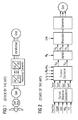
- Figure 1 shows a schematically drawing of a state of the art variable speed wind turbine.
- a variable speed wind turbine which consists of a rotor, an optional gearbox, an ac-generator, a frequency converter and a transformer.
- the frequency converter is used to interface the ac-power from the generator to the power grid also shown in figure 1 .
- the frequency converter has generator-side converter modules and grid-side converter modules with DC-link capacitors in between. Both generator-side converter modules and grid-side converter modules may be power electronics devices made of PWM-controlled IGBTs or other devices.
- Figure 2 shows a schematically drawing of a state of the art generator-side controller of a frequency converter being part of the wind turbine shown in figure 1 .
- a current reference calculation block is used to provide a fundamental current reference for a synchronous rotating d-q frame of the generator.
- the input to the block may be for example a power/torque reference, a generator voltage, a dc link voltage and a power/torque as shown in figure 2 . It is also possible to only use some combinations of these signals as inputs.
- Current references may be calculated based on a generator voltage controller values, like a maximum torque per ampere requirements and the like, depending on the application requirements.
- the Current Controller block in Figure 2 is a closed-loop feedback regulation of a generator current in the rotating d-q frame. For a better dynamic performance and decoupling, voltage feed-forward may also be used in this block.
- the present invention provided in this application may act as an add-on feature to such a current controller block.
- Exemplary embodiment details of the present invention like a force ripple controller, an interacting of such a current controller block with a provided force ripple controller and corresponding underlying exemplary methods of the present invention are shown in figures 3 to 7 .
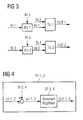
- Figure 3 shows a schematically drawing of a proposed force ripple controller for a wind turbine as shown in figure 1 according to an exemplary embodiment of the invention.
- a harmonic current reference controller device for controlling force ripples of a generator, the controller device comprising: a first input for obtaining a first input signal IN1 indicative for a radial force ripple of a generator; a second input for obtaining a second input signal IN2 indicative for a reference harmonic generator radial force; a third input for obtaining a third input signal IN3 indicative for a tangential force ripple of the generator; a fourth input for obtaining a fourth input signal IN4 indicative for a reference harmonic generator tangential force; a fifth input for obtaining a fifth input signal IN5 indicative for an electrical angle of the generator; a first filter unit FU1 for determining a first internal signal int1 by filtering the first input signal IN1 by taking into account the fifth input signal IN5, the first internal signal int1 being indicative for a radial force ripple comprising only a radial component at a certain harmonic of a generator current; a second filter unit FU2 for determining a second internal signal int2 by filter
- radial force ripples are controlled by the first output signal OUT1, which may be a harmonic current for the first axle of a synchronous rotating frame, which may be the d-axle, while tangential force ripples / torque ripples are controlled by the second output OUT2, which may be a harmonic current for the second axle of the synchronous rotating frame, which may be the q-axle.
- the estimated/measured force/torque may pass an adaptive filter so that Nth harmonics in force/torque may be higher than harmonics at other frequencies.
- the Nth force/torque ripples and their commands may be inputs to the force ripple regulators.
- the force ripple regulators then may regulate force ripples to follow their commands by outputting proper harmonic current commands OUT1, OUT2, one for the Nth harmonic radial force ripple OUT 1, and one for the Nth harmonic torque force ripple OUT2, for each Nth harmonic force/torque ripples.
- the device is adapted for performing a method for providing a harmonic current reference according to any of the provided methods according to the invention.
- Figure 3 moreover shows the method comprising: filtering FU1 a radial force ripple IN1 of the generator by applying an electrical angle IN5 of the generator to the radial force ripple IN1, such as to receive a filtered radial force ripple int1 comprising only a radial component at a certain harmonic of a generator current; filtering a tangential force ripple IN3 of the generator by applying the electrical angle IN5 of the generator to the tangential force ripple IN3, such as to receive a filtered tangential force ripple int2 comprising only a tangential component at the certain harmonic of the generator current; regulating TU1 the filtered radial force ripple int1 by applying a reference certain harmonic generator radial force IN2 to the filtered radial force ripple int1, such as to receive a certain harmonic current reference OUT1 for a first axle of a synchronous rotating frame; and regulating the filtered tangential force ripple int2 by applying a reference certain harmonic generator tangential force IN4 to the filtered tangential force ripple
- Figures 4 , 5 and 6 each show another force ripple regulator unit as the first and the second transformation unit TU1, TU2 as part of the harmonic current reference controller device as shown in figure 3 according to exemplary embodiments of the invention.
- the error of the force ripple is calculated and a close loop regulation of the force ripple is made so that the Nth harmonic force ripple will follow Nth harmonic force ripple commands OUT 1, OUT2.
- the regulators are used to control the force ripple error to zero.
- the exemplary embodiments shown in figures 4 to 6 rely on a method for providing a harmonic current reference, in particular for controlling force ripples of a generator, the method comprising: obtaining a first input signal IN1 indicative for a radial force ripple of a generator; obtaining a second input signal IN2 indicative for a reference harmonic generator radial force; obtaining a third input signal IN3 indicative for a tangential force ripple of the generator; obtaining a fourth input signal IN4 indicative for a reference harmonic generator tangential force; obtaining a fifth input signal IN5 indicative for an electrical angle of the generator; determining a first internal signal int1 by filtering the first input signal IN1 with taking into account the fifth input signal IN5, the first internal signal int1 being indicative for a radial force
- the force ripple regulator TU1, TU2 comprises the first transformation procedure TP1, the first transformation procedure TP1 comprising: determining a first error signal err1, by subtracting the first internal signal int1 from the second input signal IN2, the first error signal err1 being indicative for a regulation error of the first internal signal IN1, and determining the first output signal OUT1 by a third transformation procedure TP3, making use of the first error signal err1.
- the force ripple regulator TU1, TU2 comprises the second transformation procedure TP2, the second transformation procedure TP2 comprising: determining a second error signal err2, by subtracting the second internal signal int2 from the fourth input signal IN4, the second error signal err2 being indicative for a regulation error of the second internal signal int2; and determining the second output signal OUT2, by a fourth transformation procedure TP4, making use of the second error signal err2.
- Figure 4 shows a schematically drawing of a force ripple regulator TU1, TU2 of the force ripple controller as shown in figure 3 according to an exemplary embodiment of the invention.
- Figure 4 shows an exemplary embodiment, wherein the force ripple regulator is using a resonant regulator.
- a resonant controller may regulate any harmonic at a certain frequency.
- the third transformation procedure TP3 comprises resonance regulating the first error signal err1 by applying a first transfer function to the first error signal err1.
- the fourth transformation procedure TP4 comprises resonance regulating the second error signal err2 by applying a second transfer function to the second error signal err2.
- the second transfer function equals the first transfer function.
- Figure 4 moreover shows the method comprising: regulating the filtered radial force ripple comprises: determining a regulation error of the filtered radial force ripple by adding the reference certain harmonic generator radial force and subtracting the filtered radial force ripple; resonance regulating the regulation error of the filtered radial force ripple by use of a first transfer function, such as to receive the certain harmonic current reference for the first axle of the synchronous rotating frame; and wherein regulating the filtered tangential force ripple comprises: determining a regulation error of the filtered tangential force ripple by adding the reference certain harmonic generator tangential force and subtracting the filtered tangential force ripple; resonance regulating the regulation error of the filtered tangential force ripple by use of a second transfer function, such as to receive the certain harmonic current reference for the second axle of the synchronous rotating frame. Moreover, the second transfer function equals the first transfer function.
- FIG. 5 Exemplary embodiments using a force ripple regulator TU1, TU2 based on a vector control principal are shown in figure 5 and figure 6 .
- the third transformation procedure TP3 comprises: splitting the first error signal err1 into two identical split first error signals err1, err1; providing a third internal signal int3 by modifying a first of the two identical split first error signals err1, err1; and determining the first output signal OUT1 by a fifth transformation procedure TP5, making use of the first error signal err1 and the third internal signal int3.
- the fourth transformation procedure TP4 comprises: splitting the second error signal err2 into two identical split second error signals err2, err2; providing a fourth internal signal int4 by modifying a first of the two identical split second error signals err2, err2; and determining the second output signal OUT2 by a sixth transformation procedure TP6, making use of the second error signal err2 and the fourth internal signal int4.
- Figure 5 shows a schematically drawing of a force ripple regulator TU1, TU2 of the force ripple controller as shown in figure 3 according to another exemplary embodiment of the invention.
- the shown force ripple regulator TU1, TU2 is similar to the force ripple regulator TU1, TU2 moreover comprises: the fifth transformation procedure TP5 comprising: making use of the fifth input signal IN5; and the sixth transformation procedure TP6 comprising: making use of the fifth input signal IN5.
- modifying the first of the two identical split first error signals err1, err1 comprises applying a first phase shifting procedure, in particular a 90 degrees phase shifting procedure.
- modifying the first of the two identical split second error signals err1, err1 comprises applying a second phase shifting procedure, in particular a 90 degrees phase shifting procedure.
- the phase of the regulation error err1, err2 is filtered 90 degree by a phase shifter. This could be achieved by a filter or derivative.
- the two components may be converted to the Nth rotating frame by Park transformation.
- simple PI controllers may be used as the regulators in the Nth rotating frame.
- the outputs of the PI regulators are converted back to the Nth rotating frame as the outputs of the force ripple regulator TU1, TU2.
- Figure 5 moreover shows the method comprising: regulating TU1 the filtered radial force ripple int1 comprises: determining a regulation error err1 of the filtered radial force ripple int1 by adding the reference certain harmonic generator radial force IN2 and subtracting the filtered radial force ripple int1; phase shifting the regulation error err1 of the filtered radial force ripple int1; frame transforming the regulation error err1 of the filtered radial force ripple int1 by applying the electrical angle of the generator IN5 to the regulation error err1 of the filtered radial force ripple int1; frame transforming the phase shifted int3 regulation error err1 of the filtered radial force ripple int1 by applying the electrical angle of the generator IN5 to the phase shifted int3 regulation error err1 of the filtered radial force ripple int1; proportional plus integral (PI) regulating the frame transformed regulation error err1 of the filtered radial force ripple int1; proportional plus integral (
- first axle of the synchronous rotating frame is a first axle in a direct-quadrature-zero synchronous rotating frame of a park-transformation
- second axle of the synchronous rotating frame is a second axle in the direct-quadrature-zero synchronous rotating frame of a park-transformation
- Figure 6 shows a schematically drawing of a force ripple regulator TU1, TU2 of the force ripple controller as shown in figure 3 according to another exemplary embodiment of the invention.
- the third transformation procedure TP3 comprises applying a first trigonometric function
- the fourth transformation procedure TP4 comprises applying a second trigonometric function
- the method shown in figure 6 comprises: modifying the second of the two identical split first error signals err1, err1; and modifying the second of the two identical split second error signals err2, err2.
- modifying the second of the two identical split first error signals err1, err1 comprises applying a third trigonometric function
- modifying the second of the two identical split second error signals err2, err2 comprises applying a fourth trigonometric function.
- the second trigonometric function equals the first trigonometric function
- the fourth trigonometric function equals the third trigonometric function
- the third trigonometric function is different from the first trigonometric function
- Figure 6 moreover shows the method comprising: regulating TU1 the filtered radial force ripple int1 comprises: determining a regulation error err1 of the filtered radial force ripple int1 by adding the reference certain harmonic generator radial force IN2 and subtracting the filtered radial force ripple int1; sinus transforming the regulation error of the filtered radial force ripple by use of a first sinus transformation of the regulation error of the filtered radial force ripple; co-sinus transforming the regulation error of the filtered radial force ripple by use of a first co-sinus transformation of the regulation error of the filtered radial force ripple; proportional plus integral regulating the sinus transformed regulation error of the filtered radial force ripple; proportional plus integral regulating the co-sinus transformed regulation error of the filtered radial force ripple; sinus transforming the proportional plus integral regulated sinus transformed regulation error of the filtered radial force ripple by use of a second sinus transformation of the proportional plus integral regulated sinus transformed regulation error of the filtered
- the third sinus transformation equals the first sinus transformation
- the fourth sinus transformation equals the second sinus transformation
- the third co-sinus transformation equals the first co-sinus transformation
- the fourth co-sinus transformation equals the second co-sinus transformation
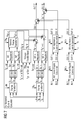
- Figure 7 shows a schematically drawing of a current controller as shown in figure 2 for controlling force ripples of the generator as shown in figure 1 together with two force ripple controllers according to an exemplary embodiment of the invention.
- figure 7 a force ripple control method for controlling force ripples of a generator, the method comprising: performing a method for providing a certain harmonic current reference according to any embodiments of the invention.
- this is achieved by use of two force ripple controllers, one for an Nth force ripple, and another one for an Mth force ripple.
- the method comprises: determining a third output signal OUT3 and a fourth output signal OUT4 depending on the fifth input signal IN5, the first output signal OUT1, the second output signal OUT2 and a set of current signals Ia, Ib, Ic, the set of current signals Ia, Ib, Ic being indicative for a first current Ia, a second current Ib, and a third current Ic each generated by the generator; the third output signal OUT3 being indicative for a harmonic voltage command for the first axle of the synchronous rotating frame; and the fourth output signal OUT4 being indicative for a harmonic voltage command for the second axle of the synchronous rotating frame.
- the method further comprises: determining a seventh output signal OUT7 by adding the third output signal OUT3 to a fifth output signal OUT5, the fifth output signal OUT5 being indicative for a first fundamental voltage command of a current controller of a frequency converter for the generator, and the seventh output signal OUT7 being indicative for a voltage command at the first axle of the synchronous rotating frame, for controlling a radial force ripple of the generator.
- the method further comprises: determining an eighth output signal OUT8 by adding the fourth output signal OUT4 to a sixth output signal OUT6, the sixth output signal OUT6 being indicative for a second fundamental voltage command of the current controller of the frequency converter for the generator, and the eighth output signal OUT8 being indicative for a voltage command at the second axle of the synchronous rotating frame, for controlling a tangential force ripple of the generator.
- figure 7 is shown a diagram of two force ripple controllers, two harmonic current controllers and a generator current controller.
- the fundamental current controller is configured for using fundamental positive-sequence and negative sequence current references, current feedback signals and a generator electrical frequency in combination with fundamental positive and negative sequence regulators Id1+ regulator, Iq1+ regulator, Id1-regulator, Iq1- regulator and a voltage feed-forward providing fundamental voltage commands OUT 5, OUT 6.
- At least one force ripple controller for the force/torque ripples as shown in figure 3 is configured for using the force ripple command (the command is 0 in most of the cases). Measured/estimated force/torque feedback signals and an electrical angle IN5 of the generator in combination with regulators TU1, TU2 for controlling force ripples in order to obtain a harmonic current command OUT 1, OUT 2 are used.
- At least one unit for calculating a harmonic voltage command Out 3, OUT 4 based on the harmonic current command OUT1, OUT2 is used.
- This unit called an Nth/Mth harmonic current controller may provide a closed-loop regulation of a harmonic current or an open-loop calculation of a harmonic voltage.
- Summation elements are configured for adding the voltage commands OUT 2 to OUT 4 and OUT 4 to OUT 6 to achieve the converter control signals OUT 7, OUT 8.
- the same configuration may be used for regulating Mth force ripples as shown in Figure 7 . If more harmonics need to be controlled, more modules may be added. The outputs OUT 3, OUT 4 from different harmonic current controllers shall be then added together.
- the three-phase current was converted to a rotating frame with - we speed by Park transformation.
- the fundamental negative-sequence current is converted from ac to dc after the transformation.
- a PI controller may then be used to regulate the negative current following their references in this rotating frame.
- voltage feed-forward may also be used in this rotating frame. The outputs of voltage feed-forward and positive and negative sequence current regulators are added together providing the fundamental voltage commands OUT 5, OUT 6.
- Figure 7 moreover shows the method comprising: determining a first harmonic voltage command for the first axle of the synchronous rotating frame by applying the electrical angle of the generator, a first current of the generator, a second current of the generator and a third current of the generator to the first harmonic current reference for the first axle of the synchronous rotating frame, such as to receive a first harmonic voltage command for the first axle of the synchronous rotating frame; determining a first harmonic voltage command for the second axle of the synchronous rotating frame by applying the electrical angle of the generator, a first current of the generator, a second current of the generator and a third current of the generator to the first harmonic current reference for the second axle of the synchronous rotating frame, such as to receive a first harmonic voltage command for the second axle of the synchronous rotating frame; adding the first harmonic voltage command for the first axle of the synchronous rotating frame to a fundamental voltage command for the first axle of the synchronous rotating frame, such as to receive a voltage command at the first axle of the synchronous rotating frame, for controlling a radial force ripple of the generator; and adding the
- attachment may comprise bolting, riveting, welding or any other bonding of two materials, depending of the use of the materials and/or parts attached to each other. Where possible and useful, welding, bolting or riveting may be substituted by each other.
- the present invention may aid in reducing acoustic noise and vibration of such a permanent magnet machine, may minimize torque ripples as well as radial force pressure ripples. Moreover, nearly no additional costs may be spent as the invention does allow for only minimal change requirements for hardware of available products already in the market. Moreover, the presented invention allows for very low additional losses due to low amplitude of the harmonic current.
Landscapes
- Engineering & Computer Science (AREA)
- Power Engineering (AREA)
- Control Of Eletrric Generators (AREA)
Priority Applications (1)
| Application Number | Priority Date | Filing Date | Title |
|---|---|---|---|
| EP14188843.8A EP3010143B1 (fr) | 2014-10-14 | 2014-10-14 | Procédé de commande d'ondulation de force d'un générateur |
Applications Claiming Priority (1)
| Application Number | Priority Date | Filing Date | Title |
|---|---|---|---|
| EP14188843.8A EP3010143B1 (fr) | 2014-10-14 | 2014-10-14 | Procédé de commande d'ondulation de force d'un générateur |
Publications (2)
| Publication Number | Publication Date |
|---|---|
| EP3010143A1 true EP3010143A1 (fr) | 2016-04-20 |
| EP3010143B1 EP3010143B1 (fr) | 2017-11-29 |
Family
ID=51690945
Family Applications (1)
| Application Number | Title | Priority Date | Filing Date |
|---|---|---|---|
| EP14188843.8A Active EP3010143B1 (fr) | 2014-10-14 | 2014-10-14 | Procédé de commande d'ondulation de force d'un générateur |
Country Status (1)
| Country | Link |
|---|---|
| EP (1) | EP3010143B1 (fr) |
Cited By (4)
| Publication number | Priority date | Publication date | Assignee | Title |
|---|---|---|---|---|
| WO2020260454A1 (fr) | 2019-06-28 | 2020-12-30 | Wobben Properties Gmbh | Procédé pour réduire au minimum les oscillations d'un générateur |
| WO2021160699A1 (fr) | 2020-02-13 | 2021-08-19 | Wobben Properties Gmbh | Procédé de commande d'un générateur électrique d'une éolienne |
| CN116136206A (zh) * | 2023-03-23 | 2023-05-19 | 中国华能集团清洁能源技术研究院有限公司 | 风电机组的特征振荡频率预警方法及系统 |
| US11949352B2 (en) | 2018-06-22 | 2024-04-02 | Wobben Properties Gmbh | Method for controlling a generator of a wind turbine |
Citations (3)
| Publication number | Priority date | Publication date | Assignee | Title |
|---|---|---|---|---|
| EP2043255A2 (fr) * | 2007-09-28 | 2009-04-01 | General Electric Company | Système et procédé de contrôle d'ondulation de couple dans des machines synchrones |
| EP2485388A1 (fr) * | 2011-02-04 | 2012-08-08 | Siemens Aktiengesellschaft | Réduction du bruit et des vibrations d'un transducteur électromécanique en utilisant un signal modifié d'entraînement de bobine de station comprenant des composantes harmoniques |
| EP2672624A1 (fr) * | 2012-06-05 | 2013-12-11 | Siemens Aktiengesellschaft | Régulateur de courant et système de générateur |
-
2014
- 2014-10-14 EP EP14188843.8A patent/EP3010143B1/fr active Active
Patent Citations (3)
| Publication number | Priority date | Publication date | Assignee | Title |
|---|---|---|---|---|
| EP2043255A2 (fr) * | 2007-09-28 | 2009-04-01 | General Electric Company | Système et procédé de contrôle d'ondulation de couple dans des machines synchrones |
| EP2485388A1 (fr) * | 2011-02-04 | 2012-08-08 | Siemens Aktiengesellschaft | Réduction du bruit et des vibrations d'un transducteur électromécanique en utilisant un signal modifié d'entraînement de bobine de station comprenant des composantes harmoniques |
| EP2672624A1 (fr) * | 2012-06-05 | 2013-12-11 | Siemens Aktiengesellschaft | Régulateur de courant et système de générateur |
Non-Patent Citations (1)
| Title |
|---|
| T.C.Y. WANG ET. AL.: "Design of multiple reference frame PI controller for power converters", IEEE POWER ELECTRONICS SPECIALIST CONFERENCE, 2004, vol. 5, 25 June 2004 (2004-06-25), Aachen, pages 3331 - 3335, XP002737554, ISSN: 0275-9306, ISBN: 0-7803-8399-0, DOI: 10.1109/PESC.2004.1355064 * |
Cited By (6)
| Publication number | Priority date | Publication date | Assignee | Title |
|---|---|---|---|---|
| US11949352B2 (en) | 2018-06-22 | 2024-04-02 | Wobben Properties Gmbh | Method for controlling a generator of a wind turbine |
| WO2020260454A1 (fr) | 2019-06-28 | 2020-12-30 | Wobben Properties Gmbh | Procédé pour réduire au minimum les oscillations d'un générateur |
| DE102019117477A1 (de) * | 2019-06-28 | 2020-12-31 | Wobben Properties Gmbh | Verfahren zum Minimieren von Generatorschwingungen |
| EP3991289B1 (fr) | 2019-06-28 | 2024-11-20 | Wobben Properties GmbH | Procédé pour minimiser les vibrations d'un générateur et unité de contrôle |
| WO2021160699A1 (fr) | 2020-02-13 | 2021-08-19 | Wobben Properties Gmbh | Procédé de commande d'un générateur électrique d'une éolienne |
| CN116136206A (zh) * | 2023-03-23 | 2023-05-19 | 中国华能集团清洁能源技术研究院有限公司 | 风电机组的特征振荡频率预警方法及系统 |
Also Published As
| Publication number | Publication date |
|---|---|
| EP3010143B1 (fr) | 2017-11-29 |
Similar Documents
| Publication | Publication Date | Title |
|---|---|---|
| EP3605812B1 (fr) | Système de génération d'énergie cc comportant une compensation des ondulations de tension | |
| US10848087B2 (en) | Control arrangment for a generator | |
| EP2672624B1 (fr) | Régulateur de courant et système de générateur | |
| US7336509B2 (en) | Method and apparatus for estimating line inductance for PWM rectifier control | |
| EP2485388B1 (fr) | Réduction du bruit et des vibrations d'un transducteur électromécanique en utilisant un signal modifié d'entraînement de bobine de station comprenant des composantes harmoniques | |
| EP3264593B1 (fr) | Agencement de commande pour un générateur | |
| EP2865889B1 (fr) | Amortissement d'oscillations de train d'entraînement de turbine éolienne | |
| KR102095978B1 (ko) | 기어리스 풍력 터빈의 동기식 발전기를 제어하는 방법 | |
| Houari et al. | An effective compensation technique for speed smoothness at low-speed operation of PMSM drives | |
| EP3480931B1 (fr) | Regulation d'harmoniques d'un convertisseur | |
| JP6079094B2 (ja) | インバータ制御装置 | |
| EP2750270A1 (fr) | Contrôleur de courant harmonique | |
| EP2552012A1 (fr) | Réduction du bruit et des vibrations d'un transducteur électromécanique en utilisant un signal modifié d'entraînement de bobine de station comprenant des composantes harmoniques | |
| EP3010143B1 (fr) | Procédé de commande d'ondulation de force d'un générateur | |
| EP2869458A1 (fr) | Régulateur de courant d'une éolienne | |
| EP3258594B1 (fr) | Commande d'une machine électrique à réglage multiple | |
| EP3935727B1 (fr) | Contrôle de couple harmonique direct d'une machine électrique | |
| CN108809177A (zh) | 无电解电容电机驱动方法、装置、电子设备及存储介质 | |
| CN105576694B (zh) | 控制来自具有不平衡阻抗的发电机的能量流 | |
| Iacchetti et al. | Enhanced torque control in a DFIG connected to a DC grid by a diode rectifier | |
| CN111564997B (zh) | 转换器的谐波控制 | |
| RU2709098C1 (ru) | Устройство согласованного управления электроприводами с электронной редукцией | |
| Rao et al. | Comparison of the Performmance of DTC of Induction Gen Nerator in Wind Energy Conversion System with PI and Neurral Controllers | |
| CN120320648A (zh) | 基于自适应前馈电压补偿的三维弱磁控制方法和系统 |
Legal Events
| Date | Code | Title | Description |
|---|---|---|---|
| PUAI | Public reference made under article 153(3) epc to a published international application that has entered the european phase |
Free format text: ORIGINAL CODE: 0009012 |
|
| AK | Designated contracting states |
Kind code of ref document: A1 Designated state(s): AL AT BE BG CH CY CZ DE DK EE ES FI FR GB GR HR HU IE IS IT LI LT LU LV MC MK MT NL NO PL PT RO RS SE SI SK SM TR |
|
| AX | Request for extension of the european patent |
Extension state: BA ME |
|
| 17P | Request for examination filed |
Effective date: 20160920 |
|
| RBV | Designated contracting states (corrected) |
Designated state(s): AL AT BE BG CH CY CZ DE DK EE ES FI FR GB GR HR HU IE IS IT LI LT LU LV MC MK MT NL NO PL PT RO RS SE SI SK SM TR |
|
| GRAP | Despatch of communication of intention to grant a patent |
Free format text: ORIGINAL CODE: EPIDOSNIGR1 |
|
| INTG | Intention to grant announced |
Effective date: 20170628 |
|
| RAP1 | Party data changed (applicant data changed or rights of an application transferred) |
Owner name: SIEMENS AKTIENGESELLSCHAFT |
|
| GRAS | Grant fee paid |
Free format text: ORIGINAL CODE: EPIDOSNIGR3 |
|
| GRAA | (expected) grant |
Free format text: ORIGINAL CODE: 0009210 |
|
| AK | Designated contracting states |
Kind code of ref document: B1 Designated state(s): AL AT BE BG CH CY CZ DE DK EE ES FI FR GB GR HR HU IE IS IT LI LT LU LV MC MK MT NL NO PL PT RO RS SE SI SK SM TR |
|
| REG | Reference to a national code |
Ref country code: CH Ref legal event code: EP |
|
| REG | Reference to a national code |
Ref country code: AT Ref legal event code: REF Ref document number: 951262 Country of ref document: AT Kind code of ref document: T Effective date: 20171215 |
|
| REG | Reference to a national code |
Ref country code: IE Ref legal event code: FG4D |
|
| REG | Reference to a national code |
Ref country code: DE Ref legal event code: R096 Ref document number: 602014017823 Country of ref document: DE |
|
| REG | Reference to a national code |
Ref country code: NL Ref legal event code: MP Effective date: 20171129 |
|
| REG | Reference to a national code |
Ref country code: LT Ref legal event code: MG4D |
|
| REG | Reference to a national code |
Ref country code: AT Ref legal event code: MK05 Ref document number: 951262 Country of ref document: AT Kind code of ref document: T Effective date: 20171129 |
|
| PG25 | Lapsed in a contracting state [announced via postgrant information from national office to epo] |
Ref country code: FI Free format text: LAPSE BECAUSE OF FAILURE TO SUBMIT A TRANSLATION OF THE DESCRIPTION OR TO PAY THE FEE WITHIN THE PRESCRIBED TIME-LIMIT Effective date: 20171129 Ref country code: LT Free format text: LAPSE BECAUSE OF FAILURE TO SUBMIT A TRANSLATION OF THE DESCRIPTION OR TO PAY THE FEE WITHIN THE PRESCRIBED TIME-LIMIT Effective date: 20171129 Ref country code: ES Free format text: LAPSE BECAUSE OF FAILURE TO SUBMIT A TRANSLATION OF THE DESCRIPTION OR TO PAY THE FEE WITHIN THE PRESCRIBED TIME-LIMIT Effective date: 20171129 Ref country code: SE Free format text: LAPSE BECAUSE OF FAILURE TO SUBMIT A TRANSLATION OF THE DESCRIPTION OR TO PAY THE FEE WITHIN THE PRESCRIBED TIME-LIMIT Effective date: 20171129 Ref country code: NO Free format text: LAPSE BECAUSE OF FAILURE TO SUBMIT A TRANSLATION OF THE DESCRIPTION OR TO PAY THE FEE WITHIN THE PRESCRIBED TIME-LIMIT Effective date: 20180228 |
|
| PG25 | Lapsed in a contracting state [announced via postgrant information from national office to epo] |
Ref country code: RS Free format text: LAPSE BECAUSE OF FAILURE TO SUBMIT A TRANSLATION OF THE DESCRIPTION OR TO PAY THE FEE WITHIN THE PRESCRIBED TIME-LIMIT Effective date: 20171129 Ref country code: GR Free format text: LAPSE BECAUSE OF FAILURE TO SUBMIT A TRANSLATION OF THE DESCRIPTION OR TO PAY THE FEE WITHIN THE PRESCRIBED TIME-LIMIT Effective date: 20180301 Ref country code: HR Free format text: LAPSE BECAUSE OF FAILURE TO SUBMIT A TRANSLATION OF THE DESCRIPTION OR TO PAY THE FEE WITHIN THE PRESCRIBED TIME-LIMIT Effective date: 20171129 Ref country code: BG Free format text: LAPSE BECAUSE OF FAILURE TO SUBMIT A TRANSLATION OF THE DESCRIPTION OR TO PAY THE FEE WITHIN THE PRESCRIBED TIME-LIMIT Effective date: 20180228 Ref country code: AT Free format text: LAPSE BECAUSE OF FAILURE TO SUBMIT A TRANSLATION OF THE DESCRIPTION OR TO PAY THE FEE WITHIN THE PRESCRIBED TIME-LIMIT Effective date: 20171129 Ref country code: LV Free format text: LAPSE BECAUSE OF FAILURE TO SUBMIT A TRANSLATION OF THE DESCRIPTION OR TO PAY THE FEE WITHIN THE PRESCRIBED TIME-LIMIT Effective date: 20171129 |
|
| PG25 | Lapsed in a contracting state [announced via postgrant information from national office to epo] |
Ref country code: NL Free format text: LAPSE BECAUSE OF FAILURE TO SUBMIT A TRANSLATION OF THE DESCRIPTION OR TO PAY THE FEE WITHIN THE PRESCRIBED TIME-LIMIT Effective date: 20171129 |
|
| PG25 | Lapsed in a contracting state [announced via postgrant information from national office to epo] |
Ref country code: SK Free format text: LAPSE BECAUSE OF FAILURE TO SUBMIT A TRANSLATION OF THE DESCRIPTION OR TO PAY THE FEE WITHIN THE PRESCRIBED TIME-LIMIT Effective date: 20171129 Ref country code: CZ Free format text: LAPSE BECAUSE OF FAILURE TO SUBMIT A TRANSLATION OF THE DESCRIPTION OR TO PAY THE FEE WITHIN THE PRESCRIBED TIME-LIMIT Effective date: 20171129 Ref country code: CY Free format text: LAPSE BECAUSE OF FAILURE TO SUBMIT A TRANSLATION OF THE DESCRIPTION OR TO PAY THE FEE WITHIN THE PRESCRIBED TIME-LIMIT Effective date: 20171129 Ref country code: DK Free format text: LAPSE BECAUSE OF FAILURE TO SUBMIT A TRANSLATION OF THE DESCRIPTION OR TO PAY THE FEE WITHIN THE PRESCRIBED TIME-LIMIT Effective date: 20171129 Ref country code: EE Free format text: LAPSE BECAUSE OF FAILURE TO SUBMIT A TRANSLATION OF THE DESCRIPTION OR TO PAY THE FEE WITHIN THE PRESCRIBED TIME-LIMIT Effective date: 20171129 |
|
| REG | Reference to a national code |
Ref country code: DE Ref legal event code: R097 Ref document number: 602014017823 Country of ref document: DE |
|
| PG25 | Lapsed in a contracting state [announced via postgrant information from national office to epo] |
Ref country code: SM Free format text: LAPSE BECAUSE OF FAILURE TO SUBMIT A TRANSLATION OF THE DESCRIPTION OR TO PAY THE FEE WITHIN THE PRESCRIBED TIME-LIMIT Effective date: 20171129 Ref country code: PL Free format text: LAPSE BECAUSE OF FAILURE TO SUBMIT A TRANSLATION OF THE DESCRIPTION OR TO PAY THE FEE WITHIN THE PRESCRIBED TIME-LIMIT Effective date: 20171129 Ref country code: RO Free format text: LAPSE BECAUSE OF FAILURE TO SUBMIT A TRANSLATION OF THE DESCRIPTION OR TO PAY THE FEE WITHIN THE PRESCRIBED TIME-LIMIT Effective date: 20171129 Ref country code: IT Free format text: LAPSE BECAUSE OF FAILURE TO SUBMIT A TRANSLATION OF THE DESCRIPTION OR TO PAY THE FEE WITHIN THE PRESCRIBED TIME-LIMIT Effective date: 20171129 |
|
| PLBE | No opposition filed within time limit |
Free format text: ORIGINAL CODE: 0009261 |
|
| STAA | Information on the status of an ep patent application or granted ep patent |
Free format text: STATUS: NO OPPOSITION FILED WITHIN TIME LIMIT |
|
| 26N | No opposition filed |
Effective date: 20180830 |
|
| PG25 | Lapsed in a contracting state [announced via postgrant information from national office to epo] |
Ref country code: SI Free format text: LAPSE BECAUSE OF FAILURE TO SUBMIT A TRANSLATION OF THE DESCRIPTION OR TO PAY THE FEE WITHIN THE PRESCRIBED TIME-LIMIT Effective date: 20171129 |
|
| REG | Reference to a national code |
Ref country code: CH Ref legal event code: PL |
|
| REG | Reference to a national code |
Ref country code: BE Ref legal event code: MM Effective date: 20181031 |
|
| PG25 | Lapsed in a contracting state [announced via postgrant information from national office to epo] |
Ref country code: MC Free format text: LAPSE BECAUSE OF FAILURE TO SUBMIT A TRANSLATION OF THE DESCRIPTION OR TO PAY THE FEE WITHIN THE PRESCRIBED TIME-LIMIT Effective date: 20171129 Ref country code: LU Free format text: LAPSE BECAUSE OF NON-PAYMENT OF DUE FEES Effective date: 20181014 |
|
| REG | Reference to a national code |
Ref country code: DE Ref legal event code: R081 Ref document number: 602014017823 Country of ref document: DE Owner name: SIEMENS GAMESA RENEWABLE ENERGY A/S, DK Free format text: FORMER OWNER: SIEMENS AKTIENGESELLSCHAFT, 80333 MUENCHEN, DE |
|
| REG | Reference to a national code |
Ref country code: IE Ref legal event code: MM4A |
|
| PG25 | Lapsed in a contracting state [announced via postgrant information from national office to epo] |
Ref country code: BE Free format text: LAPSE BECAUSE OF NON-PAYMENT OF DUE FEES Effective date: 20181031 Ref country code: CH Free format text: LAPSE BECAUSE OF NON-PAYMENT OF DUE FEES Effective date: 20181031 Ref country code: LI Free format text: LAPSE BECAUSE OF NON-PAYMENT OF DUE FEES Effective date: 20181031 Ref country code: FR Free format text: LAPSE BECAUSE OF NON-PAYMENT OF DUE FEES Effective date: 20181031 |
|
| PG25 | Lapsed in a contracting state [announced via postgrant information from national office to epo] |
Ref country code: IE Free format text: LAPSE BECAUSE OF NON-PAYMENT OF DUE FEES Effective date: 20181014 |
|
| REG | Reference to a national code |
Ref country code: GB Ref legal event code: 732E Free format text: REGISTERED BETWEEN 20191128 AND 20191204 |
|
| PG25 | Lapsed in a contracting state [announced via postgrant information from national office to epo] |
Ref country code: MT Free format text: LAPSE BECAUSE OF NON-PAYMENT OF DUE FEES Effective date: 20181014 |
|
| PG25 | Lapsed in a contracting state [announced via postgrant information from national office to epo] |
Ref country code: TR Free format text: LAPSE BECAUSE OF FAILURE TO SUBMIT A TRANSLATION OF THE DESCRIPTION OR TO PAY THE FEE WITHIN THE PRESCRIBED TIME-LIMIT Effective date: 20171129 |
|
| PG25 | Lapsed in a contracting state [announced via postgrant information from national office to epo] |
Ref country code: PT Free format text: LAPSE BECAUSE OF FAILURE TO SUBMIT A TRANSLATION OF THE DESCRIPTION OR TO PAY THE FEE WITHIN THE PRESCRIBED TIME-LIMIT Effective date: 20171129 |
|
| PG25 | Lapsed in a contracting state [announced via postgrant information from national office to epo] |
Ref country code: MK Free format text: LAPSE BECAUSE OF NON-PAYMENT OF DUE FEES Effective date: 20171129 Ref country code: HU Free format text: LAPSE BECAUSE OF FAILURE TO SUBMIT A TRANSLATION OF THE DESCRIPTION OR TO PAY THE FEE WITHIN THE PRESCRIBED TIME-LIMIT; INVALID AB INITIO Effective date: 20141014 |
|
| PG25 | Lapsed in a contracting state [announced via postgrant information from national office to epo] |
Ref country code: AL Free format text: LAPSE BECAUSE OF FAILURE TO SUBMIT A TRANSLATION OF THE DESCRIPTION OR TO PAY THE FEE WITHIN THE PRESCRIBED TIME-LIMIT Effective date: 20171129 Ref country code: IS Free format text: LAPSE BECAUSE OF FAILURE TO SUBMIT A TRANSLATION OF THE DESCRIPTION OR TO PAY THE FEE WITHIN THE PRESCRIBED TIME-LIMIT Effective date: 20180329 |
|
| PGFP | Annual fee paid to national office [announced via postgrant information from national office to epo] |
Ref country code: GB Payment date: 20250901 Year of fee payment: 12 |
|
| PGFP | Annual fee paid to national office [announced via postgrant information from national office to epo] |
Ref country code: DE Payment date: 20250731 Year of fee payment: 12 |