EP3010166A1 - Appareil, récepteur optique, procédé et programme informatique pour le traitement d'un premier et un deuxième signal électrique en fonction d'un signal multiplexé en polarisation comprenant deux polarisations - Google Patents
Appareil, récepteur optique, procédé et programme informatique pour le traitement d'un premier et un deuxième signal électrique en fonction d'un signal multiplexé en polarisation comprenant deux polarisations Download PDFInfo
- Publication number
- EP3010166A1 EP3010166A1 EP14306613.2A EP14306613A EP3010166A1 EP 3010166 A1 EP3010166 A1 EP 3010166A1 EP 14306613 A EP14306613 A EP 14306613A EP 3010166 A1 EP3010166 A1 EP 3010166A1
- Authority
- EP
- European Patent Office
- Prior art keywords
- signal
- polarization
- equalized
- electrical
- module
- Prior art date
- Legal status (The legal status is an assumption and is not a legal conclusion. Google has not performed a legal analysis and makes no representation as to the accuracy of the status listed.)
- Withdrawn
Links
- 230000010287 polarization Effects 0.000 title claims abstract description 143
- 230000003287 optical effect Effects 0.000 title claims abstract description 42
- 238000000034 method Methods 0.000 title claims abstract description 32
- 238000012545 processing Methods 0.000 title claims abstract description 24
- 238000004590 computer program Methods 0.000 title claims abstract description 13
- 230000003044 adaptive effect Effects 0.000 claims description 10
- 230000010363 phase shift Effects 0.000 claims description 10
- 238000001914 filtration Methods 0.000 claims description 5
- 230000003111 delayed effect Effects 0.000 claims description 3
- 238000010586 diagram Methods 0.000 description 26
- 230000006870 function Effects 0.000 description 12
- 230000005540 biological transmission Effects 0.000 description 8
- 238000004891 communication Methods 0.000 description 7
- 238000005259 measurement Methods 0.000 description 6
- 230000001419 dependent effect Effects 0.000 description 4
- 238000006243 chemical reaction Methods 0.000 description 3
- 239000006185 dispersion Substances 0.000 description 3
- 230000009467 reduction Effects 0.000 description 3
- 230000004044 response Effects 0.000 description 3
- 230000006978 adaptation Effects 0.000 description 2
- 238000003491 array Methods 0.000 description 2
- 238000013500 data storage Methods 0.000 description 2
- 230000009977 dual effect Effects 0.000 description 2
- 230000000694 effects Effects 0.000 description 2
- 230000015654 memory Effects 0.000 description 2
- 238000012986 modification Methods 0.000 description 2
- 230000004048 modification Effects 0.000 description 2
- 230000008569 process Effects 0.000 description 2
- 238000012360 testing method Methods 0.000 description 2
- 229920000954 Polyglycolide Polymers 0.000 description 1
- 238000010276 construction Methods 0.000 description 1
- 230000001934 delay Effects 0.000 description 1
- 239000000835 fiber Substances 0.000 description 1
- 230000003993 interaction Effects 0.000 description 1
- 229920000747 poly(lactic acid) Polymers 0.000 description 1
- 235000010409 propane-1,2-diol alginate Nutrition 0.000 description 1
- 238000000926 separation method Methods 0.000 description 1
- 230000003068 static effect Effects 0.000 description 1
- 230000007704 transition Effects 0.000 description 1
Images






Classifications
-
- H—ELECTRICITY
- H04—ELECTRIC COMMUNICATION TECHNIQUE
- H04B—TRANSMISSION
- H04B10/00—Transmission systems employing electromagnetic waves other than radio-waves, e.g. infrared, visible or ultraviolet light, or employing corpuscular radiation, e.g. quantum communication
- H04B10/60—Receivers
- H04B10/61—Coherent receivers
- H04B10/614—Coherent receivers comprising one or more polarization beam splitters, e.g. polarization multiplexed [PolMux] X-PSK coherent receivers, polarization diversity heterodyne coherent receivers
-
- H—ELECTRICITY
- H04—ELECTRIC COMMUNICATION TECHNIQUE
- H04B—TRANSMISSION
- H04B10/00—Transmission systems employing electromagnetic waves other than radio-waves, e.g. infrared, visible or ultraviolet light, or employing corpuscular radiation, e.g. quantum communication
- H04B10/60—Receivers
- H04B10/61—Coherent receivers
- H04B10/616—Details of the electronic signal processing in coherent optical receivers
- H04B10/6166—Polarisation demultiplexing, tracking or alignment of orthogonal polarisation components
Definitions
- Embodiments relate to an apparatus, an optical receiver, a method and a computer program for processing a first and a second electrical signal based on a polarization multiplexed signal comprising two polarizations, more particularly but not exclusively to filtering and demultiplexing of different polarizations from a polarization multiplexed signal.
- a wireless communication network may comprise a Radio Access Network (RAN) part, which establishes and controls wireless access, and a Core Network (CN), through which other networks and other users of the wireless communication network are connected.
- RAN Radio Access Network
- CN Core Network
- RAN Radio Access Network
- CN Core Network
- Another example of a packet data or a packet switched communication network is the communication network established between the servers and routers of the World Wide Web (WWW).
- WWW World Wide Web
- digital data values may be transmitted by means of an optical transmission signal.
- the optical transmission signal is generated by modulating the phase and/or the amplitude of an optical carrier signal, which possesses a carrier frequency, in dependence on the transmitted data values and in accordance with a constellation diagram of a respective Phase-Shift Keying (PSK) modulation or Quadrature Amplitude Modulation (QAM) method.
- PSK Phase-Shift Keying
- QAM Quadrature Amplitude Modulation
- Prominent examples are Binary Phase Shift Keying (BPSK), Quaternary Phase Shift Keying (QPSK), 16 QAM, 64 QAM, etc.
- both the electrical and magnetic polarizations of a signal can be used (polarization multiplexing).
- the two signal components can be used separately, or they can be used in combination, allowing the construction of more complex and efficient codes, but also requiring a synchronization of the signals on the two polarizations.
- Various embodiments provide an apparatus, an optical receiver, a method and a computer program for processing a first and a second electrical signal, wherein the first and second electrical signals are based on a polarization multiplexed signal comprising two polarizations.
- existing optical cables can often be retrofitted with new optical transmitters and receivers, operators of such cables are often looking to find a way to increase the bandwidth on such cables, so no new cables are necessary when the demand for a higher bandwidth arises.
- One method of increasing the bandwidth of existing cables is the separate use of two polarizations of an optical signal (polarization multiplexing). To further increase the information transmitted in each clock cycle, the two polarizations may be used in combination to build more complex symbols and allow the transmission of more information per clock cycle.
- Embodiments provide an apparatus for processing a first electrical signal and a second electrical signal.
- the first and second electrical signals are based on a polarization multiplexed signal.
- the apparatus comprises a filter module to equalize the first electrical signal resulting in a first equalized signal, and to equalize the second electrical signal resulting in a second equalized signal.
- the apparatus further comprises a de-multiplexing module to determine a first de-multiplexed signal and a second de-multiplexed signal based on the first equalized signal and the second equalized signal.
- the first de-multiplexed signal basically comprises components of the polarization multiplexed signal of one polarization
- the second de-multiplexed signal basically comprises components of the polarization multiplexed signal of the other polarization, potentially making it possible to use a combined signal consisting of both polarizations.
- the filter module may comprise four filters which are configurable by filter coefficients. Two filters may be used to determine the first equalized signal from the first electrical signal and the second electrical signal, and the two other filters may be used to determine the second equalized signal from the second electrical signal and the first electrical signal.
- the coefficients of the filters may be based on a superposition of former first and second equalized signals, providing both equalization of the first and second electrical signal and polarization alignment of the first and second electrical signal, possibly using information of both signals to adjust the coefficients of the filters based on signal components of both polarizations.
- the filter module may comprise two filters. One filter may be used to determine the first equalized signal from the first electrical signal, and the other filter may be used to determine the second equalized signal from the second electrical signal.
- the coefficients of the filters may be based on former first and second equalized signals. Due to only using two filter modules, less hardware resources may be required for implementation.
- a modulation used for the polarization multiplexed signal may be based on combinations of both polarizations, possibly increasing the information that can be transmitted simultaneously, or it may use two modulations independently for the two polarizations.
- the de-multiplexing module may comprise at least one polarization control module.
- the polarization control module may comprise a first computation module to determine the first de-multiplexed signal based on a weighted combination of the first equalized signal and the second equalized signal, and a second computation module to determine the second de-multiplexed signal based on a weighted combination of the first equalized signal and the second equalized signal. De-multiplexing the first and second equalized signal may hence be based on combinations of the equalized signals from both polarizations.
- At least one of the first computation module or the second computation module may be configured to apply a phase shift to the first or second equalized signal before determining the first or second de-multiplexed signal.
- Embodiments may counter the effects of polarization mode dispersion (PMD) and similar effects.
- the first computation module may be configured to determine the first de-multiplexed signal based on the first equalized signal, the cosine of a variable ⁇ , the second equalized signal, and the sine of ⁇ .
- the second computation module may be configured to determine the second de-multiplexed signal based on the first equalized signal, the negative sine of ⁇ , a phase-shifted version of the second equalized signal, and the cosine of ⁇ .
- the first and second de-multiplexed signals may then contain separated signals from the two polarizations.
- the de-multiplexing module may comprise two or more polarization control modules, which may be configured to operate subsequently to obtain the first and second de-multiplexed signal. At least one intermediate output of a polarization control module may be delayed before subsequent processing. Embodiments may allow compensating for higher order PMD.
- the apparatus may further comprise a control module to provide configuration information to the filter module and/or the de-multiplexing module.
- Embodiments may implement adaptive algorithms to adjust equalization and polarization alignment.
- control module may be configured to provide the filter module with information related to filter coefficients based on a former first equalized signal and a former second equalized signal.
- Embodiments may provide transmission channel adaptive equalization.
- control module may also be configured to provide the demultiplexing module with information related to a phase shift configuration and/or information related to a rotation configuration.
- the information may be based on former first and second de-multiplexed signals and/or based on former intermediate outputs of the demultiplexing module. Said information may then be used to perform polarization alignment and de-multiplexing.
- the control module may, in some embodiments, also be configured to carry out adaptive filtering on the first and second electrical signals together with the filter module.
- the control module may further be configured to carry out adaptive polarization de-multiplexing of the first and second equalized signals together with the de-multiplexing module.
- the control module may provide coefficients for both the filter and the demultiplexing module.
- Embodiments also provide an optical receiver comprising the apparatus, and further comprising one or more optical/electrical converters having optical inputs and electrical outputs.
- the first and second electrical signal may then be based on the electrical outputs of the one or more optical/electrical converters.
- Embodiments may provide an improved optical receiver.
- Embodiments further provide a method for processing a first electrical signal and a second electrical signal.
- the first and second electrical signals are based on a polarization multiplexed signal.
- the method comprises equalizing the first electrical signal resulting in a first equalized signal, equalizing the second electrical signal resulting in a second equalized signal, and determining a first de-multiplexed signal based on the first equalized signal and the second equalized signals.
- the first de-multiplexed signal basically comprises components of the polarization multiplexed signal of one polarization.
- the method further comprises determining a second de-multiplexed signal based on the first equalized signal and the second equalized signals.
- the second de-multiplexed signal basically comprises components of the polarization multiplexed signal of the other polarization.
- Embodiments further provide a computer program having a program code for performing at the above method, when the computer program is executed on a computer, a processor, or a programmable hardware component.
- a further embodiment is a computer readable storage medium storing instructions which, when executed by a computer, processor, or programmable hardware component, cause the computer to implement one of the methods described herein.
- the term, "or” refers to a non-exclusive or, unless otherwise indicated (e.g., “or else” or “or in the alternative”).
- words used to describe a relationship between elements should be broadly construed to include a direct relationship or the presence of intervening elements unless otherwise indicated. For example, when an element is referred to as being “connected” or “coupled” to another element, the element may be directly connected or coupled to the other element or intervening elements may be present. In contrast, when an element is referred to as being “directly connected” or “directly coupled” to another element, there are no intervening elements present. Similarly, words such as “between”, “adjacent”, and the like should be interpreted in a like fashion.
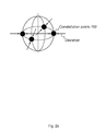
- two categories of modulations may be used: two 2D modulations ( Fig. 2a ), which each use a single polarization, or one 4D modulation, which may synchronously use both polarization ( Fig. 2b ).
- Fig. 2a shows two 2D QPSK modulations with constellation points 700a for the horizontal polarization, and constellation points 700b for the vertical polarization.
- a 4D modulation such as polarization switched QPSK (PS-QPSK) as seen in Fig. 2b , may use constellation points 702 based on both polarizations.
- PS-QPSK polarization switched QPSK
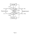
- the polarization demultiplexing stage may typically be combined with an alignment of the electrical phase and the channel equalization, as seen in Fig. 2c , using, for instance, four finite impulse response filters 612a-d with filter coefficient adaptation based only based on the respective polarization.
- Embodiments may enable channel equalization and polarization de-multiplexing for 4D modulation formats like polarization switched QPSK, polarization QAM and others. Some embodiments may consider a decision prior to a Constant Modulo Algorithm (CMA), which may cause a loss in performance. Some embodiments may delay 2 polarizations leading to independent 2D signals. However, some embodiments may provide higher performance and adapt to more complex 4D signals.
- CMA Constant Modulo Algorithm
- polarization demultiplexing In case of fast polarization variations or fast variations of the Polarization Mode Dispersion (PMD) a number of tasks of a filter might be performed with high accuracy: polarization demultiplexing, re-timing, and channel equalization. The latter two might be considered as rather slow processes. For high accuracy long filters may be used to realize a high number of filter coefficients. In general, long filters may be slower than shorter filters. So, when it comes to filter length performance comparison there might be either a loss of performance or a reduction of maximum speed to be taken into account. As another criterion implementation complexity may be considered in some embodiments. From a complexity point of view the CMA may be border lining. A reduction of complexity may reduce chip space of Digital Signal Processors (DSPs) and power consumption.
- DSPs Digital Signal Processors
- the basic idea of at least some embodiments is the implementation of a true 4D CMA.
- the polarization de-multiplexing may be separated from the channel equalization and retiming. This separation may be introduced by a 4D feedback signal, which may be considered blind against polarization rotation.
- the polarization de-multiplexing may be implemented in a separate block using a simple polarization controller. Such polarization controllers may correspond to a very simple block. If polarization alignment is not considered mandatory to be implemented within the CMA, the cross paths of the CMA may be deleted leading to a strong reduction in implementation effort.
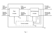
- FIG. 1 illustrates a block diagram of an embodiment of an apparatus 10, comprising a filter module 12, a de-multiplexing module 14, and an optional control module 16. As shown in Fig. 1 the filter module 12 is coupled to the de-multiplexing module 14, and both may be coupled to the optional control module 16.
- the apparatus 10 is operable for processing a first electrical signal and a second electrical signal, wherein the first and second electrical signals are based on a polarization multiplexed signal.
- the polarization multiplexed signal may correspond to a polarization multiplexed optical signal
- the first and second electrical signals may correspond to polarization filtered optical signals, where different polarization directions are used for the first and second electrical signals.
- each of the first and second electrical signals may comprise polarization components of an originally transmitted signal.
- the apparatus 10 comprises a filter module 12 to equalize the first electrical signal resulting in a first equalized signal, and to equalize the second electrical signal resulting in a second equalized signal. It further comprises a de-multiplexing module 14 to determine a first de-multiplexed signal and a second de-multiplexed signal based on the first equalized signal and the second equalized signal, wherein the first de-multiplexed signal basically comprises components of the polarization multiplexed signal of one polarization, and wherein the second de-multiplexed signal basically comprises components of the polarization multiplexed signal of the other polarization.
- the polarization components of an originally transmitted signal may be basically reconstructed in the first and second de-multiplexed signals.
- the filter module 12, the de-multiplexing module 14, and/or a control module 16 may be implemented using one or more processing units, one or more processing devices, any means for processing, such as a processor, a computer or a programmable hardware component being operable with accordingly adapted software, a DSP, etc.
- any means for processing such as a processor, a computer or a programmable hardware component being operable with accordingly adapted software, a DSP, etc.
- the described functions of the modules 12, 14, and/or 16 may as well be implemented in software, which is then executed on one or more programmable hardware components.
- Such hardware components may comprise a general purpose processor, a DSP, a micro-controller, etc.
- a modulation used for the polarization multiplexed signal may be based on combinations of both polarizations, such as, for instance, polarized QAM or polarization switched QPSK, or two modulations may be used independently for the two polarizations.
- a CMA for 4 dimensional signals is introduced with a feedback unit, for example implemented as the control module 16, calculating the deviation of a 4D symbol based on a symbol alphabet from the 4D estimation based on the de-multiplexed first and second signals.
- a CMA without the opportunity for polarization alignment meaning without any cross filters may be utilized and the application of a higher order PMD canceler prior or after the CMA, as will be detailed subsequently.
- the apparatus 10 may further comprise the control module 16, as indicated by the dashed lines in Fig. 1 , to provide configuration information to the filter module 12 and/or the de-multiplexing module 14.
- control module 16 may be configured to provide the filter module 12 with information related to filter coefficients based on a former first equalized signal and a former second equalized signal.
- the provision of former signals shall indicate a time discrete feedback loop used to feedback information based on an output processed in a former time interval.
- control module 16 may also be configured to provide the de-multiplexing module 14 with information related to a phase shift configuration and/or information related to a rotation configuration based on former first and second de-multiplexed signals and/or based on former intermediate outputs of the de-multiplexing module.
- control module 16 may be configured to carry out adaptive filtering on the first and second electrical signals together with the filter module 12.
- the control module 16 may be further configured to carry out adaptive polarization demultiplexing of the first and second equalized signals together with the de-multiplexing module 14, as will be detailed subsequently.
- the information related to filter coefficients may be based on information provided by a Constant Modulus Algorithm (CMA) based on a minimization of an error cost function.
- CMA Constant Modulus Algorithm
- the filter module 12 may comprise four filters 12a-d which are configurable by filter coefficients.
- Two filters 12a, 12b may be used to determine the first equalized signal from the first electrical signal and the second electrical signal.
- the two other filters 12c, 12d may be used to determine the second equalized signal from the second electrical signal and the first electrical signal.
- the coefficients of the filters 12a-d may, as shown in Fig. 4 , be based on a superposition or combination of former first and second equalized signals, providing equalization of the first and second electrical signal and, additionally or alternatively, polarization alignment of the first and second electrical signal.
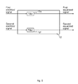
- Fig. 5 illustrates a block diagram of an embodiment of the filter module 12 comprising two filters 12e, 12f.
- cross filters 12b, 12c as depicted in Fig. 3 have been deleted.
- One filter 12e may be used to determine the first equalized signal from the first electrical signal.
- the other filter 12f may be used to determine the second equalized signal from the second electrical signal.
- the coefficients of the filters 12e and/or 12f may be based on former first and second equalized signals, as further detailed in Fig. 6.
- Fig. 6 shows an adaptive filter module 12, with two filters 12e and 12f, to provide the first and second equalized signals.
- the filters comprised in the filter module 12 may correspond to finite impulse response (FIR) filters, infinite impulse response (IIR) filters, or other filters known in the art.
- FIR finite impulse response
- IIR infinite impulse response
- Fig. 7 illustrates a block diagram of an embodiment of the de-multiplexing module 14 comprising at least one polarization control module 14a.
- the at least one polarization control module 14a may comprise a first computation module 14b to determine the first de-multiplexed signal based on a weighted combination of the first equalized signal and the second equalized signal. It may further comprise a second computation module 14c to determine the second de-multiplexed signal based on a weighted combination of the first equalized signal and the second equalized signal.
- At least one of the first computation module 14b or the second computation module 14c may be configured to apply a phase shift 14d to the first or second equalized signal before determining the first or second de-multiplexed signal.
- the first computation module 14b may be configured to determine the first de-multiplexed signal based on the first equalized signal, the cosine of a variable ⁇ , the second equalized signal, and the sine of ⁇ , respectively.
- the second computation module 14c may be configured to determine the second de-multiplexed signal based on the first equalized signal, the negative sine of ⁇ , a phase-shifted version of the second equalized signal, and the cosine of ⁇ .
- ⁇ may correspond to an angular deviation of the polarization directions represented by the first and second equalized signals (one of which may be phase shifted) and the polarization direction of the optical receive signal at optical polarization filtering/de-multiplexing.
- the filter module 12 might provide polarization alignment, in some embodiments it might not.
- polarization alignment may be provided by the polarization control module 14a of the de-multiplexing module 14.
- higher order PMD may be compensated by one or more additional polarization controllers.
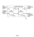
- concatenated delay lines may be applied with fixed or variable polarization controllers in-between, as shown in Fig. 9.
- Fig. 9 shows an embodiment of the de-multiplexing module 14, with two subsequent polarization controllers 14a1 and 14a2, where in the upper path delay components delay the signals before further processing.
- the higher order compensator can be located prior or after the CMA.
- the delays may be half a symbol period (delay by one sample), one sample (delay by 2 samples) or intermediate steps using an interpolation filter. In some embodiments the latter may be implemented as a static filter without any adaptation.
- Fig. 9 shows a block diagram of an embodiment of the de-multiplexing module 14 comprising two or more polarization control modules 14a1 and 14a2, which are configured to operate subsequently to obtain the first and second de-multiplexed signal.
- at least one intermediate output of a polarization control module may be delayed before subsequent processing.
- Fig. 10 and 11 show waterfall diagrams of test results using a 2D CMA ( Fig. 10 ) and using an embodiment of apparatus 10 ( Fig. 11 ).
- the x-axis denotes the bit error rate (BER)
- the y-axis denotes the optical signal-to-noise ratio in dB.
- Fig. 10 comprises 7 measurements using a conventional receiver with no scrambling (reference, 902), and increasingly stronger scrambling (100kRads, 300k, 500k, 1Mrads, 2M, 3M) (measurements 904, 906, 908, 910, 912, 914).
- Fig 10 comprises 6 measurements using an embodiment with 1 (1002-1016) and two (1018, 1020) polarization controllers with no scrambling (reference, 1002), and increasingly stronger scrambling (300kRad, 2Mrad, 5M, 10M and 20M) (measurements 1006, 1012, 1016, 1018, 1020).
- reference, 1002 the number of bits in the subset of bits in the subset.
- 3Mrad, 5M, 10M and 20M increasingly stronger scrambling
- Fig. 12 shows a block diagram of an embodiment of an optical receiver 20 comprising the apparatus 10.
- the optical receiver 20 further comprises one or more optical/electrical converters 22 having optical inputs and electrical outputs, wherein the first and second electrical signals are based on the electrical outputs of the one or more optical/electrical converters 22.
- the optical/electrical converter further comprises an optical polarization filter for optical polarization demultiplexing and possibly respective subsequent processing of the converted signals, such as analog-digital conversion, band conversion, sample rate conversion, etc.
- the electrical outputs are then input into an embodiment of the above described apparatus 10.
- Fig. 13 shows a block diagram of a flow chart of an embodiment of a method for processing a first electrical signal and a second electrical signal, wherein the first and second electrical signals are based on a polarization multiplexed signal.
- the method comprises equalizing 32 the first electrical signal resulting in a first equalized signal, and equalizing 34 the second electrical signal resulting in a second equalized signal.
- the method further comprises determining 36 a first de-multiplexed signal based on the first equalized signal and the second equalized signals, wherein the first de-multiplexed signal basically comprises components of the polarization multiplexed signal of one polarization, and determining 38 a second de-multiplexed signal based on the first equalized signal and the second equalized signals, wherein the second de-multiplexed signal basically comprises components of the polarization multiplexed signal of the other polarization.
- Some embodiments comprise a digital control circuit installed within the apparatus for performing the method.
- a digital control circuit e.g. a Digital Signal Processor (DSP)
- DSP Digital Signal Processor
- yet further embodiments also provide a computer program having a program code for performing embodiments of the method, when the computer program is executed on a computer, a digital processor, or a programmable hardware component.
- a further embodiment is a computer readable storage medium storing instructions which, when executed by a computer, processor, or programmable hardware component, cause the computer to implement one of the methods described herein.
- program storage devices e.g., digital data storage media, which are machine or computer readable and encode machine-executable or computer-executable programs of instructions where said instructions perform some or all of the steps of methods described herein.
- the program storage devices may be, e.g., digital memories, magnetic storage media such as magnetic disks and magnetic tapes, hard drives, or optically readable digital data storage media.
- the embodiments are also intended to cover computers programmed to perform said steps of methods described herein or (field) programmable logic arrays ((F)PLAs) or (field) programmable gate arrays ((F)PGAs), programmed to perform said steps of the above-described methods.
- Functional blocks denoted as "means for " shall be understood as functional blocks comprising circuitry that is adapted for performing or to perform a certain function, respectively.
- a "means for s.th.” may as well be understood as a “means being adapted or suited for s.th.”.
- a means being adapted for performing a certain function does, hence, not imply that such means necessarily is performing said function (at a given time instant).
- any functional blocks labeled as “means”, “means for controlling”, “means for transmitting”, “means for receiving”, “means for transceiving”, “means for processing”, etc. may be provided through the use of dedicated hardware, such as “a controller”, “a transmitter”, “a receiver”, “a transceiver”, “a processor”, etc. as well as hardware capable of executing software in association with appropriate software.
- any entity described herein as “means” may correspond to or be implemented as “one or more modules", “one or more devices", “one or more units”, etc.
- processor When provided by a processor, the functions may be provided by a single dedicated processor, by a single shared processor, or by a plurality of individual processors, some of which may be shared.
- explicit use of the term "processor” or “controller” should not be construed to refer exclusively to hardware capable of executing software, and may implicitly include, without limitation, digital signal processor (DSP) hardware, network processor, application specific integrated circuit (ASIC), field programmable gate array (FPGA), read only memory (ROM) for storing software, random access memory (RAM), and non-volatile storage. Other hardware, conventional or custom, may also be included. Their function may be carried out through the operation of program logic, through dedicated logic, through the interaction of program control and dedicated logic, or even manually, the particular technique being selectable by the implementer as more specifically understood from the context.
- DSP digital signal processor
- ASIC application specific integrated circuit
- FPGA field programmable gate array
- ROM read only memory
- RAM random access memory
- non-volatile storage Other hardware, conventional
- any block diagrams herein represent conceptual views of illustrative circuitry embodying the principles of the invention.
- any flow charts, flow diagrams, state transition diagrams, pseudo code, and the like represent various processes which may be substantially represented in computer readable medium and so executed by a computer or processor, whether or not such computer or processor is explicitly shown.
- each claim may stand on its own as a separate embodiment. While each claim may stand on its own as a separate embodiment, it is to be noted that - although a dependent claim may refer in the claims to a specific combination with one or more other claims - other embodiments may also include a combination of the dependent claim with the subject matter of each other dependent claim. Such combinations are proposed herein unless it is stated that a specific combination is not intended. Furthermore, it is intended to include also features of a claim to any other independent claim even if this claim is not directly made dependent to the independent claim.
Landscapes
- Physics & Mathematics (AREA)
- Electromagnetism (AREA)
- Engineering & Computer Science (AREA)
- Computer Networks & Wireless Communication (AREA)
- Signal Processing (AREA)
- Optical Communication System (AREA)
Priority Applications (2)
| Application Number | Priority Date | Filing Date | Title |
|---|---|---|---|
| EP14306613.2A EP3010166A1 (fr) | 2014-10-13 | 2014-10-13 | Appareil, récepteur optique, procédé et programme informatique pour le traitement d'un premier et un deuxième signal électrique en fonction d'un signal multiplexé en polarisation comprenant deux polarisations |
| PCT/EP2015/071538 WO2016058783A1 (fr) | 2014-10-13 | 2015-09-21 | Appareil, récepteur optique, procédé et programme d'ordinateur pour traiter un premier et un second signal électrique sur la base d'un signal à polarisation multiplexée comprenant deux polarisations |
Applications Claiming Priority (1)
| Application Number | Priority Date | Filing Date | Title |
|---|---|---|---|
| EP14306613.2A EP3010166A1 (fr) | 2014-10-13 | 2014-10-13 | Appareil, récepteur optique, procédé et programme informatique pour le traitement d'un premier et un deuxième signal électrique en fonction d'un signal multiplexé en polarisation comprenant deux polarisations |
Publications (1)
| Publication Number | Publication Date |
|---|---|
| EP3010166A1 true EP3010166A1 (fr) | 2016-04-20 |
Family
ID=51866106
Family Applications (1)
| Application Number | Title | Priority Date | Filing Date |
|---|---|---|---|
| EP14306613.2A Withdrawn EP3010166A1 (fr) | 2014-10-13 | 2014-10-13 | Appareil, récepteur optique, procédé et programme informatique pour le traitement d'un premier et un deuxième signal électrique en fonction d'un signal multiplexé en polarisation comprenant deux polarisations |
Country Status (2)
| Country | Link |
|---|---|
| EP (1) | EP3010166A1 (fr) |
| WO (1) | WO2016058783A1 (fr) |
Families Citing this family (2)
| Publication number | Priority date | Publication date | Assignee | Title |
|---|---|---|---|---|
| CN114650097A (zh) * | 2020-12-21 | 2022-06-21 | 富士通株式会社 | 偏振态跟踪恢复方法,装置和光接收机 |
| JP7425165B1 (ja) * | 2022-11-24 | 2024-01-30 | Nttイノベーティブデバイス株式会社 | 適応等化回路、適応等化方法及び受信装置 |
Citations (8)
| Publication number | Priority date | Publication date | Assignee | Title |
|---|---|---|---|---|
| US20100003028A1 (en) * | 2008-06-06 | 2010-01-07 | Fujitsu Limited | Filter coefficient adjustment apparatus |
| EP2200193A1 (fr) * | 2008-12-19 | 2010-06-23 | Alcatel Lucent | Démultiplexage de polarisation pour récepteur optique cohérent |
| US20120002979A1 (en) * | 2010-06-30 | 2012-01-05 | Chongjin Xie | Method And Apparatus For Polarization-Division-Multiplexed Optical Receivers |
| EP2464069A2 (fr) * | 2010-12-09 | 2012-06-13 | Fujitsu Limited | Récepteur optique cohérent numérique, égaliseur adaptatif et procédé de communication optique cohérente numérique |
| US20130251370A1 (en) * | 2011-02-01 | 2013-09-26 | Nec Corporation | Optical receiver, polarization separation device and polarization separating method |
| EP2645599A1 (fr) * | 2012-03-29 | 2013-10-02 | Alcatel Lucent | Optimisation souple du rapport signal sur bruit pour des systèmes WDM cohérents très denses |
| US20130336654A1 (en) * | 2011-03-02 | 2013-12-19 | Nec Corporation | Optical receiver, polarization demultiplexer, and optical receiving method |
| US20140186024A1 (en) * | 2012-12-28 | 2014-07-03 | Alcatel-Lucent Usa Inc. | Optical receiver having a mimo equalizer |
-
2014
- 2014-10-13 EP EP14306613.2A patent/EP3010166A1/fr not_active Withdrawn
-
2015
- 2015-09-21 WO PCT/EP2015/071538 patent/WO2016058783A1/fr not_active Ceased
Patent Citations (8)
| Publication number | Priority date | Publication date | Assignee | Title |
|---|---|---|---|---|
| US20100003028A1 (en) * | 2008-06-06 | 2010-01-07 | Fujitsu Limited | Filter coefficient adjustment apparatus |
| EP2200193A1 (fr) * | 2008-12-19 | 2010-06-23 | Alcatel Lucent | Démultiplexage de polarisation pour récepteur optique cohérent |
| US20120002979A1 (en) * | 2010-06-30 | 2012-01-05 | Chongjin Xie | Method And Apparatus For Polarization-Division-Multiplexed Optical Receivers |
| EP2464069A2 (fr) * | 2010-12-09 | 2012-06-13 | Fujitsu Limited | Récepteur optique cohérent numérique, égaliseur adaptatif et procédé de communication optique cohérente numérique |
| US20130251370A1 (en) * | 2011-02-01 | 2013-09-26 | Nec Corporation | Optical receiver, polarization separation device and polarization separating method |
| US20130336654A1 (en) * | 2011-03-02 | 2013-12-19 | Nec Corporation | Optical receiver, polarization demultiplexer, and optical receiving method |
| EP2645599A1 (fr) * | 2012-03-29 | 2013-10-02 | Alcatel Lucent | Optimisation souple du rapport signal sur bruit pour des systèmes WDM cohérents très denses |
| US20140186024A1 (en) * | 2012-12-28 | 2014-07-03 | Alcatel-Lucent Usa Inc. | Optical receiver having a mimo equalizer |
Non-Patent Citations (1)
| Title |
|---|
| FRED BUCHALI; HENNING BULOW: "Experimental Transmission with polQAM and ps-QPSK Modulation Format using a 28-Gbaud 4-D Transmitter", PROC. ECOC, 2012 |
Also Published As
| Publication number | Publication date |
|---|---|
| WO2016058783A1 (fr) | 2016-04-21 |
Similar Documents
| Publication | Publication Date | Title |
|---|---|---|
| JP4872003B2 (ja) | 光ofdm受信器および光伝送システムおよびサブキャリア分離回路およびサブキャリア分離方法 | |
| EP2399353B1 (fr) | Égalisateur pour un système de transmission optique | |
| CN102656824B (zh) | 用于相干光系统中非线性损害监视和减轻的载波相位估计器 | |
| JP4968415B2 (ja) | デジタルフィルタ装置、デジタルフィルタリング方法及びデジタルフィルタ装置の制御プログラム | |
| Pittala et al. | Training-aided frequency-domain channel estimation and equalization for single-carrier coherent optical transmission systems | |
| JP5316736B1 (ja) | デジタル受信機及び波形補償方法 | |
| US8611762B2 (en) | System and method for frequency-domain chromatic dispersion and polarization mode dispersion compensation with time-domain channel estimation | |
| US9369213B1 (en) | Demultiplexing processing for a receiver | |
| WO2012105070A1 (fr) | Récepteur optique, dispositif de séparation de polarisation et procédé de séparation de polarisation | |
| CN109845144A (zh) | 光接收机、光接收方法和光通信系统 | |
| EP4068713B1 (fr) | Procédé d'égalisation de domaine fréquentiel, égaliseur, récepteur optique et système | |
| CN102308499B (zh) | 光通信系统和光通信方法 | |
| US9887798B2 (en) | Transmission apparatus, reception apparatus and modulation method | |
| US8953951B1 (en) | Fast chromatic dispersion estimation | |
| Xu et al. | Joint scheme of dynamic polarization demultiplexing and PMD compensation up to second order for flexible receivers | |
| US9490905B2 (en) | Apparatus, method and computer program operable to determine estimates | |
| CN103179060A (zh) | 均衡器的系数更新装置和方法 | |
| EP3010166A1 (fr) | Appareil, récepteur optique, procédé et programme informatique pour le traitement d'un premier et un deuxième signal électrique en fonction d'un signal multiplexé en polarisation comprenant deux polarisations | |
| US10505641B2 (en) | Clock recovery for band-limited optical channels | |
| Qin et al. | An improved CMA for dispersion compensation in 100 Gbps DP-QPSK optical signal transmission system | |
| Spinnler et al. | Pilot-assisted channel estimation methods for coherent receivers | |
| CN101854316A (zh) | 一种电均衡及电解偏的方法、接收端设备和通信系统 | |
| EP2487813B1 (fr) | De-multiplexage de polarisation pour signaux multi-niveaux | |
| US10142031B2 (en) | Apparatus, method and computer program for a receiver of an optical signal | |
| WO2013020272A1 (fr) | Appareil et procédé pour estimer un canal de communication optique à des fréquences discrètes |
Legal Events
| Date | Code | Title | Description |
|---|---|---|---|
| PUAI | Public reference made under article 153(3) epc to a published international application that has entered the european phase |
Free format text: ORIGINAL CODE: 0009012 |
|
| AK | Designated contracting states |
Kind code of ref document: A1 Designated state(s): AL AT BE BG CH CY CZ DE DK EE ES FI FR GB GR HR HU IE IS IT LI LT LU LV MC MK MT NL NO PL PT RO RS SE SI SK SM TR |
|
| AX | Request for extension of the european patent |
Extension state: BA ME |
|
| 17P | Request for examination filed |
Effective date: 20161020 |
|
| RBV | Designated contracting states (corrected) |
Designated state(s): AL AT BE BG CH CY CZ DE DK EE ES FI FR GB GR HR HU IE IS IT LI LT LU LV MC MK MT NL NO PL PT RO RS SE SI SK SM TR |
|
| RAP1 | Party data changed (applicant data changed or rights of an application transferred) |
Owner name: ALCATEL LUCENT |
|
| STAA | Information on the status of an ep patent application or granted ep patent |
Free format text: STATUS: EXAMINATION IS IN PROGRESS |
|
| 17Q | First examination report despatched |
Effective date: 20180620 |
|
| STAA | Information on the status of an ep patent application or granted ep patent |
Free format text: STATUS: THE APPLICATION HAS BEEN WITHDRAWN |
|
| 18W | Application withdrawn |
Effective date: 20181030 |