EP3010211B1 - Vorrichtung zum einschieben eines endgeräts - Google Patents
Vorrichtung zum einschieben eines endgeräts Download PDFInfo
- Publication number
- EP3010211B1 EP3010211B1 EP15190288.9A EP15190288A EP3010211B1 EP 3010211 B1 EP3010211 B1 EP 3010211B1 EP 15190288 A EP15190288 A EP 15190288A EP 3010211 B1 EP3010211 B1 EP 3010211B1
- Authority
- EP
- European Patent Office
- Prior art keywords
- connector
- communication terminal
- terminal
- male connector
- housing
- Prior art date
- Legal status (The legal status is an assumption and is not a legal conclusion. Google has not performed a legal analysis and makes no representation as to the accuracy of the status listed.)
- Active
Links
Images


Classifications
-
- H—ELECTRICITY
- H04—ELECTRIC COMMUNICATION TECHNIQUE
- H04M—TELEPHONIC COMMUNICATION
- H04M1/00—Substation equipment, e.g. for use by subscribers
- H04M1/72—Mobile telephones; Cordless telephones, i.e. devices for establishing wireless links to base stations without route selection
- H04M1/724—User interfaces specially adapted for cordless or mobile telephones
- H04M1/72448—User interfaces specially adapted for cordless or mobile telephones with means for adapting the functionality of the device according to specific conditions
- H04M1/7246—User interfaces specially adapted for cordless or mobile telephones with means for adapting the functionality of the device according to specific conditions by connection of exchangeable housing parts
-
- G—PHYSICS
- G06—COMPUTING OR CALCULATING; COUNTING
- G06F—ELECTRIC DIGITAL DATA PROCESSING
- G06F1/00—Details not covered by groups G06F3/00 - G06F13/00 and G06F21/00
- G06F1/16—Constructional details or arrangements
- G06F1/1613—Constructional details or arrangements for portable computers
- G06F1/1632—External expansion units, e.g. docking stations
-
- G—PHYSICS
- G06—COMPUTING OR CALCULATING; COUNTING
- G06F—ELECTRIC DIGITAL DATA PROCESSING
- G06F13/00—Interconnection of, or transfer of information or other signals between, memories, input/output devices or central processing units
- G06F13/38—Information transfer, e.g. on bus
- G06F13/40—Bus structure
- G06F13/4063—Device-to-bus coupling
- G06F13/4068—Electrical coupling
- G06F13/4081—Live connection to bus, e.g. hot-plugging
-
- G—PHYSICS
- G06—COMPUTING OR CALCULATING; COUNTING
- G06F—ELECTRIC DIGITAL DATA PROCESSING
- G06F13/00—Interconnection of, or transfer of information or other signals between, memories, input/output devices or central processing units
- G06F13/38—Information transfer, e.g. on bus
- G06F13/42—Bus transfer protocol, e.g. handshake; Synchronisation
- G06F13/4282—Bus transfer protocol, e.g. handshake; Synchronisation on a serial bus, e.g. I2C bus, SPI bus
-
- G—PHYSICS
- G06—COMPUTING OR CALCULATING; COUNTING
- G06Q—INFORMATION AND COMMUNICATION TECHNOLOGY [ICT] SPECIALLY ADAPTED FOR ADMINISTRATIVE, COMMERCIAL, FINANCIAL, MANAGERIAL OR SUPERVISORY PURPOSES; SYSTEMS OR METHODS SPECIALLY ADAPTED FOR ADMINISTRATIVE, COMMERCIAL, FINANCIAL, MANAGERIAL OR SUPERVISORY PURPOSES, NOT OTHERWISE PROVIDED FOR
- G06Q20/00—Payment architectures, schemes or protocols
- G06Q20/30—Payment architectures, schemes or protocols characterised by the use of specific devices or networks
- G06Q20/32—Payment architectures, schemes or protocols characterised by the use of specific devices or networks using wireless devices
- G06Q20/322—Aspects of commerce using mobile devices [M-devices]
-
- G—PHYSICS
- G07—CHECKING-DEVICES
- G07F—COIN-FREED OR LIKE APPARATUS
- G07F7/00—Mechanisms actuated by objects other than coins to free or to actuate vending, hiring, coin or paper currency dispensing or refunding apparatus
- G07F7/08—Mechanisms actuated by objects other than coins to free or to actuate vending, hiring, coin or paper currency dispensing or refunding apparatus by coded identity card or credit card or other personal identification means
- G07F7/0873—Details of the card reader
- G07F7/088—Details of the card reader the card reader being part of the point of sale [POS] terminal or electronic cash register [ECR] itself
-
- H—ELECTRICITY
- H01—ELECTRIC ELEMENTS
- H01R—ELECTRICALLY-CONDUCTIVE CONNECTIONS; STRUCTURAL ASSOCIATIONS OF A PLURALITY OF MUTUALLY-INSULATED ELECTRICAL CONNECTING ELEMENTS; COUPLING DEVICES; CURRENT COLLECTORS
- H01R24/00—Two-part coupling devices, or either of their cooperating parts, characterised by their overall structure
- H01R24/60—Contacts spaced along planar side wall transverse to longitudinal axis of engagement
-
- H—ELECTRICITY
- H04—ELECTRIC COMMUNICATION TECHNIQUE
- H04M—TELEPHONIC COMMUNICATION
- H04M1/00—Substation equipment, e.g. for use by subscribers
- H04M1/02—Constructional features of telephone sets
- H04M1/04—Supports for telephone transmitters or receivers
-
- H—ELECTRICITY
- H04—ELECTRIC COMMUNICATION TECHNIQUE
- H04M—TELEPHONIC COMMUNICATION
- H04M1/00—Substation equipment, e.g. for use by subscribers
- H04M1/72—Mobile telephones; Cordless telephones, i.e. devices for establishing wireless links to base stations without route selection
- H04M1/724—User interfaces specially adapted for cordless or mobile telephones
- H04M1/72403—User interfaces specially adapted for cordless or mobile telephones with means for local support of applications that increase the functionality
- H04M1/72409—User interfaces specially adapted for cordless or mobile telephones with means for local support of applications that increase the functionality by interfacing with external accessories
-
- H—ELECTRICITY
- H01—ELECTRIC ELEMENTS
- H01R—ELECTRICALLY-CONDUCTIVE CONNECTIONS; STRUCTURAL ASSOCIATIONS OF A PLURALITY OF MUTUALLY-INSULATED ELECTRICAL CONNECTING ELEMENTS; COUPLING DEVICES; CURRENT COLLECTORS
- H01R2107/00—Four or more poles
Definitions
- the invention relates to the field of payment terminals.
- the invention relates more particularly to the field of payment terminals comprising a receiving housing of a communication terminal.
- the invention relates more specifically to a device for insertion and removal of such a communication terminal within the housing provided for this purpose in the payment terminal.
- Such a device comprises a smart card reader and it comprises a housing adapted to receive and maintain a mobile phone and comprising means of connection with this mobile phone, and data processing means able to receive information relating to a payment. and exchanging data with a remote server, via a telephone communication implemented by said mobile phone.
- a remote server via a telephone communication implemented by said mobile phone.
- such a device comprises an insertion housing of the communication terminal.
- This insertion housing comprises a hatch, which allows to insert and remove the communication terminal by translation.
- the lower part of the communication terminal (the one that includes a female connector, for example a micro USB connector or any other connector of this type) is inserted into the slot and then pushing the upper part of the communication terminal, the latter is completely inserted in the housing provided for this purpose.
- the hatch is then closed. When it is depressed at the bottom of the housing, the female connector of the communication terminal is plugged into a corresponding maie connector.
- the hatch is opened and, by pressing the screen of the communication terminal with his fingers, the user extracts it from the housing (with a translational movement).
- the extraction is therefore performed by performing a translation movement with the fingers while pressing the screen of the communication terminal.
- the first relates to the removal of the communication terminal. It is understood that it is not easy to remove the communication terminal by pressing more or less strongly on the screen of this terminal. The risk of breakage is important. This risk of breakage is related to the difficulty of extracting the female connector of the communication terminal of the male connector.
- the terminal "PAYware Mobile e315" of the company "Verifone” has a semi opening, at the bottom of the housing, to insert a finger to push the terminal of communication outside the home. This solution is rather unsightly because it interrupts the general perimeter of the housing (this solution is not suitable for the often neat design of communication terminals).
- this solution makes it possible to exert pressure on the communication terminal even though it is in This can cause problems both at the payment terminal and at the communication terminal. Moreover, it does not solve the problem of the insertion of the communication terminal. As previously explained, this insertion must also lead to the insertion of the female connector of the communication terminal into the male connector of the box. However, this insertion is performed blind. Indeed the male connector is located at the bottom of the housing. It is not visible to the user when inserting the payment terminal. The user is not able on the one hand to ensure that the female connector of the communication terminal is correctly plugged into the male connector of the box and secondly it can not ensure that the connector male case does not show deterioration (breakage, abnormal torsion, etc.)
- the proposed solution is free from at least some of these disadvantages of the prior art. More particularly, the proposed solution allows insertion and safe removal of the communication terminal.
- the solution focuses on a sliding connector.
- the solution relates to a payment device, comprising an insertion housing of a communication terminal, said insertion housing comprising a sliding connector.
- connection device of a communication terminal comprising: a flat surface, a male connector for connecting to a female connector of said communication terminal, a mobile base, on which said male connector is fixed, said movable base being placed on the flat surface and a groove formed in the movable base and a corresponding tongue on the flat surface, which extends longitudinally along a sliding axis, wherein said movable base is slidable on the flat surface along the sliding axis, corresponding to a direction of insertion and removal of said communication terminal within said device.
- connection device can move according to a given sliding axis, and facilitate the connection and disconnection of the communication terminal. It is thus no longer necessary, with such a connection device, to strongly press on the screen of the communication terminal to extract it.
- said base further comprises at least one return means.
- this recall means can facilitate the connection and disconnection operations of the communication terminal by accompanying the translational movement and maintaining the two positions for the connection device: the waiting position and the operating position.
- said male connector is a micro USB connector.
- said male connector is a Lightning connector.
- said male connector is a type-C USB connector.
- said base comprises at least two retention fins, able to maintain said base in a sliding position.
- connection device when said connection device is placed in said payment device, the connection device is covered by a holding plate.
- the invention relates to a payment device comprising a payment terminal and an insertion slot of a communication terminal within the payment terminal.
- Such a device comprises, within said insertion housing, said connection device.
- said sliding means of said connection device relate to complementary sliding means arranged within a specific location of said insertion housing.
- said sliding means of the connection device takes the form of one or more grooves and said complementary sliding means of the insertion housing take the form of one or more tongues. The reverse can also be implemented according to a complementary embodiment.
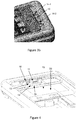
- the figure 2a is a basic sectional view of the implementation of the movable male connector in translation.
- the figure 2b represents a view from above.
- the connector (11) is mounted on a support (13).
- the support (13) is movable in a given direction.
- the general principle is to provide the support with a groove (15) complementary to a tongue (not shown). When it is placed on the tongue, the support can only slide in one direction, which is the direction of insertion and withdrawal of the payment terminal.
- the groove is not required. Any other sliding means, such as a slide, can also be used, for example in connection with a reception rail.
- the section of it is not necessarily parallelepipedic. This section can be semi-circular or triangular.
- the connector (11) for its part is connected to a motherboard or a power supply card of the payment device via a flex (12).
- This flex (12) makes it possible to ensure a displacement of the support and a permanent connectivity of the connector.
- the connector support in a complementary manner, is associated with return means (MR) (for example a spring or a spring blade), making it possible to put the support in abutment against an abutment geometry (a stop tooth) when no terminal is inserted into the receiving slot. More precisely, when no terminal is in the housing, the support is pushed into abutment so that it is held in a first position, called the waiting position. When a terminal is inserted, the terminal exerts a pressure on the support via the male connector. The support slides during insertion to a second position, called the operating position. The action of the return means is annihilated by closing the hatch for insertion of the terminal. Of course, this is an example of implementation. It is quite possible not to use recall means without affecting the benefits provided by this technique.
- MR return means
- the addition of the mobile male connector has two advantages: the first advantage is related to the fact that the male connector of the box is visible when no communication terminal is inserted. It is thus easy to check the status of this male connector and thus detect on the one hand a deterioration thereof and on the other hand a possible fraud attempt. There are indeed fraud devices such as on connectors that are placed or plugged into the existing male connector and that allow to intercept and / or modify data passing on it via this connector.
- the second advantage is related to the insertion and removal of the communication terminal.
- the movable male connector in translation makes it possible, during the insertion of the communication terminal, firstly to visualize the insertion step and to note (or not) that the male connector fits correctly into the connector. female. Thus, it prevents damage to both the male connector and the female connector (it may indeed be that the female connector of the terminal of communication that is deteriorated, and this deterioration may not be immediately perceived by the user).
- the movable male connector in translation also allows a progressive insertion of the male connector into the female connector.
- the mobility in translation makes it possible to insert the communication terminal in the same movement as the recoil movement of the movable male connector in translation as it is inserted.
- this progressive effect can also be increased, according to one embodiment, by the addition, between the mobile connector and the bottom of the housing, a biasing means (spring type, spring blade) which allows ensure a certain strength of resistance to insertion.
- the movable male connector in translation makes it possible, during the extraction of the communication terminal, to facilitate the translational movement of the communication terminal.
- the separation of the female connector of the communication terminal and the male connector of the housing may present some difficulty (as explained above).
- the mobility of the connector is a simple and effective answer to this problem: this mobility makes it possible to perform a simple translational movement; the communication terminal and the movable connector slide together, being fitted into each other to an end point of the movable connector; this translation makes it possible to create a vacuum, within the case, around the base of the communication terminal. This vacuum can be advantageously used to insert a finger or an object which is then used to push the communication terminal out of the box.
- the terminal can also be extracted by pulling on the top of the terminal (by exerting pressure with two fingers on the edge of the terminal) and pulling this one.
- this sliding effect can be further increased, according to one embodiment, by adding, between the movable connector and the bottom of the housing, a biasing means (spring type, spring blade) which ensures a some force pushed to the extraction of the communication terminal.
- a biasing means spring type, spring blade
- This force can thus be exerted as soon as the insertion / extraction hatch of the communication terminal is opened: when the hatch is open, the return means can then exert its pushing force without obstacle, so that the male connector can take up a starting position.
- the restoring force exerted is adapted according to whether it is desired for the mobile connector in translation to be able to extract the communication terminal alone or that it constitutes only a help to the thrust of the terminal out. housing.
- This sliding connector (10) comprises a male connector (11) connected to a motherboard (not shown) via a flexible printed circuit (12).
- This male connector (11) is metallic and is fixed on a base (13) movable in translation, plastic.
- the connector (11) is, in this embodiment, fixed to the base (13) movable through for example two trox screws (14-1, 14-2) located on either side of the base (13) and on both sides of the connector (11).
- the type of fastener or screw used is not necessarily of great importance. However, given the thrust and traction forces exerted, the use of trox screws may be advantageous for their adaptation to plastics.
- the base (13), movable in translation comprises a base (14). For clarity, it is base and base are merged.
- This base comprises, in its center, a groove (15) extending longitudinally in the sliding axis of the connector (10).
- This groove (15) serves to shape the sliding axis of the movable connector (10).
- the base is placed on a flat surface (16), comprising a tongue (17) shaped to fit into the groove (15) of the base (14) and ensure good stability and movement only in the longitudinal direction .
- the base also includes two retention fins, extending from both sides of the base perpendicularly to the groove. These two fins are used to hold the mobile connector in place and prevent it from coming out of its housing unexpectedly.
- the flat surface (16) of the receiving housing is in a plane (18) slightly lowered relative to the general plane (19) of reception of the communication terminal within the housing. This makes it possible to protect the translation plane of the mobile connector with a concealment plate (20) which, consequently, lies in the general plane (19) of reception of the communication terminal.
- the flat surface of the receiving housing also includes an abutment tooth (21) for stopping the translational movement of the movable connector (10). Furthermore, at the end of the stroke, at the stop tooth, two lateral orifices (22-1, 22-2) are also arranged to allow the extraction of the mobile connector if necessary (such as a maintenance for example). , when the connector is damaged). These two holes allow to extract the connector to a desired location, where a location is arranged for the retention fins.
Landscapes
- Engineering & Computer Science (AREA)
- Theoretical Computer Science (AREA)
- Physics & Mathematics (AREA)
- General Physics & Mathematics (AREA)
- General Engineering & Computer Science (AREA)
- Human Computer Interaction (AREA)
- Signal Processing (AREA)
- Computer Hardware Design (AREA)
- Computer Networks & Wireless Communication (AREA)
- Business, Economics & Management (AREA)
- Accounting & Taxation (AREA)
- Strategic Management (AREA)
- General Business, Economics & Management (AREA)
- Details Of Connecting Devices For Male And Female Coupling (AREA)
- Telephone Set Structure (AREA)
- Coupling Device And Connection With Printed Circuit (AREA)
Claims (6)
- Vorrichtung zum Anschließen (10) eines Kommunikationsendgeräts, wobei die Vorrichtung aufweist:- eine ebene Fläche (16),- einen Stecker (11), der dazu bestimmt ist, an eine Buchse des Kommunikationsendgeräts angeschlossen zu werden,- eine bewegliche Basis (13), auf der der Stecker (11) befestigt ist, wobei die bewegliche Basis auf der ebenen Fläche (16) angeordnet ist, und- eine Nut, die in der beweglichen Basis (13) ausgebildet ist, und eine entsprechende Lasche auf der ebenen Fläche (16), die sich in Längsrichtung entlang einer Gleitachse erstreckt, wobei die bewegliche Basis auf der ebenen Fläche entlang der Gleitachse gleiten kann, die einer Einschiebe- und Entnahmerichtung des Kommunikationsendgeräts in die Vorrichtung und aus dieser heraus entspricht.
- Vorrichtung nach Anspruch 1, dadurch gekennzeichnet, dass die Basis ferner mindestens ein Rückstellmittel aufweist.
- Vorrichtung nach Anspruch 1, dadurch gekennzeichnet, dass der Stecker ein Micro-USB-Stecker ist.
- Vorrichtung nach Anspruch 1, dadurch gekennzeichnet, dass der Stecker ein Lightning-Stecker ist.
- Vorrichtung nach Anspruch 1, dadurch gekennzeichnet, dass der Stecker ein USB-Typ-C-Stecker ist.
- Zahlungsvorrichtung, umfassend:- ein Zahlungsendgerät,- eine Aufnahme zum Einfügen eines Kommunikationsendgeräts in das Zahlungsendgerät,dadurch gekennzeichnet, dass sie in der Aufnahme zum Einfügen eine Vorrichtung zum Anschließen nach einem der vorhergehenden Ansprüche aufweist.
Applications Claiming Priority (1)
| Application Number | Priority Date | Filing Date | Title |
|---|---|---|---|
| FR1459998A FR3027465B1 (fr) | 2014-10-17 | 2014-10-17 | Dispositif d'insertion de terminal |
Publications (2)
| Publication Number | Publication Date |
|---|---|
| EP3010211A1 EP3010211A1 (de) | 2016-04-20 |
| EP3010211B1 true EP3010211B1 (de) | 2019-11-27 |
Family
ID=52273273
Family Applications (1)
| Application Number | Title | Priority Date | Filing Date |
|---|---|---|---|
| EP15190288.9A Active EP3010211B1 (de) | 2014-10-17 | 2015-10-16 | Vorrichtung zum einschieben eines endgeräts |
Country Status (7)
| Country | Link |
|---|---|
| US (1) | US9648156B2 (de) |
| EP (1) | EP3010211B1 (de) |
| BR (1) | BR102015026400A2 (de) |
| CA (1) | CA2908727C (de) |
| ES (1) | ES2773582T3 (de) |
| FR (1) | FR3027465B1 (de) |
| RU (1) | RU2015144594A (de) |
Families Citing this family (3)
| Publication number | Priority date | Publication date | Assignee | Title |
|---|---|---|---|---|
| WO2016025938A2 (en) * | 2014-08-15 | 2016-02-18 | Peri, Inc. | Mobile device case |
| FR3057382B1 (fr) * | 2016-10-07 | 2018-11-09 | Ingenico Group | Systeme de conversion d'un terminal de paiement electronique mobile en terminal de paiement electronique fixe |
| CN210838302U (zh) | 2016-10-07 | 2020-06-23 | 菲力尔系统公司 | 电子模块 |
Citations (1)
| Publication number | Priority date | Publication date | Assignee | Title |
|---|---|---|---|---|
| US20130050934A1 (en) * | 2011-08-24 | 2013-02-28 | Hon Hai Precision Industry Co., Ltd. | Docking station |
Family Cites Families (8)
| Publication number | Priority date | Publication date | Assignee | Title |
|---|---|---|---|---|
| US20070263348A1 (en) * | 2005-11-02 | 2007-11-15 | Dei Headquarters Inc. | Versatile portable electronic device docking station with slidable connector |
| DE502007005233D1 (de) * | 2006-11-13 | 2010-11-11 | Peiker Acustic Gmbh & Co Kg | Haltevorrichtung für ein elektronisches gerät |
| DE102007037944B4 (de) | 2007-08-11 | 2010-04-08 | Paragon Ag | Cradle für Mobiltelefone |
| CA3184461A1 (en) * | 2009-02-10 | 2010-09-02 | 4361423 Canada Inc. | Apparatus and method for commercial transactions using a communication device |
| FR2968433B1 (fr) * | 2010-12-07 | 2016-06-24 | Cie Ind Et Financiere D'ingenierie Ingenico | Dispositif de paiement electronique apte a recevoir et maintenir un telephone portable. |
| WO2013033573A2 (en) * | 2011-09-02 | 2013-03-07 | Sdi Technologies, Inc. | Adjustable docking apparatus |
| US9093849B2 (en) * | 2013-01-07 | 2015-07-28 | Superior Communications, Inc. | Universal charging dock with a wall mount |
| US9665125B2 (en) * | 2014-03-28 | 2017-05-30 | Intel Corporation | Magnetic attachment mechanism for an electronic device |
-
2014
- 2014-10-17 FR FR1459998A patent/FR3027465B1/fr active Active
-
2015
- 2015-10-14 CA CA2908727A patent/CA2908727C/en active Active
- 2015-10-16 RU RU2015144594A patent/RU2015144594A/ru not_active Application Discontinuation
- 2015-10-16 BR BR102015026400A patent/BR102015026400A2/pt not_active Application Discontinuation
- 2015-10-16 ES ES15190288T patent/ES2773582T3/es active Active
- 2015-10-16 EP EP15190288.9A patent/EP3010211B1/de active Active
- 2015-10-19 US US14/886,803 patent/US9648156B2/en active Active
Patent Citations (1)
| Publication number | Priority date | Publication date | Assignee | Title |
|---|---|---|---|---|
| US20130050934A1 (en) * | 2011-08-24 | 2013-02-28 | Hon Hai Precision Industry Co., Ltd. | Docking station |
Also Published As
| Publication number | Publication date |
|---|---|
| BR102015026400A2 (pt) | 2016-04-19 |
| ES2773582T3 (es) | 2020-07-13 |
| US9648156B2 (en) | 2017-05-09 |
| US20160112558A1 (en) | 2016-04-21 |
| RU2015144594A (ru) | 2017-04-24 |
| FR3027465A1 (fr) | 2016-04-22 |
| CA2908727A1 (en) | 2016-04-17 |
| CA2908727C (en) | 2023-03-14 |
| FR3027465B1 (fr) | 2018-04-06 |
| EP3010211A1 (de) | 2016-04-20 |
Similar Documents
| Publication | Publication Date | Title |
|---|---|---|
| FR3027462A1 (fr) | Dispositif de solidarisation de cables de rechargement electrique | |
| CN104716501B (zh) | 具有固持装置的移动终端 | |
| EP3010211B1 (de) | Vorrichtung zum einschieben eines endgeräts | |
| US9246249B2 (en) | Card connector for different specifications of electronic cards | |
| WO2009055062A3 (en) | Card connector for receiving multiple cards | |
| EP3326108B1 (de) | Kompaktkartenleser | |
| FR2903515A3 (fr) | Ensemble carte memoire | |
| EP0338900A1 (de) | Vorrichtung zur elektrischen Kontaktgabe von auf zwei Elemente verteilten Leitern und insbesondere zwischen denen einer Speicherkarte und deren Leseeinrichtung | |
| CN104735177A (zh) | 固持装置及具有固持装置的移动终端 | |
| FR2714989A1 (fr) | Dispositif de connexion de carte à mémoire. | |
| US20180219312A1 (en) | Withdrawable-card-tray position-fixing structure for electronic device | |
| CN207518578U (zh) | 一种防止卡托丢失的卡座结构 | |
| EP0263746A2 (de) | System zum Abtasten von Identifikationskarten mit elektrischen Kontakten | |
| US7988472B2 (en) | Electronic device | |
| BE1024236B9 (fr) | Dispositif d'affichage comprenant au moins un ecran mobile pour utilisation avec ordinateur portable | |
| CN106558780B (zh) | 卡连接器和连接器组件 | |
| EP4000008B1 (de) | Zahlkartenlesesystem mit einer schutzklappe | |
| EP2661790A1 (de) | Elektronische vorrichtung mit magnetischer halterung einer elektronischen komponente | |
| FR2976376A1 (fr) | Ensemble usb comportant une cle usb amelioree | |
| WO2000077715A1 (fr) | Extension pour module electronique de type pcmcia | |
| CN2741226Y (zh) | 具推入/顶出功能的卡片连接器 | |
| CN2917007Y (zh) | 连接器防卡脱落的结构改良 | |
| CN105576442B (zh) | 卡槽结构 | |
| CN101777133B (zh) | 一种读卡器组件 | |
| WO2000026845A1 (fr) | Lecteur de carte a puce a connecteur flottant |
Legal Events
| Date | Code | Title | Description |
|---|---|---|---|
| PUAI | Public reference made under article 153(3) epc to a published international application that has entered the european phase |
Free format text: ORIGINAL CODE: 0009012 |
|
| AK | Designated contracting states |
Kind code of ref document: A1 Designated state(s): AL AT BE BG CH CY CZ DE DK EE ES FI FR GB GR HR HU IE IS IT LI LT LU LV MC MK MT NL NO PL PT RO RS SE SI SK SM TR |
|
| AX | Request for extension of the european patent |
Extension state: BA ME |
|
| 17P | Request for examination filed |
Effective date: 20161020 |
|
| RBV | Designated contracting states (corrected) |
Designated state(s): AL AT BE BG CH CY CZ DE DK EE ES FI FR GB GR HR HU IE IS IT LI LT LU LV MC MK MT NL NO PL PT RO RS SE SI SK SM TR |
|
| STAA | Information on the status of an ep patent application or granted ep patent |
Free format text: STATUS: EXAMINATION IS IN PROGRESS |
|
| 17Q | First examination report despatched |
Effective date: 20181122 |
|
| RIC1 | Information provided on ipc code assigned before grant |
Ipc: G06F 13/42 20060101ALI20190521BHEP Ipc: H04M 1/04 20060101AFI20190521BHEP Ipc: H04M 1/725 20060101ALI20190521BHEP Ipc: G06Q 20/32 20120101ALI20190521BHEP Ipc: G07F 7/08 20060101ALI20190521BHEP Ipc: G06F 13/40 20060101ALI20190521BHEP Ipc: H01R 24/60 20110101ALI20190521BHEP Ipc: H01R 107/00 20060101ALI20190521BHEP Ipc: G06F 1/16 20060101ALI20190521BHEP |
|
| GRAP | Despatch of communication of intention to grant a patent |
Free format text: ORIGINAL CODE: EPIDOSNIGR1 |
|
| STAA | Information on the status of an ep patent application or granted ep patent |
Free format text: STATUS: GRANT OF PATENT IS INTENDED |
|
| INTG | Intention to grant announced |
Effective date: 20190628 |
|
| GRAS | Grant fee paid |
Free format text: ORIGINAL CODE: EPIDOSNIGR3 |
|
| GRAA | (expected) grant |
Free format text: ORIGINAL CODE: 0009210 |
|
| STAA | Information on the status of an ep patent application or granted ep patent |
Free format text: STATUS: THE PATENT HAS BEEN GRANTED |
|
| AK | Designated contracting states |
Kind code of ref document: B1 Designated state(s): AL AT BE BG CH CY CZ DE DK EE ES FI FR GB GR HR HU IE IS IT LI LT LU LV MC MK MT NL NO PL PT RO RS SE SI SK SM TR |
|
| REG | Reference to a national code |
Ref country code: GB Ref legal event code: FG4D Free format text: NOT ENGLISH |
|
| REG | Reference to a national code |
Ref country code: CH Ref legal event code: EP |
|
| REG | Reference to a national code |
Ref country code: AT Ref legal event code: REF Ref document number: 1208023 Country of ref document: AT Kind code of ref document: T Effective date: 20191215 |
|
| REG | Reference to a national code |
Ref country code: DE Ref legal event code: R096 Ref document number: 602015042416 Country of ref document: DE |
|
| REG | Reference to a national code |
Ref country code: IE Ref legal event code: FG4D Free format text: LANGUAGE OF EP DOCUMENT: FRENCH |
|
| REG | Reference to a national code |
Ref country code: NL Ref legal event code: MP Effective date: 20191127 |
|
| REG | Reference to a national code |
Ref country code: LT Ref legal event code: MG4D |
|
| PG25 | Lapsed in a contracting state [announced via postgrant information from national office to epo] |
Ref country code: NL Free format text: LAPSE BECAUSE OF FAILURE TO SUBMIT A TRANSLATION OF THE DESCRIPTION OR TO PAY THE FEE WITHIN THE PRESCRIBED TIME-LIMIT Effective date: 20191127 Ref country code: SE Free format text: LAPSE BECAUSE OF FAILURE TO SUBMIT A TRANSLATION OF THE DESCRIPTION OR TO PAY THE FEE WITHIN THE PRESCRIBED TIME-LIMIT Effective date: 20191127 Ref country code: LV Free format text: LAPSE BECAUSE OF FAILURE TO SUBMIT A TRANSLATION OF THE DESCRIPTION OR TO PAY THE FEE WITHIN THE PRESCRIBED TIME-LIMIT Effective date: 20191127 Ref country code: BG Free format text: LAPSE BECAUSE OF FAILURE TO SUBMIT A TRANSLATION OF THE DESCRIPTION OR TO PAY THE FEE WITHIN THE PRESCRIBED TIME-LIMIT Effective date: 20200227 Ref country code: FI Free format text: LAPSE BECAUSE OF FAILURE TO SUBMIT A TRANSLATION OF THE DESCRIPTION OR TO PAY THE FEE WITHIN THE PRESCRIBED TIME-LIMIT Effective date: 20191127 Ref country code: NO Free format text: LAPSE BECAUSE OF FAILURE TO SUBMIT A TRANSLATION OF THE DESCRIPTION OR TO PAY THE FEE WITHIN THE PRESCRIBED TIME-LIMIT Effective date: 20200227 Ref country code: GR Free format text: LAPSE BECAUSE OF FAILURE TO SUBMIT A TRANSLATION OF THE DESCRIPTION OR TO PAY THE FEE WITHIN THE PRESCRIBED TIME-LIMIT Effective date: 20200228 Ref country code: LT Free format text: LAPSE BECAUSE OF FAILURE TO SUBMIT A TRANSLATION OF THE DESCRIPTION OR TO PAY THE FEE WITHIN THE PRESCRIBED TIME-LIMIT Effective date: 20191127 |
|
| PG25 | Lapsed in a contracting state [announced via postgrant information from national office to epo] |
Ref country code: RS Free format text: LAPSE BECAUSE OF FAILURE TO SUBMIT A TRANSLATION OF THE DESCRIPTION OR TO PAY THE FEE WITHIN THE PRESCRIBED TIME-LIMIT Effective date: 20191127 Ref country code: IS Free format text: LAPSE BECAUSE OF FAILURE TO SUBMIT A TRANSLATION OF THE DESCRIPTION OR TO PAY THE FEE WITHIN THE PRESCRIBED TIME-LIMIT Effective date: 20200327 Ref country code: HR Free format text: LAPSE BECAUSE OF FAILURE TO SUBMIT A TRANSLATION OF THE DESCRIPTION OR TO PAY THE FEE WITHIN THE PRESCRIBED TIME-LIMIT Effective date: 20191127 |
|
| PG25 | Lapsed in a contracting state [announced via postgrant information from national office to epo] |
Ref country code: AL Free format text: LAPSE BECAUSE OF FAILURE TO SUBMIT A TRANSLATION OF THE DESCRIPTION OR TO PAY THE FEE WITHIN THE PRESCRIBED TIME-LIMIT Effective date: 20191127 |
|
| REG | Reference to a national code |
Ref country code: ES Ref legal event code: FG2A Ref document number: 2773582 Country of ref document: ES Kind code of ref document: T3 Effective date: 20200713 |
|
| PG25 | Lapsed in a contracting state [announced via postgrant information from national office to epo] |
Ref country code: CZ Free format text: LAPSE BECAUSE OF FAILURE TO SUBMIT A TRANSLATION OF THE DESCRIPTION OR TO PAY THE FEE WITHIN THE PRESCRIBED TIME-LIMIT Effective date: 20191127 Ref country code: RO Free format text: LAPSE BECAUSE OF FAILURE TO SUBMIT A TRANSLATION OF THE DESCRIPTION OR TO PAY THE FEE WITHIN THE PRESCRIBED TIME-LIMIT Effective date: 20191127 Ref country code: DK Free format text: LAPSE BECAUSE OF FAILURE TO SUBMIT A TRANSLATION OF THE DESCRIPTION OR TO PAY THE FEE WITHIN THE PRESCRIBED TIME-LIMIT Effective date: 20191127 Ref country code: PT Free format text: LAPSE BECAUSE OF FAILURE TO SUBMIT A TRANSLATION OF THE DESCRIPTION OR TO PAY THE FEE WITHIN THE PRESCRIBED TIME-LIMIT Effective date: 20200419 Ref country code: EE Free format text: LAPSE BECAUSE OF FAILURE TO SUBMIT A TRANSLATION OF THE DESCRIPTION OR TO PAY THE FEE WITHIN THE PRESCRIBED TIME-LIMIT Effective date: 20191127 |
|
| REG | Reference to a national code |
Ref country code: DE Ref legal event code: R097 Ref document number: 602015042416 Country of ref document: DE |
|
| PG25 | Lapsed in a contracting state [announced via postgrant information from national office to epo] |
Ref country code: SM Free format text: LAPSE BECAUSE OF FAILURE TO SUBMIT A TRANSLATION OF THE DESCRIPTION OR TO PAY THE FEE WITHIN THE PRESCRIBED TIME-LIMIT Effective date: 20191127 Ref country code: SK Free format text: LAPSE BECAUSE OF FAILURE TO SUBMIT A TRANSLATION OF THE DESCRIPTION OR TO PAY THE FEE WITHIN THE PRESCRIBED TIME-LIMIT Effective date: 20191127 |
|
| REG | Reference to a national code |
Ref country code: AT Ref legal event code: MK05 Ref document number: 1208023 Country of ref document: AT Kind code of ref document: T Effective date: 20191127 |
|
| PLBE | No opposition filed within time limit |
Free format text: ORIGINAL CODE: 0009261 |
|
| STAA | Information on the status of an ep patent application or granted ep patent |
Free format text: STATUS: NO OPPOSITION FILED WITHIN TIME LIMIT |
|
| 26N | No opposition filed |
Effective date: 20200828 |
|
| PG25 | Lapsed in a contracting state [announced via postgrant information from national office to epo] |
Ref country code: AT Free format text: LAPSE BECAUSE OF FAILURE TO SUBMIT A TRANSLATION OF THE DESCRIPTION OR TO PAY THE FEE WITHIN THE PRESCRIBED TIME-LIMIT Effective date: 20191127 Ref country code: SI Free format text: LAPSE BECAUSE OF FAILURE TO SUBMIT A TRANSLATION OF THE DESCRIPTION OR TO PAY THE FEE WITHIN THE PRESCRIBED TIME-LIMIT Effective date: 20191127 Ref country code: PL Free format text: LAPSE BECAUSE OF FAILURE TO SUBMIT A TRANSLATION OF THE DESCRIPTION OR TO PAY THE FEE WITHIN THE PRESCRIBED TIME-LIMIT Effective date: 20191127 |
|
| PG25 | Lapsed in a contracting state [announced via postgrant information from national office to epo] |
Ref country code: IT Free format text: LAPSE BECAUSE OF FAILURE TO SUBMIT A TRANSLATION OF THE DESCRIPTION OR TO PAY THE FEE WITHIN THE PRESCRIBED TIME-LIMIT Effective date: 20191127 |
|
| REG | Reference to a national code |
Ref country code: CH Ref legal event code: PL |
|
| PG25 | Lapsed in a contracting state [announced via postgrant information from national office to epo] |
Ref country code: LU Free format text: LAPSE BECAUSE OF NON-PAYMENT OF DUE FEES Effective date: 20201016 Ref country code: MC Free format text: LAPSE BECAUSE OF FAILURE TO SUBMIT A TRANSLATION OF THE DESCRIPTION OR TO PAY THE FEE WITHIN THE PRESCRIBED TIME-LIMIT Effective date: 20191127 |
|
| REG | Reference to a national code |
Ref country code: BE Ref legal event code: MM Effective date: 20201031 |
|
| PG25 | Lapsed in a contracting state [announced via postgrant information from national office to epo] |
Ref country code: CH Free format text: LAPSE BECAUSE OF NON-PAYMENT OF DUE FEES Effective date: 20201031 Ref country code: BE Free format text: LAPSE BECAUSE OF NON-PAYMENT OF DUE FEES Effective date: 20201031 Ref country code: LI Free format text: LAPSE BECAUSE OF NON-PAYMENT OF DUE FEES Effective date: 20201031 |
|
| PG25 | Lapsed in a contracting state [announced via postgrant information from national office to epo] |
Ref country code: IE Free format text: LAPSE BECAUSE OF NON-PAYMENT OF DUE FEES Effective date: 20201016 |
|
| REG | Reference to a national code |
Ref country code: GB Ref legal event code: 732E Free format text: REGISTERED BETWEEN 20220127 AND 20220202 |
|
| PG25 | Lapsed in a contracting state [announced via postgrant information from national office to epo] |
Ref country code: TR Free format text: LAPSE BECAUSE OF FAILURE TO SUBMIT A TRANSLATION OF THE DESCRIPTION OR TO PAY THE FEE WITHIN THE PRESCRIBED TIME-LIMIT Effective date: 20191127 Ref country code: MT Free format text: LAPSE BECAUSE OF FAILURE TO SUBMIT A TRANSLATION OF THE DESCRIPTION OR TO PAY THE FEE WITHIN THE PRESCRIBED TIME-LIMIT Effective date: 20191127 Ref country code: CY Free format text: LAPSE BECAUSE OF FAILURE TO SUBMIT A TRANSLATION OF THE DESCRIPTION OR TO PAY THE FEE WITHIN THE PRESCRIBED TIME-LIMIT Effective date: 20191127 |
|
| PG25 | Lapsed in a contracting state [announced via postgrant information from national office to epo] |
Ref country code: MK Free format text: LAPSE BECAUSE OF FAILURE TO SUBMIT A TRANSLATION OF THE DESCRIPTION OR TO PAY THE FEE WITHIN THE PRESCRIBED TIME-LIMIT Effective date: 20191127 |
|
| REG | Reference to a national code |
Ref country code: DE Ref legal event code: R081 Ref document number: 602015042416 Country of ref document: DE Owner name: BANKS AND ACQUIRES INTERNATIONAL HOLDING, FR Free format text: FORMER OWNER: INGENICO GROUP, PARIS, FR Ref country code: DE Ref legal event code: R082 Ref document number: 602015042416 Country of ref document: DE Representative=s name: STUMPF PATENTANWAELTE PARTGMBB, DE Ref country code: DE Ref legal event code: R081 Ref document number: 602015042416 Country of ref document: DE Owner name: BANKS AND ACQUIRERS INTERNATIONAL HOLDING, FR Free format text: FORMER OWNER: INGENICO GROUP, PARIS, FR |
|
| REG | Reference to a national code |
Ref country code: DE Ref legal event code: R081 Ref document number: 602015042416 Country of ref document: DE Owner name: BANKS AND ACQUIRERS INTERNATIONAL HOLDING, FR Free format text: FORMER OWNER: BANKS AND ACQUIRES INTERNATIONAL HOLDING, SURESNES, FR |
|
| REG | Reference to a national code |
Ref country code: ES Ref legal event code: PC2A Owner name: BANKS AND ACQUIRERS INTERNATIONAL HOLDING Effective date: 20250929 |
|
| PGFP | Annual fee paid to national office [announced via postgrant information from national office to epo] |
Ref country code: DE Payment date: 20251021 Year of fee payment: 11 |
|
| PGFP | Annual fee paid to national office [announced via postgrant information from national office to epo] |
Ref country code: GB Payment date: 20251022 Year of fee payment: 11 |
|
| PGFP | Annual fee paid to national office [announced via postgrant information from national office to epo] |
Ref country code: FR Payment date: 20251030 Year of fee payment: 11 |
|
| PGFP | Annual fee paid to national office [announced via postgrant information from national office to epo] |
Ref country code: ES Payment date: 20251210 Year of fee payment: 11 |
|
| P01 | Opt-out of the competence of the unified patent court (upc) registered |
Free format text: CASE NUMBER: UPC_APP_0000325_3010211/2026 Effective date: 20260106 |