EP3010425B1 - Chirurgischer clip-applikator - Google Patents
Chirurgischer clip-applikator Download PDFInfo
- Publication number
- EP3010425B1 EP3010425B1 EP14732127.7A EP14732127A EP3010425B1 EP 3010425 B1 EP3010425 B1 EP 3010425B1 EP 14732127 A EP14732127 A EP 14732127A EP 3010425 B1 EP3010425 B1 EP 3010425B1
- Authority
- EP
- European Patent Office
- Prior art keywords
- clip
- individual
- magazine
- handle
- applicator
- Prior art date
- Legal status (The legal status is an assumption and is not a legal conclusion. Google has not performed a legal analysis and makes no representation as to the accuracy of the status listed.)
- Active
Links
Images


Classifications
-
- A—HUMAN NECESSITIES
- A61—MEDICAL OR VETERINARY SCIENCE; HYGIENE
- A61B—DIAGNOSIS; SURGERY; IDENTIFICATION
- A61B17/00—Surgical instruments, devices or methods
- A61B17/10—Surgical instruments, devices or methods for applying or removing wound clamps, e.g. containing only one clamp or staple; Wound clamp magazines
- A61B17/105—Wound clamp magazines
-
- A—HUMAN NECESSITIES
- A61—MEDICAL OR VETERINARY SCIENCE; HYGIENE
- A61B—DIAGNOSIS; SURGERY; IDENTIFICATION
- A61B17/00—Surgical instruments, devices or methods
- A61B17/12—Surgical instruments, devices or methods for ligaturing or otherwise compressing tubular parts of the body, e.g. blood vessels or umbilical cord
- A61B17/128—Surgical instruments, devices or methods for ligaturing or otherwise compressing tubular parts of the body, e.g. blood vessels or umbilical cord for applying or removing clamps or clips
-
- A—HUMAN NECESSITIES
- A61—MEDICAL OR VETERINARY SCIENCE; HYGIENE
- A61B—DIAGNOSIS; SURGERY; IDENTIFICATION
- A61B17/00—Surgical instruments, devices or methods
- A61B2017/0023—Surgical instruments, devices or methods disposable
-
- A—HUMAN NECESSITIES
- A61—MEDICAL OR VETERINARY SCIENCE; HYGIENE
- A61B—DIAGNOSIS; SURGERY; IDENTIFICATION
- A61B17/00—Surgical instruments, devices or methods
- A61B2017/0042—Surgical instruments, devices or methods with special provisions for gripping
- A61B2017/00424—Surgical instruments, devices or methods with special provisions for gripping ergonomic, e.g. fitting in fist
-
- A—HUMAN NECESSITIES
- A61—MEDICAL OR VETERINARY SCIENCE; HYGIENE
- A61B—DIAGNOSIS; SURGERY; IDENTIFICATION
- A61B17/00—Surgical instruments, devices or methods
- A61B2017/0046—Surgical instruments, devices or methods with a releasable handle; with handle and operating part separable
-
- A—HUMAN NECESSITIES
- A61—MEDICAL OR VETERINARY SCIENCE; HYGIENE
- A61B—DIAGNOSIS; SURGERY; IDENTIFICATION
- A61B17/00—Surgical instruments, devices or methods
- A61B2017/00477—Coupling
- A61B2017/00482—Coupling with a code
-
- A—HUMAN NECESSITIES
- A61—MEDICAL OR VETERINARY SCIENCE; HYGIENE
- A61B—DIAGNOSIS; SURGERY; IDENTIFICATION
- A61B17/00—Surgical instruments, devices or methods
- A61B17/28—Surgical forceps
- A61B17/29—Forceps for use in minimally invasive surgery
- A61B17/2909—Handles
- A61B2017/2912—Handles transmission of forces to actuating rod or piston
- A61B2017/2919—Handles transmission of forces to actuating rod or piston details of linkages or pivot points
- A61B2017/292—Handles transmission of forces to actuating rod or piston details of linkages or pivot points connection of actuating rod to handle, e.g. ball end in recess
-
- A—HUMAN NECESSITIES
- A61—MEDICAL OR VETERINARY SCIENCE; HYGIENE
- A61B—DIAGNOSIS; SURGERY; IDENTIFICATION
- A61B90/00—Instruments, implements or accessories specially adapted for surgery or diagnosis and not covered by any of the groups A61B1/00 - A61B50/00, e.g. for luxation treatment or for protecting wound edges
- A61B90/03—Automatic limiting or abutting means, e.g. for safety
- A61B2090/032—Automatic limiting or abutting means, e.g. for safety pressure limiting, e.g. hydrostatic
-
- A—HUMAN NECESSITIES
- A61—MEDICAL OR VETERINARY SCIENCE; HYGIENE
- A61B—DIAGNOSIS; SURGERY; IDENTIFICATION
- A61B2560/00—Constructional details of operational features of apparatus; Accessories for medical measuring apparatus
- A61B2560/04—Constructional details of apparatus
- A61B2560/0443—Modular apparatus
Definitions
- a generic clip applicator is, for example, from DE 20 2011 000 755 U1 known.
- This type of clip applicator can be used in open and endoscopic surgery to quickly and reliably connect tissue structures of a patient to be operated on by applying and then closing preferably U-shaped or V-shaped clips.
- U-shaped or V-shaped clips can be used to clamp off a patient's blood vessels quickly and safely.
- Different types of clips can be used here, which can differ, for example, in their shape, but also in their size and strength.
- this clip applicator can be provided comparatively inexpensively and also allows a comparatively safe application and closing of the clips, it would be desirable to improve the handling of the clip applicator.
- US Pat DE 44 29 084 C1 Another prior art is in US Pat DE 44 29 084 C1 described.
- the clip applicator described therein also enables a comparatively simple exchange of a clip magazine, which can be detachably inserted through a lateral opening in a tubular shaft of the clip applicator.
- the clip magazine is designed as a disposable part, while a handle part and the tubular shaft that can be attached to it are designed as reusable parts.
- This clip applicator also offers the possibility of attaching different tubular shafts, which differ from one another, for example, in their shaft length, to a single handle part.
- this clip applicator thus allows relatively flexible handling, it is still necessary to change both the tubular shaft and the clip magazine for the application of different types of clips. It is therefore also desirable to improve the handling of the clip applicator of the type described at the outset.
- a clip applicator which has a handle part and a clip magazine which can be attached thereto, both of which are designed as disposable parts.
- the clip magazine is integrated into a shaft of the clip applicator, with a different number of clips being held or stored and possibly applied by different shaft lengths.
- this clip applicator also does not offer the possibility of applying different types of clips with the same clip applicator, so that the desire continues to exist to improve the handling of the clip applicator of the type described above.
- the US 2011/024145 A1 discloses a surgical device (handle with actuating elements) for minimally invasive interventions and a force-limiting coupling.
- a coupling prevents excessive forces acting at the distal end of the surgical device, which could possibly cause damage to the patient.
- U.S. 4,611,595 A discloses a surgical clip applicator with a handle to which a magazine with surgical clips can be attached.
- the clip magazine is changeable.
- the invention is based on the object of creating a surgical clip applicator which can be provided comparatively inexpensively and in which handling is improved using means that are as simple as possible in terms of construction.
- One goal here is to improve the flexibility of the clip applicator with regard to the possibility of using different types of clips.
- a Another aim is to be able to provide components of the clip applicator that are designed as single-use parts as cost-effectively as possible.
- a universal handle of a surgical clip applicator on which an individual clip magazine, which has a crimping head and can be arbitrarily selected from a number of different clip magazines, can be mounted, such that the universal handle and the individual clip attached to it.
- Clip magazine for crimping individual clips in the crimping head and for conveying individual clips from a clip receiving section of the individual clip magazine via an individual feed path towards the crimping head.
- the universal handle has an integrated power transmission gear or linkage with at least one manually grippable handle (handle lever, scissor handle, etc.) as an actuating input part and with a coupling as an actuating output part to the individual clip magazine.
- An adaptation device is provided between the actuating input part and the actuating output part, which is adapted to compensate or adapt clip-related differences between the individual feed path of the currently attached individual clip magazine and the maximum actuation path of the actuating input part on the universal handle.
- the adaptation device is an overload protection for an interruption of the power transmission in the transmission, preferably in the form of a slip clutch or a release mechanism.
- the slip clutch can then be set to a slipping blade above the force required for conveying individual clips from the clip magazine via the individual feed path to the crimping head and below a predetermined actuating force that overloads the power transmission.
- a surgical clip applicator is proposed, with a universal handle described above and an individual clip magazine mountable thereon, which has a crimping head, a clip receiving section and a clip feed device for conveying individual clips from the clip receiving section via an individual feed path to the crimping head as a function of manual actuation of the universal handle.
- the individual clip magazine which can be selected as required from a large number of clip magazines for different clip types, has an integrated coding mechanism designed as a function of the clip type to be applied, with which at least the delivery path adapted to the respective clip type is or is determined.
- the coding mechanism has two limit stops to limit the movement of the clip feed device in both longitudinal directions.
- the clip advancing device is adapted to interact with a latching / engaging section at the distal end of an actuating / output part / output element on an adapter device of the universal handle.
- a single (universal) handle By integrating the coding mechanism to determine the delivery path adapted to the respective clip type in the clip magazine, it is possible to attach a large number of different clip magazines (detachable) to a single (universal) handle, to replace them if necessary, and to attach them in each case to apply stored clips.
- the essentially shaft-shaped clip magazines can have different shaft lengths.
- different clip types can also be stored in the different clip magazines, which clip types differ from one another, for example, in terms of their shape and / or size and / or strength. This means that a single (universal) handle can be combined with a large number, for example two, three, four, five or more, of different clip magazines in order to be able to apply different types of clips while maintaining the same handle.
- the invention thus effectively improves the handling of the clip applicator and the space available in the operating room, since different clip types can be applied with a single movement, simply by selecting and replacing the clip magazine, or different shaft lengths of the clip applicator by a simply replacing the clip magazine can be realized.
- the invention thus also effectively reduces the number of different clip applicators that have to be kept or made available in the operating room. In this way, the invention contributes to improving the clarity in the operating room.
- the coding mechanism integrated in the respective clip magazine advantageously has the effect that a smaller number of reusable handles have to be sterilized after an operation.
- the coding mechanism preferably has a clip feed device with at least one limit stop acting in the longitudinal direction of the clip feed device for at least partially defining the feed path.
- the clip feed device is a first component of the coding mechanism, which ensures the feed path of the individual clips.
- the clip feed device can be designed as a clip feed rod which is set up or configured so that with each manual actuation of the handle by a user and as a result of a longitudinal movement caused thereby, only one clip from the multitude of clips stored in the clip magazine is picked up and transported to or into the insertion tool.
- the clip feed device has two limit stops spaced apart from one another in the longitudinal direction / feed direction, the positions and / or spacing of which are adapted depending on the clip type to be applied so that a backward and a / or the forward movement of the clip feed device in each case exactly one single clip can be picked up from the clip magazine and transported exactly to the crimping head.
- the position of the limit stops depends in particular on the size and / or thickness and / or shape of the clip to be applied and, if applicable, on the number of clips to be kept available in the clip magazine and / or its shaft length.
- the magazine's internal mechanism for opening and closing the crimping head is also appropriately adapted to be operated via the handle. It is advantageous if the magazine's internal crimping head actuation mechanism requires a uniform actuation path / amount for all different magazines, so that its actuation by the coupled universal handle does not require an adaptation device as in the case of the individual feed device.
- the crimping head has a gate that controls the closing and opening, the position and / or geometric shape of which is adapted to the type of clip to be applied and / or to the shaft length of the clip magazine.
- the coulisse can be positioned or geometrically shaped on the crimping head in such a way that the closing movement of the crimping head differs from the closing movement of the crimping head with a comparatively small clip in the case of a comparatively large clip.
- the crimping head actuation mechanism on the magazine can then be standardized.
- the crimping head of the clip magazine is adapted to come into contact with the at least one limit stop of the clip feed device in order to thereby limit the backward and / or forward movement of the clip feed device.
- the crimping head of the clip magazine and the clip feed device of the clip magazine can work together in such a way that only a single clip is picked up from the clip magazine and transported to the application tool.
- the handle has the aforementioned overload protection which interacts with the coding mechanism of the clip magazine and which, when the handle is operated manually, damages the handle and / or the clip magazine attached to it due to excessive Operating forces prevented.
- This means that the flexible handling of the universally usable handle part is additionally improved by the fact that a (mechanical) overload protection is firmly integrated into the handle.
- the handle can be designed as a reusable part. This means that the handle, which can be used universally with different clip magazines, can continue to be used in several operations after sterilization.
- each of the large number of clip magazines can be designed as a disposable part.
- the handle and / or the clip magazine can have a color / symbol coding adapted to the clip type to be applied for visualizing the clip magazine that can be used with the handle.
- a housing of the clip magazine can be colored in a color that is assigned to a specific clip type.
- a correspondingly assignable Color coding must be appropriate. This color coding of the two components of the clip applicator that can be joined together enables particularly intuitive use of the clip applicator.
- a surgical clip applicator consists of the handle and the clip magazine.
- the clip magazine is manufactured / provided as a separate or separate component from the handle and can be releasably attached / mounted on this if necessary, the handle and the clip magazine attached to it interact to provide a tool for applying individual clips and a defined feed path for the clip transport of individual clips from the clip storage to the crimping head of the magazine.
- the clip magazine which can be selected as required from a multitude of different clip magazines for each different clip types, has an integrated coding mechanism designed as a function of the clip type to be applied, which at least defines the delivery path adapted to the respective clip type.
- the clip magazines from the large number of clip magazines can also be found in the Achieving shaft length or overall applicator length differ, which can be, for example, 240 mm, 290 mm or 340 mm.
- the universal handle can be configured, for example, to be combined with a clip magazine that stores 20 clips of the "small” size and leads to an applicator length of 240 mm when combined with one another, that is, when assembled.
- the same handle can also be configured to be combined with a clip magazine that stores 20 clips of the "medium” size and, when combined, leads to an applicator length of 240 mm.
- FIG. 1 shows in a perspective top view generally a clip applicator (clip applicator set) 1 according to the invention, which consists of a universal (reusable) handle 2 and a number of individually selectable, individual (single use) clip magazines, of which here a single clip magazine 4 is shown as an example.
- a clip applicator 1 can be used, for example, in open and / or endoscopic surgery in order to quickly and reliably connect tissue structures of a patient to one another connect or clamp blood vessels of a patient quickly and reliably.
- the handle 2 according to the following detailed description and the essentially shaft-shaped clip magazine 4 according to the following detailed description are generally each set up so that the clip magazine 4 selected as required from the plurality of clip magazines can be releasably attached to the handle 2 in order to jointly form the clip applicator 1 in this way.
- the handle 2 and the clip magazine 4 are shown here separately from one another.
- the handle 2 has on its distal end section (from the perspective of a user) a shaft 10 which is formed (materially) in one piece with the housing 2a or is fastened to it and has a U-shaped cross-section, into which a crimp release or locking device 12 in In the form of a longitudinally displaceable, U-shaped slide and a holding part 14 in the form of a bolt fixed (welded) to the shaft 10, which protrudes perpendicularly from the base of the U-shaped handle shaft 10 at a longitudinal center section.
- a shaft 10 which is formed (materially) in one piece with the housing 2a or is fastened to it and has a U-shaped cross-section, into which a crimp release or locking device 12 in In the form of a longitudinally displaceable, U-shaped slide and a holding part 14 in the form of a bolt fixed (welded) to the shaft 10, which protrudes perpendicularly from the base of the U-shaped handle shaft 10 at a longitudinal center section.
- the length and the width of the shaft 10 of the handle 2 are designed so that the essentially shaft-shaped clip magazine 4 can be inserted at least partially into the shaft 10 in such a way that the handle 2 and the clip magazine selected to match 4 in the assembled state result in a total clip applicator length of 240 mm to 340 mm, in this exemplary embodiment 240 mm.
- This driver unit 54 preferably has an internally longitudinally displaceable input element on which a connecting rod 56 is used to couple the two Handle lever 6, 8 is articulated to the actuating gear 54.
- the input element is operatively connected via an internal slip clutch 52 to an output element which is mounted so as to be relatively longitudinally displaceable and which has a latching / engaging section at its distal end for the clip feed device of the clip magazine 4 currently in use.
- the connecting rods 56 coupling the input element to the handle levers 6, 8 are oriented in the proximal direction starting from the handle levers 6, 8, in such a way that when the two handle levers 6, 8 are pressed together like a scissors handle, the input element and thus the output element via the slip clutch 52 Is displaced proximally in the housing 2a.
- Both handle levers 6, 8 are each coupled via a further connecting rod 58 to the locking device 12 in the form of the U-shaped slide mounted in the handle shaft 10.
- These two further connecting rods 58 are oriented opposite to the aforementioned connecting rods 56, so that when the two handle levers 6, 8 are pressed together in the manner of a scissors handle, the U-shaped slide 12 is displaced in the distal direction.
- the jaw part 20 (viewed in its longitudinal direction) has a (control) gate 24 and 26 on the left and right outer sides.
- the links 24, 26 and the closing device 12 are each set up to jointly define an opening and closing movement of the jaw part 20.
- the position and the geometric shape of the scenes 24, 26 of the jaw part 20 for the different clip magazines from the large number of clip magazines can be individually determined / determined, in particular depending on the selected clip magazine and / or the type of clip to be applied, since, depending on the clip magazine and / or clip type, a larger / smaller mouth opening on the crimping head 20 is necessary.
- the clip magazine 4 shown also has a clip feed device 38 in the form of a clip feed rod for receiving and delivering, that is to say transporting, isolated clips.
- the clip advancing device 38 is set up to interact with the jaw part 20 and is mounted displaceably relative to this in the longitudinal direction of the clip magazine 4 or in the longitudinal direction of the shaft 10 of the handle 2.
- This means that the feed device 38 has the function of receiving individual clips from the clip magazine 4 and of transporting them further in the distal longitudinal direction of the shaft 10.
- the clip advancing device 38 has a clip tongue 40 at its distal end, with which individual clips can be picked up and advanced or transported.
- the clip advancing device 38 has two in In the longitudinal direction of the same spaced-apart limit stops 42 and 44.
- the limit stops 42, 44 are shaped and dimensioned in such a way that they can each be connected to the crimping tool 22 in
- the limit stops 42, 44 are designed as a stamped / bent part in one piece with the clip feed device 38.
- the distance in the longitudinal direction between the two limit stops 42, 44 is dimensioned or selected and determined such that the clip tongue 40 in the event of a rearward movement of the clip feed device 38 (from the proximal point of view), i.e. a clip receiving movement of the clip feed device 38, exactly a single clip is picked up from the clip magazine 4, as will be explained in more detail below.
- the clip feed device 38 is shown in a position in which the proximal, that is to say the rear limit stop 44 in the clip feed direction, is in abutting contact with the crimping tool 22.
- FIG 4 which shows a perspective bottom view of a section of the clip magazine 4 in a partially dismantled state
- the clip feed device 38 is shown in a different position / position in which it the individual clip 46 from a clip storage section 48 of the clip magazine 4 for Can accommodate delivery or further transport in the direction of the jaw part 20 (crimping tool 22).
- the clip storage section 48 (from the distal point of view) is arranged behind the jaw part jaws 32, 34, so that a single clip 46 (from the distal point of view) has to be advanced or transported to the front in order to place it between the jaw part jaws 32, 34 to promote.
- the overload protection 50 can additionally ensure that a universal handle 2 with several from the plurality of Clip magazines can work together without the mechanics or the
- Figure 2 shows a perspective side view of the clip applicator 1 in the assembled state, that is to say in the functional state, in which the clip magazine 4 are fastened to one another by the interaction of the assembly device 16 and the holding device 18.
- the internal actuation mechanism 54 of the handle 2 is activated in such a way that the locking device 12, which is designed as a U-shaped slide, is displaced longitudinally in the distal direction.
- the locking device 12 is pushed over the connecting links 24, 26 of the jaw part 20, whereby its jaw part jaws 32, 34 are pressed towards one another, i.e. inward, and the crimping tool 22 is thus closed.
- the internal actuation mechanism 54 of the handle 2 is also actuated in such a way that the clip feed device 38 is displaced in a longitudinal movement (in the proximal direction) in the opposite direction to the locking device 12 until the front limit stop 42 strikes the fixed crimping tool 22 and, if necessary, the slip clutch 52 of the overload protection 50 is triggered.
- the internal actuation mechanism 54 of the handle 2 then holds the clip feed device 38 in this position until the jaw part jaws 32, 34 are spaced apart again by moving the closing device 12 back and the crimping tool 22 is thus opened again.
- a surgical clip applicator with a universal handle and with an individual clip magazine with an integrated crimping head / crimping tool, which can be releasably attached to the universal handle.
- the universal handle and the individual clip magazine attached to it work together to form a feed path that is defined for actuation or individually available for the clip transport of individual clips from a clip receiving section of the clip magazine to the crimping head.
- the individual clip magazine can be selected as required from a large number of clip magazines for different clip types, the clip magazine having an integrated coding mechanism designed as a function of the clip type to be applied which, in cooperation with the universal handle, at least affects the respective Specifies the delivery route adapted to the clip type.
Landscapes
- Health & Medical Sciences (AREA)
- Life Sciences & Earth Sciences (AREA)
- Surgery (AREA)
- Molecular Biology (AREA)
- Engineering & Computer Science (AREA)
- Biomedical Technology (AREA)
- Heart & Thoracic Surgery (AREA)
- Medical Informatics (AREA)
- Nuclear Medicine, Radiotherapy & Molecular Imaging (AREA)
- Animal Behavior & Ethology (AREA)
- General Health & Medical Sciences (AREA)
- Public Health (AREA)
- Veterinary Medicine (AREA)
- Reproductive Health (AREA)
- Vascular Medicine (AREA)
- Surgical Instruments (AREA)
Description
- Die Offenbarung betrifft einen chirurgischen Clip-Applikator, ein Clip-Magazin für den Clip-Applikator sowie einen Handgriff zur lösbaren Aufnahme des Clip-Magazins.
- Clip-Applikatoren sind chirurgische Instrumente zum Setzen (Applizieren) von Gewebeclips am Gewebe eines Patienten etwa zum Verschließen einer Naht oder eines Gefäßes. Dadurch entfällt ein aufwändiges Vernähen, was insbesondere bei von Außen schwer zugänglichen Operationsstellen vorteilhaft ist.
- Ein gattungsgemäßer Clip-Applikator ist beispielsweise aus der
DE 20 2011 000 755 U1 bekannt. Diese Art von Clip-Applikator kann in der offenen und in der endoskopischen Chirurgie eingesetzt werden, um Gewebestrukturen eines zu operierenden Patienten durch ein Anlegen und anschließendes Schließen von vorzugsweise U-förmigen oder V-förmigen Clips schnell und zuverlässig zu verbinden. Insbesondere kann ein solcher Clip-Applikator dazu verwendet werden, Blutgefäße eines Patienten schnell und sicher abzuklemmen. Hierbei können verschiedene Cliptypen zum Einsatz kommen, die sich beispielsweise in ihrer Form, aber auch in ihrer Größe und Stärke, unterscheiden können. - Der in der
DE 20 2011 000 755 U1 beschriebene Clip-Applikator deren Offenbarungsgehalt hiermit auch zum Gegenstand dieser Anmeldung gemacht wird, weist ein Handgriffteil auf, an dem ein Clip-Magazin mit einem integrierten Clipspeicher lösbar befestigt werden kann. Dabei ist das Handgriffteil dazu vorgesehen und entsprechend eingerichtet, um als wiederverwendbares Teil (Mehrweg-Teil) mehrfach benutzt zu werden. Dagegen ist das Clip-Magazin dafür vorgesehen und entsprechend eingerichtet, um als zu entsorgendes Teil (Einweg-Teil) nur solange verwendet zu werden, bis die im Clipspeicher des Clip-Magazins bevorrateten Clips aufgebraucht sind. - Obwohl dieser Clip-Applikator vergleichsweise kostengünstig bereitgestellt werden kann und auch ein vergleichsweise sicheres Anlegen und Schließen der Clips erlaubt, wäre es wünschenswert, die Handhabung des Clip-Applikators zu verbessern. Dieser Wunsch resultiert aus dem Umstand, dass das Handgriffteil dieses Clip-Applikators lediglich dafür vorgesehen ist, mit Clip-Magazinen derselben Bauart/der selben Clipart und Clipgröße kombiniert zu werden. In anderen Worten ausgedrückt, lässt sich mit ein und demselben Handgriffteil, trotz Austausch einzelner Clip-Magazine, nur genau ein bestimmter Cliptyp applizieren. Das heißt, dass im Operationssaal unter Umständen eine Vielzahl von verschieden Handgriffteilen sowie eine Vielzahl von verschiedenen Clip-Magazinen vorgehalten werden muss, von denen jede Kombination von Handgriffteil und Clip-Magazin für jeweils nur einen einzigen Cliptyp verwendet werden kann. Dies wirkt sich jedoch nachteilig auf die Platzverhältnisse und Übersichtlichkeit im Operationssaal aus.
- Ein anderer Stand der Technik ist in der
DE 44 29 084 C1 beschrieben. Der darin beschriebene Clip-Applikator ermöglicht ebenfalls ein vergleichsweise einfaches Auswechseln eines Clip-Magazins, das durch eine seitliche Durchbrechung in einen Rohrschaft des Clip-Applikators lösbar eingelegt werden kann. Dabei ist das Clip-Magazin als Einweg-Teil ausgebildet, während ein Handgriffteil und der daran befestigbare Rohrschaft als wiederverwendbare Teile ausgebildet sind. Weiter bietet dieser Clip-Applikator die Möglichkeit, unterschiedliche Rohrschäfte, die sich beispielsweise in ihrer Schaftlänge voneinander unterscheiden, an einem einzigen Handgriffteil zu befestigen. Obwohl dieser Clip-Applikator damit eine relativ flexible Handhabung erlaubt, ist es für die Applikation unterschiedlicher Cliptypen dennoch notwendig, sowohl den Rohrschaft, als auch das Clip-Magazin zu wechseln. Deshalb ist es weiterhin wünschenswert, die Handhabung des Clip-Applikators der eingangs beschriebenen Art zu verbessern. - Weiter ist aus der
US 6 599 298 B1 ein Clip-Applikator bekannt, der ein Handgriffteil und ein daran befestigbares Clip-Magazin aufweist, die beide jeweils als Einweg-Teil ausgebildet sind. Dabei ist das Clip-Magazin in einen Schaft des Clip-Applikators integiert, wobei durch unterschiedliche Schaftlängen eine unterschiedliche Anzahl von Clips vorgehalten beziehungsweise gespeichert und gegebenenfalls appliziert werden kann. Allerdings bietet auch dieser Clip-Applikator keine Möglichkeit, unterschiedliche Cliptypen mit demselben Clip-Applikator zu applizieren, so dass weiterhin der Wunsch bestehen bleibt, die Handhabung des Clip-Applikators der eingangs beschriebenen Art zu verbessern. - Die
WO 00/42922 A1 - Die
US 2011/024145 A1 offenbart ein chirurgisches Gerät (Handgriff mit Betätigungselementen) für minimalinvasive Eingriffe und einer kraftbegrenzenden Kupplung. Eine Kupplung verhindert, dass am distalen Ende des chirurgischen Gerätes zu große Kräfte wirken können, die eventuell Schäden im Patienten hervorrufen. - Die
US 2008/083813 A1 offenbart einen Handgriff für ein chirurgisches Instrument mit einer mechanischen Überlastbegrenzung. - Die
US 4 611 595 A offenbart einen chirurgischen Clip-Applikator mit einem Handgriff, an den ein Magazin mit chirurgischen Clipsen angebracht werden kann. Das Clipmagazin ist wechselbar. - Ausgehend von der
DE 20 2011 000 755 U1 liegt der Erfindung die Aufgabe zugrunde, einen vergleichsweise kostengünstig bereitstellbaren chirurgischen Clip-Applikator zu schaffen, bei dem unter Einsatz konstruktiv möglichst einfacher Mittel die Handhabung verbessert wird. Ein Ziel ist es hierbei, die Flexibilität des Clip-Applikators hinsichtlich der Einsatzmöglichkeit unterschiedlicher Cliptypen zu verbessern. Ein weiteres/anderes Ziel ist es, als Einweg-Teile konzipierte Bauteile des Clip-Applikators möglichst kostengünstig bereitstellen zu können. - Diese Aufgabe wird gelöst durch einen Universalhandgriff mit den Merkmalen des Anspruchs 1 sowie durch einen Clip-Applikator mit Universalhandgriff und Individual-Clipmagazin mit den Merkmalen des Anspruchs 5. Vorteilhafte Weiterbildungen der Erfindung sind in den Unteransprüchen angegeben.
- Gemäß einem ersten Aspekt der vorliegenden Offenbarung wird folglich ein Universalhandgriff eines chirurgischen Clip-Applikators vorgeschlagen, an dem ein einen Crimpkopf aufweisendes, aus einer Anzahl von unterschiedlichen Clipmagazinen beliebig auswählbares Individual-Clipmagazin montierbar ist, derart, dass der Universalhandgriff und das daran befestigte Individual-Clipmagazin zum Vercrimpen jeweils einzelner Clips im Crimpkopf sowie zum Fördern jeweils einzelner Clips aus einem Clip-Aufnahmeabschnitt des Individual-Clipmagazins über einen individuellen Zustellweg hin zum Crimpkopf mechanisch zusammenwirken. Hierfür hat der Universalhandgriff ein integriertes Kraftübertragungsgetriebe bzw. Gestänge mit wenigstens einer manuell ergreifbaren Handhabe (Griffhebel, Scherengriffe, etc.) als Betätigungs-Eingangsteil und mit einer Kopplung als Betätigungs-Abgabeteil zum Individual-Clipmagazin. Es ist eine Adaptionsvorrichtung zwischen Betätigungs-Eingangsteil und Betätigungs-Abgabeteil vorgesehen, die zur Kompensation oder Anpassung von Clip-bedingter Unterschiede zwischen dem individuellen Zustellweg des aktuell befestigten Individual-Clipmagazins und dem maximalen Betätigungsweg des Betätigungs-Eingangsteils am Universalhandgriff angepasst ist.
- Dadurch kann der Universalhandgriff mit einer Betätigungsmechanik ausgestattet sein, die einen bestimmten maximalen Betätigungsweg/-Betrag vorgesehen ist, welcher zur Applikation der für diesen maximalen Betätigungsweg/-Betrag geeignete Clips bestimmt ist. Sollen nunmehr auch Clips appliziert werden, die einen kleineren Betätigungsweg/-Betrag erfordern, findet durch die Adaptionsvorrichtung eine Kompensation oder Anpassung des maximalen Betätigungsweg/-Betrags mit Bezug auf den vom Individual-Clipmagazin definierten Betätigungsweg/-Betrag statt. Dadurch wird der Universalhandgriff auch für unterschiedliche Clips einsetzbar.
- Vorteilhaft ist es, wenn die Adaptionsvorrichtung ein Überlastungsschutz für ein Unterbrechen der Kraftübertragung im Getriebe vorzugsweise in Form einer Rutschkupplung oder eines Ausklinkmechanismus ist. Insbesondere kann dann die Rutschkupplung auf einen Durchrutschwert oberhalb der für die Förderung einzelner Clips aus dem Clipmagazin über den individuellen Zustellweg hin zum Crimpkopf erforderlichen Kraft sowie unterhalb einer vorbestimmten, das Kraftübertragungsgetriebe überbelastenden Betätigungskraft eingestellt sein. Somit müssen an dem Kraftübertragungsgetriebe oder Gestänge keine Änderungen (Übersetzungswechsel, etc.) vorgenommen werden, sodass sich die Handhabung des Universalhandgriffs insgesamt vereinfacht.
- Gemäß einem anderen Aspekt der vorliegenden Offenbarung wird ein chirurgischer Clip-Applikator vorgeschlagen, mit einem vorstehend beschriebenen Universalhandgriff und einem daran montierbaren Individual-Clipmagazin, das einen Crimpkopf, einen Clip-Aufnahmeabschnitt und eine Clip-Vorschubeinrichtung zum Fördern einzelner Clips aus dem Clip-Aufnahmeabschnitt über einen individuellen Zustellweg hin zum Crimpkopf in Abhängigkeit einer manuellen Betätigung des Universalhandgriffs aufweist. Dabei ist es vorgesehen, dass das aus einer Vielzahl von Clipmagazinen für unterschiedliche Cliptypen bedarfsweise auswählbare Individual-Clipmagazin eine integrierte und in Abhängigkeit des zu applizierenden Cliptyps ausgebildete Kodiermechanik aufweist, mit welcher wenigstens der an den jeweiligen Cliptyp angepasste Zustellweg festgelegt wird oder ist. Die Kodiermechanik hat zwei Begrenzungsanschläge, um die Bewegung der Clip-Vorschubeinrichtung in beide Längsrichtungen zu begrenzen. Die Clip-Vorschubeinrichtung ist dafür angepasst, um mit einem Rast-/Eingreifabschnitt am distalen Ende eines Betätigungs-Abgabeteils/Ausgangselements an einer Adaptionsvorrichtung des Universalhandgriffs zusammen zu wirken.
- In anderen Worten, ist eine Kodiermechanik fest in die unterschiedlichen Clip-Magazine integriert, so dass mit einem universalen Handgriff unterschiedliche Clip-Magazine unterschiedlicher Baugröße/Baulänge und/oder mit unterschiedlichen Cliptypen verwendet werden können. Unter Zustellweg ist in diesem Zusammenhang der Transportweg für einzelne Clips aus einem Clipaufnahmeabschnitt/Clipspeicher des Clip-Magazins hin zum Crimpkopf zu verstehen.
- Durch die Integration der Kodiermechanik zur Festlegung des an den jeweiligen Cliptyp angepassten Zustellwegs in das Clip-Magazin ist es möglich, an einem einzigen (universalen) Handgriff eine Vielzahl von unterschiedlichen Clip-Magazinen (lösbar) zu befestigen, diese bedarfsweise auszuwechseln und die darin jeweils bevorrateten Clips zu applizieren. Die im Wesentlichen schaftförmig ausgebildeten Clip-Magazine können unterschiedliche Schaftlängen aufweisen. Darüber hinaus können in den unterschiedlichen Clip-Magazinen auch jeweils unterschiedliche Cliptypen bevorratet sein, die sich beispielsweise in ihrer Form und/oder Größe und/oder Stärke voneinander unterscheiden. Das heißt, dass ein einziger (universaler) Handgriff mit einer Vielzahl, beispielsweise zwei, drei, vier, fünf oder mehr von unterschiedlichen Clip-Magazinen kombiniert werden kann, um unter Beibehaltung desselben Handgriffs unterschiedliche Cliptypen applizieren zu können.
- Die Erfindung verbessert somit effektiv die Handhabung des Clip-Applikators und die Platzverhältnisse im Operationssaal, da mit einem einzigen Handgriff, lediglich durch eine entsprechende Auswahl und ein Auswechseln des Clip-Magazins unterschiedliche Cliptypen appliziert werden können bzw. unterschiedliche Schaftlängen des Clip-Applikators durch ein bloßes Auswechseln des Clip-Magazins realisiert werden können. Somit reduziert die Erfindung auch effektiv die Anzahl von unterschiedlichen Clip-Applikatoren, die im Operationssaal vorgehalten beziehungsweise bereitgestellt werden müssen. Auf diese Weise trägt die Erfindung zur Verbesserung der Übersichtlichkeit im Operationssaal bei.
- Weiter bewirkt die in das jeweilige Clip-Magazin integrierte Kodiermechanik vorteilhafterweise, dass eine geringere Anzahl von wiederverwendbaren Handgriffen nach einer Operation sterilisiert werden müssen.
- Vorzugsweise weist die Kodiermechanik eine Clip-Vorschubeinrichtung mit wenigstens einem in Längsrichtung der Clip-Vorschubeinrichtung wirkenden Begrenzungsanschlag zur wenigstens teilweisen Festlegung des Zustellwegs auf. In anderen Worten, ist die Clip-Vorschubeinrichtung ein erster Bestandteil der Kodiermechanik, der den Zustellweg der einzelnen Clips sicherstellt. Beispielsweise kann die Clip-Vorschubeinrichtung als eine Clip-Vorschubstange ausgebildet sein, die dazu eingerichtet beziehungsweise konfiguriert ist, dass bei jeder manuellen Betätigung des Handgriffs durch einen Benutzer und infolge einer dadurch bewirkten Längsbewegung immer nur genau ein einziger Clip aus der Vielzahl von im Clip-Magazin bevorrateten Clips aufgenommen und hin zum beziehungsweise hinein in das Anlegewerkzeug transportiert wird. Insbesondere, kann durch den wenigstens einen Begrenzungsanschlag an der Clip-Vorschubeinrichtung eine Rückwärts- und/oder Vorwärtsbewegung der Clip-Vorschubeinrichtung in Längsrichtung des Schafts des Handgriffs begrenzt und dadurch die Aufnahme eines einzigen Clips aus dem Clip-Magazins und dessen Transport hin zum Crimpkopf sichergestellt werden. In diesem Fall kommt die handgriffseitige Adaptionsvorrichtung bei Anschlagen des Begrenzungsanschlags zur Wirkung. D.h. im Fall einer Rutschkupplung oder eines entsprechenden Ausklinkmechanismus wird eine weitere Betätigung des Griffhebels zugelassen, ohne dass diese auf das Individual-Clipmagazin weiterhin übertragen wird.
- Ein anderer gegebenenfalls unabhängiger oder zusätzlicher Aspekt der Offenbarung sieht vor, dass die Clip-Vorschubeinrichtung zwei in Längsrichtung/Vorschubrichtung derselben voneinander beabstandete Begrenzungsanschläge aufweist, deren Positionen und/oder Abstand in Abhängigkeit des zu applizierenden Cliptyps so angepasst sind, dass durch eine Rückwärts- und/oder Vorwärtsbewegung der Clip-Vorschubeinrichtung jeweils genau ein einzelner Clip aus dem Clip-Magazin aufnehmbar und exakt bis zum Crimpkopf transportierbar ist. Die Position der Begrenzungsanschläge ist insbesondere von der zu applizierenden Clipgröße und/oder -stärke und/oder -form, sowie gegebenenfalls von der Anzahl vorzuhaltender Clips im Clip-Magazin und/oder dessen Schaftlänge abhängig.
- Es hat sich als vorteilhaft erwiesen, wenn der wenigstens eine Begrenzungsanschlag als ein Schnitt- und/oder Biegeteil in die Clip-Vorschubeinrichtung integriert ist, um auf diese Weise ein vergleichsweise günstig bereitstellbares Clip-Magazin zur Verfügung zu stellen. Beispielsweise kann die Vorschubeinrichtung eine Art Clip-Vorschubstange sein, die aus einem Blech oder dergleichen kostengünstig gefertigt werden kann. Bei dem Blech kann der wenigstens eine Begrenzungsanschlag dann auf kostengünstige Weise ausgestanzt und gegebenenfalls aufgebogen werden. Alternativ dazu ist es auch denkbar, die Clip-Vorschubeinrichtung als Kunststoffteil mit integriertem Begrenzungsanschlag auszubilden.
- Ein anderer gegebenenfalls unabhängiger oder zusätzlicher Aspekt der Offenbarung sieht vor, dass die Kodiermechanik des Clip-Magazins auch einen an den zu applizierenden Cliptyp angepassten Crimpkopf (Maulteil) aufweist. In anderen Worten, kann der an den jeweiligen Cliptyp konstruktiv angepasste Crimpkopf ein Bestandteil der Kodiermechanik des Clip-Magazins sein, um das korrekte Schließen der Clips beim Applizieren derselben sicherzustellen. Das heißt, dass die Kodiermechanik alternativ oder zusätzlich zu dem an der Clip-Vorschubeinrichtung ausgebildeten Begrenzungsanschlag auch einen auf den zu applizierenden Cliptyp abgestimmten Crimpkopf aufweisen kann. Dadurch ist es möglich, unterschiedliche Clipgrößen, - stärken oder -formen und/oder Schaftlängen ohne eine Anpassung des (universalen) Handgriffteils auf zuverlässige und sichere Weise anzulegen und zu schließen. In diesem Fall ist die Magazin interne Mechanik für das Öffnen und Schließen des Crimpkopfs ebenfalls entsprechend angepasst, um über den Handgriff betätigt zu werden. Vorteilhaft ist es dabei, wenn die Magazin interne Crimpkopf-Betätigungsmechanik einen für alle unterschiedlichen Magazine einheitlichen Betätigungsweg/-betrag erfordert, sodass deren Betätigung durch den angekoppelten Universalhandgriff keine Adaptionsvorrichtung wie bei der individuellen Vorschubvorrichtung notwendig macht.
- In einer besonders vorteilhaften Ausführungsform der Offenbarung weist der Crimpkopf eine das Schließen und Öffnen steuernde Kulisse auf, deren Position und/oder geometrische Form an den zu applizierenden Cliptyp und/oder an die Schaftlänge des Clip-Magazins angepasst ist. Beispielsweise kann die Kulisse so an dem Crimpkopf positioniert oder geometrisch ausgeformt sein, dass sich die Schließbewegung des Crimpkopfs bei einem vergleichsweise großen Clip von der Schließbewegung des Crimpkopfs bei einem vergleichsweise kleinen Clip unterscheidet. Die Crimpkopf-Betätigungsmechanik am Magazin kann dann vereinheitlicht werden.
- Es hat sich als vorteilhaft erwiesen, wenn der Crimpkopf des Clip-Magazins angepasst ist, um mit dem wenigstens einen Begrenzungsanschlag der Clip-Vorschubeinrichtung in Kontakt zu kommen, um dadurch die Rückwärts- und/oder Vorwärtsbewegung der Clip-Vorschubeinrichtung zu begrenzen. In anderen Worten, können der Crimpkopf des Clip-Magazins und die Clip-Vorschubeinrichtung des Clip-Magazins dahingehend zusammenwirken, dass immer nur genau ein einziger Clip aus dem Clip-Magazin aufgenommen und hin zum Anlegewerkzeug transportiert wird.
- Gemäß einem anderen gegebenenfalls unabhängigen oder zusätzlichen Aspekt der Offenbarung weist der Handgriff den mit der Kodiermechanik des Clip-Magazins zusammenwirkenden zuvor genannten Überlastungsschutz auf, der bei einer manuellen Betätigung des Handgriffs eine Beschädigung des Handgriffs und/oder des daran befestigten Clip-Magazins aufgrund zu hoher Betätigungskräfte verhindert. Das heißt, dass die flexible Handhabung des universal einsetzbaren Handgriffteils zusätzlich dadurch verbessert wird, dass ein (mechanischer) Überlastungsschutz fest in den Handgriff integriert ist.
- In einer besonders kostengünstigen Ausführungsform der Offenbarung kann der Handgriff als ein wiederverwendbares Teil ausgebildet sein. Das heißt, dass der mit unterschiedlichen Clip-Magazinen universal verwendbare Handgriff, nach einer Sterilisation, auch in mehreren Operationen weiter verwendet werden kann.
- Aus hygienischen Gründen kann jedes aus der Vielzahl von Clip-Magazinen als ein Einweg-Teil ausgebildet sein.
- Gemäß einem anderen gegebenenfalls unabhängigen oder zusätzlichen Aspekt der Offenbarung können der Handgriff und/oder der Clip-Magazin eine an den zu applizierenden Cliptyp angepasste Farb-/Symbolkodierung zur Visualisierung des mit dem Handgriff verwendbaren Clip-Magazins aufweisen. Beispielsweise kann ein Gehäuse des Clip-Magazins in einer Farbe eingefärbt sein, die einem bestimmten Cliptyp zugeordnet ist. Für eine eindeutige Zuordnung des Clip-Magazins zu einem damit verwendbaren Handgriff, kann auf dem Handgriff eine entsprechend zuordbare Farbkodierung angebracht sein. Durch diese Farbkodierung der zwei zusammenfügbaren Bestandteile des Clip-Applikators wird eine besonders intuitive Verwendung des Clip-Applikators ermöglicht.
- Zusammenfassend sieht die Offenbarung demnach vor, dass ein chirurgischer Clip-Applikator aus dem Handgriff und dem Clip-Magazin besteht. Das Clip-Magazin ist als ein vom Handgriff getrenntes beziehungsweise separiertes Bauteil gefertigt/vorgesehen und kann bedarfsweise an diesem lösbar befestigt/montiert werden, wobei der Handgriff und das daran befestigte Clip-Magazin zusammenwirken, um ein Werkzeug zur Applikation einzelner Clips und einen festgelegten Zustellweg für den Cliptransport einzelner Clips aus dem Clipspeicher hin zum Crimpkopf des Magazins auszubilden. Offenbarungsgemäß weist das aus einer Vielzahl von unterschiedlichen Clip-Magazinen für jeweils unterschiedliche Cliptypen bedarfsweise auswählbare Clip-Magazin eine integrierte und in Abhängigkeit des zu applizierenden Cliptyps ausgebildete Kodiermechanik auf, die wenigstens den an den jeweiligen Cliptyp angepassten Zustellweg festlegt.
- Der Handgriff kann dabei einen integrierten Schaft aufweisen, in den das Clip-Magazin wenigstens teilweise eingelegt und gegebenenfalls auch eingeclipst werden kann. In jedem Clip-Magazin aus der Vielzahl von Clip-Magazinen kann eine bestimmte Anzahl von Clips angeordnet beziehungsweise bevorratet sein. Die in dem ClipSpeicher bevorratete Anzahl einzelner Clips kann etwa fünf bis vierzig Clips, vorzugsweise jedoch 20 bis 30 Clips, betragen. Die einzelnen Clip-Magazine aus der Vielzahl von Clip-Magazinen unterscheiden sich untereinander dadurch, dass sie aufgrund ihrer Baugröße (Baulänge) eine unterschiedliche Anzahl von Clips aufnehmen können. Weitere Unterscheidungsmerkmale der einzelnen Clip-Magazine untereinander sind auch die Baugröße/Breite, die Bauform (U-förmig oder V-förmig) und die Stärke beziehungsweise Dicke der darin bevorrateten einzelnen Clips, die in dem jeweiligen Clip-Magazin aufgenommen werden können. Diese unterschiedlichen Clips können zur Unterscheidung beispielweise als "klein (englisch: small)", "mittel (englisch: medium)", "mittelgroß (englisch: medium-large)" oder "groß (englisch:large)" bezeichnet sein. Die Clip-Magazine aus der Vielzahl von Clip-Magazinen können sich aber auch in der zu erzielenden Schaftlänge beziehungsweise gesamten Applikator-Länge unterscheiden, die beispielweise 240 mm, 290 mm oder 340 mm betragen kann.
- Der universale Handgriff kann beispielsweise dazu konfiguriert sein, mit einem Clip-Magazin kombiniert zu werden, das 20 Clips der Größe "klein" bevorratet und im miteinander kombinierten, das heißt zusammengebauten Zustand zu einer Applikator-Länge von 240 mm führt. Derselbe Handgriff kann aber gleichzeitig auch dazu konfiguriert sein, mit einem Clip-Magazin kombiniert zu werden, der 20 Clips der Größe "mittel" bevorratet und im miteinander kombinierten Zustand zu einer Applikator-Länge von 240 mm führt.
- Nach diesem Kombinationsschema sind wenigstens und/oder beispielweise die nachfolgend tabellarisch dargestellten Kombinationen von universalen Handgriffen mit jeweiligen Clip-Magazinen für den Zusammenbau zu einem Clip-Applikator denkbar:
Clip-Größe Applikator-Länge / Anzahl der Clips Handgriff-Modell 1 Handgriff-Modell 2 Handgriff-Modell 3 Griff 240 mm Griff 290 mm Griff 340 mm klein (englisch: small) 240 mm / 20 Clips Mittel (englisch: Medium) 240 mm / 20 Clips 290 mm / 20 Clips 290 mm / 20 Clips mittelgroß (englisch: medium-Large) 290 mm / 20 Clips Groß (englisch:large) 340 mm / 20 Clips - Die Erfindung wird nachstehend anhand eines bevorzugten Ausführungsbeispiels unter Bezugnahme auf die begleitenden Figuren näher erläutert. Es zeigen:
-
Figur 1 eine perspektivische Draufsicht auf einen erfindungsgemäßen Clip-Applikator, der aus einem Handgriff oder Handgriffteil und einem daran befestigbaren Clip-Magazin besteht, -
Figur 2 eine perspektivische Draufsicht auf den erfindungsgemäßen Clip-Applikator ausFigur 1 in einem zusammengebauten Zustand, in dem das Clip-Magazin an dem Handgriffteil lösbar befestigt ist, -
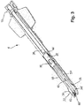
Figur 3 eine perspektivische Unteransicht eines Clip-Magazins, das zu Illustrationszwecken teilweise demontiert ist, -
Figur 4 eine perspektivische Unteransicht eines Teilabschnitts eines Clip-Magazins, das zu Illustrationszwecken teilweise demontiert ist, und -
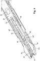
Figur 5 eine perspektivische Seitenansicht eines erfindungsgemäßen Clip-Applikators, der aus einem Handgriffteil und einem daran befestigten Clip-Magazin besteht und zu Illustrationszwecken teilsweise demontiert ist. - Gleiche oder ähnliche Komponenten sind durchgängig mit gleichen Bezugszeichen versehen.
-
Figur 1 zeigt in einer perspektivischen Draufsicht allgemein einen erfindungsgemäßen Clip-Applikator (Clip-Applicator-Set) 1, der aus einem universalen (wiederverwendbaren) Handgriff 2 und einer Anzahl von jeweils einzel auswählbaren, individuellen (einmal verwendbaren) Clip-Magazinen besteht, von denen hier ein einzelnes Clip-Magazin 4 exemplarisch dargestellt ist. Ein solcher Clip-Applikator 1 kann beispielsweise in der offenen und/oder endoskopischen Chirurgie eingesetzt werden, um Gewebestrukturen eines Patienten schnell und zuverlässig miteinander zu verbinden beziehungsweise Blutgefäße eines Patienten schnell und zuverlässig abzuklemmen. - Der Hangriff 2 gemäß nachfolgender detaillierter Beschreibung und das im Wesentlichen schaftförmig ausgebildete Clip-Magazin 4 gemäß nachfolgender detaillierter Beschreibung sind generell jeweils dazu eingerichtet, dass das aus der Vielzahl von Clip-Magazinen bedarfsweise ausgewählte Clip-Magazin 4 an dem Handgriff 2 lösbar befestigt werden kann, um auf diese Weise gemeinsam den Clip-Applikator 1 auszubilden. Aus Illustrationszwecken sind der Handgriff 2 und das Clip-Magazin 4 hier getrennt voneinander dargestellt.
- In jedem Clip-Magazin aus der Vielzahl von schaftförmigen Clip-Magazinen ist eine bestimmte Anzahl von Clips angeordnet beziehungsweise gespeichert / bevorratet. Üblicherweise sind in einem Clip-Magazin etwa fünf bis vierzig Clips, vorzugsweise jedoch 20 bis 30 Clips, angeordnet. Die einzelnen Clip-Magazine aus der Vielzahl von Clip-Magazinen unterscheiden sich untereinander dadurch, dass sie aufgrund ihrer Baugröße beziehungsweise Baulänge eine unterschiedliche Anzahl von Clips aufnehmen können. Weitere Unterscheidungsmerkmale der einzelnen Clip-Magazine untereinander sind auch die Baugröße/Breite, die Bauform (U-förmig oder V-förmig) und die Stärke beziehungsweise Dicke der einzelnen Clips, die in dem jeweiligen Clip-Magazin aufgenommen werden können. Die unterschiedlichen Clip-Magazine aus der Vielzahl von Clip-Magazinen können sich aber auch in ihrer Baulänge, insbesondere ihrer Schaftlänge unterscheiden.
- Die bedarfsweise beziehungsweise bedarfsgerechte Auswahl eines bestimmten Clip-Magazins 4 aus der Vielzahl von Clip-Magazinen zur Befestigung an dem Handgriff 2 kann sich beispielsweise danach richten, welche Gewebestruktur im konkret vorliegenden Fall geklammert beziehungsweise geclipst werden soll, oder beispielsweise auch nach der Größe der abzuklemmenden Blutgefäße des Patienten. Um dem Anwender hierfür eindeutig anzuzeigen, mit welchem Handgriff 2 welches Clip-Magazin 4 verwendet werden kann/darf, weist der Handgriff 2 wenigstens an seiner dem Nutzer zugewandten Oberseite zwei Markierungen 5a und 5b auf, die den Handgriff 2 als ein für bestimmte Clip-Magazine 4 eingerichtetes, bzw. konfiguriertes Hangriffteil kennzeichnen. In diesem Ausführungsbeispiel sind die Markierungen 5a, 5b als kreisförmige, farbige Markierungen ausgebildet, die dem Nutzer/Anwender auf intuitive Weise anzeigen, um welche Ausführungsform des Handgriffteils es sich konkret handelt. In diesem Ausführungsbeispiel handelt es sich bei dem universalen Handgriff 2 um ein eingangs genanntes "Hangrifif-Modell 1" für die zu applizierende Clipgrößen "klein (englisch: small)" und/oder "mittel (englisch: medium)", das dementsprechend durch die zwei farbigen Markierungen 5a, 5b, beispielsweise gelb für "klein (englisch: small)" und blau für "mittel (englisch: medium)" angezeigt wird. Dementsprechend ist ein vorzugsweise aus einem Kunststoff gefertigtes Gehäuse des hierzu passenden Clip-Magazins 4 eingefärbt oder farblich markiert, nämlich in diesem Ausführungsbeispiel in gelber Farbe, um den im Clip-Magazin 4 gespeicherten beziehungsweise bevorrateten Cliptyp als "klein (englisch: small)" zu identifizieren.
- Gemäß der
Figuren 1 und5 weist der Handgriff 2 ein zentrales Gehäuse 2a zur Aufnahme eines Betätigungsgetriebes/Gestänges 54 auf, an dessen distalem Endabschnitt seitlich zwei Griffhebel/Scherengriffe 6 und 8 als Bedienungselemente zur manuellen Betätigung des Clip-Applikators 1 durch einen Anwender, beispielsweise einen Operateur oder Chirurgen, anscharniert sind, derart, dass sich die Griffhebel 6, 8 beidseits am zentralen Gehäuse 2a in Richtung proximal erstrecken. Die Griffhebel 6, 8 sind an ihren proximalen freien Enden jeweils an die Anatomie einer Greifhand des Anwenders konstruktiv angepasst/angenähert. - Des Weiteren weist der Handgriff 2 an seinem (aus Sicht eines Anwenders) distalen Endabschnitt einen mit dem Gehäuse 2a (stoff-) einstückig ausgebildeten oder an diesem befestigten, im Querschnitt U-förmigen Schaft 10 auf, in den eine Crimpauslöse- oder Schließvorrichtung 12 in Form eines längs verschiebbaren, U-förmig ausgebildeten Schiebers und ein Halteteil 14 in Form eines an dem Schaft 10 fixierten (angeschweißten) Bolzens integriert sind, der an einem Längsmittenabschnitt senkrecht vom Grund des U-förmigen Handgriff-Schafts 10 vorragt.
- Die genaue Funktionsweise der Schließvorrichtung 12 und des Halteteils 14 werden nachstehend im Einzelnen erläutert. In
Figur 1 ist jedoch zu erkennen, dass die als U-förmiger Schieber ausgebildete Schließvorrichtung 12 in deren Längsmittenabschnitt eine schlitzförmige Aussparung (Durchbruch) 15 aufweist, durch die der Bolzen 14 hindurchragt, wodurch eine Relativbewegung der Schließvorrichtung (U-förmiger Schieber) 12 gegenüber dem Bolzen 14 in Längsrichtung des Handgriff-Schafts 10 erlaubt wird. - Des Weiteren sind die Länge und die Breite des Schafts 10 des Handgriffs 2 so ausgebildet, dass das im Wesentlichen schaftförmig ausgebildete Clip-Magazin 4 wenigstens teilweise in den Schaft 10 derart eingelegt werden kann, dass der Handgriff 2 und das dazu passend ausgewählte Clip-Magazin 4 im zusammengebauten Zustand eine gesamte Clip-Applikator-Länge von 240 mm bis 340 mm, in diesem Ausführungsbeispiel von 240 mm, ergeben.
- Gemäß der
Fig. 1 und5 ist am Gehäuse 2a des Handgriffs 2 ein von Außen betätigbarer Riegel 18 längsverschiebbar gelagert, der an seinem distalen Randabschnitt vorzugsweise eine Rastnase oder Leiste ausbildet. Der Riegel 18 ist dabei mittels einer inFig. 1 nicht weiter dargestellten Feder 54 (siehe aberFig. 5 ) in Richtung distal in eine Verriegelungsposition vorgespannt. - Das Gehäuse 2a hat an seinen beiden, den Griffhebeln 6, 8 jeweils zugewandten Seiten längsverlaufende Schlitze, in die jeweils zwei Pleuelstäbe (Zug-/Druckstäbe) 56, 58 eingeführt sind, welche die beiden Griffhebel 6, 8 mit dem Betätigungsgetriebe 54 des Handgriffs 2 bzw. mit der Schließvorrichtung 12 koppeln. Das Betätigungsgetriebe 54 besteht vorliegend aus einer relativ zur Schließvorrichtung 12 langsverschiebbar angeordneten, vorzugsweise riegelförmigen Mitnehmereinheit für eine nachfolgend noch beschriebene Clip-Vorschubeinrichtung eines eingesetzten Clip-Magazins 4.
- Diese Mitnehmereinheit 54 hat vorzugsweise ein intern längsverschiebbar gelagertes Eingangselement, an dem jeweils ein Pleuelstab 56 zur Ankopplung beider Griffhebel 6, 8 an das Betätigungsgetriebe 54 angelenkt ist. Das Eingangselement ist über eine interne Rutschkupplung 52 mit einem relativ längsverschiebbar gelagerten Ausgangselement wirkverbunden, das an seinem distalen Ende einen Rast-/Eingreifabschnitt für die Clip-Vorschubeinrichtung des aktuell eingesetzten Clip-Magazins 4 hat. Die das Eingangselement mit den Griffhebeln 6, 8 koppelnden Pleuelstäbe 56 sind dabei ausgehend von den Griffhebeln 6, 8 in Richtung proximal orientiert, derart, dass bei einem scherengriffartigen Zusammendrücken der beiden Griffhebel 6, 8 das Eingangselement und damit über die Rutschkupplung 52 das Ausgangselement in Richtung proximal im Gehäuse 2a verschoben wird.
- Dabei sei darauf hingewiesen, dass die gesamte Mitnehmereinheit 54 gemäß vorstehender Beschreibung über eine Feder am Gehäuse gehalten ist, sodass diese aus der proximalen Position (zusammengedrückte Griffhebel gemäß
Fig. 2 ) in Richtung distale Position (gespreizte Griffhebel gemäßFig. 1 ) elastisch bewegt wird. Ferner sei darauf hingewiesen, dass die Konstruktion der Mitnehmereinheit 54 auch anders ausgestaltet sein kann, solange eine Betätigungskraft, aufgebracht auf die Griffhebel 6, 8 über eine Adaptionsvorrichtung (Überlastungsschutz 50) entsprechend der beispielhaften Eingang-Ausgangselement-Rutschkupplung-Einheit auf den Rast-/Eingriffsabschnitt übertragen wird, um bei Überschreiten einer vorbestimmten Betätigungskraft den Kraftfluss zu unterbrechen und so die Griffhebel 6, 8 leer (kraftfrei) laufen zu lassen. - Beide Griffhebel 6, 8 sind über jeweils einen weiteren Pleuelstab 58 mit der Schließvorrichtung 12 in Form des im Hangriff-Schaft 10 gelagerten U-förmigen Schiebers gekoppelt. Diese beiden weiteren Pleuelstäbe 58 sind gegensätzlich zu den vorstehend genannten Pleuelstäben 56 orientiert, sodass bei einem scherengriffartigen Zusammendrücken der beiden Griffhebel 6, 8 der U-förmige Schieber 12 in Richtung distal verschoben wird.
- Jedes Clip-Magazin 4 gemäß der
Fig. 1 und4 hat einen Schaftabschnitt, der hinsichtlich seiner Abmessungen in den U-förmigen Schaft 10 des Handgriffs 2 eingesetzt werden kann und der auch gleichzeitig den Clipaufnahmeabschnitt (Clipspeicher) des Magazins 4 bildet. Zur lösbaren Befestigung/Arretierung an dem Handgriff 2 weist das im Wesentlichen schaftförmig ausgebildete Clip-Magazin 4 eine Montagevorrichtung 16 am proximalen Ende des Schaftabschnitts auf, die mit dem Riegel (Haltevorrichtung) 18 des Handgriffs 2 zusammenwirkt, um das (teilweise) in den Schaft 10 des Handgriffs 2 eingelegte Clip-Magazin 4 lösbar an dem Handgriff2 zu verriegeln/arretieren. - Am distalen Endschnitt des Schaftabschnitts des Clip-Magazins 4 ist gemäß der
Fig. 3 und4 ein Crimpwerkzeug 22 mit einem Crimpkopf (Maulteil) 20 angeordnet, der in einem mit dem Handgriff 2 zusammengebautem Zustand am distalen Schaftende des Schafts 10 des Handgriffs 2 aus demselben hervorragt. Der Crimpkopf 20 (nachfolgend auch als Maulteil bezeichnet) ist dazu eingerichtet, mit der als U-förmigen Schieber ausgebildeten Schließvorrichtung 12 des Handgriffs 2 zusammenzuwirken, um am distalen Ende des Clip-Applikators 1 gemeinsam das Crimpwerkzeug / Crimpmechanismus 22 des Clip-Applikators 1 auszubilden. - Für das Zusammenwirken mit der als U-förmigen Schieber ausgebildeten Schließvorrichtung 12 weist das Maulteil 20 (in seiner Längsrichtung gesehen) auf der linken und rechten Außenseite jeweils eine (Steuer-) Kulisse 24 und 26 auf. Die Kulissen 24, 26 und die Schließvorrichtung 12 sind jeweils dazu eingerichtet, gemeinsam eine Öffnungs- und Schließbewegung des Maulteils 20 zu definieren. Dabei sind die Position und die geometrische Form der Kulissen 24, 26 des Maulteils 20 für die unterschiedlichen Clip-Magazine aus der Vielzahl von Clip-Magazinen individuell festlegbar/festgelegt, insbesondere in Abhängigkeit des gewählten Clip-Magazins und/oder des zu applizierenden Cliptyps, da je nach Clip-Magazin und/oder Cliptyp eine größere/kleinere Maulöffnung am Crimpkopf 20 notwendig ist.
- Die Öffnungs- und Schließbewegung des Crimpkopfs/Maulteils 20 ergibt sich, wenn die als U-förmiger Schieber ausgebildete Schließvorrichtung 12 bei deren Längsbewegung im Handgriff-Schaft 10 die Kulissen 24, 26 des Maulteils 20 wenigstens teilweise außenseitig umgreift, so dass zwei (in
Figur 2 nicht gezeigte) Innenflächen der U-förmigen Schließvorrichtung 12 in Kontakt mit den Kulissen 24, 26 gelangen und damit auch die Öffnungs- und Schließbewegung des Maulteils 20 festlegen beziehungsweise steuern. Hierzu sind das Maulteil 20 und die Schließvorrichtung 12 jeweils dazu eingerichtet beziehungsweise konfiguriert, dass die als U-förmiger Schieber ausgebildete Schließvorrichtung 12 das mittels des Halteteils (Bolzens) 14 in Längsrichtung des Schafts 10 fixierte Maulteil 20 wenigstens teilweise umgreift, wenn die beiden Griffhebel 6 und 8 manuell betätigt (zusammen gedrückt) werden. Das heißt, dass die Schließvorrichtung 12 bei einer Betätigung der Griffhebel 6, 8 durch die vorstehend angedeuteten Pleuelstäbe 56, 58 des Handgriffs 2 längs in distaler Richtung des Clip-Applikators 1 so weit nach vorne in Richtung distal bewegt beziehungsweise geschoben wird, bis die Schließvorrichtung 12 die Kulissen 24, 26 des Maulteils 20 umgreift und dadurch das Maulteil 20 in eine Schließbewegung zwingt. Durch diese Bewegung der Schließvorrichtung 12, die durch die Position und/oder Form der Kulissen 24, 26 festgelegt beziehungsweise gesteuert wird, wird das Maulteil 20 geschlossen und nach erfolgter Betätigung der Griffhebel 6, 8 beziehungsweise durch ein Loslassen derselben wieder geöffnet. Die Öffnungsbewegung ergibt sich dabei durch eine (aus distaler Sicht) Rückwärtsbewegung der als U-förmigen Schieber ausgebildeten Schließvorrichtung 12. -
Figur 3 zeigt eine perspektivische Unteransicht des Clip-Magazins 4, das zu Illustrationszwecken teilweise demontiert ist, beziehungsweise von dem einzelne Bauteile zur anschaulicheren Beschreibung entfernt sind. - In
Figur 3 ist zu erkennen, dass das Crimpwerkzeug 22 im Wesentlichen gabelförmig ausgebildet ist und zwei zueinander parallele Branchen 28 und 30 aufweist. An den in distale Richtung weisenden freien Enden des Crimpwerkzeugs 22 weist dasselbe zwei einstückig angeformte Maulteilbacken 32 und 34 auf, an denen die oben beschriebenen Kulissen 24, 26 angeordnet/ausgebildet sind und welche das Maulteil (Crimpkopf) 20 bilden. Es ist ebenfalls zu erkennen, dass das Crimpwerkzeug 22 an seinem proximalen Ende eine Ausnehmung 36 als Befestigungsöffnung zum ineinandergreifenden Zusammenwirken mit dem Halteteil (Bolzen) 14 des Handgriffs 2 aufweist. Die Ausnehmung 36 ist in diesem Ausführungsbeispiel als Langloch ausgebildet, in das im zusammengesetzten Zustand das Halteteil 14 des Handgriffs 2 eingreift, um das in den Schaft 10 eingeclipste Crimpwerkzeug 22 derart sicher an dem Schaft 10 zu fixieren, dass es sich nicht in Längsrichtung des Clip-Magazins 4 beziehungsweise in Längsrichtung des Schafts 10 des Handgriffteils 2 bewegen kann. In anderen Worten ist die Längsposition des Crimpwerkzeugs 22 und damit des Maulteils 20 durch das Zusammenwirken der Ausnehmung 36 mit dem Halteteil 14 festgelegt, so dass es sich weder relativ zum Schaft 10 des Handgriffs 2, noch relativ zu anderen Bauteilen des Clip-Magazins 4 bewegen kann. - Das in
Figur 3 dargestellte Clip-Magazin 4 weist auch eine Clip-Vorschubeinrichtung 38 in Form einer Clip-Vorschubstange zum Aufnehmen und Zustellen, das bedeutet Transportieren, von vereinzelten Clips auf. Die Clip-Vorschubeinrichtung 38 ist für ein Zusammenwirken mit dem Maulteil 20 eingerichtet und ist relativ zu diesem in Längsrichtung des Clip-Magazins 4 beziehungsweise in Längsrichtung des Schafts 10 des Handgriffs 2 verschiebbar gelagert. Das heißt, dass die Vorschubeinrichtung 38 die Funktion aufweist, einzelne Clips aus dem Clip-Magazin 4 aufzunehmen und diese in distaler Längsrichtung des Schafts 10 weiter zu transportieren. Hierfür weist die Clip-Vorschubeinrichtung 38 an seinem distalen Ende eine Clipzunge 40 auf, mit der einzelne Clips aufnehmbar und zustellbar beziehungsweise transportierbar sind. - Für die Aufnahme der einzelnen Clips aus dem Clip-Magazin 4 ist eine (aus distaler Sicht) Rückwärtsbewegung der Clip-Vorschubeinrichtung 38 notwendig, da die einzelnen Clips (aus distaler Sicht) hinter den Maulteilbacken 32, 34 zur Bevorratung positioniert sind. Aus diesem Grund muss die Clip-Vorschubeinrichtung 38 eine Rückwärtsbewegung ausführen, damit diese (aus distaler Sicht) hinter genau dem Clip positioniert wird, der als nächstes aufgenommen und in Längsrichtung des Schafts 10 nach vorne in Richtung hin zum Maulteil 20 zugestellt beziehungsweise transportiert werden soll. Dagegen ist für die Zustellung beziehungsweise den Transport des mittels der Clip-Vorschubeinrichtung 38 aufgenommen Clips eine (aus proximaler Sicht) Vorwärtsbewegung notwendig, um den aufgenommen Clip in Richtung hin zum Maulteil 20, das heißt entlang der Branchen 28, 30 des Crimpwerkzeugs 22 zwischen die Maulteilbacken 32, 34 desselben zu bewegen.
- Um diese beiden Längsbewegungen der Clip-Vorschubeinrichtung 38, nämlich (aus proximaler Sicht) nach vorne hin zum Maulteil 20 und (aus proximaler Sicht) nach hinten hin zum Clipaufnahmeabschnitt (Clipspeicher) auf einfache Weise zu begrenzen, weist die Clip-Vorschubeinrichtung 38 zwei in Längsrichtung derselben voneinander beabstandete Begrenzungsanschläge 42 und 44 auf. Die Begrenzungsanschläge 42, 44 sind so ausgeformt und bemessen, dass sie jeweils mit dem Crimpwerkzeug 22 in
- Kontakt kommen können, dessen Längsposition gegenüber der Clip-Vorschubeinrichtung 38 mittels des in die Ausnehmung 36 eingreifenden Halteteils 14 festgelegt ist. Das heißt, dass die am Crimpwerkzeug 22 situationsabhängig anschlagenden Begrenzungsanschläge 42, 44 die Längsbewegung der Clip-Vorschubeinrichtung 38 in beide Längsrichtungen begrenzen.
- In diesem Ausführungsbeispiel sind die Begrenzungsanschläge 42, 44 als Stanz-/Biegeteil einstückig mit der Clip-Vorschubeinrichtung 38 ausgebildet. Der Abstand in Längsrichtung zwischen den beiden Begrenzungsanschlägen 42, 44 ist so bemessen beziehungsweise gewählt und festgelegt, dass die Clipzunge 40 bei einer (aus proximaler Sicht) Rückwärtsbewegung der Clip-Vorschubeinrichtung 38, das heißt bei einer Clip-Aufnahmebewegung der Clip-Vorschubreinrichtung 38, genau ein einziger Clip aus dem Clip-Magazin 4 aufgenommen wird, wie dies nachfolgend noch näher erläutert wird. In
Figur 3 ist die Clip-Vorschubeinrichtung 38 in einer Lage/Position dargestellt, in der der proximale, das heißt der in Clip-Vorschubrichtung hintere Begrenzungsanschlag 44 mit dem Crimpwerkzeug 22 in anliegenden Kontakt ist. GemäßFigur 3 ist die Clip-Vorschubeinrichtung 38 folglich in einer Lage/Position dargestellt, in der ein einzelner Clip 46 mittels der Clipzunge 40 der Clip-Vorschubeinrichtung 38 hin zum distalen Ende des Maulteils 20, das heißt in das Crimpzeug 22 hinein transportiert wurde beziehungsweise in diesem angeordnet ist. - Es ist offensichtlich, dass die in
Figur 3 dargestellte Position der Clip-Vorschubeinrichtung 38 (noch) keine Position ist, in der sich die Backen 32, 34 des Maulteils 20 zum Vercrimpen des eingeführten Clip schließen können. Denn für das Schließen der Maulteilbacken 32, 34 ist vorab eine Rückwärtsbewegung der Clip-Vorschubeinrichtung 38 notwendig, damit diese nicht in der gezeigten Lage vollständig zwischen den Maulteilbacken 32, 34 angeordnet bleibt. - In
Figur 4 , die eine perspektivische Unteransicht eines Teilabschnitts des Clip-Magazins 4 in einem teilweise demontierten Zustand zeigt, ist die Clip-Vorschubeinrichtung 38 in einer anderen Lage/Position dargestellt, in der es den einzelnen Clip 46 aus einem Clipspeicherabschnitt 48 des Clip-Magazins 4 zum Zustellen beziehungsweise Weitertransport in Richtung hin zum Maulteil 20 (Crimpwerkzeug 22) aufnehmen kann. Es ist zu erkennen, dass der Clipspeicherabschnitt 48 (aus distaler Sicht) hinter den Maulteilbacken 32, 34 angeordnet ist, so dass ein einzelner Clip 46 (aus distaler Sicht) nach vorne zugestellt beziehungsweise transportiert werden muss, um ihn zwischen die Maulteilbacken 32, 34 zu fördern. - Weiter ist in
Figur 4 zu erkennen, dass die Clip-Vorschubeinrichtung 38 in der dargestellten Clip-Aufnahmeposition mit dem distalen, das heißt mit dem in Clip-Vorschubrichtung vorderen Begrenzungsanschlag 42 an dem Crimpwerkzeug 22 anliegt, wodurch die Clip-Aufnahmebewegung in dieser Bewegungsrichtung begrenzt wird. Durch die in Abhängigkeit des Clip-Magazins 4 bemessene und entsprechend festgelegte Positionierung des Begrenzungsanschlags 42 ist sichergestellt, dass gleichzeitig immer nur ein einziger Clip 46 aus dem Clipspeicher 48 des Clip-Magazins 4 aufgenommen wird und dieser in einer anschließenden Clip-Zustellbewegung in Clip-Vorschubrichtung hin zum distalen Ende des Crimpwerkzeugs 22, das heißt zwischen die Maulteilbacken 32, 34 beziehungsweise in das Maulteil 20 hinein transportiert wird. - In
Figur 5 , die eine perspektivische Seitenansicht des Clip-Applikators 1 in einem teilweise demontierten Zustand zeigt, ist zu erkennen, dass der Handgriff 2 des Clip-Applikators 1 den integrierten Überlastungsschutz 50 mit Rutschkupplung 52 aufweist. Der Überlastschutz 50 mit Rutschkupplung 52) verhindert bei einem Anschlag des vorderen Begrenzungsanschlags 42 an dem Crimpwerkzeug 22, dass die Mechanik des Handgriffs 2 und/oder die Mechanik beziehungsweise Gehäuseteile des Clip-Magazins 4, oder auch der Begrenzungsanschlag 42 selbst beziehungsweise das Maulteil 20, durch zu hohe Betätigungskräfte des Anwenders beschädigt werden. Da die Abstände zwischen den Begrenzungsanschlägen 42, 44 des Clip-Magazins 4 für die unterschiedlichen Clip-Magazine aus der Vielzahl von Clip-Magazinen unterschiedlich positioniert beziehungsweise festgelegt sind, kann durch den Überlastungsschutz 50 zusätzlich sichergestellt werden, dass ein universaler Handgriff 2 mit mehreren aus der Vielzahl von Clip-Magazinen zusammenwirken kann, ohne die Mechanik oder die - Bauteile des jeweiligen Handgriffs 2 und/oder des jeweiligen Clip-Magazins 4 infolge zu hoher manueller Betätigungskräfte zu beschädigen.
- Der Betrieb beziehungsweise der praktische Gebrauch des Clip-Applikators 1 kann wie nachfolgend beschrieben ablaufen.
-
Figur 2 zeigt in einer perspektivischen Seitenansicht den Clip-Applikator 1 im zusammengebauten, das heißt im funktionstüchtigen Zustand, in dem das Clip-Magazin 4 durch das Zusammenwirken der Montagevorrichtung 16 und der Haltevorrichtung 18 aneinander befestigt sind. - Nach der Montage des Clip-Applikators 1 durch das Befestigen des bedarfsweise ausgewählten Clip-Magazins 4 an dem universalen Handgriff 2, befindet sich der Clip-Applikator 1 in einem funktionstüchtigen Zustand. D.h. in diesem Zustand ist das Clip-Magazin 4 in den Handgriff-Schaft 10 eingesetzt und wird vom Riegel 18 arretiert.
- Durch eine manuelle Betätigung der zwei Griffhebel 6 und 8 des Handgriffs 2 wird die interne Betätigungsmechanik 54 des Handgriffs 2 so aktiviert, dass die als U-förmiger Schieber ausgebildete Schließvorrichtung 12 in distale Richtung längsverschoben wird. Bedingt durch diese Längsverschiebung der Schließvorrichtung 12 wird diese über die Kulissen 24, 26 des Maulteils 20 geschoben, wodurch dessen Maulteilbacken 32, 34 aufeinander zu, d.h. nach innen gedrückt werden und somit das Crimpwerkzeug 22 geschlossen wird.
- Andererseits (gleichzeitig) wird die interne Betätigungsmechanik 54 des Handgriffs 2 auch so betätigt, dass die Clip-Vorschubeinrichtung 38 in einer der Schließvorrichtung 12 gegenläufigen Längsbewegung (in Richtung proximal) solange verschoben wird, bis der vordere Begrenzungsanschlag 42 am fixierten Crimpwerkzeug 22 anschlägt und gegebenenfalls die Rutschkupplung 52 des Überlastungsschutzes 50 ausgelöst wird. Die interne Betätigungsmechanik 54 des Handgriffs 2 hält die Clip-Vorschubeinrichtung 38 dann solange in dieser Position fest, bis die Maulteilbacken 32, 34 durch ein Zurückverschieben der Schließvorrichtung 12 wieder voneinander beabstandet warden und somit das Crimpwerkzeug 22 wieder geöffnet wird. Somit ist nun wieder ein Freiraum zwischen den Maulteilbacken 32, 34 geschaffen, wobei die Clip-Vorschubeinrichtung 38 mittels der internen Betätigungsmechanik 54 (automatisch) freigegeben wird und durch eine feder-vorgespannt unterstützte Vorwärtsbewegung der nächste Clip durch die Clipzunge 40 zwischen Maulteilbacken 32, 34 transportiert werden kann.
- Zusammenfassend wird ein chirurgischer Clip-Applikator offenbart, mit einem Universal-Handgriff und mit einem Individual-Clipmagazin mit integrietem Crimpkopf/Crimpwerkzeug, das an dem Universal-Handgriff lösbar befestigbar ist. Der Universal-Handgriff und das daran befestigte Individual-Clipmagazin wirken zusammen, um einen zur Betätigung festgelegten bzw. individuell zur Verfügung stehenden Zustellweg für den Cliptransport einzelner Clips aus einem Clip-Aufnahmeabschnitt des Clip-Magazins hin zum Crimpkopf auszubilden. Erfindungsgemäß ist das Individual-Clipmagazin aus einer Vielzahl von Clip-Magazinen für unterschiedliche Cliptypen bedarfsweise auswählbar, wobei das Clip-Magazin eine integrierte und in Abhängigkeit des zu applizierenden Cliptyps ausgebildete Kodiermechanik aufweist, die im Zusammenwirken mit den Universal-Handgriff wenigstens den an den jeweiligen Cliptyp angepassten Zustellweg festlegt.
Claims (12)
- Universalhandgriff eines chirurgischen Clip-Applikators (1), an dem ein einen Crimpkopf/Crimpwerkzeug (20, 22) aufweisendes, aus einer Anzahl von unterschiedlichen Clipmagazinen beliebig auswählbares Individual-Clipmagazin (4) montier- oder befestigbar ist, derart, dass der Universalhandgriff (2) und das daran befestigte Individual-Clipmagazin (4) zum Vercrimpen einzelner Clips (46) im Crimpkopf/Crimpwerkzeug (20, 22) sowie zum Fördern einzelner Clips aus einem Clip-Aufnahmeabschnitt (48) über einen individuellen Zustellweg hin zum Crimpkopf/Crimpwerkzeug (20, 22) mechanisch zusammenwirken, wofür der Universalhandgriff (2) ein integriertes Kraftübertragungsgetriebe (54) mit wenigstens einer manuell ergreifbaren Handhabe (6, 8) als Betätigungs-Eingangsteil und mit einer Kopplung als Betätigungs-Abgabeteil zum Individual-Clipmagazin (4) hat,
gekennzeichnet durch eine Adaptionsvorrichtung (50, 52) mit einem Überlastungsschutz (50), der zwischen Betätigungs-Eingangsteil und Betätigungs-Abgabeteil für ein Unterbrechen der Kraftübertragung im Kraftübertragungsgetriebe (54) angeordnet ist, wenn die Förderung einzelner Clips aus dem Clipmagazin (4) durch zumindest einen Begrenzungsanschlag (42, 44) begrenzt ist, zur Kompensation/Anpassung von Clip-bedingten Unterschieden zwischen dem individuellen Zustellweg des aktuell befestigten Individual-Clipmagazins (4) und einem maximalen Betätigungsweg des Betätigungs-Eingangsteils am Universalhandgriff (2). - Universalhandgriff nach Anspruch 1, dadurch gekennzeichnet, dass die Adaptionsvorrichtung (50, 52) dafür ausgebildet ist, dass der an den jeweiligen Cliptyp angepasste Zustellweg durch eine in dem aktuell befestigten Individual-Clipmagazin (4) integrierte sowie in Abhängigkeit des zu applizierenden Cliptyps ausgebildete Kodiermechanik (20, 24, 26, 38, 42, 44) festgelegt wird oder ist.
- Universalhandgriff nach Anspruch 1 oder 2, dadurch gekennzeichnet, dass der Überlastungsschutz (50) eine Rutschkupplung (52) oder einen Ausklinkmechanismus aufweist.
- Universalhandgriff nach Anspruch 3, dadurch gekennzeichnet, dass die Rutschkupplung (52) auf einen Durchrutschwert oberhalb der für die Förderung einzelner Clips aus dem Clipaufnahmespeicher (48) über den individuellen Zustellweg hin zum Crimpkopf/Crimpwerkzeug (20, 22) erforderlichen Kraft sowie unterhalb einer vorbestimmten, das Kraftübertragungsgetriebe (54) überbelastenden Betätigungskraft eingestellt ist.
- Chirurgischer Clip-Applikator (1), gekennzeichnet durcheinen Universal-Handgriff (2) gemäß einem der Ansprüche 1 bis 4 undein separat dazu und zur Montage an dem Universalhandgriff (2) ausgebildeten Individual-Clipmagazin (4), welcheseinen Crimpkopf /Crimpwerkzeug (20, 22),einen Clip-Aufnahmeabschnitt (48) undeine Clip-Vorschubeinrichtung (38) zum Fördern einzelner Clips aus dem Clip-Aufnahmeabschnitt (48) über einen individuellen Zustellweg hin zum Crimpkopf/Crimpwerkzeug (20, 22) in Abhängigkeit einer manuellen Betätigung des Universalhandgriffs (2) aufweist, wobei die Clip-Vorschubeinrichtung (38) dafür angepasst ist, um mit einem Rast-/Eingreifabschnitt am distalen Ende des Betätigungs-Abgabeteils/Ausgangselements an der Adaptionsvorrichtung (52) des Universalhandgriffs zusammen zu wirken, und wobeidas aus einer Vielzahl von Clipmagazinen für unterschiedliche Cliptypen bedarfsweise auswählbare Individual-Clipmagazin (4) eine integrierte und in Abhängigkeit des zu applizierenden Cliptyps ausgebildete Kodiermechanik (20, 24, 26, 38, 42, 44) mit zwei Begrenzungsanschlägen (42, 44) zur wenigstens teilweisen Festlegung des an den jeweiligen Cliptyp angepassten, individuellen Zustellwegs aufweist, um die Bewegung der Clip-Vorschubeinrichtung (38) in ihre beiden Längsrichtungen zu begrenzen.
- Chirurgischer Clip-Applikator (1) nach Anspruch 5, dadurch gekennzeichnet, dass die Kodiermechanik zwei in Längs-/Bewegungsrichtung der Clip-Vorschubeinrichtung voneinander beabstandete Begrenzungsanschläge (42, 44) aufweist, deren Positionen in Abhängigkeit des zu applizierenden Cliptyps derart angepasst sind, dass durch eine Rückwärts- und/oder Vorwärtsbewegung der Vorschubeinrichtung (38) jeweils genau ein Clip aus dem Clip-Magazin (4) hin zum Crimpkopf/Crimpwerkzeug (20, 22) transportierbar ist.
- Chirurgischer Clip-Applikator (1) nach Anspruch 5 oder 6, dadurch gekennzeichnet, dass die Clip-Vorschubeinrichtung (38) ein längsbeweglich gehaltener Stab vorzugsweise in Form einer Platte ist, wobei weiter vorzugsweise der wenigstens eine Begrenzungsanschlag (42, 44) als ein Schnitt- und/oder Biegeteil in den Stab integriert ist.
- Chirurgischer Clip-Applikator (1) nach Anspruch 5 oder 6, dadurch gekennzeichnet, dass der Crimpkopf/Crimpwerkzeug (20, 22) angepasst ist, um mit dem wenigstens einen Begrenzungsanschlag (42, 44) der Clip-Vorschubeinrichtung (38) in Kontakt zu kommen, um eine Rückwärts- und/oder Vorwärtsbewegung der Clip-Vorschubeinrichtung (38) zu begrenzen.
- Chirurgischer Clip-Applikator (1) nach einem der Ansprüche 5 bis 8, dadurch gekennzeichnet, dass der Universal-Handgriff (2) als ein wiederverwendbares Teil ausgebildet ist.
- Chirurgischer Clip-Applikator (1) nach einem der Ansprüche 5 bis 9, dadurch gekennzeichnet, dass das Individual-Clipmagazin (4) als ein Einweg-Teil ausgebildet ist.
- Chirurgischer Clip-Applikator (1) nach einem der vorangehenden Ansprüche 5 bis 10, dadurch gekennzeichnet, dass der Universal-Handgriff (2) und das Individual-Clipmagazin (4) eine an den zu applizierenden Cliptyp angepasste Farb- und/oder Symbolkodierung (5a, 5b) zur Visualisierung des mit dem Universal-Handgriff (2) aktuell verwendeten Individual-Clipmagazins (4) aufweist.
- Chirurgischer Clip-Applikator (1) nach einem der vorangehenden Ansprüche 5 bis 11, dadurch gekennzeichnet, dass der Crimpkopf /Crimpwerkzeug (20, 22) eine das Schließen und Öffnen steuernde Kulisse aufweist, deren Position und/oder Geometrie an den zu applizierenden Cliptyp und/oder an die Schaftlänge des Clip-Magazins (4) angepasst ist.
Applications Claiming Priority (2)
| Application Number | Priority Date | Filing Date | Title |
|---|---|---|---|
| DE102013106277.6A DE102013106277A1 (de) | 2013-06-17 | 2013-06-17 | Chirurgischer Clip-Applikator |
| PCT/EP2014/062193 WO2014202449A2 (de) | 2013-06-17 | 2014-06-12 | Chirurgischer clip-applikator |
Publications (2)
| Publication Number | Publication Date |
|---|---|
| EP3010425A2 EP3010425A2 (de) | 2016-04-27 |
| EP3010425B1 true EP3010425B1 (de) | 2021-12-08 |
Family
ID=50981490
Family Applications (1)
| Application Number | Title | Priority Date | Filing Date |
|---|---|---|---|
| EP14732127.7A Active EP3010425B1 (de) | 2013-06-17 | 2014-06-12 | Chirurgischer clip-applikator |
Country Status (7)
| Country | Link |
|---|---|
| US (1) | US10390830B2 (de) |
| EP (1) | EP3010425B1 (de) |
| JP (2) | JP2016523617A (de) |
| CN (1) | CN105555206B (de) |
| DE (1) | DE102013106277A1 (de) |
| ES (1) | ES2907256T3 (de) |
| WO (1) | WO2014202449A2 (de) |
Families Citing this family (395)
| Publication number | Priority date | Publication date | Assignee | Title |
|---|---|---|---|---|
| US9060770B2 (en) | 2003-05-20 | 2015-06-23 | Ethicon Endo-Surgery, Inc. | Robotically-driven surgical instrument with E-beam driver |
| US20070084897A1 (en) | 2003-05-20 | 2007-04-19 | Shelton Frederick E Iv | Articulating surgical stapling instrument incorporating a two-piece e-beam firing mechanism |
| US9072535B2 (en) | 2011-05-27 | 2015-07-07 | Ethicon Endo-Surgery, Inc. | Surgical stapling instruments with rotatable staple deployment arrangements |
| US11896225B2 (en) | 2004-07-28 | 2024-02-13 | Cilag Gmbh International | Staple cartridge comprising a pan |
| US11998198B2 (en) | 2004-07-28 | 2024-06-04 | Cilag Gmbh International | Surgical stapling instrument incorporating a two-piece E-beam firing mechanism |
| US8215531B2 (en) | 2004-07-28 | 2012-07-10 | Ethicon Endo-Surgery, Inc. | Surgical stapling instrument having a medical substance dispenser |
| US11246590B2 (en) | 2005-08-31 | 2022-02-15 | Cilag Gmbh International | Staple cartridge including staple drivers having different unfired heights |
| US7669746B2 (en) | 2005-08-31 | 2010-03-02 | Ethicon Endo-Surgery, Inc. | Staple cartridges for forming staples having differing formed staple heights |
| US9237891B2 (en) | 2005-08-31 | 2016-01-19 | Ethicon Endo-Surgery, Inc. | Robotically-controlled surgical stapling devices that produce formed staples having different lengths |
| US7934630B2 (en) | 2005-08-31 | 2011-05-03 | Ethicon Endo-Surgery, Inc. | Staple cartridges for forming staples having differing formed staple heights |
| US10159482B2 (en) | 2005-08-31 | 2018-12-25 | Ethicon Llc | Fastener cartridge assembly comprising a fixed anvil and different staple heights |
| US11484312B2 (en) | 2005-08-31 | 2022-11-01 | Cilag Gmbh International | Staple cartridge comprising a staple driver arrangement |
| US20070106317A1 (en) | 2005-11-09 | 2007-05-10 | Shelton Frederick E Iv | Hydraulically and electrically actuated articulation joints for surgical instruments |
| US7845537B2 (en) | 2006-01-31 | 2010-12-07 | Ethicon Endo-Surgery, Inc. | Surgical instrument having recording capabilities |
| US11224427B2 (en) | 2006-01-31 | 2022-01-18 | Cilag Gmbh International | Surgical stapling system including a console and retraction assembly |
| US20120292367A1 (en) | 2006-01-31 | 2012-11-22 | Ethicon Endo-Surgery, Inc. | Robotically-controlled end effector |
| US11278279B2 (en) | 2006-01-31 | 2022-03-22 | Cilag Gmbh International | Surgical instrument assembly |
| US8708213B2 (en) | 2006-01-31 | 2014-04-29 | Ethicon Endo-Surgery, Inc. | Surgical instrument having a feedback system |
| US20110024477A1 (en) | 2009-02-06 | 2011-02-03 | Hall Steven G | Driven Surgical Stapler Improvements |
| US7753904B2 (en) | 2006-01-31 | 2010-07-13 | Ethicon Endo-Surgery, Inc. | Endoscopic surgical instrument with a handle that can articulate with respect to the shaft |
| US11793518B2 (en) | 2006-01-31 | 2023-10-24 | Cilag Gmbh International | Powered surgical instruments with firing system lockout arrangements |
| US8186555B2 (en) | 2006-01-31 | 2012-05-29 | Ethicon Endo-Surgery, Inc. | Motor-driven surgical cutting and fastening instrument with mechanical closure system |
| US20110290856A1 (en) | 2006-01-31 | 2011-12-01 | Ethicon Endo-Surgery, Inc. | Robotically-controlled surgical instrument with force-feedback capabilities |
| US8820603B2 (en) | 2006-01-31 | 2014-09-02 | Ethicon Endo-Surgery, Inc. | Accessing data stored in a memory of a surgical instrument |
| US8992422B2 (en) | 2006-03-23 | 2015-03-31 | Ethicon Endo-Surgery, Inc. | Robotically-controlled endoscopic accessory channel |
| US8322455B2 (en) | 2006-06-27 | 2012-12-04 | Ethicon Endo-Surgery, Inc. | Manually driven surgical cutting and fastening instrument |
| US10568652B2 (en) | 2006-09-29 | 2020-02-25 | Ethicon Llc | Surgical staples having attached drivers of different heights and stapling instruments for deploying the same |
| US11980366B2 (en) | 2006-10-03 | 2024-05-14 | Cilag Gmbh International | Surgical instrument |
| US11291441B2 (en) | 2007-01-10 | 2022-04-05 | Cilag Gmbh International | Surgical instrument with wireless communication between control unit and remote sensor |
| US8840603B2 (en) | 2007-01-10 | 2014-09-23 | Ethicon Endo-Surgery, Inc. | Surgical instrument with wireless communication between control unit and sensor transponders |
| US8684253B2 (en) | 2007-01-10 | 2014-04-01 | Ethicon Endo-Surgery, Inc. | Surgical instrument with wireless communication between a control unit of a robotic system and remote sensor |
| US11039836B2 (en) | 2007-01-11 | 2021-06-22 | Cilag Gmbh International | Staple cartridge for use with a surgical stapling instrument |
| US20080169333A1 (en) | 2007-01-11 | 2008-07-17 | Shelton Frederick E | Surgical stapler end effector with tapered distal end |
| US7438209B1 (en) | 2007-03-15 | 2008-10-21 | Ethicon Endo-Surgery, Inc. | Surgical stapling instruments having a releasable staple-forming pocket |
| US8931682B2 (en) | 2007-06-04 | 2015-01-13 | Ethicon Endo-Surgery, Inc. | Robotically-controlled shaft based rotary drive systems for surgical instruments |
| US11857181B2 (en) | 2007-06-04 | 2024-01-02 | Cilag Gmbh International | Robotically-controlled shaft based rotary drive systems for surgical instruments |
| US7753245B2 (en) | 2007-06-22 | 2010-07-13 | Ethicon Endo-Surgery, Inc. | Surgical stapling instruments |
| US11849941B2 (en) | 2007-06-29 | 2023-12-26 | Cilag Gmbh International | Staple cartridge having staple cavities extending at a transverse angle relative to a longitudinal cartridge axis |
| US8636736B2 (en) | 2008-02-14 | 2014-01-28 | Ethicon Endo-Surgery, Inc. | Motorized surgical cutting and fastening instrument |
| US7866527B2 (en) | 2008-02-14 | 2011-01-11 | Ethicon Endo-Surgery, Inc. | Surgical stapling apparatus with interlockable firing system |
| US9179912B2 (en) | 2008-02-14 | 2015-11-10 | Ethicon Endo-Surgery, Inc. | Robotically-controlled motorized surgical cutting and fastening instrument |
| US8573465B2 (en) | 2008-02-14 | 2013-11-05 | Ethicon Endo-Surgery, Inc. | Robotically-controlled surgical end effector system with rotary actuated closure systems |
| US11986183B2 (en) | 2008-02-14 | 2024-05-21 | Cilag Gmbh International | Surgical cutting and fastening instrument comprising a plurality of sensors to measure an electrical parameter |
| US8758391B2 (en) | 2008-02-14 | 2014-06-24 | Ethicon Endo-Surgery, Inc. | Interchangeable tools for surgical instruments |
| US7819298B2 (en) | 2008-02-14 | 2010-10-26 | Ethicon Endo-Surgery, Inc. | Surgical stapling apparatus with control features operable with one hand |
| JP5410110B2 (ja) | 2008-02-14 | 2014-02-05 | エシコン・エンド−サージェリィ・インコーポレイテッド | Rf電極を有する外科用切断・固定器具 |
| US10390823B2 (en) | 2008-02-15 | 2019-08-27 | Ethicon Llc | End effector comprising an adjunct |
| US11648005B2 (en) | 2008-09-23 | 2023-05-16 | Cilag Gmbh International | Robotically-controlled motorized surgical instrument with an end effector |
| US9005230B2 (en) | 2008-09-23 | 2015-04-14 | Ethicon Endo-Surgery, Inc. | Motorized surgical instrument |
| US9386983B2 (en) | 2008-09-23 | 2016-07-12 | Ethicon Endo-Surgery, Llc | Robotically-controlled motorized surgical instrument |
| US8210411B2 (en) | 2008-09-23 | 2012-07-03 | Ethicon Endo-Surgery, Inc. | Motor-driven surgical cutting instrument |
| US8608045B2 (en) | 2008-10-10 | 2013-12-17 | Ethicon Endo-Sugery, Inc. | Powered surgical cutting and stapling apparatus with manually retractable firing system |
| US8517239B2 (en) | 2009-02-05 | 2013-08-27 | Ethicon Endo-Surgery, Inc. | Surgical stapling instrument comprising a magnetic element driver |
| JP2012517287A (ja) | 2009-02-06 | 2012-08-02 | エシコン・エンド−サージェリィ・インコーポレイテッド | 被駆動式手術用ステープラの改良 |
| US8220688B2 (en) | 2009-12-24 | 2012-07-17 | Ethicon Endo-Surgery, Inc. | Motor-driven surgical cutting instrument with electric actuator directional control assembly |
| US8851354B2 (en) | 2009-12-24 | 2014-10-07 | Ethicon Endo-Surgery, Inc. | Surgical cutting instrument that analyzes tissue thickness |
| US8783543B2 (en) | 2010-07-30 | 2014-07-22 | Ethicon Endo-Surgery, Inc. | Tissue acquisition arrangements and methods for surgical stapling devices |
| US11812965B2 (en) | 2010-09-30 | 2023-11-14 | Cilag Gmbh International | Layer of material for a surgical end effector |
| US9241714B2 (en) | 2011-04-29 | 2016-01-26 | Ethicon Endo-Surgery, Inc. | Tissue thickness compensator and method for making the same |
| US9629814B2 (en) | 2010-09-30 | 2017-04-25 | Ethicon Endo-Surgery, Llc | Tissue thickness compensator configured to redistribute compressive forces |
| US9272406B2 (en) | 2010-09-30 | 2016-03-01 | Ethicon Endo-Surgery, Llc | Fastener cartridge comprising a cutting member for releasing a tissue thickness compensator |
| US11925354B2 (en) | 2010-09-30 | 2024-03-12 | Cilag Gmbh International | Staple cartridge comprising staples positioned within a compressible portion thereof |
| US9386988B2 (en) | 2010-09-30 | 2016-07-12 | Ethicon End-Surgery, LLC | Retainer assembly including a tissue thickness compensator |
| US11298125B2 (en) | 2010-09-30 | 2022-04-12 | Cilag Gmbh International | Tissue stapler having a thickness compensator |
| US20120080336A1 (en) | 2010-09-30 | 2012-04-05 | Ethicon Endo-Surgery, Inc. | Staple cartridge comprising staples positioned within a compressible portion thereof |
| US10945731B2 (en) | 2010-09-30 | 2021-03-16 | Ethicon Llc | Tissue thickness compensator comprising controlled release and expansion |
| US12213666B2 (en) | 2010-09-30 | 2025-02-04 | Cilag Gmbh International | Tissue thickness compensator comprising layers |
| US8695866B2 (en) | 2010-10-01 | 2014-04-15 | Ethicon Endo-Surgery, Inc. | Surgical instrument having a power control circuit |
| CN104053407B (zh) | 2011-04-29 | 2016-10-26 | 伊西康内外科公司 | 包括定位在其可压缩部分内的钉的钉仓 |
| US11207064B2 (en) | 2011-05-27 | 2021-12-28 | Cilag Gmbh International | Automated end effector component reloading system for use with a robotic system |
| US9044230B2 (en) | 2012-02-13 | 2015-06-02 | Ethicon Endo-Surgery, Inc. | Surgical cutting and fastening instrument with apparatus for determining cartridge and firing motion status |
| BR112014024098B1 (pt) | 2012-03-28 | 2021-05-25 | Ethicon Endo-Surgery, Inc. | cartucho de grampos |
| MX353040B (es) | 2012-03-28 | 2017-12-18 | Ethicon Endo Surgery Inc | Unidad retenedora que incluye un compensador de grosor de tejido. |
| MX358135B (es) | 2012-03-28 | 2018-08-06 | Ethicon Endo Surgery Inc | Compensador de grosor de tejido que comprende una pluralidad de capas. |
| US9101358B2 (en) | 2012-06-15 | 2015-08-11 | Ethicon Endo-Surgery, Inc. | Articulatable surgical instrument comprising a firing drive |
| US9282974B2 (en) | 2012-06-28 | 2016-03-15 | Ethicon Endo-Surgery, Llc | Empty clip cartridge lockout |
| BR112014032776B1 (pt) | 2012-06-28 | 2021-09-08 | Ethicon Endo-Surgery, Inc | Sistema de instrumento cirúrgico e kit cirúrgico para uso com um sistema de instrumento cirúrgico |
| RU2636861C2 (ru) | 2012-06-28 | 2017-11-28 | Этикон Эндо-Серджери, Инк. | Блокировка пустой кассеты с клипсами |
| US12383267B2 (en) | 2012-06-28 | 2025-08-12 | Cilag Gmbh International | Robotically powered surgical device with manually-actuatable reversing system |
| US20140001231A1 (en) | 2012-06-28 | 2014-01-02 | Ethicon Endo-Surgery, Inc. | Firing system lockout arrangements for surgical instruments |
| US9364230B2 (en) | 2012-06-28 | 2016-06-14 | Ethicon Endo-Surgery, Llc | Surgical stapling instruments with rotary joint assemblies |
| US9289256B2 (en) | 2012-06-28 | 2016-03-22 | Ethicon Endo-Surgery, Llc | Surgical end effectors having angled tissue-contacting surfaces |
| US11197671B2 (en) | 2012-06-28 | 2021-12-14 | Cilag Gmbh International | Stapling assembly comprising a lockout |
| MX368026B (es) | 2013-03-01 | 2019-09-12 | Ethicon Endo Surgery Inc | Instrumento quirúrgico articulable con vías conductoras para la comunicación de la señal. |
| BR112015021082B1 (pt) | 2013-03-01 | 2022-05-10 | Ethicon Endo-Surgery, Inc | Instrumento cirúrgico |
| US9629629B2 (en) | 2013-03-14 | 2017-04-25 | Ethicon Endo-Surgey, LLC | Control systems for surgical instruments |
| US20140263541A1 (en) | 2013-03-14 | 2014-09-18 | Ethicon Endo-Surgery, Inc. | Articulatable surgical instrument comprising an articulation lock |
| BR112015026109B1 (pt) | 2013-04-16 | 2022-02-22 | Ethicon Endo-Surgery, Inc | Instrumento cirúrgico |
| US9844368B2 (en) | 2013-04-16 | 2017-12-19 | Ethicon Llc | Surgical system comprising first and second drive systems |
| US9775609B2 (en) | 2013-08-23 | 2017-10-03 | Ethicon Llc | Tamper proof circuit for surgical instrument battery pack |
| BR112016003329B1 (pt) | 2013-08-23 | 2021-12-21 | Ethicon Endo-Surgery, Llc | Instrumento cirúrgico |
| US9962161B2 (en) | 2014-02-12 | 2018-05-08 | Ethicon Llc | Deliverable surgical instrument |
| BR112016021943B1 (pt) | 2014-03-26 | 2022-06-14 | Ethicon Endo-Surgery, Llc | Instrumento cirúrgico para uso por um operador em um procedimento cirúrgico |
| US9750499B2 (en) | 2014-03-26 | 2017-09-05 | Ethicon Llc | Surgical stapling instrument system |
| US12232723B2 (en) | 2014-03-26 | 2025-02-25 | Cilag Gmbh International | Systems and methods for controlling a segmented circuit |
| US20150272557A1 (en) | 2014-03-26 | 2015-10-01 | Ethicon Endo-Surgery, Inc. | Modular surgical instrument system |
| US9804618B2 (en) | 2014-03-26 | 2017-10-31 | Ethicon Llc | Systems and methods for controlling a segmented circuit |
| CN106456159B (zh) | 2014-04-16 | 2019-03-08 | 伊西康内外科有限责任公司 | 紧固件仓组件和钉保持器盖布置结构 |
| US10426476B2 (en) | 2014-09-26 | 2019-10-01 | Ethicon Llc | Circular fastener cartridges for applying radially expandable fastener lines |
| BR112016023825B1 (pt) | 2014-04-16 | 2022-08-02 | Ethicon Endo-Surgery, Llc | Cartucho de grampos para uso com um grampeador cirúrgico e cartucho de grampos para uso com um instrumento cirúrgico |
| US11517315B2 (en) | 2014-04-16 | 2022-12-06 | Cilag Gmbh International | Fastener cartridges including extensions having different configurations |
| CN106456176B (zh) | 2014-04-16 | 2019-06-28 | 伊西康内外科有限责任公司 | 包括具有不同构型的延伸部的紧固件仓 |
| US20150297223A1 (en) | 2014-04-16 | 2015-10-22 | Ethicon Endo-Surgery, Inc. | Fastener cartridges including extensions having different configurations |
| US11311294B2 (en) | 2014-09-05 | 2022-04-26 | Cilag Gmbh International | Powered medical device including measurement of closure state of jaws |
| BR112017004361B1 (pt) | 2014-09-05 | 2023-04-11 | Ethicon Llc | Sistema eletrônico para um instrumento cirúrgico |
| US20160066913A1 (en) | 2014-09-05 | 2016-03-10 | Ethicon Endo-Surgery, Inc. | Local display of tissue parameter stabilization |
| US10105142B2 (en) | 2014-09-18 | 2018-10-23 | Ethicon Llc | Surgical stapler with plurality of cutting elements |
| CN107427300B (zh) | 2014-09-26 | 2020-12-04 | 伊西康有限责任公司 | 外科缝合支撑物和辅助材料 |
| US11523821B2 (en) | 2014-09-26 | 2022-12-13 | Cilag Gmbh International | Method for creating a flexible staple line |
| US10076325B2 (en) | 2014-10-13 | 2018-09-18 | Ethicon Llc | Surgical stapling apparatus comprising a tissue stop |
| US9924944B2 (en) | 2014-10-16 | 2018-03-27 | Ethicon Llc | Staple cartridge comprising an adjunct material |
| US10517594B2 (en) | 2014-10-29 | 2019-12-31 | Ethicon Llc | Cartridge assemblies for surgical staplers |
| US11141153B2 (en) | 2014-10-29 | 2021-10-12 | Cilag Gmbh International | Staple cartridges comprising driver arrangements |
| US9844376B2 (en) | 2014-11-06 | 2017-12-19 | Ethicon Llc | Staple cartridge comprising a releasable adjunct material |
| US10736636B2 (en) | 2014-12-10 | 2020-08-11 | Ethicon Llc | Articulatable surgical instrument system |
| US10245027B2 (en) | 2014-12-18 | 2019-04-02 | Ethicon Llc | Surgical instrument with an anvil that is selectively movable about a discrete non-movable axis relative to a staple cartridge |
| MX389118B (es) | 2014-12-18 | 2025-03-20 | Ethicon Llc | Instrumento quirurgico con un yunque que puede moverse de manera selectiva sobre un eje discreto no movil con relacion a un cartucho de grapas. |
| US9987000B2 (en) | 2014-12-18 | 2018-06-05 | Ethicon Llc | Surgical instrument assembly comprising a flexible articulation system |
| US10085748B2 (en) | 2014-12-18 | 2018-10-02 | Ethicon Llc | Locking arrangements for detachable shaft assemblies with articulatable surgical end effectors |
| US9844374B2 (en) | 2014-12-18 | 2017-12-19 | Ethicon Llc | Surgical instrument systems comprising an articulatable end effector and means for adjusting the firing stroke of a firing member |
| US9844375B2 (en) | 2014-12-18 | 2017-12-19 | Ethicon Llc | Drive arrangements for articulatable surgical instruments |
| US11154301B2 (en) | 2015-02-27 | 2021-10-26 | Cilag Gmbh International | Modular stapling assembly |
| US10617412B2 (en) | 2015-03-06 | 2020-04-14 | Ethicon Llc | System for detecting the mis-insertion of a staple cartridge into a surgical stapler |
| US9901342B2 (en) | 2015-03-06 | 2018-02-27 | Ethicon Endo-Surgery, Llc | Signal and power communication system positioned on a rotatable shaft |
| US10687806B2 (en) | 2015-03-06 | 2020-06-23 | Ethicon Llc | Adaptive tissue compression techniques to adjust closure rates for multiple tissue types |
| US10245033B2 (en) | 2015-03-06 | 2019-04-02 | Ethicon Llc | Surgical instrument comprising a lockable battery housing |
| US10441279B2 (en) | 2015-03-06 | 2019-10-15 | Ethicon Llc | Multiple level thresholds to modify operation of powered surgical instruments |
| US9993248B2 (en) | 2015-03-06 | 2018-06-12 | Ethicon Endo-Surgery, Llc | Smart sensors with local signal processing |
| US9808246B2 (en) | 2015-03-06 | 2017-11-07 | Ethicon Endo-Surgery, Llc | Method of operating a powered surgical instrument |
| US10052044B2 (en) | 2015-03-06 | 2018-08-21 | Ethicon Llc | Time dependent evaluation of sensor data to determine stability, creep, and viscoelastic elements of measures |
| JP2020121162A (ja) | 2015-03-06 | 2020-08-13 | エシコン エルエルシーEthicon LLC | 測定の安定性要素、クリープ要素、及び粘弾性要素を決定するためのセンサデータの時間依存性評価 |
| US10390825B2 (en) | 2015-03-31 | 2019-08-27 | Ethicon Llc | Surgical instrument with progressive rotary drive systems |
| US11058425B2 (en) | 2015-08-17 | 2021-07-13 | Ethicon Llc | Implantable layers for a surgical instrument |
| US10105139B2 (en) | 2015-09-23 | 2018-10-23 | Ethicon Llc | Surgical stapler having downstream current-based motor control |
| US10238386B2 (en) | 2015-09-23 | 2019-03-26 | Ethicon Llc | Surgical stapler having motor control based on an electrical parameter related to a motor current |
| US10299878B2 (en) | 2015-09-25 | 2019-05-28 | Ethicon Llc | Implantable adjunct systems for determining adjunct skew |
| US20170086829A1 (en) | 2015-09-30 | 2017-03-30 | Ethicon Endo-Surgery, Llc | Compressible adjunct with intermediate supporting structures |
| US11690623B2 (en) | 2015-09-30 | 2023-07-04 | Cilag Gmbh International | Method for applying an implantable layer to a fastener cartridge |
| US10980539B2 (en) | 2015-09-30 | 2021-04-20 | Ethicon Llc | Implantable adjunct comprising bonded layers |
| US11890015B2 (en) | 2015-09-30 | 2024-02-06 | Cilag Gmbh International | Compressible adjunct with crossing spacer fibers |
| US10368865B2 (en) | 2015-12-30 | 2019-08-06 | Ethicon Llc | Mechanisms for compensating for drivetrain failure in powered surgical instruments |
| US10292704B2 (en) | 2015-12-30 | 2019-05-21 | Ethicon Llc | Mechanisms for compensating for battery pack failure in powered surgical instruments |
| US10265068B2 (en) | 2015-12-30 | 2019-04-23 | Ethicon Llc | Surgical instruments with separable motors and motor control circuits |
| BR112018016098B1 (pt) | 2016-02-09 | 2023-02-23 | Ethicon Llc | Instrumento cirúrgico |
| US11213293B2 (en) | 2016-02-09 | 2022-01-04 | Cilag Gmbh International | Articulatable surgical instruments with single articulation link arrangements |
| US10448948B2 (en) | 2016-02-12 | 2019-10-22 | Ethicon Llc | Mechanisms for compensating for drivetrain failure in powered surgical instruments |
| US11224426B2 (en) | 2016-02-12 | 2022-01-18 | Cilag Gmbh International | Mechanisms for compensating for drivetrain failure in powered surgical instruments |
| US11179150B2 (en) | 2016-04-15 | 2021-11-23 | Cilag Gmbh International | Systems and methods for controlling a surgical stapling and cutting instrument |
| US10456137B2 (en) | 2016-04-15 | 2019-10-29 | Ethicon Llc | Staple formation detection mechanisms |
| US10426467B2 (en) | 2016-04-15 | 2019-10-01 | Ethicon Llc | Surgical instrument with detection sensors |
| US10335145B2 (en) | 2016-04-15 | 2019-07-02 | Ethicon Llc | Modular surgical instrument with configurable operating mode |
| US10357247B2 (en) | 2016-04-15 | 2019-07-23 | Ethicon Llc | Surgical instrument with multiple program responses during a firing motion |
| US11607239B2 (en) | 2016-04-15 | 2023-03-21 | Cilag Gmbh International | Systems and methods for controlling a surgical stapling and cutting instrument |
| US10828028B2 (en) | 2016-04-15 | 2020-11-10 | Ethicon Llc | Surgical instrument with multiple program responses during a firing motion |
| US10492783B2 (en) | 2016-04-15 | 2019-12-03 | Ethicon, Llc | Surgical instrument with improved stop/start control during a firing motion |
| US11317917B2 (en) | 2016-04-18 | 2022-05-03 | Cilag Gmbh International | Surgical stapling system comprising a lockable firing assembly |
| US10426469B2 (en) | 2016-04-18 | 2019-10-01 | Ethicon Llc | Surgical instrument comprising a primary firing lockout and a secondary firing lockout |
| US20170296173A1 (en) | 2016-04-18 | 2017-10-19 | Ethicon Endo-Surgery, Llc | Method for operating a surgical instrument |
| US10500000B2 (en) | 2016-08-16 | 2019-12-10 | Ethicon Llc | Surgical tool with manual control of end effector jaws |
| EP4349280B1 (de) * | 2016-11-03 | 2025-12-31 | Boston Scientific Scimed, Inc. | System zur behandlung von gewebe |
| JP2020501815A (ja) | 2016-12-21 | 2020-01-23 | エシコン エルエルシーEthicon LLC | 外科用ステープル留めシステム |
| JP7010957B2 (ja) | 2016-12-21 | 2022-01-26 | エシコン エルエルシー | ロックアウトを備えるシャフトアセンブリ |
| MX2019007311A (es) | 2016-12-21 | 2019-11-18 | Ethicon Llc | Sistemas de engrapado quirurgico. |
| US11419606B2 (en) | 2016-12-21 | 2022-08-23 | Cilag Gmbh International | Shaft assembly comprising a clutch configured to adapt the output of a rotary firing member to two different systems |
| US10667809B2 (en) | 2016-12-21 | 2020-06-02 | Ethicon Llc | Staple cartridge and staple cartridge channel comprising windows defined therein |
| US10779823B2 (en) | 2016-12-21 | 2020-09-22 | Ethicon Llc | Firing member pin angle |
| US10835246B2 (en) | 2016-12-21 | 2020-11-17 | Ethicon Llc | Staple cartridges and arrangements of staples and staple cavities therein |
| US10610224B2 (en) | 2016-12-21 | 2020-04-07 | Ethicon Llc | Lockout arrangements for surgical end effectors and replaceable tool assemblies |
| US11090048B2 (en) | 2016-12-21 | 2021-08-17 | Cilag Gmbh International | Method for resetting a fuse of a surgical instrument shaft |
| US11191539B2 (en) | 2016-12-21 | 2021-12-07 | Cilag Gmbh International | Shaft assembly comprising a manually-operable retraction system for use with a motorized surgical instrument system |
| US10639034B2 (en) | 2016-12-21 | 2020-05-05 | Ethicon Llc | Surgical instruments with lockout arrangements for preventing firing system actuation unless an unspent staple cartridge is present |
| CN110114014B (zh) | 2016-12-21 | 2022-08-09 | 爱惜康有限责任公司 | 包括端部执行器闭锁件和击发组件闭锁件的外科器械系统 |
| US10898186B2 (en) | 2016-12-21 | 2021-01-26 | Ethicon Llc | Staple forming pocket arrangements comprising primary sidewalls and pocket sidewalls |
| US10568624B2 (en) | 2016-12-21 | 2020-02-25 | Ethicon Llc | Surgical instruments with jaws that are pivotable about a fixed axis and include separate and distinct closure and firing systems |
| CN110099619B (zh) | 2016-12-21 | 2022-07-15 | 爱惜康有限责任公司 | 用于外科端部执行器和可替换工具组件的闭锁装置 |
| US11134942B2 (en) | 2016-12-21 | 2021-10-05 | Cilag Gmbh International | Surgical stapling instruments and staple-forming anvils |
| US20180168625A1 (en) | 2016-12-21 | 2018-06-21 | Ethicon Endo-Surgery, Llc | Surgical stapling instruments with smart staple cartridges |
| US10888322B2 (en) | 2016-12-21 | 2021-01-12 | Ethicon Llc | Surgical instrument comprising a cutting member |
| JP7010956B2 (ja) | 2016-12-21 | 2022-01-26 | エシコン エルエルシー | 組織をステープル留めする方法 |
| US20180168615A1 (en) | 2016-12-21 | 2018-06-21 | Ethicon Endo-Surgery, Llc | Method of deforming staples from two different types of staple cartridges with the same surgical stapling instrument |
| US20180168619A1 (en) | 2016-12-21 | 2018-06-21 | Ethicon Endo-Surgery, Llc | Surgical stapling systems |
| USD890784S1 (en) | 2017-06-20 | 2020-07-21 | Ethicon Llc | Display panel with changeable graphical user interface |
| US10779820B2 (en) | 2017-06-20 | 2020-09-22 | Ethicon Llc | Systems and methods for controlling motor speed according to user input for a surgical instrument |
| US11382638B2 (en) | 2017-06-20 | 2022-07-12 | Cilag Gmbh International | Closed loop feedback control of motor velocity of a surgical stapling and cutting instrument based on measured time over a specified displacement distance |
| US10881399B2 (en) | 2017-06-20 | 2021-01-05 | Ethicon Llc | Techniques for adaptive control of motor velocity of a surgical stapling and cutting instrument |
| US10881396B2 (en) | 2017-06-20 | 2021-01-05 | Ethicon Llc | Surgical instrument with variable duration trigger arrangement |
| US11517325B2 (en) | 2017-06-20 | 2022-12-06 | Cilag Gmbh International | Closed loop feedback control of motor velocity of a surgical stapling and cutting instrument based on measured displacement distance traveled over a specified time interval |
| US10646220B2 (en) | 2017-06-20 | 2020-05-12 | Ethicon Llc | Systems and methods for controlling displacement member velocity for a surgical instrument |
| US11653914B2 (en) | 2017-06-20 | 2023-05-23 | Cilag Gmbh International | Systems and methods for controlling motor velocity of a surgical stapling and cutting instrument according to articulation angle of end effector |
| US10307170B2 (en) | 2017-06-20 | 2019-06-04 | Ethicon Llc | Method for closed loop control of motor velocity of a surgical stapling and cutting instrument |
| US10624633B2 (en) | 2017-06-20 | 2020-04-21 | Ethicon Llc | Systems and methods for controlling motor velocity of a surgical stapling and cutting instrument |
| US10813639B2 (en) | 2017-06-20 | 2020-10-27 | Ethicon Llc | Closed loop feedback control of motor velocity of a surgical stapling and cutting instrument based on system conditions |
| US11090046B2 (en) | 2017-06-20 | 2021-08-17 | Cilag Gmbh International | Systems and methods for controlling displacement member motion of a surgical stapling and cutting instrument |
| US10888321B2 (en) | 2017-06-20 | 2021-01-12 | Ethicon Llc | Systems and methods for controlling velocity of a displacement member of a surgical stapling and cutting instrument |
| US10980537B2 (en) | 2017-06-20 | 2021-04-20 | Ethicon Llc | Closed loop feedback control of motor velocity of a surgical stapling and cutting instrument based on measured time over a specified number of shaft rotations |
| USD879808S1 (en) | 2017-06-20 | 2020-03-31 | Ethicon Llc | Display panel with graphical user interface |
| USD879809S1 (en) | 2017-06-20 | 2020-03-31 | Ethicon Llc | Display panel with changeable graphical user interface |
| US11071554B2 (en) | 2017-06-20 | 2021-07-27 | Cilag Gmbh International | Closed loop feedback control of motor velocity of a surgical stapling and cutting instrument based on magnitude of velocity error measurements |
| US12490980B2 (en) | 2017-06-20 | 2025-12-09 | Cilag Gmbh International | Surgical instrument having controllable articulation velocity |
| US10993716B2 (en) | 2017-06-27 | 2021-05-04 | Ethicon Llc | Surgical anvil arrangements |
| US11324503B2 (en) | 2017-06-27 | 2022-05-10 | Cilag Gmbh International | Surgical firing member arrangements |
| US11266405B2 (en) | 2017-06-27 | 2022-03-08 | Cilag Gmbh International | Surgical anvil manufacturing methods |
| US10856869B2 (en) | 2017-06-27 | 2020-12-08 | Ethicon Llc | Surgical anvil arrangements |
| US10772629B2 (en) | 2017-06-27 | 2020-09-15 | Ethicon Llc | Surgical anvil arrangements |
| US10631859B2 (en) | 2017-06-27 | 2020-04-28 | Ethicon Llc | Articulation systems for surgical instruments |
| US11564686B2 (en) | 2017-06-28 | 2023-01-31 | Cilag Gmbh International | Surgical shaft assemblies with flexible interfaces |
| USD906355S1 (en) | 2017-06-28 | 2020-12-29 | Ethicon Llc | Display screen or portion thereof with a graphical user interface for a surgical instrument |
| EP3420947B1 (de) | 2017-06-28 | 2022-05-25 | Cilag GmbH International | Chirurgisches instrument mit selektiv betätigbaren drehbaren kupplern |
| US11696759B2 (en) | 2017-06-28 | 2023-07-11 | Cilag Gmbh International | Surgical stapling instruments comprising shortened staple cartridge noses |
| US11259805B2 (en) | 2017-06-28 | 2022-03-01 | Cilag Gmbh International | Surgical instrument comprising firing member supports |
| US10716614B2 (en) | 2017-06-28 | 2020-07-21 | Ethicon Llc | Surgical shaft assemblies with slip ring assemblies with increased contact pressure |
| US10903685B2 (en) | 2017-06-28 | 2021-01-26 | Ethicon Llc | Surgical shaft assemblies with slip ring assemblies forming capacitive channels |
| BR112019027065B1 (pt) | 2017-06-28 | 2023-12-26 | Ethicon Llc | Instrumento cirúrgico e sistema cirúrgico |
| US11246592B2 (en) | 2017-06-28 | 2022-02-15 | Cilag Gmbh International | Surgical instrument comprising an articulation system lockable to a frame |
| US10765427B2 (en) | 2017-06-28 | 2020-09-08 | Ethicon Llc | Method for articulating a surgical instrument |
| US10786253B2 (en) | 2017-06-28 | 2020-09-29 | Ethicon Llc | Surgical end effectors with improved jaw aperture arrangements |
| US11007022B2 (en) | 2017-06-29 | 2021-05-18 | Ethicon Llc | Closed loop velocity control techniques based on sensed tissue parameters for robotic surgical instrument |
| US10898183B2 (en) | 2017-06-29 | 2021-01-26 | Ethicon Llc | Robotic surgical instrument with closed loop feedback techniques for advancement of closure member during firing |
| US10932772B2 (en) | 2017-06-29 | 2021-03-02 | Ethicon Llc | Methods for closed loop velocity control for robotic surgical instrument |
| US11471155B2 (en) | 2017-08-03 | 2022-10-18 | Cilag Gmbh International | Surgical system bailout |
| US11944300B2 (en) | 2017-08-03 | 2024-04-02 | Cilag Gmbh International | Method for operating a surgical system bailout |
| US11974742B2 (en) | 2017-08-03 | 2024-05-07 | Cilag Gmbh International | Surgical system comprising an articulation bailout |
| US11304695B2 (en) | 2017-08-03 | 2022-04-19 | Cilag Gmbh International | Surgical system shaft interconnection |
| USD907648S1 (en) | 2017-09-29 | 2021-01-12 | Ethicon Llc | Display screen or portion thereof with animated graphical user interface |
| US10765429B2 (en) | 2017-09-29 | 2020-09-08 | Ethicon Llc | Systems and methods for providing alerts according to the operational state of a surgical instrument |
| USD917500S1 (en) | 2017-09-29 | 2021-04-27 | Ethicon Llc | Display screen or portion thereof with graphical user interface |
| US10743872B2 (en) | 2017-09-29 | 2020-08-18 | Ethicon Llc | System and methods for controlling a display of a surgical instrument |
| US11399829B2 (en) | 2017-09-29 | 2022-08-02 | Cilag Gmbh International | Systems and methods of initiating a power shutdown mode for a surgical instrument |
| USD907647S1 (en) | 2017-09-29 | 2021-01-12 | Ethicon Llc | Display screen or portion thereof with animated graphical user interface |
| US11134944B2 (en) | 2017-10-30 | 2021-10-05 | Cilag Gmbh International | Surgical stapler knife motion controls |
| US11090075B2 (en) | 2017-10-30 | 2021-08-17 | Cilag Gmbh International | Articulation features for surgical end effector |
| US10842490B2 (en) | 2017-10-31 | 2020-11-24 | Ethicon Llc | Cartridge body design with force reduction based on firing completion |
| US10779903B2 (en) | 2017-10-31 | 2020-09-22 | Ethicon Llc | Positive shaft rotation lock activated by jaw closure |
| US10828033B2 (en) | 2017-12-15 | 2020-11-10 | Ethicon Llc | Handheld electromechanical surgical instruments with improved motor control arrangements for positioning components of an adapter coupled thereto |
| US11071543B2 (en) | 2017-12-15 | 2021-07-27 | Cilag Gmbh International | Surgical end effectors with clamping assemblies configured to increase jaw aperture ranges |
| US11006955B2 (en) | 2017-12-15 | 2021-05-18 | Ethicon Llc | End effectors with positive jaw opening features for use with adapters for electromechanical surgical instruments |
| US10966718B2 (en) | 2017-12-15 | 2021-04-06 | Ethicon Llc | Dynamic clamping assemblies with improved wear characteristics for use in connection with electromechanical surgical instruments |
| US10869666B2 (en) | 2017-12-15 | 2020-12-22 | Ethicon Llc | Adapters with control systems for controlling multiple motors of an electromechanical surgical instrument |
| US10687813B2 (en) | 2017-12-15 | 2020-06-23 | Ethicon Llc | Adapters with firing stroke sensing arrangements for use in connection with electromechanical surgical instruments |
| US11033267B2 (en) | 2017-12-15 | 2021-06-15 | Ethicon Llc | Systems and methods of controlling a clamping member firing rate of a surgical instrument |
| US11197670B2 (en) | 2017-12-15 | 2021-12-14 | Cilag Gmbh International | Surgical end effectors with pivotal jaws configured to touch at their respective distal ends when fully closed |
| US10779825B2 (en) | 2017-12-15 | 2020-09-22 | Ethicon Llc | Adapters with end effector position sensing and control arrangements for use in connection with electromechanical surgical instruments |
| US10743874B2 (en) | 2017-12-15 | 2020-08-18 | Ethicon Llc | Sealed adapters for use with electromechanical surgical instruments |
| US10779826B2 (en) | 2017-12-15 | 2020-09-22 | Ethicon Llc | Methods of operating surgical end effectors |
| US10743875B2 (en) | 2017-12-15 | 2020-08-18 | Ethicon Llc | Surgical end effectors with jaw stiffener arrangements configured to permit monitoring of firing member |
| US10729509B2 (en) | 2017-12-19 | 2020-08-04 | Ethicon Llc | Surgical instrument comprising closure and firing locking mechanism |
| US11020112B2 (en) | 2017-12-19 | 2021-06-01 | Ethicon Llc | Surgical tools configured for interchangeable use with different controller interfaces |
| US11045270B2 (en) | 2017-12-19 | 2021-06-29 | Cilag Gmbh International | Robotic attachment comprising exterior drive actuator |
| US10835330B2 (en) | 2017-12-19 | 2020-11-17 | Ethicon Llc | Method for determining the position of a rotatable jaw of a surgical instrument attachment assembly |
| USD910847S1 (en) | 2017-12-19 | 2021-02-16 | Ethicon Llc | Surgical instrument assembly |
| US10716565B2 (en) | 2017-12-19 | 2020-07-21 | Ethicon Llc | Surgical instruments with dual articulation drivers |
| US12336705B2 (en) | 2017-12-21 | 2025-06-24 | Cilag Gmbh International | Continuous use self-propelled stapling instrument |
| US11076853B2 (en) | 2017-12-21 | 2021-08-03 | Cilag Gmbh International | Systems and methods of displaying a knife position during transection for a surgical instrument |
| US11129680B2 (en) | 2017-12-21 | 2021-09-28 | Cilag Gmbh International | Surgical instrument comprising a projector |
| US20190192151A1 (en) | 2017-12-21 | 2019-06-27 | Ethicon Llc | Surgical instrument having a display comprising image layers |
| US11311290B2 (en) | 2017-12-21 | 2022-04-26 | Cilag Gmbh International | Surgical instrument comprising an end effector dampener |
| US11324501B2 (en) | 2018-08-20 | 2022-05-10 | Cilag Gmbh International | Surgical stapling devices with improved closure members |
| US10856870B2 (en) | 2018-08-20 | 2020-12-08 | Ethicon Llc | Switching arrangements for motor powered articulatable surgical instruments |
| US11253256B2 (en) | 2018-08-20 | 2022-02-22 | Cilag Gmbh International | Articulatable motor powered surgical instruments with dedicated articulation motor arrangements |
| US11083458B2 (en) | 2018-08-20 | 2021-08-10 | Cilag Gmbh International | Powered surgical instruments with clutching arrangements to convert linear drive motions to rotary drive motions |
| US10779821B2 (en) | 2018-08-20 | 2020-09-22 | Ethicon Llc | Surgical stapler anvils with tissue stop features configured to avoid tissue pinch |
| US11039834B2 (en) | 2018-08-20 | 2021-06-22 | Cilag Gmbh International | Surgical stapler anvils with staple directing protrusions and tissue stability features |
| US11207065B2 (en) | 2018-08-20 | 2021-12-28 | Cilag Gmbh International | Method for fabricating surgical stapler anvils |
| US20200054321A1 (en) | 2018-08-20 | 2020-02-20 | Ethicon Llc | Surgical instruments with progressive jaw closure arrangements |
| US10912559B2 (en) | 2018-08-20 | 2021-02-09 | Ethicon Llc | Reinforced deformable anvil tip for surgical stapler anvil |
| US11291440B2 (en) | 2018-08-20 | 2022-04-05 | Cilag Gmbh International | Method for operating a powered articulatable surgical instrument |
| US11045192B2 (en) | 2018-08-20 | 2021-06-29 | Cilag Gmbh International | Fabricating techniques for surgical stapler anvils |
| US10842492B2 (en) | 2018-08-20 | 2020-11-24 | Ethicon Llc | Powered articulatable surgical instruments with clutching and locking arrangements for linking an articulation drive system to a firing drive system |
| USD914878S1 (en) | 2018-08-20 | 2021-03-30 | Ethicon Llc | Surgical instrument anvil |
| USD904606S1 (en) * | 2019-02-07 | 2020-12-08 | Aesculap Ag | Surgical hammer |
| US11172929B2 (en) | 2019-03-25 | 2021-11-16 | Cilag Gmbh International | Articulation drive arrangements for surgical systems |
| US11696761B2 (en) | 2019-03-25 | 2023-07-11 | Cilag Gmbh International | Firing drive arrangements for surgical systems |
| US11147553B2 (en) | 2019-03-25 | 2021-10-19 | Cilag Gmbh International | Firing drive arrangements for surgical systems |
| US11147551B2 (en) | 2019-03-25 | 2021-10-19 | Cilag Gmbh International | Firing drive arrangements for surgical systems |
| US11432816B2 (en) | 2019-04-30 | 2022-09-06 | Cilag Gmbh International | Articulation pin for a surgical instrument |
| US11471157B2 (en) | 2019-04-30 | 2022-10-18 | Cilag Gmbh International | Articulation control mapping for a surgical instrument |
| US11253254B2 (en) | 2019-04-30 | 2022-02-22 | Cilag Gmbh International | Shaft rotation actuator on a surgical instrument |
| US11903581B2 (en) | 2019-04-30 | 2024-02-20 | Cilag Gmbh International | Methods for stapling tissue using a surgical instrument |
| US11452528B2 (en) | 2019-04-30 | 2022-09-27 | Cilag Gmbh International | Articulation actuators for a surgical instrument |
| US11648009B2 (en) | 2019-04-30 | 2023-05-16 | Cilag Gmbh International | Rotatable jaw tip for a surgical instrument |
| US11426251B2 (en) | 2019-04-30 | 2022-08-30 | Cilag Gmbh International | Articulation directional lights on a surgical instrument |
| US11051807B2 (en) | 2019-06-28 | 2021-07-06 | Cilag Gmbh International | Packaging assembly including a particulate trap |
| US11497492B2 (en) | 2019-06-28 | 2022-11-15 | Cilag Gmbh International | Surgical instrument including an articulation lock |
| US11684434B2 (en) | 2019-06-28 | 2023-06-27 | Cilag Gmbh International | Surgical RFID assemblies for instrument operational setting control |
| US11350938B2 (en) | 2019-06-28 | 2022-06-07 | Cilag Gmbh International | Surgical instrument comprising an aligned rfid sensor |
| US11399837B2 (en) | 2019-06-28 | 2022-08-02 | Cilag Gmbh International | Mechanisms for motor control adjustments of a motorized surgical instrument |
| US11224497B2 (en) | 2019-06-28 | 2022-01-18 | Cilag Gmbh International | Surgical systems with multiple RFID tags |
| US11259803B2 (en) | 2019-06-28 | 2022-03-01 | Cilag Gmbh International | Surgical stapling system having an information encryption protocol |
| US11638587B2 (en) | 2019-06-28 | 2023-05-02 | Cilag Gmbh International | RFID identification systems for surgical instruments |
| US11298132B2 (en) | 2019-06-28 | 2022-04-12 | Cilag GmbH Inlernational | Staple cartridge including a honeycomb extension |
| US11291451B2 (en) | 2019-06-28 | 2022-04-05 | Cilag Gmbh International | Surgical instrument with battery compatibility verification functionality |
| US11298127B2 (en) | 2019-06-28 | 2022-04-12 | Cilag GmbH Interational | Surgical stapling system having a lockout mechanism for an incompatible cartridge |
| US11660163B2 (en) | 2019-06-28 | 2023-05-30 | Cilag Gmbh International | Surgical system with RFID tags for updating motor assembly parameters |
| US11627959B2 (en) | 2019-06-28 | 2023-04-18 | Cilag Gmbh International | Surgical instruments including manual and powered system lockouts |
| US11246678B2 (en) | 2019-06-28 | 2022-02-15 | Cilag Gmbh International | Surgical stapling system having a frangible RFID tag |
| US11464601B2 (en) | 2019-06-28 | 2022-10-11 | Cilag Gmbh International | Surgical instrument comprising an RFID system for tracking a movable component |
| US12004740B2 (en) | 2019-06-28 | 2024-06-11 | Cilag Gmbh International | Surgical stapling system having an information decryption protocol |
| US11426167B2 (en) | 2019-06-28 | 2022-08-30 | Cilag Gmbh International | Mechanisms for proper anvil attachment surgical stapling head assembly |
| US11771419B2 (en) | 2019-06-28 | 2023-10-03 | Cilag Gmbh International | Packaging for a replaceable component of a surgical stapling system |
| US11219455B2 (en) | 2019-06-28 | 2022-01-11 | Cilag Gmbh International | Surgical instrument including a lockout key |
| US11478241B2 (en) | 2019-06-28 | 2022-10-25 | Cilag Gmbh International | Staple cartridge including projections |
| US11523822B2 (en) | 2019-06-28 | 2022-12-13 | Cilag Gmbh International | Battery pack including a circuit interrupter |
| US11376098B2 (en) | 2019-06-28 | 2022-07-05 | Cilag Gmbh International | Surgical instrument system comprising an RFID system |
| US11553971B2 (en) | 2019-06-28 | 2023-01-17 | Cilag Gmbh International | Surgical RFID assemblies for display and communication |
| DE102019130938A1 (de) * | 2019-11-15 | 2021-05-20 | Aesculap Ag | Implantatsystem |
| US11291447B2 (en) | 2019-12-19 | 2022-04-05 | Cilag Gmbh International | Stapling instrument comprising independent jaw closing and staple firing systems |
| US11844520B2 (en) | 2019-12-19 | 2023-12-19 | Cilag Gmbh International | Staple cartridge comprising driver retention members |
| US11446029B2 (en) | 2019-12-19 | 2022-09-20 | Cilag Gmbh International | Staple cartridge comprising projections extending from a curved deck surface |
| US11559304B2 (en) | 2019-12-19 | 2023-01-24 | Cilag Gmbh International | Surgical instrument comprising a rapid closure mechanism |
| US12035913B2 (en) | 2019-12-19 | 2024-07-16 | Cilag Gmbh International | Staple cartridge comprising a deployable knife |
| US11701111B2 (en) | 2019-12-19 | 2023-07-18 | Cilag Gmbh International | Method for operating a surgical stapling instrument |
| US11576672B2 (en) | 2019-12-19 | 2023-02-14 | Cilag Gmbh International | Surgical instrument comprising a closure system including a closure member and an opening member driven by a drive screw |
| US11529139B2 (en) | 2019-12-19 | 2022-12-20 | Cilag Gmbh International | Motor driven surgical instrument |
| US11607219B2 (en) | 2019-12-19 | 2023-03-21 | Cilag Gmbh International | Staple cartridge comprising a detachable tissue cutting knife |
| US11304696B2 (en) | 2019-12-19 | 2022-04-19 | Cilag Gmbh International | Surgical instrument comprising a powered articulation system |
| US11529137B2 (en) | 2019-12-19 | 2022-12-20 | Cilag Gmbh International | Staple cartridge comprising driver retention members |
| US11234698B2 (en) | 2019-12-19 | 2022-02-01 | Cilag Gmbh International | Stapling system comprising a clamp lockout and a firing lockout |
| US11911032B2 (en) | 2019-12-19 | 2024-02-27 | Cilag Gmbh International | Staple cartridge comprising a seating cam |
| US11931033B2 (en) | 2019-12-19 | 2024-03-19 | Cilag Gmbh International | Staple cartridge comprising a latch lockout |
| US11504122B2 (en) | 2019-12-19 | 2022-11-22 | Cilag Gmbh International | Surgical instrument comprising a nested firing member |
| US11464512B2 (en) | 2019-12-19 | 2022-10-11 | Cilag Gmbh International | Staple cartridge comprising a curved deck surface |
| USD975850S1 (en) | 2020-06-02 | 2023-01-17 | Cilag Gmbh International | Staple cartridge |
| USD967421S1 (en) | 2020-06-02 | 2022-10-18 | Cilag Gmbh International | Staple cartridge |
| USD966512S1 (en) | 2020-06-02 | 2022-10-11 | Cilag Gmbh International | Staple cartridge |
| USD976401S1 (en) | 2020-06-02 | 2023-01-24 | Cilag Gmbh International | Staple cartridge |
| USD974560S1 (en) | 2020-06-02 | 2023-01-03 | Cilag Gmbh International | Staple cartridge |
| USD975278S1 (en) | 2020-06-02 | 2023-01-10 | Cilag Gmbh International | Staple cartridge |
| USD975851S1 (en) | 2020-06-02 | 2023-01-17 | Cilag Gmbh International | Staple cartridge |
| US11974741B2 (en) | 2020-07-28 | 2024-05-07 | Cilag Gmbh International | Surgical instruments with differential articulation joint arrangements for accommodating flexible actuators |
| USD980425S1 (en) | 2020-10-29 | 2023-03-07 | Cilag Gmbh International | Surgical instrument assembly |
| US11517390B2 (en) | 2020-10-29 | 2022-12-06 | Cilag Gmbh International | Surgical instrument comprising a limited travel switch |
| US11844518B2 (en) | 2020-10-29 | 2023-12-19 | Cilag Gmbh International | Method for operating a surgical instrument |
| US11896217B2 (en) | 2020-10-29 | 2024-02-13 | Cilag Gmbh International | Surgical instrument comprising an articulation lock |
| US11617577B2 (en) | 2020-10-29 | 2023-04-04 | Cilag Gmbh International | Surgical instrument comprising a sensor configured to sense whether an articulation drive of the surgical instrument is actuatable |
| US11931025B2 (en) | 2020-10-29 | 2024-03-19 | Cilag Gmbh International | Surgical instrument comprising a releasable closure drive lock |
| US11452526B2 (en) | 2020-10-29 | 2022-09-27 | Cilag Gmbh International | Surgical instrument comprising a staged voltage regulation start-up system |
| US12053175B2 (en) | 2020-10-29 | 2024-08-06 | Cilag Gmbh International | Surgical instrument comprising a stowed closure actuator stop |
| US11779330B2 (en) | 2020-10-29 | 2023-10-10 | Cilag Gmbh International | Surgical instrument comprising a jaw alignment system |
| USD1013170S1 (en) | 2020-10-29 | 2024-01-30 | Cilag Gmbh International | Surgical instrument assembly |
| US11717289B2 (en) | 2020-10-29 | 2023-08-08 | Cilag Gmbh International | Surgical instrument comprising an indicator which indicates that an articulation drive is actuatable |
| US11534259B2 (en) | 2020-10-29 | 2022-12-27 | Cilag Gmbh International | Surgical instrument comprising an articulation indicator |
| US11744581B2 (en) | 2020-12-02 | 2023-09-05 | Cilag Gmbh International | Powered surgical instruments with multi-phase tissue treatment |
| US11653920B2 (en) | 2020-12-02 | 2023-05-23 | Cilag Gmbh International | Powered surgical instruments with communication interfaces through sterile barrier |
| US12471982B2 (en) | 2020-12-02 | 2025-11-18 | Cilag Gmbh International | Method for tissue treatment by surgical instrument |
| US11890010B2 (en) | 2020-12-02 | 2024-02-06 | Cllag GmbH International | Dual-sided reinforced reload for surgical instruments |
| US11627960B2 (en) | 2020-12-02 | 2023-04-18 | Cilag Gmbh International | Powered surgical instruments with smart reload with separately attachable exteriorly mounted wiring connections |
| US11944296B2 (en) | 2020-12-02 | 2024-04-02 | Cilag Gmbh International | Powered surgical instruments with external connectors |
| US11849943B2 (en) | 2020-12-02 | 2023-12-26 | Cilag Gmbh International | Surgical instrument with cartridge release mechanisms |
| US11737751B2 (en) | 2020-12-02 | 2023-08-29 | Cilag Gmbh International | Devices and methods of managing energy dissipated within sterile barriers of surgical instrument housings |
| US11678882B2 (en) | 2020-12-02 | 2023-06-20 | Cilag Gmbh International | Surgical instruments with interactive features to remedy incidental sled movements |
| US11653915B2 (en) | 2020-12-02 | 2023-05-23 | Cilag Gmbh International | Surgical instruments with sled location detection and adjustment features |
| US11925349B2 (en) | 2021-02-26 | 2024-03-12 | Cilag Gmbh International | Adjustment to transfer parameters to improve available power |
| US11749877B2 (en) | 2021-02-26 | 2023-09-05 | Cilag Gmbh International | Stapling instrument comprising a signal antenna |
| US11730473B2 (en) | 2021-02-26 | 2023-08-22 | Cilag Gmbh International | Monitoring of manufacturing life-cycle |
| US12108951B2 (en) | 2021-02-26 | 2024-10-08 | Cilag Gmbh International | Staple cartridge comprising a sensing array and a temperature control system |
| US11812964B2 (en) | 2021-02-26 | 2023-11-14 | Cilag Gmbh International | Staple cartridge comprising a power management circuit |
| US11751869B2 (en) | 2021-02-26 | 2023-09-12 | Cilag Gmbh International | Monitoring of multiple sensors over time to detect moving characteristics of tissue |
| US11696757B2 (en) | 2021-02-26 | 2023-07-11 | Cilag Gmbh International | Monitoring of internal systems to detect and track cartridge motion status |
| US11793514B2 (en) | 2021-02-26 | 2023-10-24 | Cilag Gmbh International | Staple cartridge comprising sensor array which may be embedded in cartridge body |
| US11980362B2 (en) | 2021-02-26 | 2024-05-14 | Cilag Gmbh International | Surgical instrument system comprising a power transfer coil |
| US11744583B2 (en) | 2021-02-26 | 2023-09-05 | Cilag Gmbh International | Distal communication array to tune frequency of RF systems |
| US11950777B2 (en) | 2021-02-26 | 2024-04-09 | Cilag Gmbh International | Staple cartridge comprising an information access control system |
| US12324580B2 (en) | 2021-02-26 | 2025-06-10 | Cilag Gmbh International | Method of powering and communicating with a staple cartridge |
| US11950779B2 (en) | 2021-02-26 | 2024-04-09 | Cilag Gmbh International | Method of powering and communicating with a staple cartridge |
| US11723657B2 (en) | 2021-02-26 | 2023-08-15 | Cilag Gmbh International | Adjustable communication based on available bandwidth and power capacity |
| US11701113B2 (en) | 2021-02-26 | 2023-07-18 | Cilag Gmbh International | Stapling instrument comprising a separate power antenna and a data transfer antenna |
| US11826012B2 (en) | 2021-03-22 | 2023-11-28 | Cilag Gmbh International | Stapling instrument comprising a pulsed motor-driven firing rack |
| US11723658B2 (en) | 2021-03-22 | 2023-08-15 | Cilag Gmbh International | Staple cartridge comprising a firing lockout |
| US11737749B2 (en) | 2021-03-22 | 2023-08-29 | Cilag Gmbh International | Surgical stapling instrument comprising a retraction system |
| US11759202B2 (en) | 2021-03-22 | 2023-09-19 | Cilag Gmbh International | Staple cartridge comprising an implantable layer |
| US11826042B2 (en) | 2021-03-22 | 2023-11-28 | Cilag Gmbh International | Surgical instrument comprising a firing drive including a selectable leverage mechanism |
| US11806011B2 (en) | 2021-03-22 | 2023-11-07 | Cilag Gmbh International | Stapling instrument comprising tissue compression systems |
| US11717291B2 (en) | 2021-03-22 | 2023-08-08 | Cilag Gmbh International | Staple cartridge comprising staples configured to apply different tissue compression |
| US11903582B2 (en) | 2021-03-24 | 2024-02-20 | Cilag Gmbh International | Leveraging surfaces for cartridge installation |
| US11849944B2 (en) | 2021-03-24 | 2023-12-26 | Cilag Gmbh International | Drivers for fastener cartridge assemblies having rotary drive screws |
| US11832816B2 (en) | 2021-03-24 | 2023-12-05 | Cilag Gmbh International | Surgical stapling assembly comprising nonplanar staples and planar staples |
| US11744603B2 (en) | 2021-03-24 | 2023-09-05 | Cilag Gmbh International | Multi-axis pivot joints for surgical instruments and methods for manufacturing same |
| US11786243B2 (en) | 2021-03-24 | 2023-10-17 | Cilag Gmbh International | Firing members having flexible portions for adapting to a load during a surgical firing stroke |
| US11786239B2 (en) | 2021-03-24 | 2023-10-17 | Cilag Gmbh International | Surgical instrument articulation joint arrangements comprising multiple moving linkage features |
| US11793516B2 (en) | 2021-03-24 | 2023-10-24 | Cilag Gmbh International | Surgical staple cartridge comprising longitudinal support beam |
| US11849945B2 (en) | 2021-03-24 | 2023-12-26 | Cilag Gmbh International | Rotary-driven surgical stapling assembly comprising eccentrically driven firing member |
| US11944336B2 (en) | 2021-03-24 | 2024-04-02 | Cilag Gmbh International | Joint arrangements for multi-planar alignment and support of operational drive shafts in articulatable surgical instruments |
| US11857183B2 (en) | 2021-03-24 | 2024-01-02 | Cilag Gmbh International | Stapling assembly components having metal substrates and plastic bodies |
| US11896219B2 (en) | 2021-03-24 | 2024-02-13 | Cilag Gmbh International | Mating features between drivers and underside of a cartridge deck |
| US11896218B2 (en) | 2021-03-24 | 2024-02-13 | Cilag Gmbh International | Method of using a powered stapling device |
| US12102323B2 (en) | 2021-03-24 | 2024-10-01 | Cilag Gmbh International | Rotary-driven surgical stapling assembly comprising a floatable component |
| US20220378425A1 (en) | 2021-05-28 | 2022-12-01 | Cilag Gmbh International | Stapling instrument comprising a control system that controls a firing stroke length |
| JP7672510B2 (ja) | 2021-08-19 | 2025-05-07 | ボストン サイエンティフィック メディカル デバイス リミテッド | オーバーザスコープクリップの再位置決めおよび展開のためのインタフェース機構 |
| US11877745B2 (en) | 2021-10-18 | 2024-01-23 | Cilag Gmbh International | Surgical stapling assembly having longitudinally-repeating staple leg clusters |
| US12239317B2 (en) | 2021-10-18 | 2025-03-04 | Cilag Gmbh International | Anvil comprising an arrangement of forming pockets proximal to tissue stop |
| US11980363B2 (en) | 2021-10-18 | 2024-05-14 | Cilag Gmbh International | Row-to-row staple array variations |
| US11957337B2 (en) | 2021-10-18 | 2024-04-16 | Cilag Gmbh International | Surgical stapling assembly with offset ramped drive surfaces |
| US12089841B2 (en) | 2021-10-28 | 2024-09-17 | Cilag CmbH International | Staple cartridge identification systems |
| US12432790B2 (en) | 2021-10-28 | 2025-09-30 | Cilag Gmbh International | Method and device for transmitting UART communications over a security short range wireless communication |
| US11937816B2 (en) | 2021-10-28 | 2024-03-26 | Cilag Gmbh International | Electrical lead arrangements for surgical instruments |
Family Cites Families (16)
| Publication number | Priority date | Publication date | Assignee | Title |
|---|---|---|---|---|
| US4611595A (en) | 1977-08-05 | 1986-09-16 | Charles H. Klieman | Spring activated hemostatic clip applicator |
| US4509518A (en) * | 1982-02-17 | 1985-04-09 | United States Surgical Corporation | Apparatus for applying surgical clips |
| DE4429084C1 (de) | 1994-08-17 | 1995-06-29 | Aesculap Ag | Chirurgisches Anlegegerät für Clipse |
| GB9722939D0 (en) | 1997-10-31 | 1998-01-07 | Univ Dundee | Delivery service |
| US8529588B2 (en) * | 1999-01-25 | 2013-09-10 | Applied Medical Resources Corporation | Multiple clip applier apparatus and method |
| JP2002535030A (ja) * | 1999-01-25 | 2002-10-22 | アプライド メディカル リソーシーズ コーポレイション | モジュール型の結紮装置及び方法 |
| US6599298B1 (en) | 2000-10-23 | 2003-07-29 | Vitalitec International, S.A. | Automatic surgical clip applier |
| US8475473B2 (en) | 2004-03-30 | 2013-07-02 | Applied Medical Resources Corporation | Convertible surgical clip applier system |
| US8708210B2 (en) | 2006-10-05 | 2014-04-29 | Covidien Lp | Method and force-limiting handle mechanism for a surgical instrument |
| AU2008240272B2 (en) * | 2007-04-11 | 2013-08-29 | Covidien Lp | Surgical clip applier |
| RU2362498C1 (ru) * | 2007-12-05 | 2009-07-27 | Российская Федерация, от имени которой выступает Министерство обороны Российской Федерации | Аппарат для наложения зажимающих клипс и магазин для клипс |
| US8372082B2 (en) * | 2009-07-30 | 2013-02-12 | Kyphon Sarl | Surgical apparatus with force limiting clutch |
| US9186136B2 (en) * | 2009-12-09 | 2015-11-17 | Covidien Lp | Surgical clip applier |
| DE102011001706A1 (de) * | 2011-03-31 | 2012-10-04 | Aesculap Ag | Chirurgischer Clip-Applikator |
| DE202011000755U1 (de) | 2011-03-31 | 2011-06-01 | Aesculap AG, 78532 | Chirurgischer Clip-Applikator |
| US9113881B2 (en) * | 2012-03-16 | 2015-08-25 | Covidien Lp | Travel clip for surgical staple cartridge |
-
2013
- 2013-06-17 DE DE102013106277.6A patent/DE102013106277A1/de not_active Withdrawn
-
2014
- 2014-06-12 EP EP14732127.7A patent/EP3010425B1/de active Active
- 2014-06-12 JP JP2016518484A patent/JP2016523617A/ja active Pending
- 2014-06-12 US US14/897,976 patent/US10390830B2/en active Active
- 2014-06-12 WO PCT/EP2014/062193 patent/WO2014202449A2/de not_active Ceased
- 2014-06-12 ES ES14732127T patent/ES2907256T3/es active Active
- 2014-06-12 CN CN201480032499.2A patent/CN105555206B/zh active Active
-
2019
- 2019-03-13 JP JP2019046238A patent/JP6771058B2/ja active Active
Also Published As
| Publication number | Publication date |
|---|---|
| ES2907256T3 (es) | 2022-04-22 |
| JP2019130328A (ja) | 2019-08-08 |
| US10390830B2 (en) | 2019-08-27 |
| CN105555206A (zh) | 2016-05-04 |
| US20160113652A1 (en) | 2016-04-28 |
| DE102013106277A1 (de) | 2014-12-18 |
| WO2014202449A2 (de) | 2014-12-24 |
| EP3010425A2 (de) | 2016-04-27 |
| JP6771058B2 (ja) | 2020-10-21 |
| CN105555206B (zh) | 2020-02-21 |
| WO2014202449A3 (de) | 2015-06-11 |
| JP2016523617A (ja) | 2016-08-12 |
Similar Documents
| Publication | Publication Date | Title |
|---|---|---|
| EP3010425B1 (de) | Chirurgischer clip-applikator | |
| DE602004011142T2 (de) | Mit unterschiedlichen Klemm- sowie Auslöse-Systemen versehene, chirurgische Klammervorrichtung | |
| DE69624770T2 (de) | Chirurgischer Klemmechanismus | |
| DE69414244T2 (de) | Chirurgisches instrument mit einer schwenkbaren backenstruktur | |
| DE69726238T2 (de) | Vorrichtung zum Anbringen von chirurgischen Klammern | |
| DE19832303C2 (de) | Schraubendreher | |
| DE69217814T2 (de) | Chirurgische Zange | |
| EP0860148B1 (de) | Bajonettkupplung zum lösbaren Verbinden zweier Rohrschaftinstrumente oder -instrumententeile | |
| DE3232769C2 (de) | Chirurgisches Klammerinstrument mit druckabhängig gesteuertem Arbeitsspalt | |
| DE3348045C2 (de) | ||
| DE69531966T2 (de) | Vorrichtung für kreisformige Anastomose | |
| EP2702951B1 (de) | Medizinisches, insbesondere chirurgisches Schiebeschaftinstrument | |
| CH653877A5 (de) | Medizinisches geraet der scherenbauart zum nacheinander anbringen einer anzahl gefaess-abbindeklemmen. | |
| DD211278A5 (de) | Ligaturklammerinstrument | |
| DE3390238T1 (de) | Klammeranbringinstrument mit ortsfesten Backen | |
| EP0697198B1 (de) | Chirurgisches Anlegegerät für Clipse | |
| EP1363542B1 (de) | Chirurgisches instrument | |
| EP3136990B1 (de) | Maulteil für ein chirurgisches rohrschaft-instrument | |
| DE102007055461B4 (de) | Skalpell oder chirurgisches Messer | |
| DE102012219727A1 (de) | Atrium-Retraktor | |
| DE102014101658B4 (de) | Skalpellhalter | |
| EP1239781B1 (de) | Vorrichtung zur funktionsgerechten halterung einer gegendruckplatte für ein schaftförmiges chirurgisches klammernahtinstrument | |
| EP2926746B1 (de) | Chirurgisches instrument | |
| DE102012110260B4 (de) | Betätigungsgriff für ein mikrochirurgisches Instrument | |
| DE69304601T2 (de) | Kupplungseinrichtung für chirurgische Instrumente |
Legal Events
| Date | Code | Title | Description |
|---|---|---|---|
| PUAI | Public reference made under article 153(3) epc to a published international application that has entered the european phase |
Free format text: ORIGINAL CODE: 0009012 |
|
| 17P | Request for examination filed |
Effective date: 20160107 |
|
| AK | Designated contracting states |
Kind code of ref document: A2 Designated state(s): AL AT BE BG CH CY CZ DE DK EE ES FI FR GB GR HR HU IE IS IT LI LT LU LV MC MK MT NL NO PL PT RO RS SE SI SK SM TR |
|
| AX | Request for extension of the european patent |
Extension state: BA ME |
|
| DAX | Request for extension of the european patent (deleted) | ||
| STAA | Information on the status of an ep patent application or granted ep patent |
Free format text: STATUS: EXAMINATION IS IN PROGRESS |
|
| 17Q | First examination report despatched |
Effective date: 20170529 |
|
| GRAP | Despatch of communication of intention to grant a patent |
Free format text: ORIGINAL CODE: EPIDOSNIGR1 |
|
| STAA | Information on the status of an ep patent application or granted ep patent |
Free format text: STATUS: GRANT OF PATENT IS INTENDED |
|
| RIC1 | Information provided on ipc code assigned before grant |
Ipc: A61B 17/10 20060101AFI20210607BHEP Ipc: A61B 17/128 20060101ALI20210607BHEP Ipc: A61B 17/00 20060101ALN20210607BHEP Ipc: A61B 17/29 20060101ALN20210607BHEP Ipc: A61B 90/00 20160101ALN20210607BHEP |
|
| INTG | Intention to grant announced |
Effective date: 20210621 |
|
| GRAS | Grant fee paid |
Free format text: ORIGINAL CODE: EPIDOSNIGR3 |
|
| GRAA | (expected) grant |
Free format text: ORIGINAL CODE: 0009210 |
|
| STAA | Information on the status of an ep patent application or granted ep patent |
Free format text: STATUS: THE PATENT HAS BEEN GRANTED |
|
| AK | Designated contracting states |
Kind code of ref document: B1 Designated state(s): AL AT BE BG CH CY CZ DE DK EE ES FI FR GB GR HR HU IE IS IT LI LT LU LV MC MK MT NL NO PL PT RO RS SE SI SK SM TR |
|
| REG | Reference to a national code |
Ref country code: GB Ref legal event code: FG4D Free format text: NOT ENGLISH |
|
| REG | Reference to a national code |
Ref country code: AT Ref legal event code: REF Ref document number: 1453161 Country of ref document: AT Kind code of ref document: T Effective date: 20211215 Ref country code: CH Ref legal event code: EP |
|
| REG | Reference to a national code |
Ref country code: DE Ref legal event code: R096 Ref document number: 502014016028 Country of ref document: DE |
|
| REG | Reference to a national code |
Ref country code: IE Ref legal event code: FG4D Free format text: LANGUAGE OF EP DOCUMENT: GERMAN |
|
| REG | Reference to a national code |
Ref country code: LT Ref legal event code: MG9D |
|
| REG | Reference to a national code |
Ref country code: NL Ref legal event code: MP Effective date: 20211208 |
|
| REG | Reference to a national code |
Ref country code: ES Ref legal event code: FG2A Ref document number: 2907256 Country of ref document: ES Kind code of ref document: T3 Effective date: 20220422 |
|
| PG25 | Lapsed in a contracting state [announced via postgrant information from national office to epo] |
Ref country code: RS Free format text: LAPSE BECAUSE OF FAILURE TO SUBMIT A TRANSLATION OF THE DESCRIPTION OR TO PAY THE FEE WITHIN THE PRESCRIBED TIME-LIMIT Effective date: 20211208 Ref country code: LT Free format text: LAPSE BECAUSE OF FAILURE TO SUBMIT A TRANSLATION OF THE DESCRIPTION OR TO PAY THE FEE WITHIN THE PRESCRIBED TIME-LIMIT Effective date: 20211208 Ref country code: FI Free format text: LAPSE BECAUSE OF FAILURE TO SUBMIT A TRANSLATION OF THE DESCRIPTION OR TO PAY THE FEE WITHIN THE PRESCRIBED TIME-LIMIT Effective date: 20211208 Ref country code: BG Free format text: LAPSE BECAUSE OF FAILURE TO SUBMIT A TRANSLATION OF THE DESCRIPTION OR TO PAY THE FEE WITHIN THE PRESCRIBED TIME-LIMIT Effective date: 20220308 |
|
| PG25 | Lapsed in a contracting state [announced via postgrant information from national office to epo] |
Ref country code: SE Free format text: LAPSE BECAUSE OF FAILURE TO SUBMIT A TRANSLATION OF THE DESCRIPTION OR TO PAY THE FEE WITHIN THE PRESCRIBED TIME-LIMIT Effective date: 20211208 Ref country code: NO Free format text: LAPSE BECAUSE OF FAILURE TO SUBMIT A TRANSLATION OF THE DESCRIPTION OR TO PAY THE FEE WITHIN THE PRESCRIBED TIME-LIMIT Effective date: 20220308 Ref country code: LV Free format text: LAPSE BECAUSE OF FAILURE TO SUBMIT A TRANSLATION OF THE DESCRIPTION OR TO PAY THE FEE WITHIN THE PRESCRIBED TIME-LIMIT Effective date: 20211208 Ref country code: HR Free format text: LAPSE BECAUSE OF FAILURE TO SUBMIT A TRANSLATION OF THE DESCRIPTION OR TO PAY THE FEE WITHIN THE PRESCRIBED TIME-LIMIT Effective date: 20211208 Ref country code: GR Free format text: LAPSE BECAUSE OF FAILURE TO SUBMIT A TRANSLATION OF THE DESCRIPTION OR TO PAY THE FEE WITHIN THE PRESCRIBED TIME-LIMIT Effective date: 20220309 |
|
| PG25 | Lapsed in a contracting state [announced via postgrant information from national office to epo] |
Ref country code: NL Free format text: LAPSE BECAUSE OF FAILURE TO SUBMIT A TRANSLATION OF THE DESCRIPTION OR TO PAY THE FEE WITHIN THE PRESCRIBED TIME-LIMIT Effective date: 20211208 |
|
| PG25 | Lapsed in a contracting state [announced via postgrant information from national office to epo] |
Ref country code: SM Free format text: LAPSE BECAUSE OF FAILURE TO SUBMIT A TRANSLATION OF THE DESCRIPTION OR TO PAY THE FEE WITHIN THE PRESCRIBED TIME-LIMIT Effective date: 20211208 Ref country code: SK Free format text: LAPSE BECAUSE OF FAILURE TO SUBMIT A TRANSLATION OF THE DESCRIPTION OR TO PAY THE FEE WITHIN THE PRESCRIBED TIME-LIMIT Effective date: 20211208 Ref country code: RO Free format text: LAPSE BECAUSE OF FAILURE TO SUBMIT A TRANSLATION OF THE DESCRIPTION OR TO PAY THE FEE WITHIN THE PRESCRIBED TIME-LIMIT Effective date: 20211208 Ref country code: PT Free format text: LAPSE BECAUSE OF FAILURE TO SUBMIT A TRANSLATION OF THE DESCRIPTION OR TO PAY THE FEE WITHIN THE PRESCRIBED TIME-LIMIT Effective date: 20220408 Ref country code: EE Free format text: LAPSE BECAUSE OF FAILURE TO SUBMIT A TRANSLATION OF THE DESCRIPTION OR TO PAY THE FEE WITHIN THE PRESCRIBED TIME-LIMIT Effective date: 20211208 Ref country code: CZ Free format text: LAPSE BECAUSE OF FAILURE TO SUBMIT A TRANSLATION OF THE DESCRIPTION OR TO PAY THE FEE WITHIN THE PRESCRIBED TIME-LIMIT Effective date: 20211208 |
|
| PG25 | Lapsed in a contracting state [announced via postgrant information from national office to epo] |
Ref country code: PL Free format text: LAPSE BECAUSE OF FAILURE TO SUBMIT A TRANSLATION OF THE DESCRIPTION OR TO PAY THE FEE WITHIN THE PRESCRIBED TIME-LIMIT Effective date: 20211208 |
|
| REG | Reference to a national code |
Ref country code: DE Ref legal event code: R097 Ref document number: 502014016028 Country of ref document: DE |
|
| PG25 | Lapsed in a contracting state [announced via postgrant information from national office to epo] |
Ref country code: IS Free format text: LAPSE BECAUSE OF FAILURE TO SUBMIT A TRANSLATION OF THE DESCRIPTION OR TO PAY THE FEE WITHIN THE PRESCRIBED TIME-LIMIT Effective date: 20220408 |
|
| PLBE | No opposition filed within time limit |
Free format text: ORIGINAL CODE: 0009261 |
|
| STAA | Information on the status of an ep patent application or granted ep patent |
Free format text: STATUS: NO OPPOSITION FILED WITHIN TIME LIMIT |
|
| PG25 | Lapsed in a contracting state [announced via postgrant information from national office to epo] |
Ref country code: DK Free format text: LAPSE BECAUSE OF FAILURE TO SUBMIT A TRANSLATION OF THE DESCRIPTION OR TO PAY THE FEE WITHIN THE PRESCRIBED TIME-LIMIT Effective date: 20211208 Ref country code: AL Free format text: LAPSE BECAUSE OF FAILURE TO SUBMIT A TRANSLATION OF THE DESCRIPTION OR TO PAY THE FEE WITHIN THE PRESCRIBED TIME-LIMIT Effective date: 20211208 |
|
| 26N | No opposition filed |
Effective date: 20220909 |
|
| PG25 | Lapsed in a contracting state [announced via postgrant information from national office to epo] |
Ref country code: SI Free format text: LAPSE BECAUSE OF FAILURE TO SUBMIT A TRANSLATION OF THE DESCRIPTION OR TO PAY THE FEE WITHIN THE PRESCRIBED TIME-LIMIT Effective date: 20211208 |
|
| PG25 | Lapsed in a contracting state [announced via postgrant information from national office to epo] |
Ref country code: MC Free format text: LAPSE BECAUSE OF FAILURE TO SUBMIT A TRANSLATION OF THE DESCRIPTION OR TO PAY THE FEE WITHIN THE PRESCRIBED TIME-LIMIT Effective date: 20211208 |
|
| REG | Reference to a national code |
Ref country code: CH Ref legal event code: PL |
|
| REG | Reference to a national code |
Ref country code: BE Ref legal event code: MM Effective date: 20220630 |
|
| PG25 | Lapsed in a contracting state [announced via postgrant information from national office to epo] |
Ref country code: LU Free format text: LAPSE BECAUSE OF NON-PAYMENT OF DUE FEES Effective date: 20220612 Ref country code: LI Free format text: LAPSE BECAUSE OF NON-PAYMENT OF DUE FEES Effective date: 20220630 Ref country code: IE Free format text: LAPSE BECAUSE OF NON-PAYMENT OF DUE FEES Effective date: 20220612 Ref country code: CH Free format text: LAPSE BECAUSE OF NON-PAYMENT OF DUE FEES Effective date: 20220630 |
|
| PG25 | Lapsed in a contracting state [announced via postgrant information from national office to epo] |
Ref country code: BE Free format text: LAPSE BECAUSE OF NON-PAYMENT OF DUE FEES Effective date: 20220630 |
|
| REG | Reference to a national code |
Ref country code: AT Ref legal event code: MM01 Ref document number: 1453161 Country of ref document: AT Kind code of ref document: T Effective date: 20220612 |
|
| PG25 | Lapsed in a contracting state [announced via postgrant information from national office to epo] |
Ref country code: AT Free format text: LAPSE BECAUSE OF NON-PAYMENT OF DUE FEES Effective date: 20220612 |
|
| P01 | Opt-out of the competence of the unified patent court (upc) registered |
Effective date: 20230927 |
|
| PG25 | Lapsed in a contracting state [announced via postgrant information from national office to epo] |
Ref country code: HU Free format text: LAPSE BECAUSE OF FAILURE TO SUBMIT A TRANSLATION OF THE DESCRIPTION OR TO PAY THE FEE WITHIN THE PRESCRIBED TIME-LIMIT; INVALID AB INITIO Effective date: 20140612 |
|
| PG25 | Lapsed in a contracting state [announced via postgrant information from national office to epo] |
Ref country code: MK Free format text: LAPSE BECAUSE OF FAILURE TO SUBMIT A TRANSLATION OF THE DESCRIPTION OR TO PAY THE FEE WITHIN THE PRESCRIBED TIME-LIMIT Effective date: 20211208 Ref country code: CY Free format text: LAPSE BECAUSE OF FAILURE TO SUBMIT A TRANSLATION OF THE DESCRIPTION OR TO PAY THE FEE WITHIN THE PRESCRIBED TIME-LIMIT Effective date: 20211208 |
|
| PG25 | Lapsed in a contracting state [announced via postgrant information from national office to epo] |
Ref country code: MT Free format text: LAPSE BECAUSE OF FAILURE TO SUBMIT A TRANSLATION OF THE DESCRIPTION OR TO PAY THE FEE WITHIN THE PRESCRIBED TIME-LIMIT Effective date: 20211208 |
|
| PGFP | Annual fee paid to national office [announced via postgrant information from national office to epo] |
Ref country code: DE Payment date: 20250618 Year of fee payment: 12 |
|
| PGFP | Annual fee paid to national office [announced via postgrant information from national office to epo] |
Ref country code: GB Payment date: 20250620 Year of fee payment: 12 |
|
| PGFP | Annual fee paid to national office [announced via postgrant information from national office to epo] |
Ref country code: FR Payment date: 20250626 Year of fee payment: 12 |
|
| PGFP | Annual fee paid to national office [announced via postgrant information from national office to epo] |
Ref country code: ES Payment date: 20250718 Year of fee payment: 12 |
|
| PGFP | Annual fee paid to national office [announced via postgrant information from national office to epo] |
Ref country code: IT Payment date: 20250630 Year of fee payment: 12 |
|
| PG25 | Lapsed in a contracting state [announced via postgrant information from national office to epo] |
Ref country code: TR Free format text: LAPSE BECAUSE OF FAILURE TO SUBMIT A TRANSLATION OF THE DESCRIPTION OR TO PAY THE FEE WITHIN THE PRESCRIBED TIME-LIMIT Effective date: 20211208 |