EP3011127B1 - Verfahren zum zusammensetzen einer abwärtsbohrvorrichtung sowie abwärtsbohrvorrichtung - Google Patents
Verfahren zum zusammensetzen einer abwärtsbohrvorrichtung sowie abwärtsbohrvorrichtung Download PDFInfo
- Publication number
- EP3011127B1 EP3011127B1 EP14829014.1A EP14829014A EP3011127B1 EP 3011127 B1 EP3011127 B1 EP 3011127B1 EP 14829014 A EP14829014 A EP 14829014A EP 3011127 B1 EP3011127 B1 EP 3011127B1
- Authority
- EP
- European Patent Office
- Prior art keywords
- drilling
- arrangement
- casing part
- shoulder arrangement
- casing
- Prior art date
- Legal status (The legal status is an assumption and is not a legal conclusion. Google has not performed a legal analysis and makes no representation as to the accuracy of the status listed.)
- Active
Links
Images


Classifications
-
- E—FIXED CONSTRUCTIONS
- E21—EARTH OR ROCK DRILLING; MINING
- E21B—EARTH OR ROCK DRILLING; OBTAINING OIL, GAS, WATER, SOLUBLE OR MELTABLE MATERIALS OR A SLURRY OF MINERALS FROM WELLS
- E21B7/00—Special methods or apparatus for drilling
- E21B7/20—Driving or forcing casings or pipes into boreholes, e.g. sinking; Simultaneously drilling and casing boreholes
-
- E—FIXED CONSTRUCTIONS
- E21—EARTH OR ROCK DRILLING; MINING
- E21B—EARTH OR ROCK DRILLING; OBTAINING OIL, GAS, WATER, SOLUBLE OR MELTABLE MATERIALS OR A SLURRY OF MINERALS FROM WELLS
- E21B10/00—Drill bits
- E21B10/36—Percussion drill bits
-
- E—FIXED CONSTRUCTIONS
- E21—EARTH OR ROCK DRILLING; MINING
- E21B—EARTH OR ROCK DRILLING; OBTAINING OIL, GAS, WATER, SOLUBLE OR MELTABLE MATERIALS OR A SLURRY OF MINERALS FROM WELLS
- E21B17/00—Drilling rods or pipes; Flexible drill strings; Kellies; Drill collars; Sucker rods; Cables; Casings; Tubings
-
- E—FIXED CONSTRUCTIONS
- E21—EARTH OR ROCK DRILLING; MINING
- E21B—EARTH OR ROCK DRILLING; OBTAINING OIL, GAS, WATER, SOLUBLE OR MELTABLE MATERIALS OR A SLURRY OF MINERALS FROM WELLS
- E21B17/00—Drilling rods or pipes; Flexible drill strings; Kellies; Drill collars; Sucker rods; Cables; Casings; Tubings
- E21B17/02—Couplings; joints
- E21B17/04—Couplings; joints between rod or the like and bit or between rod and rod or the like
-
- E—FIXED CONSTRUCTIONS
- E21—EARTH OR ROCK DRILLING; MINING
- E21B—EARTH OR ROCK DRILLING; OBTAINING OIL, GAS, WATER, SOLUBLE OR MELTABLE MATERIALS OR A SLURRY OF MINERALS FROM WELLS
- E21B17/00—Drilling rods or pipes; Flexible drill strings; Kellies; Drill collars; Sucker rods; Cables; Casings; Tubings
- E21B17/02—Couplings; joints
- E21B17/04—Couplings; joints between rod or the like and bit or between rod and rod or the like
- E21B17/07—Telescoping joints for varying drill string lengths; Shock absorbers
- E21B17/076—Telescoping joints for varying drill string lengths; Shock absorbers between rod or pipe and drill bit
-
- E—FIXED CONSTRUCTIONS
- E21—EARTH OR ROCK DRILLING; MINING
- E21B—EARTH OR ROCK DRILLING; OBTAINING OIL, GAS, WATER, SOLUBLE OR MELTABLE MATERIALS OR A SLURRY OF MINERALS FROM WELLS
- E21B19/00—Handling rods, casings, tubes or the like outside the borehole, e.g. in the derrick; Apparatus for feeding the rods or cables
- E21B19/18—Connecting or disconnecting drill bit and drilling pipe
Definitions
- the invention relates to a method in putting together of a down-the-hole drilling apparatus and a down-the-hole drilling apparatus according to the preambles of the independent claims related thereto.
- a drilling head in a drilling unit of the drilling apparatus presented in this patent existing inside a casing part or in other words a so called earth pipe or casing pipe, is formed of a first frame part and an annular second frame part, the drilling surfaces of which being provided with drilling organs, such as drill bits or like, of the first and second drilling means or in other words of a center drill or a pilot and a reaming drill or a reamer.
- the first frame part comprising the first drilling means is being released from the second frame part comprising the reamer, in order to pull the same alone off from a drilled hole after the drilling situation.
- the second organs of the flushing means for removal of drilling waste being generated are arranged to lead drilling waste by means of an assembly, which locks the said drilling means together for a drilling situation unrotatively in respect with each other and in both directions longitudinally, which is in other words carried out as an advantageous embodiment by loosening grooves of a bayonet coupling, being placed longitudinally on a side surface of the first frame part.
- a casing shoe is being used at the end of the casing part, by means of which the casing part is pulled into the hole to be drilled by a power influence (F) that is directed to the casing shoe either from the pilot or the reamer.
- F a power influence
- the power influence pulling the casing part into the hole is transmitted by counterparts in the casing shoe (8) and the pilot.
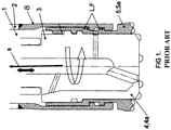
- Putting together of a drilling head according to figure 1 takes place typically so that an essentially elongated, in a manner of speaking sleeve-like, casing shoe is being cut during a mounting phase in a machine shop longitudinally at one point and spread open, whereafter it is being pressed together over the reamer. After this, it is being welded by its cutting point back to form once again as a uniform ring.
- the most remarkable disadvantage of this kind of a structure, being welded together is the weak point due to the welding seam in the casing shoe, which gets very easily broken under difficult circumstances.
- a further disadvantage of this solution are thus those "extra" working phases related thereto, because the casing shoe must first of all be cut longitudinally, pressed onto the reamer and finally once again welded together.
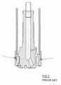
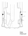
- the drilling device according to figure 2 is being put together by the shrinking method explained above that is by pressing and the one shown in figure 3 by using a screw joint, in which case the screw joint does not, however, carry load during drilling.
- plastic pipe drilling typically e.g. well drilling or e.g. forepoling
- An advantage of use of a plastic pipe in drilling is first of all the fact that plastic pipes are very light compared to steel pipes, thanks to which they also have more profitable transport costs and they are easier to handle at a construction site. Furthermore a plastic pipe is significantly cheaper than a corresponding steel pipe.
- a plastic pipe does not rust for that matter and when being mounted into the ground, it does not break the bits of crushers or drills, when the soil is later on being e.g. worked or drilled.
- metal may not blend with broken rocks, which is why use of plastic pipes in drilling has a very remarkable meaning in that context as well.
- the drilling unit can be coupled in a machine shop in a preliminary working phase to be coupled, as an advantageous embodiment as a separate part, with the end of the casing part, which for its part can be coupled with traditional arrangements as such furthermore in connection with the end of the casing part endways or e.g. partly in an overlapping manner e.g. by flash welding, spot welding, glueing, or by mechanical arrangements, such as by a screw, cotter pin, snap lock joint or correspondingly etc.
- a further crucial advantage of the invention is furthermore the fact that it enables increasing the efficiency of production with a view to both traditional metal pipe drilling and plastic pipe drilling.
- a coupling between the reamer and the casing part, being produced according to the invention can be carried out by exploiting shrinking technique more efficiently than before and when needed even with bigger dimensions than the solutions described in the beginning, particularly thanks to the simple structure of the reamer's skirt part, in which case the wall thicknesses thereof can be minimized when compared to traditional casing shoe constructions.
- the invention relates first of all to a method in putting together of a down-the-hole drilling apparatus, which apparatus has a drilling device 1 that consists of a casing part 2 and a drilling unit 3 connected to the casing part (2) at least during a drilling situation, which drilling unit includes a drilling head and a drilling arrangement therein, said drilling arrangement comprising first drilling means 4 for drilling a center hole and second drilling means 5 for reaming the center hole for the casing part 2, the drilling means 4, 5 being coupled on the first hand at least during a drilling situation mutually in a power transmitting manner in order to carry out co-operation thereof for a rotational motion, a feeding motion and/or a hammering motion, and on the other hand removably in connection with the casing part 2 in order to enable at least removal of the first drilling means 4 from a drilled hole.
- the casing part 2 is arranged to be pulled into the hole to be drilled by a power influence directed thereto from the drilling unit 3 through a shoulder arrangement being arranged at an end of the casing part.
- a shoulder arrangement being arranged at an end of the casing part.
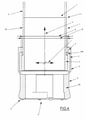
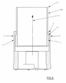
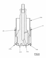
- At an opposite end II of the drilling arrangement with respect to a drilling surface P of the drilling unit 3, there is arranged e.g. as shown in figure 4 a built-in skirt part z, which has in radial direction r an internal shoulder arrangement x for pulling the casing part 2 into the hole to be drilled by co-operation of the said internal shoulder arrangement x and the external shoulder arrangement y arranged at the end I of the casing part.
- the internal shoulder arrangement x in connection with the second drilling means 5, comprising an internal flange at an end of the shrinkable skirt part z, is being manufactured on the principle that manifests itself in figure 4 by its inner diameter D essentially larger than the outer diameter d of the corresponding external shoulder arrangement y of the casing part 2, such as a cantilever flange at an end thereof, whereby a mutual joint L2 between the parts in question that transmits pulling in longitudinal direction s is being formed on the principle that manifests itself in figure 5 by placing the shoulder arrangements x, y, being put on top of each other, to overlap one another and by shrinking F1 by radially pressing the shrinkable skirt part z and the internal shoulder arrangement x that is placed in the longitudinal direction s behind the external shoulder arrangement y, in order to diminish its inner diameter smaller than the outer diameter of the external shoulder arrangement y.
- the drilling head of the drilling unit 3 is formed of a first frame part 4a and a second frame part 5a, wherein drilling surfaces P; P1, P2 formed of end surfaces of the above frame parts are provided with drilling organs of the first and the second drilling means 4, 5, such as an integrated drilling part, separate drilling pieces, bits or like.
- drilling surfaces P; P1, P2 formed of end surfaces of the above frame parts are provided with drilling organs of the first and the second drilling means 4, 5, such as an integrated drilling part, separate drilling pieces, bits or like.
- the extension part 2a is being coupled with the end of the casing part 2 by what ever suitable joint arrangement L1 e.g. with mechanical means, chemical means and/or means based on melting.
- an essentially unpreworked raw pipe preform is being used, which is manufactured particularly for food stuff utilization preferably from PEH-, PVC-plastic or the like and/or from reinforced plastic, such as fibre-reinforced plastic or the like.
- y is being placed (e.g. by pushing in its place from behind prior to radial pressing together of the skirt part z) at least one wear/slide ring a particularly in order to minimize thermal influence directed to the external shoulder arrangement y.
- a wear/slide ring a made of e.g. plastic, metal, composite and/or ceramic material acts as a slide surface for the internal shoulder arrangement x, in which case heat or wear is not directed to the external shoulder arrangement y.
- y in the longitudinal direction s between the shoulder arrangements x, y is being placed at least one elastic/friction ring b particularly in order to minimize impact and thermal influence directed to the external shoulder arrangement y.
- the elastic/friction ring above e.g. made of elastic plastic, rubber, silicon and/or the like material and that is placed advantageously directly against the external shoulder arrangement y absorbs e.g. vibration directed to the external shoulder arrangement from a hammering motion and eliminates rotative motion taking place against it, in which case excessive heating thereof can be avoided.
- the invention relates on the other hand to a down-the-hole drilling apparatus, which has a drilling device 1 that consists of a casing part 2 and a drilling unit 3 connected to the casing part (2) at least during a drilling situation, which drilling unit includes a drilling head and a drilling arrangement therein, said drilling arrangement comprising first drilling means 4 for drilling a center hole and second drilling means 5 for reaming the center hole for the casing part 2, the drilling means 4, 5 being coupled on the first hand at least during a drilling situation mutually in a power transmitting manner in order to carry out co-operation thereof for a rotational motion, a feeding motion and/or a hammering motion, and on the other hand removably in connection with the casing part 2 in order to enable at least removal of the first drilling means 4 from a drilled hole.
- the casing part 2 is arranged to be pulled into the hole to be drilled by a power influence directed thereto from the drilling unit 3 through a shoulder arrangement being arranged at an end of the casing part.
- a shoulder arrangement being arranged at an end of the casing part.
- a mutual joint L2 between the second drilling means 5 and the casing 2 is formed that transmits pulling in longitudinal direction s on the principle shown in figure 5 by placing the shoulder arrangements x, y, being put on top of each other, to overlap one another and by shrinking F1 the internal shoulder arrangement x that is placed in the longitudinal direction s behind the external shoulder arrangement y.
- the second drilling means 5 and the casing part 2 have a mutual shrink joint L2, in which the internal shoulder arrangement x in a the shrinkable skirt part z of the second drilling means 5 is placed in the longitudinal direction s behind the external shoulder arrangement y.
- the mutual shrink joint L2 is formed by radially pressing the shrinkable skirt part z and the internal shoulder arrangement x, so that the inner diameter of the internal shoulder arrangement x is smaller than the outer diameter of the external shoulder arrangement.
- the drilling head of the drilling unit 3 is formed of a first frame part 4a and a second frame part 5a, wherein drilling surfaces P; P1, P2 formed of end surfaces of the above frame parts are provided with drilling organs of the first and the second drilling means 4, 5, such as an integrated drilling part, separate drilling pieces, bits or like, and, whereby at the end of the casing part 2 is arranged an extension part to be fastened thereto separately and that is equipped with a shoulder arrangement.
- the extension part 2a provided with an external shoulder arrangement y is coupled with the end of the casing part 2 e.g. by a joint arrangement L1 with mechanical means, chemical means and/or means based on melting.
- the casing part 2 is an essentially unpreworked raw pipe preform, which is manufactured particularly for food stuff utilization preferably from PEH-, PVC-plastic or the like and/or from reinforced plastic, such as fibre-reinforced plastic or the like. Furthermore, in the longitudinal direction s between the shoulder arrangements x, y, is arranged with reference to the advantageous embodiment shown in figures 4 , 6 and 7 at least one:
Landscapes
- Engineering & Computer Science (AREA)
- Life Sciences & Earth Sciences (AREA)
- Geology (AREA)
- Mining & Mineral Resources (AREA)
- Physics & Mathematics (AREA)
- Environmental & Geological Engineering (AREA)
- Fluid Mechanics (AREA)
- General Life Sciences & Earth Sciences (AREA)
- Geochemistry & Mineralogy (AREA)
- Mechanical Engineering (AREA)
- Earth Drilling (AREA)
Claims (10)
- Verfahren zum Kombinieren einer Abwärtsbohrvorrichtung, wobei die Vorrichtung eine Bohrvorrichtung (1) aufweist, die aus einem Mantelteil (2) und einer Bohreinheit (3) besteht, die zumindest während einer Bohrsituation mit dem Mantelteil (2) verbunden ist, wobei die Bohreinheit einen Bohrkopf mit darin einer Bohranordnung enthält, wobei die Bohranordnung ein erstes Bohrmittel (4) zum Bohren eines Mittellochs und ein zweites Bohrmittel (5) zum Aufweiten des Mittellochs für den Mantelteil (2) umfasst, wobei die Bohrmittel (4, 5) einerseits während einer Bohrsituation in einer kraftübertragenden Weise miteinander gekoppelt sind, um durch ihr Zusammenwirken eine Drehbewegung, eine Vorschubbewegung und/oder eine Schlagbewegung auszuführen, und andererseits entfernbar mit dem Mantelteil (2) verbunden sind, um zumindest das Entfernen des ersten Bohrmittels (4) aus einem gebohrten Loch zu ermöglichen, wobei das Mantelteil (2) so angeordnet ist, dass es durch einen über eine an einem Ende des Mantelteils angeordneten Schulteranordnung darauf gerichteten Krafteinfluss von der Bohreinheit (3) in das zu bohrende Loch gezogen wird, und wobei an einem gegenüberliegenden Ende (II) der Bohranordnung in Bezug auf eine Bohrfläche (P) der Bohreinheit (3) ein eingebautes Einfassungsteil (z) angeordnet ist, das in radialer Richtung (r) eine innere Schulteranordnung (x) zum Einziehen des Mantelteils (2) in das zu bohrende Loch durch Zusammenwirken der genannten inneren Schulteranordnung (x) und der am Ende (I) des Mantelteils angeordneten äußeren Schulteranordnung (y) aufweist, dadurch gekennzeichnet, dass die innere Schulteranordnung (x), die einen Innenflansch an einem Ende des schrumpfbaren Einfassungsteils (z) des zweiten Bohrmittels (5) umfasst, durch ihren Innendurchmesser (D) wesentlich größer als der Außendurchmesser (d) der entsprechenden äußeren Schulteranordnung (y) des Mantelteils (2) hergestellt wird, wobei durch ein überlappendes Übereinanderlegen der Schulteranordnungen (x, y) mit der inneren Schulteranordnung (x) in der Längsrichtung (s) hinter der äußeren Schulteranordnung (y) und durch Schrumpfen (F1) durch radiales Pressen des schrumpfbaren Einfassungsteils (z) und der inneren Schulteranordnung (x) in dem schrumpfbaren Einfassungsteil (z), um dessen Innendurchmesser kleiner als den Außendurchmesser der äußeren Schulteranordnung zu verkleinern, eine gegenseitige Verbindung (L2) zwischen den fraglichen Teilen, die Zug in Längsrichtung (s) überträgt, gebildet wird.
- Verfahren nach Anspruch 1 bei Verwendung einer Vorrichtung, bei welcher der Bohrkopf der Bohreinheit (3) aus einem ersten Rahmenteil (4a) und einem zweiten Rahmenteil (5a) gebildet ist, wobei Bohrflächen (P; P1, P2), die von Endflächen der obigen Rahmenteile gebildet werden, mit Bohrelementen des ersten und des zweiten Bohrmittels (4, 5), wie einem integrierten Bohrteil, separaten Bohrstücken, Meißeln oder dergleichen, versehen sind, und wobei am Ende des Mantelteils (2) ein daran separat zu befestigendes Verlängerungsteil angeordnet ist, das mit einer Schulteranordnung ausgestattet ist, dadurch gekennzeichnet, dass das mit einer äußeren Schulteranordnung (y) versehene Verlängerungsteil (2a) durch eine Verbindungsanordnung (L1) mit mechanischen Mitteln, chemischen Mitteln und/oder auf Schmelzen basierenden Mitteln mit dem Ende des Mantelteils (2) verbunden ist.
- Verfahren nach Anspruch 1 oder 2, dadurch gekennzeichnet, dass als Mantelteil (2) für das Kunststoffrohrbohren ein nicht vorbearbeiteter Rohrvorformling verwendet wird, der aus PEH-, PVC-Kunststoff oder dergleichen und/oder aus verstärktem Kunststoff, wie faserverstärktem Kunststoff oder dergleichen, hergestellt ist.
- Verfahren nach Anspruch 3, dadurch gekennzeichnet, dass in der Längsrichtung (s) zwischen den Schulteranordnungen (x, y) mindestens ein Verschleiß-/Gleitring (a) eingebaut ist, insbesondere um die thermische Beeinflussung der äußeren Schulteranordnung (y) zu minimieren.
- Verfahren nach Anspruch 3 oder 4, dadurch gekennzeichnet, dass in der Längsrichtung (s) zwischen den Schulteranordnungen (x, y) mindestens ein Gummi-/Reibring (b) eingebaut ist, insbesondere um die thermische Beeinflussung der äußeren Schulteranordnung (y) zu minimieren.
- Abwärtsbohrvorrichtung, die eine Bohrvorrichtung (1) aufweist, die aus einem Mantelteil (2) und einer Bohreinheit (3) besteht, die zumindest während einer Bohrsituation mit dem Mantelteil (2) verbunden ist, wobei die Bohreinheit einen Bohrkopf mit darin einer Bohranordnung enthält, wobei die Bohranordnung ein erstes Bohrmittel (4) zum Bohren eines Mittellochs und ein zweites Bohrmittel (5) zum Aufweiten des Mittellochs für den Mantelteil (2) umfasst, wobei die Bohrmittel (4, 5) einerseits während einer Bohrsituation in einer kraftübertragenden Weise miteinander gekoppelt sind, um durch ihr Zusammenwirken eine Drehbewegung, eine Vorschubbewegung und/oder eine Schlagbewegung auszuführen, und andererseits entfernbar mit dem Mantelteil (2) verbunden sind, um zumindest das Entfernen des ersten Bohrmittels (4) aus einem gebohrten Loch zu ermöglichen, wobei das Mantelteil (2) so angeordnet ist, dass es durch einen über eine an einem Ende des Mantelteils angeordneten Schulteranordnung darauf gerichteten Krafteinfluss von der Bohreinheit (3) in das zu bohrende Loch gezogen wird, und wobei an einem gegenüberliegenden Ende (II) der Bohranordnung in Bezug auf eine Bohrfläche (P) der Bohreinheit (3) ein eingebautes Einfassungsteil (z) angeordnet ist, das in radialer Richtung (r) eine innere Schulteranordnung (x) zum Einziehen des Mantelteils (2) in das zu bohrende Loch durch Zusammenwirken der genannten inneren Schulteranordnung (x) und der am Ende (I) des Mantelteils angeordneten äußeren Schulteranordnung (y) aufweist, dadurch gekennzeichnet, dass das zweite Bohrmittel (5) und das Mantelteil (2) eine gegenseitige Schrumpfverbindung (L2)aufweisen, bei der die innere Schulteranordnung (x) in einem schrumpfbaren Einfassungsteil (z) des zweiten Bohrmittels (5) in der Längsrichtung (s) hinter der äußeren Schulteranordnung (y) angeordnet ist, wobei die gegenseitige Schrumpfverbindung (L2) durch radiales Pressen des schrumpfbaren Einfassungsteils (z) und der inneren Schulteranordnung (x) gebildet wird, sodass der Innendurchmesser der inneren Schulteranordnung (x) kleiner ist als der Außendurchmesser der äußeren Schulteranordnung (y).
- Vorrichtung nach Anspruch 6, bei welcher der Bohrkopf der Bohreinheit (3) aus einem ersten Rahmenteil (4a) und einem zweiten Rahmenteil (5a) gebildet ist, wobei Bohrflächen (P; P1, P2), die von Endflächen der obigen Rahmenteile gebildet werden, mit Bohrelementen des ersten und des zweiten Bohrmittels (4, 5), wie einem integrierten Bohrteil, separaten Bohrstücken, Meißeln oder dergleichen, versehen sind, und wobei am Ende des Mantelteils (2) ein mit einer Verbindung separat daran zu befestigendes Verlängerungsteil angeordnet ist, das mit einer Schulteranordnung ausgestattet ist, dadurch gekennzeichnet, dass die Verbindung zwischen dem mit einer äußeren Schulteranordnung (y) versehenen Verlängerungsteil (2a) und dem Ende des Mantelteils (2) eine Verbindungsanordnung (L1) mit mechanischen Mitteln, chemischen Mitteln und/oder auf Schmelzen basierenden Mitteln umfasst.
- Vorrichtung nach Anspruch 6 oder 7, dadurch gekennzeichnet, dass das Mantelteil (2) für das Kunststoffrohrbohren aus einem nicht vorbearbeiteten Rohrvorformling besteht, der aus PEH-, PVC-Kunststoff oder dergleichen und/oder aus verstärktem Kunststoff, wie faserverstärktem Kunststoff oder dergleichen, hergestellt ist.
- Vorrichtung nach Anspruch 8, dadurch gekennzeichnet, dass in der Längsrichtung (s) zwischen den Schulteranordnungen (x, y) mindestens ein Verschleiß-/Gleitring (a) angeordnet ist, insbesondere um die thermische Beeinflussung der äußeren Schulteranordnung (y) zu minimieren.
- Vorrichtung nach Anspruch 8 oder 9, dadurch gekennzeichnet, dass in der Längsrichtung (s) zwischen den Schulteranordnungen (x, y) mindestens ein Gummi-/Reibring (b) angeordnet ist, insbesondere um die thermische Beeinflussung der äußeren Schulteranordnung (y) zu minimieren.
Applications Claiming Priority (2)
| Application Number | Priority Date | Filing Date | Title |
|---|---|---|---|
| FI20135794 | 2013-07-26 | ||
| PCT/FI2014/050366 WO2015011336A1 (en) | 2013-07-26 | 2014-05-15 | Method in putting together of a down-the-hole drilling apparatus and a down-the-hole drilling apparatus |
Publications (3)
| Publication Number | Publication Date |
|---|---|
| EP3011127A1 EP3011127A1 (de) | 2016-04-27 |
| EP3011127A4 EP3011127A4 (de) | 2017-03-08 |
| EP3011127B1 true EP3011127B1 (de) | 2022-01-19 |
Family
ID=51868627
Family Applications (1)
| Application Number | Title | Priority Date | Filing Date |
|---|---|---|---|
| EP14829014.1A Active EP3011127B1 (de) | 2013-07-26 | 2014-05-15 | Verfahren zum zusammensetzen einer abwärtsbohrvorrichtung sowie abwärtsbohrvorrichtung |
Country Status (4)
| Country | Link |
|---|---|
| US (1) | US9970238B2 (de) |
| EP (1) | EP3011127B1 (de) |
| FI (1) | FI10639U1 (de) |
| WO (1) | WO2015011336A1 (de) |
Families Citing this family (2)
| Publication number | Priority date | Publication date | Assignee | Title |
|---|---|---|---|---|
| MX2019009794A (es) * | 2018-08-17 | 2020-02-18 | Ancor Loc Nz Ltd | Herramienta para desatascar un pozo o diametro interno. |
| CN119914177A (zh) | 2023-10-30 | 2025-05-02 | 肯纳金属印度有限公司 | 钻土工具 |
Family Cites Families (15)
| Publication number | Priority date | Publication date | Assignee | Title |
|---|---|---|---|---|
| FR2209038B1 (de) * | 1972-12-06 | 1977-07-22 | Petroles Cie Francaise | |
| US5150636A (en) * | 1991-06-28 | 1992-09-29 | Loudon Enterprises, Inc. | Rock drill bit and method of making same |
| FI95618C (fi) | 1992-12-03 | 1998-09-03 | Jorma Jaervelae | Porauslaitteisto |
| SE9401349D0 (sv) | 1994-04-21 | 1994-04-21 | Atlas Copco Rocktech Ab | Foderrör med slagsko |
| US5839519A (en) * | 1996-11-08 | 1998-11-24 | Sandvik Ab | Methods and apparatus for attaching a casing to a drill bit in overburden drilling equipment |
| WO2000031373A1 (en) * | 1998-11-23 | 2000-06-02 | Ilomaeki Valto | A method for mounting a casing shoe on a drilling apparatus |
| US6755447B2 (en) | 2001-08-24 | 2004-06-29 | The Technologies Alliance, Inc. | Production riser connector |
| US7182156B2 (en) * | 2003-06-12 | 2007-02-27 | Luc Charland | System for overburden drilling |
| FI121635B (fi) * | 2006-04-27 | 2011-02-15 | Pirkan Laatupalvelu Oy | Porauspään huuhtelujärjestely |
| FI20070540A0 (fi) | 2007-07-10 | 2007-07-10 | Robit Rocktools Ltd | Teräsovitelma |
| CN201083085Y (zh) | 2007-07-19 | 2008-07-09 | 李斌 | 无焊接潜孔钻钻杆 |
| FI20085237A7 (fi) * | 2008-03-19 | 2009-09-20 | Oy Atlas Copco Rotex Ab | Liitosjärjestely maakengän kytkemiseksi |
| FI125204B (fi) | 2010-10-15 | 2015-06-30 | Robit Rocktools Ltd | Porasovitelma |
| JP5849671B2 (ja) * | 2011-12-09 | 2016-02-03 | 三菱マテリアル株式会社 | 掘削工具 |
| JP3177561U (ja) * | 2012-05-28 | 2012-08-09 | 貞司 内海 | 耐震構造合板 |
-
2014
- 2014-05-15 US US14/895,097 patent/US9970238B2/en active Active
- 2014-05-15 WO PCT/FI2014/050366 patent/WO2015011336A1/en not_active Ceased
- 2014-05-15 FI FIU20144109U patent/FI10639U1/fi active IP Right Grant
- 2014-05-15 EP EP14829014.1A patent/EP3011127B1/de active Active
Also Published As
| Publication number | Publication date |
|---|---|
| WO2015011336A1 (en) | 2015-01-29 |
| US9970238B2 (en) | 2018-05-15 |
| EP3011127A4 (de) | 2017-03-08 |
| EP3011127A1 (de) | 2016-04-27 |
| US20160130879A1 (en) | 2016-05-12 |
| FI10639U1 (fi) | 2014-10-09 |
Similar Documents
| Publication | Publication Date | Title |
|---|---|---|
| US8051927B2 (en) | Percussive drill bit for rock drilling and method for the manufacture of such a drill bit | |
| KR101661031B1 (ko) | 임팩트 기기 및 이를 분리하는 방법 | |
| JP3968309B2 (ja) | 掘削方法およびドリル装置 | |
| EP3011127B1 (de) | Verfahren zum zusammensetzen einer abwärtsbohrvorrichtung sowie abwärtsbohrvorrichtung | |
| US20110198129A1 (en) | Method and drilling apparatus for down-the-hole drilling | |
| US9611701B2 (en) | Method and apparatus for plastic pipe drilling | |
| EP3175077B1 (de) | Verfahren zum zusammensetzen einer abwärtsbohrvorrichtung zum kunststoffrohrbohren und einer zweiten abwärtsbohrvorrichtung | |
| US20160201409A1 (en) | Method for putting together of a drilling device and drilling device | |
| WO2009115638A1 (en) | Joint arrangement for coupling of a drill shoe | |
| WO2014001601A1 (en) | Method and apparatus for use of a drilling device meant for down-the-hole drilling | |
| CN102852157A (zh) | 顶部固定水钻法人工挖孔桩方法 | |
| KR101258506B1 (ko) | 지반 천공장치의 해머비트 구조 | |
| SE530357C2 (sv) | Anordning vid utförande av borrning i jordlager och berg | |
| WO2026093659A1 (en) | Method for assembling a down-the-hole drilling apparatus for plastic pipe drilling and a down-the-hole drilling apparatus | |
| CN103742080A (zh) | 主动复合钻杆 | |
| WO2010095998A1 (en) | A start kit, a casing tube and a starter rod for drilling equipments for percussive rock drilling |
Legal Events
| Date | Code | Title | Description |
|---|---|---|---|
| PUAI | Public reference made under article 153(3) epc to a published international application that has entered the european phase |
Free format text: ORIGINAL CODE: 0009012 |
|
| 17P | Request for examination filed |
Effective date: 20160119 |
|
| AK | Designated contracting states |
Kind code of ref document: A1 Designated state(s): AL AT BE BG CH CY CZ DE DK EE ES FI FR GB GR HR HU IE IS IT LI LT LU LV MC MK MT NL NO PL PT RO RS SE SI SK SM TR |
|
| AX | Request for extension of the european patent |
Extension state: BA ME |
|
| DAX | Request for extension of the european patent (deleted) | ||
| A4 | Supplementary search report drawn up and despatched |
Effective date: 20170207 |
|
| RIC1 | Information provided on ipc code assigned before grant |
Ipc: E21B 7/20 20060101ALI20170201BHEP Ipc: E21B 17/04 20060101ALI20170201BHEP Ipc: E21B 17/14 20060101AFI20170201BHEP |
|
| RAP1 | Party data changed (applicant data changed or rights of an application transferred) |
Owner name: OY EPIROC DRILLING TOOLS AB |
|
| RAP1 | Party data changed (applicant data changed or rights of an application transferred) |
Owner name: TERRAROC FINLAND OY |
|
| GRAP | Despatch of communication of intention to grant a patent |
Free format text: ORIGINAL CODE: EPIDOSNIGR1 |
|
| STAA | Information on the status of an ep patent application or granted ep patent |
Free format text: STATUS: GRANT OF PATENT IS INTENDED |
|
| INTG | Intention to grant announced |
Effective date: 20210716 |
|
| GRAS | Grant fee paid |
Free format text: ORIGINAL CODE: EPIDOSNIGR3 |
|
| GRAJ | Information related to disapproval of communication of intention to grant by the applicant or resumption of examination proceedings by the epo deleted |
Free format text: ORIGINAL CODE: EPIDOSDIGR1 |
|
| GRAL | Information related to payment of fee for publishing/printing deleted |
Free format text: ORIGINAL CODE: EPIDOSDIGR3 |
|
| STAA | Information on the status of an ep patent application or granted ep patent |
Free format text: STATUS: REQUEST FOR EXAMINATION WAS MADE |
|
| GRAP | Despatch of communication of intention to grant a patent |
Free format text: ORIGINAL CODE: EPIDOSNIGR1 |
|
| STAA | Information on the status of an ep patent application or granted ep patent |
Free format text: STATUS: GRANT OF PATENT IS INTENDED |
|
| INTC | Intention to grant announced (deleted) | ||
| GRAA | (expected) grant |
Free format text: ORIGINAL CODE: 0009210 |
|
| STAA | Information on the status of an ep patent application or granted ep patent |
Free format text: STATUS: THE PATENT HAS BEEN GRANTED |
|
| INTG | Intention to grant announced |
Effective date: 20211210 |
|
| AK | Designated contracting states |
Kind code of ref document: B1 Designated state(s): AL AT BE BG CH CY CZ DE DK EE ES FI FR GB GR HR HU IE IS IT LI LT LU LV MC MK MT NL NO PL PT RO RS SE SI SK SM TR |
|
| REG | Reference to a national code |
Ref country code: GB Ref legal event code: FG4D |
|
| REG | Reference to a national code |
Ref country code: CH Ref legal event code: EP |
|
| REG | Reference to a national code |
Ref country code: DE Ref legal event code: R096 Ref document number: 602014082246 Country of ref document: DE |
|
| REG | Reference to a national code |
Ref country code: AT Ref legal event code: REF Ref document number: 1463906 Country of ref document: AT Kind code of ref document: T Effective date: 20220215 |
|
| REG | Reference to a national code |
Ref country code: IE Ref legal event code: FG4D |
|
| REG | Reference to a national code |
Ref country code: FI Ref legal event code: FGE |
|
| REG | Reference to a national code |
Ref country code: SE Ref legal event code: TRGR |
|
| REG | Reference to a national code |
Ref country code: LT Ref legal event code: MG9D |
|
| REG | Reference to a national code |
Ref country code: NL Ref legal event code: MP Effective date: 20220119 |
|
| REG | Reference to a national code |
Ref country code: NO Ref legal event code: T2 Effective date: 20220119 |
|
| REG | Reference to a national code |
Ref country code: AT Ref legal event code: MK05 Ref document number: 1463906 Country of ref document: AT Kind code of ref document: T Effective date: 20220119 |
|
| PG25 | Lapsed in a contracting state [announced via postgrant information from national office to epo] |
Ref country code: NL Free format text: LAPSE BECAUSE OF FAILURE TO SUBMIT A TRANSLATION OF THE DESCRIPTION OR TO PAY THE FEE WITHIN THE PRESCRIBED TIME-LIMIT Effective date: 20220119 |
|
| PG25 | Lapsed in a contracting state [announced via postgrant information from national office to epo] |
Ref country code: RS Free format text: LAPSE BECAUSE OF FAILURE TO SUBMIT A TRANSLATION OF THE DESCRIPTION OR TO PAY THE FEE WITHIN THE PRESCRIBED TIME-LIMIT Effective date: 20220119 Ref country code: PT Free format text: LAPSE BECAUSE OF FAILURE TO SUBMIT A TRANSLATION OF THE DESCRIPTION OR TO PAY THE FEE WITHIN THE PRESCRIBED TIME-LIMIT Effective date: 20220519 Ref country code: LT Free format text: LAPSE BECAUSE OF FAILURE TO SUBMIT A TRANSLATION OF THE DESCRIPTION OR TO PAY THE FEE WITHIN THE PRESCRIBED TIME-LIMIT Effective date: 20220119 Ref country code: HR Free format text: LAPSE BECAUSE OF FAILURE TO SUBMIT A TRANSLATION OF THE DESCRIPTION OR TO PAY THE FEE WITHIN THE PRESCRIBED TIME-LIMIT Effective date: 20220119 Ref country code: ES Free format text: LAPSE BECAUSE OF FAILURE TO SUBMIT A TRANSLATION OF THE DESCRIPTION OR TO PAY THE FEE WITHIN THE PRESCRIBED TIME-LIMIT Effective date: 20220119 Ref country code: BG Free format text: LAPSE BECAUSE OF FAILURE TO SUBMIT A TRANSLATION OF THE DESCRIPTION OR TO PAY THE FEE WITHIN THE PRESCRIBED TIME-LIMIT Effective date: 20220419 |
|
| PG25 | Lapsed in a contracting state [announced via postgrant information from national office to epo] |
Ref country code: PL Free format text: LAPSE BECAUSE OF FAILURE TO SUBMIT A TRANSLATION OF THE DESCRIPTION OR TO PAY THE FEE WITHIN THE PRESCRIBED TIME-LIMIT Effective date: 20220119 Ref country code: LV Free format text: LAPSE BECAUSE OF FAILURE TO SUBMIT A TRANSLATION OF THE DESCRIPTION OR TO PAY THE FEE WITHIN THE PRESCRIBED TIME-LIMIT Effective date: 20220119 Ref country code: GR Free format text: LAPSE BECAUSE OF FAILURE TO SUBMIT A TRANSLATION OF THE DESCRIPTION OR TO PAY THE FEE WITHIN THE PRESCRIBED TIME-LIMIT Effective date: 20220420 Ref country code: AT Free format text: LAPSE BECAUSE OF FAILURE TO SUBMIT A TRANSLATION OF THE DESCRIPTION OR TO PAY THE FEE WITHIN THE PRESCRIBED TIME-LIMIT Effective date: 20220119 |
|
| PG25 | Lapsed in a contracting state [announced via postgrant information from national office to epo] |
Ref country code: IS Free format text: LAPSE BECAUSE OF FAILURE TO SUBMIT A TRANSLATION OF THE DESCRIPTION OR TO PAY THE FEE WITHIN THE PRESCRIBED TIME-LIMIT Effective date: 20220519 |
|
| REG | Reference to a national code |
Ref country code: DE Ref legal event code: R097 Ref document number: 602014082246 Country of ref document: DE |
|
| PG25 | Lapsed in a contracting state [announced via postgrant information from national office to epo] |
Ref country code: SM Free format text: LAPSE BECAUSE OF FAILURE TO SUBMIT A TRANSLATION OF THE DESCRIPTION OR TO PAY THE FEE WITHIN THE PRESCRIBED TIME-LIMIT Effective date: 20220119 Ref country code: SK Free format text: LAPSE BECAUSE OF FAILURE TO SUBMIT A TRANSLATION OF THE DESCRIPTION OR TO PAY THE FEE WITHIN THE PRESCRIBED TIME-LIMIT Effective date: 20220119 Ref country code: RO Free format text: LAPSE BECAUSE OF FAILURE TO SUBMIT A TRANSLATION OF THE DESCRIPTION OR TO PAY THE FEE WITHIN THE PRESCRIBED TIME-LIMIT Effective date: 20220119 Ref country code: EE Free format text: LAPSE BECAUSE OF FAILURE TO SUBMIT A TRANSLATION OF THE DESCRIPTION OR TO PAY THE FEE WITHIN THE PRESCRIBED TIME-LIMIT Effective date: 20220119 Ref country code: DK Free format text: LAPSE BECAUSE OF FAILURE TO SUBMIT A TRANSLATION OF THE DESCRIPTION OR TO PAY THE FEE WITHIN THE PRESCRIBED TIME-LIMIT Effective date: 20220119 Ref country code: CZ Free format text: LAPSE BECAUSE OF FAILURE TO SUBMIT A TRANSLATION OF THE DESCRIPTION OR TO PAY THE FEE WITHIN THE PRESCRIBED TIME-LIMIT Effective date: 20220119 |
|
| PLBE | No opposition filed within time limit |
Free format text: ORIGINAL CODE: 0009261 |
|
| STAA | Information on the status of an ep patent application or granted ep patent |
Free format text: STATUS: NO OPPOSITION FILED WITHIN TIME LIMIT |
|
| PG25 | Lapsed in a contracting state [announced via postgrant information from national office to epo] |
Ref country code: AL Free format text: LAPSE BECAUSE OF FAILURE TO SUBMIT A TRANSLATION OF THE DESCRIPTION OR TO PAY THE FEE WITHIN THE PRESCRIBED TIME-LIMIT Effective date: 20220119 |
|
| REG | Reference to a national code |
Ref country code: DE Ref legal event code: R119 Ref document number: 602014082246 Country of ref document: DE |
|
| 26N | No opposition filed |
Effective date: 20221020 |
|
| REG | Reference to a national code |
Ref country code: CH Ref legal event code: PL |
|
| REG | Reference to a national code |
Ref country code: BE Ref legal event code: MM Effective date: 20220531 |
|
| GBPC | Gb: european patent ceased through non-payment of renewal fee |
Effective date: 20220515 |
|
| PG25 | Lapsed in a contracting state [announced via postgrant information from national office to epo] |
Ref country code: MC Free format text: LAPSE BECAUSE OF FAILURE TO SUBMIT A TRANSLATION OF THE DESCRIPTION OR TO PAY THE FEE WITHIN THE PRESCRIBED TIME-LIMIT Effective date: 20220119 Ref country code: LU Free format text: LAPSE BECAUSE OF NON-PAYMENT OF DUE FEES Effective date: 20220515 Ref country code: LI Free format text: LAPSE BECAUSE OF NON-PAYMENT OF DUE FEES Effective date: 20220531 Ref country code: CH Free format text: LAPSE BECAUSE OF NON-PAYMENT OF DUE FEES Effective date: 20220531 |
|
| PG25 | Lapsed in a contracting state [announced via postgrant information from national office to epo] |
Ref country code: SI Free format text: LAPSE BECAUSE OF FAILURE TO SUBMIT A TRANSLATION OF THE DESCRIPTION OR TO PAY THE FEE WITHIN THE PRESCRIBED TIME-LIMIT Effective date: 20220119 |
|
| PG25 | Lapsed in a contracting state [announced via postgrant information from national office to epo] |
Ref country code: FR Free format text: LAPSE BECAUSE OF NON-PAYMENT OF DUE FEES Effective date: 20220531 |
|
| PG25 | Lapsed in a contracting state [announced via postgrant information from national office to epo] |
Ref country code: GB Free format text: LAPSE BECAUSE OF NON-PAYMENT OF DUE FEES Effective date: 20220515 Ref country code: DE Free format text: LAPSE BECAUSE OF NON-PAYMENT OF DUE FEES Effective date: 20221201 Ref country code: BE Free format text: LAPSE BECAUSE OF NON-PAYMENT OF DUE FEES Effective date: 20220531 |
|
| P01 | Opt-out of the competence of the unified patent court (upc) registered |
Effective date: 20230528 |
|
| PG25 | Lapsed in a contracting state [announced via postgrant information from national office to epo] |
Ref country code: IT Free format text: LAPSE BECAUSE OF FAILURE TO SUBMIT A TRANSLATION OF THE DESCRIPTION OR TO PAY THE FEE WITHIN THE PRESCRIBED TIME-LIMIT Effective date: 20220119 |
|
| REG | Reference to a national code |
Ref country code: FI Ref legal event code: PCE Owner name: TERRAROC FINLAND OY |
|
| PG25 | Lapsed in a contracting state [announced via postgrant information from national office to epo] |
Ref country code: HU Free format text: LAPSE BECAUSE OF FAILURE TO SUBMIT A TRANSLATION OF THE DESCRIPTION OR TO PAY THE FEE WITHIN THE PRESCRIBED TIME-LIMIT; INVALID AB INITIO Effective date: 20140515 |
|
| PG25 | Lapsed in a contracting state [announced via postgrant information from national office to epo] |
Ref country code: MK Free format text: LAPSE BECAUSE OF FAILURE TO SUBMIT A TRANSLATION OF THE DESCRIPTION OR TO PAY THE FEE WITHIN THE PRESCRIBED TIME-LIMIT Effective date: 20220119 Ref country code: CY Free format text: LAPSE BECAUSE OF FAILURE TO SUBMIT A TRANSLATION OF THE DESCRIPTION OR TO PAY THE FEE WITHIN THE PRESCRIBED TIME-LIMIT Effective date: 20220119 |
|
| PG25 | Lapsed in a contracting state [announced via postgrant information from national office to epo] |
Ref country code: MT Free format text: LAPSE BECAUSE OF FAILURE TO SUBMIT A TRANSLATION OF THE DESCRIPTION OR TO PAY THE FEE WITHIN THE PRESCRIBED TIME-LIMIT Effective date: 20220119 |
|
| PGFP | Annual fee paid to national office [announced via postgrant information from national office to epo] |
Ref country code: FI Payment date: 20250428 Year of fee payment: 12 |
|
| PGFP | Annual fee paid to national office [announced via postgrant information from national office to epo] |
Ref country code: NO Payment date: 20250429 Year of fee payment: 12 |
|
| PGFP | Annual fee paid to national office [announced via postgrant information from national office to epo] |
Ref country code: IE Payment date: 20250428 Year of fee payment: 12 |
|
| PGFP | Annual fee paid to national office [announced via postgrant information from national office to epo] |
Ref country code: SE Payment date: 20250428 Year of fee payment: 12 |
|
| PG25 | Lapsed in a contracting state [announced via postgrant information from national office to epo] |
Ref country code: TR Free format text: LAPSE BECAUSE OF FAILURE TO SUBMIT A TRANSLATION OF THE DESCRIPTION OR TO PAY THE FEE WITHIN THE PRESCRIBED TIME-LIMIT Effective date: 20220119 |