EP3011186B1 - Rückstandsentfernende laufradrückschaufel - Google Patents
Rückstandsentfernende laufradrückschaufel Download PDFInfo
- Publication number
- EP3011186B1 EP3011186B1 EP14813765.6A EP14813765A EP3011186B1 EP 3011186 B1 EP3011186 B1 EP 3011186B1 EP 14813765 A EP14813765 A EP 14813765A EP 3011186 B1 EP3011186 B1 EP 3011186B1
- Authority
- EP
- European Patent Office
- Prior art keywords
- impeller
- central point
- axis
- pump
- spiral
- Prior art date
- Legal status (The legal status is an assumption and is not a legal conclusion. Google has not performed a legal analysis and makes no representation as to the accuracy of the status listed.)
- Not-in-force
Links
Images





Classifications
-
- F—MECHANICAL ENGINEERING; LIGHTING; HEATING; WEAPONS; BLASTING
- F04—POSITIVE - DISPLACEMENT MACHINES FOR LIQUIDS; PUMPS FOR LIQUIDS OR ELASTIC FLUIDS
- F04D—NON-POSITIVE-DISPLACEMENT PUMPS
- F04D29/00—Details, component parts, or accessories
- F04D29/18—Rotors
- F04D29/22—Rotors specially for centrifugal pumps
- F04D29/24—Vanes
- F04D29/242—Geometry, shape
-
- F—MECHANICAL ENGINEERING; LIGHTING; HEATING; WEAPONS; BLASTING
- F04—POSITIVE - DISPLACEMENT MACHINES FOR LIQUIDS; PUMPS FOR LIQUIDS OR ELASTIC FLUIDS
- F04D—NON-POSITIVE-DISPLACEMENT PUMPS
- F04D1/00—Radial-flow pumps, e.g. centrifugal pumps; Helico-centrifugal pumps
-
- F—MECHANICAL ENGINEERING; LIGHTING; HEATING; WEAPONS; BLASTING
- F04—POSITIVE - DISPLACEMENT MACHINES FOR LIQUIDS; PUMPS FOR LIQUIDS OR ELASTIC FLUIDS
- F04D—NON-POSITIVE-DISPLACEMENT PUMPS
- F04D13/00—Pumping installations or systems
- F04D13/02—Units comprising pumps and their driving means
-
- F—MECHANICAL ENGINEERING; LIGHTING; HEATING; WEAPONS; BLASTING
- F04—POSITIVE - DISPLACEMENT MACHINES FOR LIQUIDS; PUMPS FOR LIQUIDS OR ELASTIC FLUIDS
- F04D—NON-POSITIVE-DISPLACEMENT PUMPS
- F04D29/00—Details, component parts, or accessories
- F04D29/007—Details, component parts, or accessories especially adapted for liquid pumps
-
- F—MECHANICAL ENGINEERING; LIGHTING; HEATING; WEAPONS; BLASTING
- F04—POSITIVE - DISPLACEMENT MACHINES FOR LIQUIDS; PUMPS FOR LIQUIDS OR ELASTIC FLUIDS
- F04D—NON-POSITIVE-DISPLACEMENT PUMPS
- F04D29/00—Details, component parts, or accessories
- F04D29/18—Rotors
- F04D29/22—Rotors specially for centrifugal pumps
- F04D29/2261—Rotors specially for centrifugal pumps with special measures
- F04D29/2288—Rotors specially for centrifugal pumps with special measures for comminuting, mixing or separating
-
- F—MECHANICAL ENGINEERING; LIGHTING; HEATING; WEAPONS; BLASTING
- F04—POSITIVE - DISPLACEMENT MACHINES FOR LIQUIDS; PUMPS FOR LIQUIDS OR ELASTIC FLUIDS
- F04D—NON-POSITIVE-DISPLACEMENT PUMPS
- F04D29/00—Details, component parts, or accessories
- F04D29/18—Rotors
- F04D29/22—Rotors specially for centrifugal pumps
- F04D29/24—Vanes
- F04D29/242—Geometry, shape
- F04D29/245—Geometry, shape for special effects
-
- F—MECHANICAL ENGINEERING; LIGHTING; HEATING; WEAPONS; BLASTING
- F04—POSITIVE - DISPLACEMENT MACHINES FOR LIQUIDS; PUMPS FOR LIQUIDS OR ELASTIC FLUIDS
- F04D—NON-POSITIVE-DISPLACEMENT PUMPS
- F04D29/00—Details, component parts, or accessories
- F04D29/40—Casings; Connections of working fluid
- F04D29/42—Casings; Connections of working fluid for radial or helico-centrifugal pumps
- F04D29/4206—Casings; Connections of working fluid for radial or helico-centrifugal pumps especially adapted for elastic fluid pumps
-
- F—MECHANICAL ENGINEERING; LIGHTING; HEATING; WEAPONS; BLASTING
- F04—POSITIVE - DISPLACEMENT MACHINES FOR LIQUIDS; PUMPS FOR LIQUIDS OR ELASTIC FLUIDS
- F04D—NON-POSITIVE-DISPLACEMENT PUMPS
- F04D7/00—Pumps adapted for handling specific fluids, e.g. by selection of specific materials for pumps or pump parts
- F04D7/02—Pumps adapted for handling specific fluids, e.g. by selection of specific materials for pumps or pump parts of centrifugal type
- F04D7/04—Pumps adapted for handling specific fluids, e.g. by selection of specific materials for pumps or pump parts of centrifugal type the fluids being viscous or non-homogenous
- F04D7/045—Pumps adapted for handling specific fluids, e.g. by selection of specific materials for pumps or pump parts of centrifugal type the fluids being viscous or non-homogenous with means for comminuting, mixing stirring or otherwise treating
-
- F—MECHANICAL ENGINEERING; LIGHTING; HEATING; WEAPONS; BLASTING
- F04—POSITIVE - DISPLACEMENT MACHINES FOR LIQUIDS; PUMPS FOR LIQUIDS OR ELASTIC FLUIDS
- F04D—NON-POSITIVE-DISPLACEMENT PUMPS
- F04D29/00—Details, component parts, or accessories
- F04D29/08—Sealings
- F04D29/10—Shaft sealings
- F04D29/106—Shaft sealings especially adapted for liquid pumps
-
- F—MECHANICAL ENGINEERING; LIGHTING; HEATING; WEAPONS; BLASTING
- F04—POSITIVE - DISPLACEMENT MACHINES FOR LIQUIDS; PUMPS FOR LIQUIDS OR ELASTIC FLUIDS
- F04D—NON-POSITIVE-DISPLACEMENT PUMPS
- F04D29/00—Details, component parts, or accessories
- F04D29/18—Rotors
- F04D29/22—Rotors specially for centrifugal pumps
- F04D29/2261—Rotors specially for centrifugal pumps with special measures
- F04D29/2266—Rotors specially for centrifugal pumps with special measures for sealing or thrust balance
-
- F—MECHANICAL ENGINEERING; LIGHTING; HEATING; WEAPONS; BLASTING
- F04—POSITIVE - DISPLACEMENT MACHINES FOR LIQUIDS; PUMPS FOR LIQUIDS OR ELASTIC FLUIDS
- F04D—NON-POSITIVE-DISPLACEMENT PUMPS
- F04D29/00—Details, component parts, or accessories
- F04D29/70—Suction grids; Strainers; Dust separation; Cleaning
- F04D29/708—Suction grids; Strainers; Dust separation; Cleaning specially for liquid pumps
-
- F—MECHANICAL ENGINEERING; LIGHTING; HEATING; WEAPONS; BLASTING
- F05—INDEXING SCHEMES RELATING TO ENGINES OR PUMPS IN VARIOUS SUBCLASSES OF CLASSES F01-F04
- F05D—INDEXING SCHEME FOR ASPECTS RELATING TO NON-POSITIVE-DISPLACEMENT MACHINES OR ENGINES, GAS-TURBINES OR JET-PROPULSION PLANTS
- F05D2250/00—Geometry
- F05D2250/10—Two-dimensional
- F05D2250/15—Two-dimensional spiral
Definitions
- the present invention relates to a pump; and more particularly to a pump having an impeller with front and back sides.
- an impeller In a typical centrifugal pump, fluid is accelerated through centrifugal forces exerted on it by an impeller.
- An impeller is a rotating disk driven by a motor whose front side has vanes extruding from it, which are used to transmit energy to the fluid being pumped.
- the rear or back side of the impeller is usually made as smooth as possible in order to reduce friction losses caused by the disk's rotation in the fluid being pumped.
- some shortcoming related to an impeller having a smooth rear or back side include the fact that debris can collect near the shaft seal and possibly cause pump jamming and failure of the shaft seal. Debris can also jam in between the backside of the impeller and the motor housing and cause the pump to lock up.
- United States Patent No. 5,489,187 entitled, "Impeller Pump With Vaned Backplate for Clearing Debris", discloses a set of stationary vanes added to the backplate of a seal chamber in a centrifugal pump to help clear the area of the seal chamber of entrained air bubbles and debris using the fluid motion created by the impeller.
- the '187 patent also discloses vanes on the back side of the impeller as a means to encourage the flow which runs over the stationary vanes.
- some shortcoming related to '187 impeller design include the fact that it relies on complex flow patterns to achieve its purpose. These patterns may be difficult and time consuming to predict and may vary from pump to pump. Also, the construction is composed of rotating and stationary vanes and debris can possibly get wedged between these two vanes and jam up the pump.
- the present invention takes the form of an apparatus, including a pump, featuring an impeller configured as a rotating disk having a front side and a back side, the impeller being arranged to rotate on a shaft with the front side nearest an inlet and the back side nearest a motor housing, so as to provide a main flow of liquid being pumped and a rear impeller flow of the liquid being pumped in an area between the back side of the impeller and the motor housing, the back side comprising a spiral-shaped vane configured to constantly sweep, and expel any debris from, the area between the back side of the impeller and the motor housing, the spiral-shaped vane being formed as a curve that emanates from a central point or axis of the impeller and gets progressively farther away as the curve revolves at least one complete revolution around the central point or axis.
- the spiral-shaped vane takes the form of a logarithmic spiral-shaped vane which is added to the backside of an impeller that constantly sweeps an area between the back of the impeller and the motor housing forcing any debris which has entered out to the periphery of the impeller where it is expelled through the outlet along with the main flow. This helps to prevent the problems caused by debris collecting near the shaft seal and also jamming in between the back of the impeller and the motor housing.
- the spiral-shaped vane may include, or takes the form of, a single curve that emanates from a central point or axis of the impeller and gets progressively farther away as the curve revolves more than 1 1/2 times (over 540°) around the central point or axis.
- the impeller is configured to rotate about the center point in a direction of rotation
- the logarithmic spiral-shaped vane includes, or takes the form of, a spiral that emanates from the central point and curves progressively farther away from the central point in an opposite direction from the direction of rotation.
- the front face may include one or more vanes that are used to impart a force from the motor onto the liquid being pumped causing the liquid to flow.
- the logarithmic spiral-shaped vane provides a force that is substantially perpendicular, due to the construction of the logarithmic spiral-shaped vane from the aforementioned equation, that will be at the chosen angle relative to a line tangent to a circle drawn at any given radius at which the debris may come in contact with the vane.
- the pump may include a shaft seal between the shaft and the pump housing.
- the pump may be a centrifugal pump.
- the pump may also include a pump housing which has the inlet for receiving the liquid to be pumped and an outlet for providing the liquid to be pumped via the main flow, and where the motor housing is arranged in the pump housing.
- the pump according to the present invention is capable, i.e., of relying on the logarithmic spiral-shaped vane as a primary source of removing debris and not as a source of increased flow. It also does not have, and is not required to have, stationary vanes, e.g., on the motor housing, which could potentially cause jamming of the pump if debris is caught between the stationary and moving vanes.
- FIGS 1A to 1C show a typical centrifugal pump configuration, where liquid enters through an inlet (1) of a pump housing (20) and is accelerated by an impeller (2) to its periphery due to centrifugal forces caused by the rotation of the impeller (2) from the action of a motor shaft (6) which is driven by a motor (5) arranged in a motor housing (9).
- a main flow (7) of the liquid exits through an outlet (4) of the pump housing (10).
- Some of the liquid being pumped forms part of a rear impeller flow (8) that flows around to the back side (11) of the impeller (2) towards a shaft seal (3) before rejoining the main flow (7), consistent with that shown in Figure 1B .
- Debris suspended in the main flow (7) can be carried by the rear impeller flow (8) and become lodged in the space between the back (11) of the impeller (2) and the motor housing (9) causing pump lock up and failure.
- Figure 1C shows the front and back of a typical impeller.
- the front of the impeller consists of one or more vanes (10) which are used to impart the force from the motor onto the liquid and cause it to flow.
- the back or backside of the typical impeller is smooth (11).
- the whole thrust of the present invention is to expel any debris which enters the area of the rear impeller flow (e.g., see reference label (8) in Figure 1B ) through the addition of a spiral-shaped vane (12), e.g., being formed as a curve that emanates from a central point or axis c of an impeller I and gets progressively farther away as the curve (12) revolves at least one complete revolution (360°) around the central point or axis c.
- a spiral-shaped vane (12) e.g., being formed as a curve that emanates from a central point or axis c of an impeller I and gets progressively farther away as the curve (12) revolves at least one complete revolution (360°) around the central point or axis c.
- Figure 2 shows the back I B of the impeller I in which the present invention has been implemented and the logarithmic spiral-shaped vane (12) is in place.
- the spiral-shaped vane (12) is configured as, or takes the form of, a single curve that emanates from the central point or axis c of the impeller I and gets progressively farther away as the curve (12) revolves about 630° (i.e., 1 and 3/4 revolutions) around the central point or axis c.
- the spiral-shaped vane (12) is shown as a single curve, although the scope of the invention is not intended to the number of such spiral-shaped vanes used.
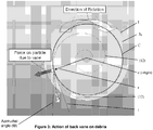
- Figure 3 shows a force (indicated by the associated arrow) that will be acting upon any debris which comes in contact with the rear spiral-shaped vane (12), according to some embodiments of the present invention.
- This force will be perpendicular (as shown in Figure 3 ) to the logarithmic spiral-shaped vane (12) which, e.g., due to its construction from the aforementioned equation, will be at the chosen angle, e.g., beta ( ⁇ ), relative to a line T tangent to a circle C centered at the center of the impeller I and drawn at any given radius r at which the debris may come in contact with the logarithmic spiral-shaped vane (12), and extending out to the point of contact between the logarithmic spiral-shaped vane (12) and the debris, consistent with that shown in Figure 3 .
- beta beta
- the impeller I in Figures 2-3 replaces the impeller (2) shown in Figures 1A to 1C for implementing at least one embodiment of the present invention.
- pumps having impellers with spiral-shaped back vanes according to the present invention were able to pass all of the debris through without jamming up and no damage was observed on the back of the impeller or on the motor housing after the testing.
- pumps e.g., like that disclosed in relation to Figures 2-3 , appear to provide an important improvement over pumps, e.g., like that shown in Figures 1A to 1C .
- a logarithmic spiral, equiangular spiral or growth spiral is a self-similar spiral curve, e.g., which often appears in nature.
- a self-similar object is generally understood to be exactly or approximately similar to a part of itself (i.e. the whole has the same shape as one or more of the parts);
- a spiral is generally understood to be a curve (i.e., non-straight line) which emanates from a central point, getting progressively farther away as the curve revolves around the central point;
- a curve also called a curved line
- Figures 4-8 shows diagrams related to a computational fluids dynamics (CFD) simulation that was conducted of sand penetration into a gap between an impeller outer hub wall and a volute hub wall.
- CFD computational fluids dynamics
- two pump geometries were analyzed: a case 1 for a pump geometery without a back vane impeller,and a case 2 for a pump geometry with a back vane (e.g., 10 degree angle).
- a Fluent 14.5 code was used, and a turbulence k-w SST model was used with conditions, as follows:
- Figure 4 shows a pump P having a pump housing PH, an inlet and an outlet, along with a plane section labelled A-A, indicated for the purpose of discussing results of the CFD simulation of sand penetration into a gap between an impeller outer hub wall and a volute hub wall.
- the impeller is shown in the form of a white outline (no grey scale shading) and outlined by the grey scale shading.
- the spiral-shaped vane is indicated by four arrows labeled (12).
- arrows shown the direction of NRV are shown, labeled accordingly and point towards the center or axis of the impeller labeled I.
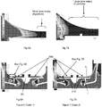
- Figs. 6A, 6B, and Figs. 7A, and 7B show sand concentration in the gap between the impeller outer hub wall and the volute hub wall on section A-A section in Figure 4 for easel and case2 respectively.
- Fig.6B is the amplification zone of the highlighted oval or eliptical region in the Fig.6A; and Fig.7B is the amplification zone of the highlighted oval or eliptical region in the Fig. 7b .
- Figs. 6B and Fig. 7B the areas empty of sand particles are indicated by associated braces and textual labeling.
- the clear difference between the size of the areas empty of sand particles in Figs. 6B and 7B indicates that the back vane (case 2) prevents the penetration and concentration of more sand particles into the gap between the impeller outer hub wall and the volute hub wall.
- Figs. 8A and 8B shows traces of particles, e.g., including in the gap between the impeller outer hub wall and the volute hub wall on section A-A section in Figure 4 for case 1 and case 2 respectively.
- the particle traces are indicated by grey scale shading and traced by particles residence time.
- the CFD simulation included about 900 particles total.
- Fig. 8A shows and indicates particles that penetrated into the gap between the impeller outer hub wall and the volute hub wall for case 1 (without the spiral-shaped back vane).
- Fig. 8B shows and indicates no particles that penetrated into the gap between the impeller outer hub wall and the volute hub wall for case 2 (with the spiral-shaped back vane).
- centrifugal pump which uses an impeller and may be used in liquid containing debris.
- the present invention may also be used in, or form part of, or used in conjunction with, any fluid handling application.
- the scope of the invention is also not intended to be limited to being implemented in any particular type or kind of pump either now known or later developed in the future, and may include centrifugal pumps, etc.
Landscapes
- Engineering & Computer Science (AREA)
- Mechanical Engineering (AREA)
- General Engineering & Computer Science (AREA)
- Physics & Mathematics (AREA)
- Geometry (AREA)
- Structures Of Non-Positive Displacement Pumps (AREA)
Claims (6)
- Vorrichtung mit einer Pumpe (P) zum Pumpen einer Flüssigkeit, die Schmutz enthält, umfassend ein Flügelrad (2), das als eine rotierende Scheibe ausgebildet ist, welche eine Vorderseite und eine Rückseite (11) umfasst, wobei das Flügelrad (2) drehbar auf einer Welle (6) angeordnet ist, wobei sich die Vorderseite in unmittelbarer Nähe eines Einlasses (1) befindet, der die zu pumpende Flüssigkeit aufnimmt, und die Rückseite (11) in unmittelbarer Nähe eines Motorgehäuses (9), in dem ein Motor (5) und die Welle (6) untergebracht sind, so dass eine Hauptströmung (7) der zu pumpenden Flüssigkeit und in einem Bereich zwischen der Rückseite (11) des Flügelrads (2) und dem Motorgehäuse (9) eine rückseitige Flügelrad-Strömung (8) der zu pumpenden Flüssigkeit bereitgestellt werden, dadurch gekennzeichnet, dass die Rückseite (11) eine logarithmisch-spiralförmige Schaufel (12) umfasst, die dazu dient, aus dem Bereich zwischen der Rückseite (11) des Flügelrads (2) und dem Motorgehäuse (9) kontinuierlich Schmutz zu schaufeln und auszustoßen, wobei die logarithmisch-spiralförmige Schaufel (12) als ein Bogen ausgebildet ist, der in einem Mittelpunkt oder einer Achse (c) des Flügelrads (2) seinen Ursprung hat und sich von dem Mittelpunkt oder der Achse (c) schrittweise weg erstreckt, während sich der Bogen (12) mindestens eine ganze Umdrehung um den Mittelpunkt oder die Achse (c) dreht, wobei sich das Flügelrad in einer Drehrichtung um den Mittelpunkt oder die Achse (c) dreht und die logarithmisch-spiralförmige Schaufel (12) eine Spirale aufweist, die in dem Mittelpunkt oder der Achse (c) ihren Ursprung hat und sich von dem Mittelpunkt oder der Achse (c) in einer zu der Drehrichtung entgegengesetzten Richtung schrittweise weg krümmt.
- Vorrichtung nach Anspruch 1, wobei die logarithmisch-spiralförmige Schaufel (12) eine logarithmisch-spiralförmige Schaufel (12) ist, die im Wesentlichen durch folgende Gleichung definiert ist:

der Parameter Beta (β) ein Winkel zwischen einer Linientangente (T) zu einem im Mittelpunkt oder an der Achse (c) des Flügelrads (2) zentrierten und mit einem beliebigen Radius (r) bis zu einem Auftreffpunkt, an dem der Schmutz mit der logarithmisch-spiralförmigen Schaufel (12) in Kontakt kommen kann, gezogenen Kreis (C) einerseits und einer Tangente zu der logarithmisch-spiralförmigen Schaufel (12) an dem Auftreffpunkt andererseits ist. - Vorrichtung nach Anspruch 1 oder 2, wobei die Vorderseite eine oder mehrere Schaufeln (10) umfasst, die dazu dienen, eine Kraft von dem Motor (5) auf die gepumpte Flüssigkeit zu übertragen, wodurch die Flüssigkeit fließt.
- Vorrichtung nach einem der Ansprüche 1 bis 3, wobei die Pumpe (P) Folgendes umfasst:
ein Pumpengehäuse (PH; 20) mit einem Einlass (1) und einem Auslass (4), um die zu pumpende Flüssigkeit durch die Hauptströmung (7) bereitzustellen; wobei das Motorgehäuse (9) in dem Pumpengehäuse (PH; 20) untergebracht ist. - Vorrichtung nach einem der Ansprüche 1 bis 4, wobei die Pumpe (P) eine Kreiselpumpe ist.
- Vorrichtung nach einem der Ansprüche 1 bis 5, wobei die logarithmisch-spiralförmige Schaufel (12) einen einzigen Bogen umfasst, der in dem Mittelpunkt oder der Achse (c) des Flügelrads (2) seinen Ursprung hat und sich schrittweise weg erstreckt, während sich der der Bogen (12) um mehr als das 1½-fache (mehr als 540°) um den Mittelpunkt oder die Achse (c) dreht.
Applications Claiming Priority (2)
| Application Number | Priority Date | Filing Date | Title |
|---|---|---|---|
| US201361837753P | 2013-06-21 | 2013-06-21 | |
| PCT/US2014/043660 WO2014205439A1 (en) | 2013-06-21 | 2014-06-23 | Debris removing impeller backvane |
Publications (3)
| Publication Number | Publication Date |
|---|---|
| EP3011186A1 EP3011186A1 (de) | 2016-04-27 |
| EP3011186A4 EP3011186A4 (de) | 2017-02-15 |
| EP3011186B1 true EP3011186B1 (de) | 2020-12-30 |
Family
ID=52105391
Family Applications (1)
| Application Number | Title | Priority Date | Filing Date |
|---|---|---|---|
| EP14813765.6A Not-in-force EP3011186B1 (de) | 2013-06-21 | 2014-06-23 | Rückstandsentfernende laufradrückschaufel |
Country Status (7)
| Country | Link |
|---|---|
| US (1) | US10514042B2 (de) |
| EP (1) | EP3011186B1 (de) |
| CN (1) | CN105392998B (de) |
| AU (2) | AU2014284140A1 (de) |
| CA (1) | CA2915631C (de) |
| MX (1) | MX383972B (de) |
| WO (1) | WO2014205439A1 (de) |
Family Cites Families (49)
| Publication number | Priority date | Publication date | Assignee | Title |
|---|---|---|---|---|
| US2028783A (en) | 1935-06-05 | 1936-01-28 | Duriron Co | Centrifugal pump |
| US2245035A (en) | 1939-02-13 | 1941-06-10 | American Well Works | Centrifugal sludge pump |
| US2255287A (en) | 1940-08-12 | 1941-09-09 | Duriron Co | Double vane impeller |
| US2361521A (en) | 1943-11-01 | 1944-10-31 | W S Darley & Company | Centrifugal pump |
| US2882829A (en) * | 1956-02-09 | 1959-04-21 | Fmc Corp | Fabricated impeller for pumps |
| GB1063096A (en) | 1964-05-22 | 1967-03-30 | Ulrich Max Willi Barske | Improvements in and relating to centrifugal pumps |
| AT291003B (de) | 1969-04-28 | 1971-06-25 | Paul Bungartz | Kreiselpumpe mit axialem Eintritt und fliegend gelagertem Laufrad |
| JPS531301A (en) * | 1976-06-28 | 1978-01-09 | Hitachi Ltd | Means for reducing shaft thrust in centrifugal turbo-machine |
| CH627236A5 (de) * | 1978-02-14 | 1981-12-31 | Martin Staehle | |
| US4410337A (en) | 1980-04-07 | 1983-10-18 | A. Ahlstrom Osakeyhtio | Method and an apparatus for separating a gas from a fibre suspension |
| US4538959A (en) | 1982-11-01 | 1985-09-03 | International Telephone & Telegraph Corp. | Clean-in-place pump |
| US4664592A (en) | 1983-07-14 | 1987-05-12 | Warman International Limited | Centrifugal pump impeller configured to limit fluid recirculation |
| FI872967A7 (fi) | 1987-07-06 | 1989-01-07 | Ahlstroem Oy | Pump och foerfarande foer separering av gas med pumpen ur mediet som skall pumpas. |
| DE68928632T2 (de) | 1988-02-26 | 1998-07-30 | Ahlstroem Oy | Verfahren und Vorrichtung zum Behandeln von Faserbrei |
| US4877424A (en) | 1988-02-26 | 1989-10-31 | Markku Perkola | Method and apparatus for separating solids from a solids-gas mixture |
| FI86333C (fi) | 1988-04-11 | 1992-07-10 | Ahlstroem Oy | Foerfarande och anordning foer separering av gas med pumpen ur mediet som skall pumpas. |
| US5167678A (en) | 1988-04-11 | 1992-12-01 | A. Ahlstrom Corporation | Apparatus for separating gas with a pump from a medium being pumped |
| US4981413A (en) | 1989-04-27 | 1991-01-01 | Ahlstrom Corporation | Pump for and method of separating gas from a fluid to be pumped |
| US5116198A (en) | 1990-09-07 | 1992-05-26 | Ahlstrom Corporation | Centrifugal pumping apparatus |
| US5151010A (en) | 1990-09-07 | 1992-09-29 | A. Ahlstrom Corporation | Combined centrifugal and vacuum pump |
| US5078573A (en) | 1990-09-07 | 1992-01-07 | A. Ahlstrom Corporation | Liquid ring pump having tapered blades and housing |
| US5114310A (en) | 1990-09-07 | 1992-05-19 | A. Ahlstrom Corporation | Centrifugal pump with sealing means |
| US5152663A (en) | 1990-09-07 | 1992-10-06 | A. Ahlstrom Corporation | Centrifugal pump |
| SE469040B (sv) | 1991-09-03 | 1993-05-03 | Flygt Ab Itt | Centrifugalpumphjul foer pump avsedd att pumpa vaetskor innehaallande fasta partiklar |
| US5460482A (en) | 1992-05-26 | 1995-10-24 | Vaughan Co., Inc. | Centrifugal chopper pump with internal cutter |
| US5489187A (en) * | 1994-09-06 | 1996-02-06 | Roper Industries, Inc. | Impeller pump with vaned backplate for clearing debris |
| NZ308546A (en) | 1995-06-05 | 1999-07-29 | Ahlstroem Oy | Method of controlling the function of a centrifugal pump and vacuum pump combination, and a gas-separating centrifugal pump |
| US6120252A (en) | 1995-12-27 | 2000-09-19 | Ahlstrom Machinery Corporation | Gas separation control in a centrifugal pump/vacuum pump |
| US6074166A (en) * | 1998-10-01 | 2000-06-13 | Moddemeijer; Pieter J. H. | Pump |
| FI111023B (fi) | 1998-12-30 | 2003-05-15 | Sulzer Pumpen Ag | Menetelmä ja laite materiaalin pumppaamiseksi sekä laitteen yhteydessä käytettävä roottori |
| US6190121B1 (en) | 1999-02-12 | 2001-02-20 | Hayward Gordon Limited | Centrifugal pump with solids cutting action |
| AU8001100A (en) | 1999-10-06 | 2001-05-10 | Vaughan Co., Inc. | Centrifugal pump improvements |
| JP2003269378A (ja) * | 2002-03-14 | 2003-09-25 | San Medical Gijutsu Kenkyusho:Kk | 遠心ポンプ |
| DE20221438U1 (de) | 2002-05-02 | 2005-12-08 | Schmalenberger Gmbh & Co. Kg | Kreiselpumpe |
| US7008177B2 (en) * | 2002-11-14 | 2006-03-07 | Cummins Inc. | Centrifugal pump with self cooling and flushing features |
| US7080797B2 (en) | 2003-06-27 | 2006-07-25 | Envirotech Pumpsystems, Inc. | Pump impeller and chopper plate for a centrifugal pump |
| DE502004006266D1 (de) | 2003-08-04 | 2008-04-03 | Sulzer Pumpen Ag | Laufrad für pumpen |
| SE0302752L (sv) * | 2003-10-20 | 2005-02-15 | Itt Mfg Enterprises Inc | Centrifugalpump |
| JP2005214099A (ja) * | 2004-01-30 | 2005-08-11 | Asmo Co Ltd | 流体ポンプ |
| SE0402840L (sv) * | 2004-11-19 | 2006-04-11 | Itt Mfg Enterprises Inc | Pumphjul |
| US7159806B1 (en) * | 2005-01-18 | 2007-01-09 | Ritsema Stephen T | Cutter assembly for a grinder pump |
| SE0501382L (sv) | 2005-06-17 | 2006-06-13 | Itt Mfg Enterprises Inc | Pump för pumpning av förorenad vätska |
| US8105017B2 (en) | 2008-07-29 | 2012-01-31 | Vaughan Co., Inc. | Centrifugal chopper pump with impeller assembly |
| US8221070B2 (en) | 2009-03-25 | 2012-07-17 | Woodward, Inc. | Centrifugal impeller with controlled force balance |
| CN101691873B (zh) | 2009-10-12 | 2012-06-27 | 台州豪贝泵业有限公司 | 一种泵用开式叶轮 |
| DK177190B1 (en) | 2010-05-03 | 2012-05-21 | Alfa Laval Corp Ab | Centrifugal pumpe |
| WO2012009021A2 (en) | 2010-07-16 | 2012-01-19 | Enviro Tech Pumpsystems, Inc. | Apparatus for non-clogging pumps |
| AU2011281111B2 (en) | 2010-07-21 | 2015-03-26 | Itt Manufacturing Enterprises Llc | Wear reduction device for rotary solids handling equipment |
| CN102661282A (zh) | 2012-04-16 | 2012-09-12 | 杭州萧山美特轻工机械有限公司 | 开式螺旋纸浆泵 |
-
2014
- 2014-06-23 EP EP14813765.6A patent/EP3011186B1/de not_active Not-in-force
- 2014-06-23 MX MX2015017465A patent/MX383972B/es unknown
- 2014-06-23 US US14/899,894 patent/US10514042B2/en active Active
- 2014-06-23 CA CA2915631A patent/CA2915631C/en active Active
- 2014-06-23 AU AU2014284140A patent/AU2014284140A1/en not_active Abandoned
- 2014-06-23 WO PCT/US2014/043660 patent/WO2014205439A1/en not_active Ceased
- 2014-06-23 CN CN201480041237.2A patent/CN105392998B/zh active Active
-
2018
- 2018-02-15 AU AU2018201107A patent/AU2018201107B2/en not_active Ceased
Non-Patent Citations (1)
| Title |
|---|
| None * |
Also Published As
| Publication number | Publication date |
|---|---|
| WO2014205439A1 (en) | 2014-12-24 |
| EP3011186A1 (de) | 2016-04-27 |
| AU2014284140A1 (en) | 2016-01-21 |
| US10514042B2 (en) | 2019-12-24 |
| CN105392998A (zh) | 2016-03-09 |
| AU2018201107B2 (en) | 2019-11-21 |
| MX383972B (es) | 2025-03-14 |
| CN105392998B (zh) | 2019-09-13 |
| EP3011186A4 (de) | 2017-02-15 |
| CA2915631A1 (en) | 2014-12-24 |
| CA2915631C (en) | 2020-06-02 |
| AU2018201107A1 (en) | 2018-03-08 |
| US20160138605A1 (en) | 2016-05-19 |
Similar Documents
| Publication | Publication Date | Title |
|---|---|---|
| Binama et al. | Cavitation effects in centrifugal pumps-A review | |
| US9689402B2 (en) | Centrifugal pump impellor with novel balancing holes that improve pump efficiency | |
| NO20121328A1 (no) | Løpehjul for sentrifugalpumpe samt anvendelse derav ved pumping av borevæske inneholdende borekaks | |
| EP1536143B1 (de) | Sauglaufrad und damit ausgestattete pumpe | |
| EP1284368A2 (de) | Verschleissverringerndeumlenkung für eine Dickstoffpumpe | |
| CN105003458A (zh) | 用于离心泵的叶轮、离心泵及其使用 | |
| Jani et al. | An overview on cavitation in centrifugal pump | |
| EP3011186B1 (de) | Rückstandsentfernende laufradrückschaufel | |
| KR101070136B1 (ko) | 원통형 베인을 포함하는 임펠러 | |
| KR102752663B1 (ko) | 이물질 커팅기능이 구비된 축사류 펌프 | |
| CA2957279C (en) | Impeller with axially curving vane extensions to prevent airlock | |
| US6752597B2 (en) | Duplex shear force rotor | |
| CN204061305U (zh) | 流体泵浦低紊流动叶轮 | |
| Dzhurabekov et al. | Improving impeller and water flow section of vane pumps | |
| CN111201378A (zh) | 用于污水泵的叶轮 | |
| BURGREEN et al. | A computational and experimental comparison of two outlet stators for the Nimbus LVAD | |
| CN102345630B (zh) | 泵用叶轮以及泵 | |
| JP6758924B2 (ja) | 羽根車 | |
| JP6768428B2 (ja) | 先行待機運転ポンプ | |
| CN106321518A (zh) | 一种防止颗粒进入密封装置的离心泵泵盖 | |
| JP6700660B2 (ja) | 回転軸機構およびポンプ | |
| EP3732378A1 (de) | Pumpe | |
| Feng et al. | Experimental Investigation on Turbulence Fields in a Radial Diffuser Pump Using PIV Technique. | |
| Tanaka et al. | An Investigation on Velocity Triangle Applied to Fluid Particle at Rotating Flow Passage of Impeller Blade in Centrifugal Pump | |
| RU2239725C2 (ru) | Центробежный насос |
Legal Events
| Date | Code | Title | Description |
|---|---|---|---|
| PUAI | Public reference made under article 153(3) epc to a published international application that has entered the european phase |
Free format text: ORIGINAL CODE: 0009012 |
|
| 17P | Request for examination filed |
Effective date: 20151221 |
|
| AK | Designated contracting states |
Kind code of ref document: A1 Designated state(s): AL AT BE BG CH CY CZ DE DK EE ES FI FR GB GR HR HU IE IS IT LI LT LU LV MC MK MT NL NO PL PT RO RS SE SI SK SM TR |
|
| AX | Request for extension of the european patent |
Extension state: BA ME |
|
| DAX | Request for extension of the european patent (deleted) | ||
| A4 | Supplementary search report drawn up and despatched |
Effective date: 20170118 |
|
| RIC1 | Information provided on ipc code assigned before grant |
Ipc: F04D 29/22 20060101AFI20170111BHEP Ipc: F04D 7/04 20060101ALI20170111BHEP Ipc: F04D 29/24 20060101ALI20170111BHEP |
|
| STAA | Information on the status of an ep patent application or granted ep patent |
Free format text: STATUS: EXAMINATION IS IN PROGRESS |
|
| 17Q | First examination report despatched |
Effective date: 20180525 |
|
| REG | Reference to a national code |
Ref country code: DE Ref legal event code: R079 Ref document number: 602014073843 Country of ref document: DE Free format text: PREVIOUS MAIN CLASS: F04D0029240000 Ipc: F04D0029220000 |
|
| GRAP | Despatch of communication of intention to grant a patent |
Free format text: ORIGINAL CODE: EPIDOSNIGR1 |
|
| STAA | Information on the status of an ep patent application or granted ep patent |
Free format text: STATUS: GRANT OF PATENT IS INTENDED |
|
| RIC1 | Information provided on ipc code assigned before grant |
Ipc: F04D 29/10 20060101ALN20200629BHEP Ipc: F04D 29/22 20060101AFI20200629BHEP Ipc: F04D 29/70 20060101ALN20200629BHEP Ipc: F04D 29/24 20060101ALI20200629BHEP Ipc: F04D 7/04 20060101ALI20200629BHEP |
|
| INTG | Intention to grant announced |
Effective date: 20200723 |
|
| GRAS | Grant fee paid |
Free format text: ORIGINAL CODE: EPIDOSNIGR3 |
|
| GRAA | (expected) grant |
Free format text: ORIGINAL CODE: 0009210 |
|
| STAA | Information on the status of an ep patent application or granted ep patent |
Free format text: STATUS: THE PATENT HAS BEEN GRANTED |
|
| AK | Designated contracting states |
Kind code of ref document: B1 Designated state(s): AL AT BE BG CH CY CZ DE DK EE ES FI FR GB GR HR HU IE IS IT LI LT LU LV MC MK MT NL NO PL PT RO RS SE SI SK SM TR |
|
| REG | Reference to a national code |
Ref country code: GB Ref legal event code: FG4D |
|
| REG | Reference to a national code |
Ref country code: DE Ref legal event code: R096 Ref document number: 602014073843 Country of ref document: DE |
|
| REG | Reference to a national code |
Ref country code: AT Ref legal event code: REF Ref document number: 1350208 Country of ref document: AT Kind code of ref document: T Effective date: 20210115 |
|
| REG | Reference to a national code |
Ref country code: IE Ref legal event code: FG4D |
|
| PG25 | Lapsed in a contracting state [announced via postgrant information from national office to epo] |
Ref country code: GR Free format text: LAPSE BECAUSE OF FAILURE TO SUBMIT A TRANSLATION OF THE DESCRIPTION OR TO PAY THE FEE WITHIN THE PRESCRIBED TIME-LIMIT Effective date: 20210331 Ref country code: NO Free format text: LAPSE BECAUSE OF FAILURE TO SUBMIT A TRANSLATION OF THE DESCRIPTION OR TO PAY THE FEE WITHIN THE PRESCRIBED TIME-LIMIT Effective date: 20210330 Ref country code: FI Free format text: LAPSE BECAUSE OF FAILURE TO SUBMIT A TRANSLATION OF THE DESCRIPTION OR TO PAY THE FEE WITHIN THE PRESCRIBED TIME-LIMIT Effective date: 20201230 Ref country code: RS Free format text: LAPSE BECAUSE OF FAILURE TO SUBMIT A TRANSLATION OF THE DESCRIPTION OR TO PAY THE FEE WITHIN THE PRESCRIBED TIME-LIMIT Effective date: 20201230 |
|
| REG | Reference to a national code |
Ref country code: AT Ref legal event code: MK05 Ref document number: 1350208 Country of ref document: AT Kind code of ref document: T Effective date: 20201230 |
|
| PG25 | Lapsed in a contracting state [announced via postgrant information from national office to epo] |
Ref country code: BG Free format text: LAPSE BECAUSE OF FAILURE TO SUBMIT A TRANSLATION OF THE DESCRIPTION OR TO PAY THE FEE WITHIN THE PRESCRIBED TIME-LIMIT Effective date: 20210330 Ref country code: LV Free format text: LAPSE BECAUSE OF FAILURE TO SUBMIT A TRANSLATION OF THE DESCRIPTION OR TO PAY THE FEE WITHIN THE PRESCRIBED TIME-LIMIT Effective date: 20201230 Ref country code: SE Free format text: LAPSE BECAUSE OF FAILURE TO SUBMIT A TRANSLATION OF THE DESCRIPTION OR TO PAY THE FEE WITHIN THE PRESCRIBED TIME-LIMIT Effective date: 20201230 |
|
| REG | Reference to a national code |
Ref country code: NL Ref legal event code: MP Effective date: 20201230 |
|
| PG25 | Lapsed in a contracting state [announced via postgrant information from national office to epo] |
Ref country code: HR Free format text: LAPSE BECAUSE OF FAILURE TO SUBMIT A TRANSLATION OF THE DESCRIPTION OR TO PAY THE FEE WITHIN THE PRESCRIBED TIME-LIMIT Effective date: 20201230 |
|
| REG | Reference to a national code |
Ref country code: LT Ref legal event code: MG9D |
|
| PG25 | Lapsed in a contracting state [announced via postgrant information from national office to epo] |
Ref country code: LT Free format text: LAPSE BECAUSE OF FAILURE TO SUBMIT A TRANSLATION OF THE DESCRIPTION OR TO PAY THE FEE WITHIN THE PRESCRIBED TIME-LIMIT Effective date: 20201230 Ref country code: PT Free format text: LAPSE BECAUSE OF FAILURE TO SUBMIT A TRANSLATION OF THE DESCRIPTION OR TO PAY THE FEE WITHIN THE PRESCRIBED TIME-LIMIT Effective date: 20210430 Ref country code: RO Free format text: LAPSE BECAUSE OF FAILURE TO SUBMIT A TRANSLATION OF THE DESCRIPTION OR TO PAY THE FEE WITHIN THE PRESCRIBED TIME-LIMIT Effective date: 20201230 Ref country code: SK Free format text: LAPSE BECAUSE OF FAILURE TO SUBMIT A TRANSLATION OF THE DESCRIPTION OR TO PAY THE FEE WITHIN THE PRESCRIBED TIME-LIMIT Effective date: 20201230 Ref country code: CZ Free format text: LAPSE BECAUSE OF FAILURE TO SUBMIT A TRANSLATION OF THE DESCRIPTION OR TO PAY THE FEE WITHIN THE PRESCRIBED TIME-LIMIT Effective date: 20201230 Ref country code: EE Free format text: LAPSE BECAUSE OF FAILURE TO SUBMIT A TRANSLATION OF THE DESCRIPTION OR TO PAY THE FEE WITHIN THE PRESCRIBED TIME-LIMIT Effective date: 20201230 Ref country code: NL Free format text: LAPSE BECAUSE OF FAILURE TO SUBMIT A TRANSLATION OF THE DESCRIPTION OR TO PAY THE FEE WITHIN THE PRESCRIBED TIME-LIMIT Effective date: 20201230 |
|
| PG25 | Lapsed in a contracting state [announced via postgrant information from national office to epo] |
Ref country code: PL Free format text: LAPSE BECAUSE OF FAILURE TO SUBMIT A TRANSLATION OF THE DESCRIPTION OR TO PAY THE FEE WITHIN THE PRESCRIBED TIME-LIMIT Effective date: 20201230 Ref country code: AT Free format text: LAPSE BECAUSE OF FAILURE TO SUBMIT A TRANSLATION OF THE DESCRIPTION OR TO PAY THE FEE WITHIN THE PRESCRIBED TIME-LIMIT Effective date: 20201230 |
|
| PG25 | Lapsed in a contracting state [announced via postgrant information from national office to epo] |
Ref country code: IS Free format text: LAPSE BECAUSE OF FAILURE TO SUBMIT A TRANSLATION OF THE DESCRIPTION OR TO PAY THE FEE WITHIN THE PRESCRIBED TIME-LIMIT Effective date: 20210430 |
|
| REG | Reference to a national code |
Ref country code: DE Ref legal event code: R097 Ref document number: 602014073843 Country of ref document: DE |
|
| PG25 | Lapsed in a contracting state [announced via postgrant information from national office to epo] |
Ref country code: AL Free format text: LAPSE BECAUSE OF FAILURE TO SUBMIT A TRANSLATION OF THE DESCRIPTION OR TO PAY THE FEE WITHIN THE PRESCRIBED TIME-LIMIT Effective date: 20201230 Ref country code: IT Free format text: LAPSE BECAUSE OF FAILURE TO SUBMIT A TRANSLATION OF THE DESCRIPTION OR TO PAY THE FEE WITHIN THE PRESCRIBED TIME-LIMIT Effective date: 20201230 |
|
| PLBE | No opposition filed within time limit |
Free format text: ORIGINAL CODE: 0009261 |
|
| STAA | Information on the status of an ep patent application or granted ep patent |
Free format text: STATUS: NO OPPOSITION FILED WITHIN TIME LIMIT |
|
| PG25 | Lapsed in a contracting state [announced via postgrant information from national office to epo] |
Ref country code: DK Free format text: LAPSE BECAUSE OF FAILURE TO SUBMIT A TRANSLATION OF THE DESCRIPTION OR TO PAY THE FEE WITHIN THE PRESCRIBED TIME-LIMIT Effective date: 20201230 Ref country code: ES Free format text: LAPSE BECAUSE OF FAILURE TO SUBMIT A TRANSLATION OF THE DESCRIPTION OR TO PAY THE FEE WITHIN THE PRESCRIBED TIME-LIMIT Effective date: 20201230 |
|
| 26N | No opposition filed |
Effective date: 20211001 |
|
| REG | Reference to a national code |
Ref country code: DE Ref legal event code: R119 Ref document number: 602014073843 Country of ref document: DE |
|
| PG25 | Lapsed in a contracting state [announced via postgrant information from national office to epo] |
Ref country code: MC Free format text: LAPSE BECAUSE OF FAILURE TO SUBMIT A TRANSLATION OF THE DESCRIPTION OR TO PAY THE FEE WITHIN THE PRESCRIBED TIME-LIMIT Effective date: 20201230 |
|
| REG | Reference to a national code |
Ref country code: CH Ref legal event code: PL |
|
| GBPC | Gb: european patent ceased through non-payment of renewal fee |
Effective date: 20210623 |
|
| PG25 | Lapsed in a contracting state [announced via postgrant information from national office to epo] |
Ref country code: SI Free format text: LAPSE BECAUSE OF FAILURE TO SUBMIT A TRANSLATION OF THE DESCRIPTION OR TO PAY THE FEE WITHIN THE PRESCRIBED TIME-LIMIT Effective date: 20201230 |
|
| REG | Reference to a national code |
Ref country code: BE Ref legal event code: MM Effective date: 20210630 |
|
| PG25 | Lapsed in a contracting state [announced via postgrant information from national office to epo] |
Ref country code: LU Free format text: LAPSE BECAUSE OF NON-PAYMENT OF DUE FEES Effective date: 20210623 |
|
| PG25 | Lapsed in a contracting state [announced via postgrant information from national office to epo] |
Ref country code: LI Free format text: LAPSE BECAUSE OF NON-PAYMENT OF DUE FEES Effective date: 20210630 Ref country code: IE Free format text: LAPSE BECAUSE OF NON-PAYMENT OF DUE FEES Effective date: 20210623 Ref country code: GB Free format text: LAPSE BECAUSE OF NON-PAYMENT OF DUE FEES Effective date: 20210623 Ref country code: DE Free format text: LAPSE BECAUSE OF NON-PAYMENT OF DUE FEES Effective date: 20220101 Ref country code: CH Free format text: LAPSE BECAUSE OF NON-PAYMENT OF DUE FEES Effective date: 20210630 |
|
| PG25 | Lapsed in a contracting state [announced via postgrant information from national office to epo] |
Ref country code: IS Free format text: LAPSE BECAUSE OF FAILURE TO SUBMIT A TRANSLATION OF THE DESCRIPTION OR TO PAY THE FEE WITHIN THE PRESCRIBED TIME-LIMIT Effective date: 20210430 Ref country code: FR Free format text: LAPSE BECAUSE OF NON-PAYMENT OF DUE FEES Effective date: 20210630 |
|
| PG25 | Lapsed in a contracting state [announced via postgrant information from national office to epo] |
Ref country code: BE Free format text: LAPSE BECAUSE OF NON-PAYMENT OF DUE FEES Effective date: 20210630 |
|
| PG25 | Lapsed in a contracting state [announced via postgrant information from national office to epo] |
Ref country code: HU Free format text: LAPSE BECAUSE OF FAILURE TO SUBMIT A TRANSLATION OF THE DESCRIPTION OR TO PAY THE FEE WITHIN THE PRESCRIBED TIME-LIMIT; INVALID AB INITIO Effective date: 20140623 |
|
| PG25 | Lapsed in a contracting state [announced via postgrant information from national office to epo] |
Ref country code: CY Free format text: LAPSE BECAUSE OF FAILURE TO SUBMIT A TRANSLATION OF THE DESCRIPTION OR TO PAY THE FEE WITHIN THE PRESCRIBED TIME-LIMIT Effective date: 20201230 |
|
| PG25 | Lapsed in a contracting state [announced via postgrant information from national office to epo] |
Ref country code: SM Free format text: LAPSE BECAUSE OF FAILURE TO SUBMIT A TRANSLATION OF THE DESCRIPTION OR TO PAY THE FEE WITHIN THE PRESCRIBED TIME-LIMIT Effective date: 20201230 |
|
| PG25 | Lapsed in a contracting state [announced via postgrant information from national office to epo] |
Ref country code: MK Free format text: LAPSE BECAUSE OF FAILURE TO SUBMIT A TRANSLATION OF THE DESCRIPTION OR TO PAY THE FEE WITHIN THE PRESCRIBED TIME-LIMIT Effective date: 20201230 |
|
| PG25 | Lapsed in a contracting state [announced via postgrant information from national office to epo] |
Ref country code: TR Free format text: LAPSE BECAUSE OF FAILURE TO SUBMIT A TRANSLATION OF THE DESCRIPTION OR TO PAY THE FEE WITHIN THE PRESCRIBED TIME-LIMIT Effective date: 20201230 |
|
| PG25 | Lapsed in a contracting state [announced via postgrant information from national office to epo] |
Ref country code: MT Free format text: LAPSE BECAUSE OF FAILURE TO SUBMIT A TRANSLATION OF THE DESCRIPTION OR TO PAY THE FEE WITHIN THE PRESCRIBED TIME-LIMIT Effective date: 20201230 |