EP3011232B1 - Luftvorhangvorrichtung zur messung eines temperaturprofils und verfahren dafür - Google Patents
Luftvorhangvorrichtung zur messung eines temperaturprofils und verfahren dafür Download PDFInfo
- Publication number
- EP3011232B1 EP3011232B1 EP14727956.6A EP14727956A EP3011232B1 EP 3011232 B1 EP3011232 B1 EP 3011232B1 EP 14727956 A EP14727956 A EP 14727956A EP 3011232 B1 EP3011232 B1 EP 3011232B1
- Authority
- EP
- European Patent Office
- Prior art keywords
- air curtain
- temperature profile
- air
- sensor
- length
- Prior art date
- Legal status (The legal status is an assumption and is not a legal conclusion. Google has not performed a legal analysis and makes no representation as to the accuracy of the status listed.)
- Active
Links
Images

Classifications
-
- F—MECHANICAL ENGINEERING; LIGHTING; HEATING; WEAPONS; BLASTING
- F24—HEATING; RANGES; VENTILATING
- F24F—AIR-CONDITIONING; AIR-HUMIDIFICATION; VENTILATION; USE OF AIR CURRENTS FOR SCREENING
- F24F9/00—Use of air currents for screening, e.g. air curtains
-
- F—MECHANICAL ENGINEERING; LIGHTING; HEATING; WEAPONS; BLASTING
- F24—HEATING; RANGES; VENTILATING
- F24F—AIR-CONDITIONING; AIR-HUMIDIFICATION; VENTILATION; USE OF AIR CURRENTS FOR SCREENING
- F24F11/00—Control or safety arrangements
-
- F—MECHANICAL ENGINEERING; LIGHTING; HEATING; WEAPONS; BLASTING
- F24—HEATING; RANGES; VENTILATING
- F24F—AIR-CONDITIONING; AIR-HUMIDIFICATION; VENTILATION; USE OF AIR CURRENTS FOR SCREENING
- F24F11/00—Control or safety arrangements
- F24F11/30—Control or safety arrangements for purposes related to the operation of the system, e.g. for safety or monitoring
-
- F—MECHANICAL ENGINEERING; LIGHTING; HEATING; WEAPONS; BLASTING
- F24—HEATING; RANGES; VENTILATING
- F24F—AIR-CONDITIONING; AIR-HUMIDIFICATION; VENTILATION; USE OF AIR CURRENTS FOR SCREENING
- F24F11/00—Control or safety arrangements
- F24F11/30—Control or safety arrangements for purposes related to the operation of the system, e.g. for safety or monitoring
- F24F11/46—Improving electric energy efficiency or saving
-
- F—MECHANICAL ENGINEERING; LIGHTING; HEATING; WEAPONS; BLASTING
- F24—HEATING; RANGES; VENTILATING
- F24F—AIR-CONDITIONING; AIR-HUMIDIFICATION; VENTILATION; USE OF AIR CURRENTS FOR SCREENING
- F24F11/00—Control or safety arrangements
- F24F11/70—Control systems characterised by their outputs; Constructional details thereof
- F24F11/72—Control systems characterised by their outputs; Constructional details thereof for controlling the supply of treated air, e.g. its pressure
- F24F11/74—Control systems characterised by their outputs; Constructional details thereof for controlling the supply of treated air, e.g. its pressure for controlling air flow rate or air velocity
- F24F11/76—Control systems characterised by their outputs; Constructional details thereof for controlling the supply of treated air, e.g. its pressure for controlling air flow rate or air velocity by means responsive to temperature, e.g. bimetal springs
-
- F—MECHANICAL ENGINEERING; LIGHTING; HEATING; WEAPONS; BLASTING
- F24—HEATING; RANGES; VENTILATING
- F24F—AIR-CONDITIONING; AIR-HUMIDIFICATION; VENTILATION; USE OF AIR CURRENTS FOR SCREENING
- F24F11/00—Control or safety arrangements
- F24F11/70—Control systems characterised by their outputs; Constructional details thereof
- F24F11/72—Control systems characterised by their outputs; Constructional details thereof for controlling the supply of treated air, e.g. its pressure
- F24F11/74—Control systems characterised by their outputs; Constructional details thereof for controlling the supply of treated air, e.g. its pressure for controlling air flow rate or air velocity
- F24F11/77—Control systems characterised by their outputs; Constructional details thereof for controlling the supply of treated air, e.g. its pressure for controlling air flow rate or air velocity by controlling the speed of ventilators
-
- F—MECHANICAL ENGINEERING; LIGHTING; HEATING; WEAPONS; BLASTING
- F24—HEATING; RANGES; VENTILATING
- F24F—AIR-CONDITIONING; AIR-HUMIDIFICATION; VENTILATION; USE OF AIR CURRENTS FOR SCREENING
- F24F11/00—Control or safety arrangements
- F24F11/70—Control systems characterised by their outputs; Constructional details thereof
- F24F11/72—Control systems characterised by their outputs; Constructional details thereof for controlling the supply of treated air, e.g. its pressure
- F24F11/79—Control systems characterised by their outputs; Constructional details thereof for controlling the supply of treated air, e.g. its pressure for controlling the direction of the supplied air
-
- F—MECHANICAL ENGINEERING; LIGHTING; HEATING; WEAPONS; BLASTING
- F24—HEATING; RANGES; VENTILATING
- F24F—AIR-CONDITIONING; AIR-HUMIDIFICATION; VENTILATION; USE OF AIR CURRENTS FOR SCREENING
- F24F9/00—Use of air currents for screening, e.g. air curtains
- F24F2009/002—Room dividers
-
- F—MECHANICAL ENGINEERING; LIGHTING; HEATING; WEAPONS; BLASTING
- F24—HEATING; RANGES; VENTILATING
- F24F—AIR-CONDITIONING; AIR-HUMIDIFICATION; VENTILATION; USE OF AIR CURRENTS FOR SCREENING
- F24F9/00—Use of air currents for screening, e.g. air curtains
- F24F2009/005—Use of air currents for screening, e.g. air curtains combined with a door
-
- F—MECHANICAL ENGINEERING; LIGHTING; HEATING; WEAPONS; BLASTING
- F24—HEATING; RANGES; VENTILATING
- F24F—AIR-CONDITIONING; AIR-HUMIDIFICATION; VENTILATION; USE OF AIR CURRENTS FOR SCREENING
- F24F2110/00—Control inputs relating to air properties
- F24F2110/10—Temperature
-
- F—MECHANICAL ENGINEERING; LIGHTING; HEATING; WEAPONS; BLASTING
- F24—HEATING; RANGES; VENTILATING
- F24F—AIR-CONDITIONING; AIR-HUMIDIFICATION; VENTILATION; USE OF AIR CURRENTS FOR SCREENING
- F24F2120/00—Control inputs relating to users or occupants
- F24F2120/10—Occupancy
Definitions
- the present invention relates to an air curtain device for providing an air curtain. More specifically, the invention relates to an air curtain preferably with a substantially vertical air flow. Such an air curtain device is usually provided in or close to an opening, in particular a door opening.
- Known air curtain devices provide an air curtain in or close to an opening in a wall to minimize leakage, energy losses and discomfort for people.
- These air curtains are often provided in door openings with different climate conditions on both sides of the opening. These climate conditions may include temperature and humidity.
- climate conditions may include temperature and humidity.
- Several external factors influence the quality of the air curtain that is produced by the air curtain device. Such factors may include wind, wind direction, and sun. However, these factors influence the quality of the air curtain such that the air curtain is in most cases overdimensioned and uses too much energy, or does not perform optimally such that leakages and energy losses are not fully prevented. This results in a not fully effective air curtain.
- the present invention has for its object to provide an air curtain device for realizing an air curtain that is more effective in a broad range of conditions and disturbances, and wholly or partially obviates the abovestated drawbacks, such that a desired air curtain quality is achieved.
- the present invention provides for this purpose an air curtain device for providing an air curtain in or close to an opening in a wall according to claim 1 and a method for producing an air curtain in or close to an opening in a wall according to claim 10.
- the housing of the air curtain device according to the invention comprises air displacing means, comprising for instance one or more fans. Air is supplied via an air inlet. In most cases this air inlet is situated in the immediate vicinity of the position where the air curtain is realized and used, although the air inlet channels can be provided at other positions such that air is transported to the desired position. If desired, a plurality of air inlet channels can be provided.
- the air curtain device provides the air curtain, preferably flowing substantially in a vertical direction, using an outflow opening or series of outflow openings that extend substantially in a horizontal direction, usually over substantially the same width of the opening in the wall.
- the air curtain is provided over a somewhat larger distance as compared to the opening in which the air curtain is provided.
- the air curtain is provided in or close to an opening in a wall, with the opening usually being a door opening, for instance an entrance to a shop or storage space.
- the air curtain is provided substantially in or parallel to the opening in the wall to prevent or reduce leakage and energy losses.
- the air curtain device comprises a sensor for measuring a temperature profile.
- the temperature profile that is measured, in use extends over a length through the air curtain in a substantially horizontal direction.
- the measured temperature profile extends over the floor or ground surface, or at least along a line close thereto.
- the sensor measures the temperature profile over a length that extends perpendicular to the air curtain.
- the sensor also measures average temperatures in (sub)-intervals of the measurement length/interval or measure a more continuous temperature profile.
- the sensor enables measuring the quality and/or effects of the air curtain in a direction substantially perpendicular to the main air flow direction of the air curtain.
- This enables measuring the (disturbing) effects of outside conditions and/or disturbances on the air curtain, such as wind, wind direction, and sun.
- the center or boundary line of the air curtain divides the air of the air curtain towards either side of the air curtain when reaching the floor.
- the measured temperature profile indicates the location of this center or boundary line.
- Measuring a profile such as a temperature profile, over a certain length, provides information over the effect of the air curtain including effects thereon by varying outside weather conditions, for example.
- Measuring the effect of an air curtain in a single location is insufficient. For example, due to a wind gust or wind storm the air curtain can be moved inwardly from the opening while the single location may provide insufficient information on the actual condition and the relevancy of adapting the settings of the air curtain device, for example.
- a further advantageous effect of measuring a temperature profile as compared to measuring a temperature at a specific location/spot only is that erroneous control adjustments can be prevented.
- adjusting the outflow angle of the air curtain device may improve the air curtain while increasing fan speed would only result in additional energy loss.
- the air curtain can be adjusted.
- the controller adjusts the air curtain with adjusting means.
- adjusting means may involve one or more of fan speed, size of inlet opening and/or outlet opening, temperature conditions of the air for the air curtain, guide vanes, other air flow directors or manipulators for adjusting the air flow direction etc.
- the air curtain may fulfill its duties over a broad range of conditions and disturbances. This provides an air curtain with good quality.
- one side of the air curtain shows a desired temperature profile and the other side shows a temperature profile that is too high as compared to the reference profile there appears to be too much air in the air curtain such that the amount of air in the air curtain can be reduced without adversely affecting the desired quality of the air curtain.
- the inside temperature of the temperature profile is too low, there may be energy losses towards the other, colder, side of the air curtain. This may be a reason to increase the amount of air in the air curtain by increasing the fan speed and/or increasing the air temperature in the air curtain.
- the adjustments of the air curtain in the air curtain device according to the invention assure that the air curtain quality can be maintained over a broad range of conditions and disturbances. This reduces leakage and energy losses over a broad range of conditions and disturbances.
- the senor comprises an infra-red sensor.
- This infra-red sensor is capable of measuring the temperature profile accurately in a robust manner such that can be relied on the measured temperature profile for adjusting the temperature and optimizing the air curtain quality.
- comparing the measured profile with a reference profile involves determining the maximum temperature gradient along the length of the measured temperature profile.
- This gradient is sensitive to disturbances. This renders the gradient useful for adjusting the air curtain.
- the gradient can be determined by the controller that preferably comprises calculating means configured for determining the maximum temperature gradient along the length of the measured temperature profile. Adjusting the air curtain may involve changing parameters of the air curtain device, such as fan speed, outflow direction, and air temperature. Adjustments can be made by the controller in view of differences between measured and reference temperature profile. The differences may relate to the actual value for the gradient and/or the location along the temperature profile length with the maximum gradient, for example.
- the length of the temperature profile is in the range of 1-20 m, more preferably in the range of 2-10 m. It is shown that this range for the length of the measured temperature profile will suffice in most relevant cases. Providing information about this temperature profile to the controller enables adjusting the air curtain and maintaining the air curtain quality at a desired level.
- the temperature profile has a width in a direction substantially parallel to the plane of the opening in the wall.
- the width of the temperature profile corresponds to the width of the opening in the wall.
- air curtain information is collected over a plane preferably extending in a substantially horizontal direction and substantially perpendicular to the air curtain. Measuring in a width direction can be achieved by providing measurements along different more or less parallel lines and/or performing a measurement more continuously over the desired surface.
- Providing measurement information about a temperature profile extending over a plane with a length and a width may provide additional information to the controller.
- this additional information relates to the edges or boundaries of the air curtain and/or close to the sides of the opening. This enables taking into account so-called side effects of the air curtain. For example, wind gusts may influence the air curtain especially at the sides/edges thereof.
- Using the measured two dimensional temperature profile information enables the controller to adjust the air curtain accordingly, thereby further improving and/or maintaining the air curtain quality.
- the air curtain device further comprises a detector for detecting people approaching the air curtain.
- Providing a detector for detecting people approaching the air curtain enables adapting the air curtain when people are about to pass through. This may not only maintain the quality of the air curtain, but may also improve the comfort for the people passing through the air curtain.
- the detector is combined with the sensor for measuring a temperature profile, more preferably with the infra-red sensor.
- the device further comprises a door position detector for enabling the controller to compensate the air curtain for the door position.
- A(n) (unknown) door position can be deduced from the measured temperature profile and/or with a separate door position detector. The use of this measured information by the sensor and/or detector enables the controller to adjust the air curtain taking into account the actual door position.
- the door position detector is integrated in the sensor, more preferably the infra-red sensor.
- the sensor of the air curtain device according to the invention can be provided integrally or separately from the air curtain device thereby improving installation flexibility.
- the sensor may communicate with the air curtain device wired or wireless using a transmitter and/or a receiver.
- the invention further relates to a method for realizing an air curtain in or close to an opening in a wall, the method comprising the steps of:
- the air curtain is adjusted by the controller on basis of temperature gradient, more preferably on basis of differences between the measured and reference temperature gradient.
- the temperature gradient comprises the maximum temperature gradient along the length of the measured temperature profile.
- the air curtain is adjusted on basis of location exhibiting maximum temperature gradient. This provides an effective means to adjust the air curtain by manipulating the angle of the outflow of air through the outflow opening, air temperature of the outflow of air through the outflow opening and/or speed of the outflow of air through the outflow opening, in case of disturbances, such as wind gusts of a wind "storm".
- Air curtain device 2 ( Fig. 1 ) produces air curtain 4.
- air is provided to device 2 via air inlet 6 and leaves device 2 through a series of outflow openings 8.
- the housing of device 2 comprises one or more fans 10 and, optionally, one or more heater elements 12.
- Outflow openings 8 can be provided with guide vanes, an airflow directing grille and/or other guides 14.
- device 2 is connected via construction elements 16 to ceiling 18.
- air curtain 4 is provided in opening 20 in wall 22 and extends in a substantially vertical direction towards floor or ground surface 24.
- Air curtain 4 comprises a central or boundary line 26 separating air of air curtain 4 going to either one of the two sides of opening 20.
- Air curtain device 2 is provided with infra-red sensor 28 capable of measuring a temperature profile on ground surface 24 with a detection area 30.
- Sensor 28 measures a temperature profile over a length B in a direction substantially perpendicular to air curtain 4 and preferably along ground surface 24.
- sensor 28 also measures temperature profiles in a direction C perpendicular to the direction B and parallel to opening 20 and air curtain 4. This achieves a measuring temperature profile over a surface are preferably corresponding to ground surface 24 or close thereto.
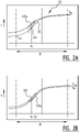
- a measured temperature profile 32 (T m ) ( Fig. 2A-B ) is compared with a reference temperature profile 34 (T ref ) over the length B and/or width C of the profile.
- T ref reference temperature profile
- the vertical axis corresponds to the central or boundary line 26 in a neutral position, i.e. without disturbances acting on air curtain 4.
- reference maximum temperature gradient 48 at location x 1 ( Fig. 2A ) along length B is compared with measured maximum temperature gradient 48a.
- location x 2 ( Fig. 2B ) of the measured maximum temperature gradient 50a is compared with the location x 1 of the reference maximum temperature gradient 50.
- the comparison(s) may lead to adjustments of the air curtain and/or air curtain device.
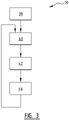
- the method 36 for operating device 2 starts with initiating step 38 for starting device 2, followed by activating step 40 to produce air curtain 4.
- a temperature profile 32 is measured to enable controller 44 to perform a comparing step 46 and define control actions to adjust air curtain 4.
- controller 44 may adjust air curtain 4 by manipulating the fan speed, heater and/or flow direction of outflow 8 to enhance the quality of air curtain 4.
- Air curtain device 2 can thus be applied to many locations. Examples hereof are for instance entrances to shops, loading and/or unloading positions, warehouses or logistical centers, and climate-controlled spaces.
Landscapes
- Engineering & Computer Science (AREA)
- Chemical & Material Sciences (AREA)
- Combustion & Propulsion (AREA)
- Mechanical Engineering (AREA)
- General Engineering & Computer Science (AREA)
- Physics & Mathematics (AREA)
- Fluid Mechanics (AREA)
- Curtains And Furnishings For Windows Or Doors (AREA)
- Air Conditioning Control Device (AREA)
Claims (14)
- Luftvorhangvorrichtung (2) zur Bereitstellung eines Luftvorhangs (4) in oder nahe einer Öffnung (20) in einer Wand (22), wobei die Vorrichtung Folgendes aufweist:- ein Gehäuse mit einer Luftverdrängungseinrichtung (10);- mindestens einen Lufteinlass (6) zum Zuführen von Luft in das Gehäuse;- mindestens eine Ausströmöffnung (8) zum Erzielen des Luftvorhangs;- einen Sensor (28); sowie- eine Steuerung (44) mit einer Verbindungseinrichtung, die zum Verbinden mit dem Sensor konfiguriert ist,dadurch gekennzeichnet, dass der Sensor zum Messen eines Temperaturprofils (32) konfiguriert ist, das sich über eine Länge (B) erstreckt, wobei die Länge durch den Luftvorhang in einer wesentlich horizontalen Richtung sowie im Wesentlichen senkrecht zu dem Luftvorhang verläuft, wodurch die Auswirkungen von äußeren Bedingungen und/oder Störungen auf den Luftvorhang gemessen werden, wobei der Sensor (28) Temperaturen in (Teil)-Abständen der Länge oder ein durchgehendes Temperaturprofil misst, und wobei die Steuerung zum Anpassen des Luftvorhangs auf der Basis von Unterschieden zwischen dem gemessenen Temperaturprofil (32) und dem Bezugstemperaturprofil (34) konfiguriert ist.
- Luftvorhangvorrichtung nach Anspruch 1, wobei der Sensor einen Infrarot-Sensor (28) aufweist.
- Luftvorhangvorrichtung nach Anspruch 1 oder 2, wobei die Steuerung eine Berechnungseinrichtung aufweist, die zur Bestimmung des größten Temperaturgradienten entlang der Länge des gemessenen Temperaturprofils konfiguriert ist.
- Luftvorhangvorrichtung nach Anspruch 1, 2 oder 3, weiterhin mit einer Anpassungseinrichtung zum Anpassen des Luftvorhangs auf der Basis der Unterschiede zwischen den gemessenen und den Bezugstemperaturprofilen.
- Luftvorhangvorrichtung nach einem oder mehreren der vorhergehenden Ansprüche, wobei die Länge (B) im Bereich von 1-20 m, vorzugsweise im Bereich von 2-10 m liegt.
- Luftvorhangvorrichtung nach einem oder mehreren der vorhergehenden Ansprüche, wobei das Temperaturprofil eine Breite (C) in einer Richtung im Wesentlichen parallel zu der Ebene der Öffnung in der Wand aufweist.
- Luftvorhangvorrichtung nach einem oder mehreren der vorhergehenden Ansprüche, weiterhin mit einem Detektor zur Erfassung von Personen, die sich dem Luftvorhang nähern.
- Luftvorhangvorrichtung nach einem oder mehreren der vorhergehenden Ansprüche, weiterhin mit einem Türpositionsdetektor, um zu ermöglichen, dass die Steuerung den Luftvorhang kompensiert.
- Luftvorhangvorrichtung nach einem oder mehreren der vorhergehenden Ansprüche, wobei der Sensor einteilig mit der Vorrichtung vorgesehen ist.
- Verfahren zur Erzeugung eines Luftvorhangs (4) in oder nahe einer Öffnung (20) in einer Wand (22), wobei das Verfahren folgende Schritte aufweist:- Bereitstellen einer Luftvorhangvorrichtung (2) nach einem oder mehreren der vorhergehenden Ansprüche;- Erzeugen des Luftvorhangs mit der Vorrichtung;- Messen des Temperaturprofils (32), das sich über eine Länge B erstreckt, welche durch den Luftvorhang in einer wesentlich horizontalen Richtung und im Wesentlichen senkrecht zu dem Luftvorhang verläuft, wobei der Sensor (28) Temperaturen in (Teil)-Abständen der Länge oder ein durchgehendes Temperaturprofil misst;- Vergleichen des gemessenen Temperaturprofils mit dem Bezugstemperaturprofil; sowie- Anpassen des Luftvorhangs auf der Basis des Vergleichens des gemessenen Temperaturprofils (32) mit dem Bezugstemperaturprofil (34) durch die Steuerung (44).
- Verfahren nach Anspruch 10, wobei der Luftvorhang auf der Basis eines Temperaturgradienten angepasst wird.
- Verfahren nach Anspruch 11, wobei der Temperaturgradient (48) den größten Temperaturgradienten entlang der Länge des gemessenen Temperaturprofils aufweist.
- Verfahren nach Anspruch 10, 11 oder 12, wobei der Luftvorhang auf der Basis einer Stelle angepasst wird, die den größten Temperaturgradienten aufweist.
- Verfahren nach einem oder mehreren der Ansprüche 10 bis 13, wobei die Steuerung den Luftvorhang anpasst, indem sie den Ausströmwinkel, die Lufttemperatur der Ausströmung und/oder die Geschwindigkeit der Ausströmung anpasst.
Applications Claiming Priority (2)
| Application Number | Priority Date | Filing Date | Title |
|---|---|---|---|
| NL2010998A NL2010998C2 (en) | 2013-06-18 | 2013-06-18 | Air curtain device measuring a temperature profile and method there for. |
| PCT/NL2014/050302 WO2014204297A1 (en) | 2013-06-18 | 2014-05-13 | Air curtain device measuring a temperature profile and method there for |
Publications (2)
| Publication Number | Publication Date |
|---|---|
| EP3011232A1 EP3011232A1 (de) | 2016-04-27 |
| EP3011232B1 true EP3011232B1 (de) | 2022-10-26 |
Family
ID=48951557
Family Applications (1)
| Application Number | Title | Priority Date | Filing Date |
|---|---|---|---|
| EP14727956.6A Active EP3011232B1 (de) | 2013-06-18 | 2014-05-13 | Luftvorhangvorrichtung zur messung eines temperaturprofils und verfahren dafür |
Country Status (5)
| Country | Link |
|---|---|
| US (1) | US20160146485A1 (de) |
| EP (1) | EP3011232B1 (de) |
| CA (1) | CA2915588A1 (de) |
| NL (1) | NL2010998C2 (de) |
| WO (1) | WO2014204297A1 (de) |
Families Citing this family (11)
| Publication number | Priority date | Publication date | Assignee | Title |
|---|---|---|---|---|
| US20170328601A1 (en) * | 2014-12-09 | 2017-11-16 | The Australian National University | Air curtain control system and method |
| FR3032391B1 (fr) * | 2015-02-06 | 2018-09-21 | Alstom Transport Technologies | Dispositif de generation de rideau d'air, notamment destine a equiper un vehicule ferroviaire |
| US10648683B2 (en) * | 2016-07-19 | 2020-05-12 | Mars Air Systems, LLC | Intelligent climate management system control systems and methods |
| WO2018028993A1 (en) | 2016-08-08 | 2018-02-15 | Arcelik Anonim Sirketi | Portable air-conditioning device |
| CN106568172B (zh) * | 2016-11-08 | 2019-06-14 | 胡佳 | 节能温度控制方法、装置及空调遥控系统 |
| CN108116210A (zh) * | 2016-11-28 | 2018-06-05 | 郑州宇通客车股份有限公司 | 风幕门及使用该风幕门的车辆 |
| CZ307950B6 (cs) * | 2018-07-19 | 2019-09-04 | Stavoklima S.R.O. | Způsob regulace tepelného a vzduchového výkonu vzduchové dveřní clony |
| JP7585795B2 (ja) * | 2021-01-08 | 2024-11-19 | トヨタ自動車株式会社 | 空調システム |
| KR102303758B1 (ko) * | 2021-05-21 | 2021-09-16 | 김유곤 | 드라이룸의 국부 제습을 위한 다단 제습 시스템 |
| US11788747B2 (en) | 2021-11-10 | 2023-10-17 | Aeolus Air Devices LLC | Airfield systems, devices, and methods |
| CN116221936B (zh) * | 2023-03-07 | 2023-09-05 | 北京科技大学 | 一种适应变化热需求的分区多模式送风方法 |
Family Cites Families (7)
| Publication number | Priority date | Publication date | Assignee | Title |
|---|---|---|---|---|
| DE4420167C1 (de) * | 1994-06-09 | 1995-11-09 | Teddington Controls Gmbh | Kompakt-Luftschleieranlage |
| DE19542714A1 (de) * | 1995-11-16 | 1997-05-22 | Ttl Tuer & Torluftschleier Luf | Verfahren und Vorrichtung zur Verminderung einer Luftströmung durch eine offene Tür oder ein offenes Tor |
| US5791152A (en) * | 1997-06-06 | 1998-08-11 | Daewoo Electronics Co., Ltd. | Refrigerator having a device for generating an air curtain and method for controlling an air curtain generating operation |
| DE19932153C1 (de) * | 1999-07-12 | 2000-11-23 | Dorma Gmbh & Co Kg | Schiebetür |
| JP4165604B2 (ja) * | 2006-07-31 | 2008-10-15 | ダイキン工業株式会社 | 空調制御装置および空調制御方法 |
| CA2567863C (en) * | 2006-11-14 | 2014-04-22 | Berner International Corporation | Programmable controller for condition air curtains |
| JP5111445B2 (ja) * | 2008-09-10 | 2013-01-09 | 三菱電機株式会社 | 空気調和機 |
-
2013
- 2013-06-18 NL NL2010998A patent/NL2010998C2/en not_active IP Right Cessation
-
2014
- 2014-05-13 CA CA2915588A patent/CA2915588A1/en not_active Abandoned
- 2014-05-13 WO PCT/NL2014/050302 patent/WO2014204297A1/en not_active Ceased
- 2014-05-13 EP EP14727956.6A patent/EP3011232B1/de active Active
- 2014-05-13 US US14/899,249 patent/US20160146485A1/en not_active Abandoned
Also Published As
| Publication number | Publication date |
|---|---|
| EP3011232A1 (de) | 2016-04-27 |
| CA2915588A1 (en) | 2014-12-24 |
| WO2014204297A1 (en) | 2014-12-24 |
| US20160146485A1 (en) | 2016-05-26 |
| NL2010998C2 (en) | 2014-12-22 |
Similar Documents
| Publication | Publication Date | Title |
|---|---|---|
| US20160146485A1 (en) | Air curtain device measuring a temperature profile and method there for | |
| CA2826476C (en) | A ventilation system for a passenger transit vehicle | |
| EP2863137B1 (de) | Systeme und Verfahren zur Belüftung eines Gebäudes | |
| US20130008224A1 (en) | Method for calibration of a co2 concentration sensor and a measuring device | |
| KR102282451B1 (ko) | 시스템 루버의 동작을 제어하는 장치 | |
| CN106196408B (zh) | 空调器的参数的控制方法、参数控制装置和空调器 | |
| CN110645645B (zh) | 一种地下车库防结露除湿装置的控制方法 | |
| US20210172779A1 (en) | Systems and methods for control of an air duct | |
| KR100452350B1 (ko) | 천장형 공기조화기 및 그 제어방법 | |
| WO2010122117A1 (en) | Ventilation system involving ultrasonic flow measurement | |
| CN105465955A (zh) | 一种天气联动空调控制方法 | |
| KR20130114769A (ko) | 차량의 배기가스 유입 방지 방법 및 시스템 | |
| JP2021073894A (ja) | 農業用ハウスの換気窓制御システム及び換気窓制御方法 | |
| EP2314944A2 (de) | Überdruckbasiertes System zum Schutz vertikaler Evakuierungswege vor Rauchinfiltration | |
| EP3396263B1 (de) | Multisensoreinheit, anordnung und verfahren zur verwaltung der raumklimabedingungen eines raumes oder einer zone | |
| JP2016089588A (ja) | ブラインド制御装置、ブラインド制御システム、及びブラインド制御方法 | |
| KR20180118834A (ko) | 통풍경로를 제어하는 환기시스템 및 환기방법 | |
| KR101821625B1 (ko) | 루버 시스템 | |
| KR20160015856A (ko) | 차단 성능이 극대화된 토출각도 자동 조절형 에어커튼 시스템 | |
| KR101774814B1 (ko) | 차량용 공조장치 | |
| JP2019027746A (ja) | 店舗向け給気量制御システム | |
| US20170130983A1 (en) | Outside air distribution system | |
| EP3598011B1 (de) | Verfahren zur steuerung der thermischen und pneumatischen leistung eines luftvorhangs | |
| KR102045419B1 (ko) | 차량용 창유리 디포깅 장치 | |
| CN108444071B (zh) | 一种传感器位置控制方法、装置及空调 |
Legal Events
| Date | Code | Title | Description |
|---|---|---|---|
| PUAI | Public reference made under article 153(3) epc to a published international application that has entered the european phase |
Free format text: ORIGINAL CODE: 0009012 |
|
| 17P | Request for examination filed |
Effective date: 20151218 |
|
| AK | Designated contracting states |
Kind code of ref document: A1 Designated state(s): AL AT BE BG CH CY CZ DE DK EE ES FI FR GB GR HR HU IE IS IT LI LT LU LV MC MK MT NL NO PL PT RO RS SE SI SK SM TR |
|
| AX | Request for extension of the european patent |
Extension state: BA ME |
|
| DAX | Request for extension of the european patent (deleted) | ||
| STAA | Information on the status of an ep patent application or granted ep patent |
Free format text: STATUS: EXAMINATION IS IN PROGRESS |
|
| 17Q | First examination report despatched |
Effective date: 20190306 |
|
| REG | Reference to a national code |
Ref country code: DE Ref legal event code: R079 Ref document number: 602014085322 Country of ref document: DE Free format text: PREVIOUS MAIN CLASS: F24F0011000000 Ipc: F24F0009000000 |
|
| GRAP | Despatch of communication of intention to grant a patent |
Free format text: ORIGINAL CODE: EPIDOSNIGR1 |
|
| STAA | Information on the status of an ep patent application or granted ep patent |
Free format text: STATUS: GRANT OF PATENT IS INTENDED |
|
| RIC1 | Information provided on ipc code assigned before grant |
Ipc: F24F 120/10 20180101ALI20220520BHEP Ipc: F24F 110/10 20180101ALI20220520BHEP Ipc: F24F 11/30 20180101ALI20220520BHEP Ipc: F24F 9/00 20060101AFI20220520BHEP |
|
| INTG | Intention to grant announced |
Effective date: 20220617 |
|
| GRAS | Grant fee paid |
Free format text: ORIGINAL CODE: EPIDOSNIGR3 |
|
| GRAA | (expected) grant |
Free format text: ORIGINAL CODE: 0009210 |
|
| STAA | Information on the status of an ep patent application or granted ep patent |
Free format text: STATUS: THE PATENT HAS BEEN GRANTED |
|
| AK | Designated contracting states |
Kind code of ref document: B1 Designated state(s): AL AT BE BG CH CY CZ DE DK EE ES FI FR GB GR HR HU IE IS IT LI LT LU LV MC MK MT NL NO PL PT RO RS SE SI SK SM TR |
|
| REG | Reference to a national code |
Ref country code: GB Ref legal event code: FG4D |
|
| REG | Reference to a national code |
Ref country code: CH Ref legal event code: EP |
|
| REG | Reference to a national code |
Ref country code: AT Ref legal event code: REF Ref document number: 1527285 Country of ref document: AT Kind code of ref document: T Effective date: 20221115 |
|
| REG | Reference to a national code |
Ref country code: DE Ref legal event code: R096 Ref document number: 602014085322 Country of ref document: DE |
|
| REG | Reference to a national code |
Ref country code: IE Ref legal event code: FG4D |
|
| REG | Reference to a national code |
Ref country code: NL Ref legal event code: FP |
|
| REG | Reference to a national code |
Ref country code: LT Ref legal event code: MG9D |
|
| REG | Reference to a national code |
Ref country code: AT Ref legal event code: MK05 Ref document number: 1527285 Country of ref document: AT Kind code of ref document: T Effective date: 20221026 |
|
| PG25 | Lapsed in a contracting state [announced via postgrant information from national office to epo] |
Ref country code: SE Free format text: LAPSE BECAUSE OF FAILURE TO SUBMIT A TRANSLATION OF THE DESCRIPTION OR TO PAY THE FEE WITHIN THE PRESCRIBED TIME-LIMIT Effective date: 20221026 Ref country code: PT Free format text: LAPSE BECAUSE OF FAILURE TO SUBMIT A TRANSLATION OF THE DESCRIPTION OR TO PAY THE FEE WITHIN THE PRESCRIBED TIME-LIMIT Effective date: 20230227 Ref country code: NO Free format text: LAPSE BECAUSE OF FAILURE TO SUBMIT A TRANSLATION OF THE DESCRIPTION OR TO PAY THE FEE WITHIN THE PRESCRIBED TIME-LIMIT Effective date: 20230126 Ref country code: LT Free format text: LAPSE BECAUSE OF FAILURE TO SUBMIT A TRANSLATION OF THE DESCRIPTION OR TO PAY THE FEE WITHIN THE PRESCRIBED TIME-LIMIT Effective date: 20221026 Ref country code: FI Free format text: LAPSE BECAUSE OF FAILURE TO SUBMIT A TRANSLATION OF THE DESCRIPTION OR TO PAY THE FEE WITHIN THE PRESCRIBED TIME-LIMIT Effective date: 20221026 Ref country code: ES Free format text: LAPSE BECAUSE OF FAILURE TO SUBMIT A TRANSLATION OF THE DESCRIPTION OR TO PAY THE FEE WITHIN THE PRESCRIBED TIME-LIMIT Effective date: 20221026 Ref country code: AT Free format text: LAPSE BECAUSE OF FAILURE TO SUBMIT A TRANSLATION OF THE DESCRIPTION OR TO PAY THE FEE WITHIN THE PRESCRIBED TIME-LIMIT Effective date: 20221026 |
|
| PG25 | Lapsed in a contracting state [announced via postgrant information from national office to epo] |
Ref country code: RS Free format text: LAPSE BECAUSE OF FAILURE TO SUBMIT A TRANSLATION OF THE DESCRIPTION OR TO PAY THE FEE WITHIN THE PRESCRIBED TIME-LIMIT Effective date: 20221026 Ref country code: PL Free format text: LAPSE BECAUSE OF FAILURE TO SUBMIT A TRANSLATION OF THE DESCRIPTION OR TO PAY THE FEE WITHIN THE PRESCRIBED TIME-LIMIT Effective date: 20221026 Ref country code: LV Free format text: LAPSE BECAUSE OF FAILURE TO SUBMIT A TRANSLATION OF THE DESCRIPTION OR TO PAY THE FEE WITHIN THE PRESCRIBED TIME-LIMIT Effective date: 20221026 Ref country code: IS Free format text: LAPSE BECAUSE OF FAILURE TO SUBMIT A TRANSLATION OF THE DESCRIPTION OR TO PAY THE FEE WITHIN THE PRESCRIBED TIME-LIMIT Effective date: 20230226 Ref country code: HR Free format text: LAPSE BECAUSE OF FAILURE TO SUBMIT A TRANSLATION OF THE DESCRIPTION OR TO PAY THE FEE WITHIN THE PRESCRIBED TIME-LIMIT Effective date: 20221026 Ref country code: GR Free format text: LAPSE BECAUSE OF FAILURE TO SUBMIT A TRANSLATION OF THE DESCRIPTION OR TO PAY THE FEE WITHIN THE PRESCRIBED TIME-LIMIT Effective date: 20230127 |
|
| P01 | Opt-out of the competence of the unified patent court (upc) registered |
Effective date: 20230507 |
|
| REG | Reference to a national code |
Ref country code: DE Ref legal event code: R097 Ref document number: 602014085322 Country of ref document: DE |
|
| PG25 | Lapsed in a contracting state [announced via postgrant information from national office to epo] |
Ref country code: SM Free format text: LAPSE BECAUSE OF FAILURE TO SUBMIT A TRANSLATION OF THE DESCRIPTION OR TO PAY THE FEE WITHIN THE PRESCRIBED TIME-LIMIT Effective date: 20221026 Ref country code: RO Free format text: LAPSE BECAUSE OF FAILURE TO SUBMIT A TRANSLATION OF THE DESCRIPTION OR TO PAY THE FEE WITHIN THE PRESCRIBED TIME-LIMIT Effective date: 20221026 Ref country code: EE Free format text: LAPSE BECAUSE OF FAILURE TO SUBMIT A TRANSLATION OF THE DESCRIPTION OR TO PAY THE FEE WITHIN THE PRESCRIBED TIME-LIMIT Effective date: 20221026 Ref country code: DK Free format text: LAPSE BECAUSE OF FAILURE TO SUBMIT A TRANSLATION OF THE DESCRIPTION OR TO PAY THE FEE WITHIN THE PRESCRIBED TIME-LIMIT Effective date: 20221026 Ref country code: CZ Free format text: LAPSE BECAUSE OF FAILURE TO SUBMIT A TRANSLATION OF THE DESCRIPTION OR TO PAY THE FEE WITHIN THE PRESCRIBED TIME-LIMIT Effective date: 20221026 |
|
| PG25 | Lapsed in a contracting state [announced via postgrant information from national office to epo] |
Ref country code: SK Free format text: LAPSE BECAUSE OF FAILURE TO SUBMIT A TRANSLATION OF THE DESCRIPTION OR TO PAY THE FEE WITHIN THE PRESCRIBED TIME-LIMIT Effective date: 20221026 Ref country code: AL Free format text: LAPSE BECAUSE OF FAILURE TO SUBMIT A TRANSLATION OF THE DESCRIPTION OR TO PAY THE FEE WITHIN THE PRESCRIBED TIME-LIMIT Effective date: 20221026 |
|
| PLBE | No opposition filed within time limit |
Free format text: ORIGINAL CODE: 0009261 |
|
| STAA | Information on the status of an ep patent application or granted ep patent |
Free format text: STATUS: NO OPPOSITION FILED WITHIN TIME LIMIT |
|
| 26N | No opposition filed |
Effective date: 20230727 |
|
| PG25 | Lapsed in a contracting state [announced via postgrant information from national office to epo] |
Ref country code: SI Free format text: LAPSE BECAUSE OF FAILURE TO SUBMIT A TRANSLATION OF THE DESCRIPTION OR TO PAY THE FEE WITHIN THE PRESCRIBED TIME-LIMIT Effective date: 20221026 |
|
| REG | Reference to a national code |
Ref country code: CH Ref legal event code: PL |
|
| PG25 | Lapsed in a contracting state [announced via postgrant information from national office to epo] |
Ref country code: MC Free format text: LAPSE BECAUSE OF FAILURE TO SUBMIT A TRANSLATION OF THE DESCRIPTION OR TO PAY THE FEE WITHIN THE PRESCRIBED TIME-LIMIT Effective date: 20221026 |
|
| PG25 | Lapsed in a contracting state [announced via postgrant information from national office to epo] |
Ref country code: MC Free format text: LAPSE BECAUSE OF FAILURE TO SUBMIT A TRANSLATION OF THE DESCRIPTION OR TO PAY THE FEE WITHIN THE PRESCRIBED TIME-LIMIT Effective date: 20221026 Ref country code: LU Free format text: LAPSE BECAUSE OF NON-PAYMENT OF DUE FEES Effective date: 20230513 Ref country code: LI Free format text: LAPSE BECAUSE OF NON-PAYMENT OF DUE FEES Effective date: 20230531 Ref country code: CH Free format text: LAPSE BECAUSE OF NON-PAYMENT OF DUE FEES Effective date: 20230531 |
|
| REG | Reference to a national code |
Ref country code: IE Ref legal event code: MM4A |
|
| PG25 | Lapsed in a contracting state [announced via postgrant information from national office to epo] |
Ref country code: IE Free format text: LAPSE BECAUSE OF NON-PAYMENT OF DUE FEES Effective date: 20230513 |
|
| PG25 | Lapsed in a contracting state [announced via postgrant information from national office to epo] |
Ref country code: IE Free format text: LAPSE BECAUSE OF NON-PAYMENT OF DUE FEES Effective date: 20230513 |
|
| PG25 | Lapsed in a contracting state [announced via postgrant information from national office to epo] |
Ref country code: IT Free format text: LAPSE BECAUSE OF FAILURE TO SUBMIT A TRANSLATION OF THE DESCRIPTION OR TO PAY THE FEE WITHIN THE PRESCRIBED TIME-LIMIT Effective date: 20221026 |
|
| PG25 | Lapsed in a contracting state [announced via postgrant information from national office to epo] |
Ref country code: BG Free format text: LAPSE BECAUSE OF FAILURE TO SUBMIT A TRANSLATION OF THE DESCRIPTION OR TO PAY THE FEE WITHIN THE PRESCRIBED TIME-LIMIT Effective date: 20221026 |
|
| PG25 | Lapsed in a contracting state [announced via postgrant information from national office to epo] |
Ref country code: BG Free format text: LAPSE BECAUSE OF FAILURE TO SUBMIT A TRANSLATION OF THE DESCRIPTION OR TO PAY THE FEE WITHIN THE PRESCRIBED TIME-LIMIT Effective date: 20221026 |
|
| PG25 | Lapsed in a contracting state [announced via postgrant information from national office to epo] |
Ref country code: CY Free format text: LAPSE BECAUSE OF FAILURE TO SUBMIT A TRANSLATION OF THE DESCRIPTION OR TO PAY THE FEE WITHIN THE PRESCRIBED TIME-LIMIT; INVALID AB INITIO Effective date: 20140513 |
|
| PG25 | Lapsed in a contracting state [announced via postgrant information from national office to epo] |
Ref country code: HU Free format text: LAPSE BECAUSE OF FAILURE TO SUBMIT A TRANSLATION OF THE DESCRIPTION OR TO PAY THE FEE WITHIN THE PRESCRIBED TIME-LIMIT; INVALID AB INITIO Effective date: 20140513 |
|
| PG25 | Lapsed in a contracting state [announced via postgrant information from national office to epo] |
Ref country code: TR Free format text: LAPSE BECAUSE OF FAILURE TO SUBMIT A TRANSLATION OF THE DESCRIPTION OR TO PAY THE FEE WITHIN THE PRESCRIBED TIME-LIMIT Effective date: 20221026 |
|
| PGFP | Annual fee paid to national office [announced via postgrant information from national office to epo] |
Ref country code: NL Payment date: 20260526 Year of fee payment: 13 |
|
| PGFP | Annual fee paid to national office [announced via postgrant information from national office to epo] |
Ref country code: GB Payment date: 20260527 Year of fee payment: 13 |
|
| PGFP | Annual fee paid to national office [announced via postgrant information from national office to epo] |
Ref country code: DE Payment date: 20260528 Year of fee payment: 13 |
|
| PGFP | Annual fee paid to national office [announced via postgrant information from national office to epo] |
Ref country code: BE Payment date: 20260527 Year of fee payment: 13 |
|
| PGFP | Annual fee paid to national office [announced via postgrant information from national office to epo] |
Ref country code: FR Payment date: 20260525 Year of fee payment: 13 |