EP3011495B1 - Erfassung multimodaler bilder zur irisabbildung - Google Patents
Erfassung multimodaler bilder zur irisabbildung Download PDFInfo
- Publication number
- EP3011495B1 EP3011495B1 EP14814311.8A EP14814311A EP3011495B1 EP 3011495 B1 EP3011495 B1 EP 3011495B1 EP 14814311 A EP14814311 A EP 14814311A EP 3011495 B1 EP3011495 B1 EP 3011495B1
- Authority
- EP
- European Patent Office
- Prior art keywords
- image capture
- image
- optical assembly
- capture region
- view
- Prior art date
- Legal status (The legal status is an assumption and is not a legal conclusion. Google has not performed a legal analysis and makes no representation as to the accuracy of the status listed.)
- Not-in-force
Links
Images




Classifications
-
- G—PHYSICS
- G02—OPTICS
- G02B—OPTICAL ELEMENTS, SYSTEMS OR APPARATUS
- G02B13/00—Optical objectives specially designed for the purposes specified below
- G02B13/001—Miniaturised objectives for electronic devices, e.g. portable telephones, webcams, PDAs, small digital cameras
- G02B13/0015—Miniaturised objectives for electronic devices, e.g. portable telephones, webcams, PDAs, small digital cameras characterised by the lens design
-
- A—HUMAN NECESSITIES
- A61—MEDICAL OR VETERINARY SCIENCE; HYGIENE
- A61B—DIAGNOSIS; SURGERY; IDENTIFICATION
- A61B3/00—Apparatus for testing the eyes; Instruments for examining the eyes
- A61B3/10—Objective types, i.e. instruments for examining the eyes independent of the patients' perceptions or reactions
- A61B3/12—Objective types, i.e. instruments for examining the eyes independent of the patients' perceptions or reactions for looking at the eye fundus, e.g. ophthalmoscopes
- A61B3/1216—Objective types, i.e. instruments for examining the eyes independent of the patients' perceptions or reactions for looking at the eye fundus, e.g. ophthalmoscopes for diagnostics of the iris
-
- A—HUMAN NECESSITIES
- A61—MEDICAL OR VETERINARY SCIENCE; HYGIENE
- A61B—DIAGNOSIS; SURGERY; IDENTIFICATION
- A61B5/00—Measuring for diagnostic purposes; Identification of persons
- A61B5/117—Identification of persons
- A61B5/1171—Identification of persons based on the shapes or appearances of their bodies or parts thereof
-
- G—PHYSICS
- G02—OPTICS
- G02B—OPTICAL ELEMENTS, SYSTEMS OR APPARATUS
- G02B5/00—Optical elements other than lenses
- G02B5/20—Filters
- G02B5/208—Filters for use with infrared or ultraviolet radiation, e.g. for separating visible light from infrared and/or ultraviolet radiation
-
- G—PHYSICS
- G06—COMPUTING OR CALCULATING; COUNTING
- G06V—IMAGE OR VIDEO RECOGNITION OR UNDERSTANDING
- G06V40/00—Recognition of biometric, human-related or animal-related patterns in image or video data
- G06V40/10—Human or animal bodies, e.g. vehicle occupants or pedestrians; Body parts, e.g. hands
- G06V40/18—Eye characteristics, e.g. of the iris
- G06V40/19—Sensors therefor
-
- G—PHYSICS
- G06—COMPUTING OR CALCULATING; COUNTING
- G06V—IMAGE OR VIDEO RECOGNITION OR UNDERSTANDING
- G06V40/00—Recognition of biometric, human-related or animal-related patterns in image or video data
- G06V40/10—Human or animal bodies, e.g. vehicle occupants or pedestrians; Body parts, e.g. hands
- G06V40/18—Eye characteristics, e.g. of the iris
- G06V40/197—Matching; Classification
-
- H—ELECTRICITY
- H04—ELECTRIC COMMUNICATION TECHNIQUE
- H04N—PICTORIAL COMMUNICATION, e.g. TELEVISION
- H04N23/00—Cameras or camera modules comprising electronic image sensors; Control thereof
- H04N23/50—Constructional details
- H04N23/55—Optical parts specially adapted for electronic image sensors; Mounting thereof
-
- H—ELECTRICITY
- H04—ELECTRIC COMMUNICATION TECHNIQUE
- H04N—PICTORIAL COMMUNICATION, e.g. TELEVISION
- H04N23/00—Cameras or camera modules comprising electronic image sensors; Control thereof
- H04N23/60—Control of cameras or camera modules
- H04N23/667—Camera operation mode switching, e.g. between still and video, sport and normal or high- and low-resolution modes
-
- A—HUMAN NECESSITIES
- A61—MEDICAL OR VETERINARY SCIENCE; HYGIENE
- A61B—DIAGNOSIS; SURGERY; IDENTIFICATION
- A61B5/00—Measuring for diagnostic purposes; Identification of persons
- A61B5/117—Identification of persons
Definitions
- the invention relates to an imaging apparatus and method, which imaging apparatus and method enables obtaining images of one or more features of a subject's eye for biometric identification.
- the invention is particularly operable to obtain images in a first mode and in a second mode, wherein at least the first image acquisition mode is optimized for iris image capture for the purposes of iris recognition.
- Methods for biometric identification based on facial features, including features of the eye are known.
- Methods for iris recognition implement pattern-recognition techniques to compare an acquired image of a subject's iris against a previously acquired image of the subject's iris, and thereby determine or verify identity of the subject.
- a digital template corresponding to an acquired iris image is encoded based on the image, using mathematical / statistical algorithms.
- the digital template is compared against databases of previously encoded digital templates (corresponding to previously acquired iris images), for locating a match and thereby determining or verifying identity of the subject.
- Apparatuses for iris recognition may comprise an imaging apparatus for capturing an image of the subject's iris(es) and an image processing apparatus for comparing the captured image against previously stored iris image information.
- the imaging apparatus and image processing apparatus may comprise separate devices, or may be combined within a single device.
- iris recognition apparatuses have been previously available as dedicated or stand alone devices, it is increasingly desirable to incorporate iris recognition capabilities into mobile communication devices or mobile computing devices (collectively referred to as "mobile devices") having inbuilt cameras, such as for example, mobile phones, smart phones, personal digital assistants, tablets or laptop devices.
- mobile devices mobile communication devices or mobile computing devices having inbuilt cameras, such as for example, mobile phones, smart phones, personal digital assistants, tablets or laptop devices.
- iris imaging particularly necessitates positioning of a subject's iris within a defined image capture region, such that the iris image acquired by the imaging apparatus satisfies a minimum pixel resolution in the object plane.
- Configuring a camera inbuilt into a mobile device in this manner may render the camera unsuitable for multiple uses (such as for iris imaging as well as video conferencing, video recording or photography purposes) while maintaining image sharpness and detail.
- Prior art solutions for altering an object plane of a camera typically involve a zoom lens type arrangement, where the lens assembly comprises a number of individual lenses that may slide axially along the body of the lens assembly to change focal length and magnification of the lens assembly.
- zoom lenses are expensive and bulky, both of which provide serious disincentives for use in cameras inbuilt into mobile devices.
- IR image capture typically relies on infrared (IR) wavelengths
- non-iris image capture usually seeks to eliminate IR wavelengths by using IR cut filters (filters which reflect or absorb IR wavelengths, while allowing visible wavelengths to pass through the lens assembly and on to the image sensor).
- IR cut filters filters which reflect or absorb IR wavelengths, while allowing visible wavelengths to pass through the lens assembly and on to the image sensor.
- WO98/08439 describes an apparatus for the iris acquiring images. At least one wide field of view camera and with an associated illuminator obtains sufficient images of a person to be identified so that x, y, z coordinates can be established for the expected position of that person's eye.
- US2013/0051631 is directed towards methods and systems for capturing artifact-free biometric images of an eye.
- the eye may be in motion and in the presence of partially-reflective eyewear.
- the method may include acquiring, by a first sensor, a first image of an eye while the eye is illuminated by a first illuminator.
- the first image may include a region of interest.
- the first sensor may be disposed at a fixed displacement from the first illuminator and a second sensor.
- the second sensor may acquire, within a predetermined period of time from the acquisition of the first image, a second image of the eye.
- the second image may include the region of interest.
- An image processor may determine if at least one of the first and second images include artifacts arising from one or both of the first illuminator and eyewear, within the region of interest.
- a system for multimodal biometric identification has a first imaging system that detects one or more subjects in a first field of view, including a targeted subject having a first biometric characteristic and a second biometric characteristic; a second imaging system that captures a first image of the first biometric characteristic according to first photons, where the first biometric characteristic is positioned in a second field of view smaller than the first field of view, and the first image includes first data for biometric identification; a third imaging system that captures a second image of the second biometric characteristic according to second photons, where the second biometric characteristic is positioned in a third field of view which is smaller than the first and second fields of view, and the second image includes second data for biometric identification.
- At least one active illumination source emits the second photons.
- the invention comprises an imaging apparatus housed at least partially within a mobile device housing, and configured to enable multiple image acquisition modes.
- the imaging apparatus includes an image sensor comprising an imaging surface, a first optical assembly, a second optical assembly and a controller.
- the first optical assembly of the invention may be positioned over a first image capture region of the imaging surface, and may define a first field of view - such that the first optical assembly images onto the first image capture region, any object plane within the first field of view.
- the second optical assembly may be positioned over a second image capture region of the imaging surface, and may define a second field of view - such that the second optical assembly images onto the second image capture region, any object plane within the second field of view.
- the first optical assembly and second optical assembly of the imaging apparatus may be integrally formed.
- imaging surfaces respectively underlying the first image capture region and the second image capture region may be discretely formed.
- Each of the first optical assembly and the second optical assembly comprise at least one of a lens or an optical filter.
- the first optical assembly may be interpositioned between the first image capture region and a third optical assembly that is non-substitutably interposed between the image sensor and the first and second fields of view.
- the second optical assembly may be interpositioned between the second image capture region and the third optical assembly.
- the first optical assembly may be configured to confer upon the imaging apparatus, a first set of image capture properties corresponding to the first field of view.
- the first set of image capture properties may differ from a second set of image capture properties conferred upon the imaging apparatus by the second optical assembly corresponding to the second field of view.
- the first set of image capture properties may differ from the second set of image capture properties on the basis of one or more of field of view, focus, focal length, depth of field, optical filtering properties, magnification, modulation transfer function (MTF), position of a principal plane of an optical assembly, or position of a focal plane of an optical assembly.
- MTF modulation transfer function
- the first optical assembly or the second optical assembly of the imaging apparatus may comprise one or more of an infra-red pass filter, a narrow band filter, an infra-red cut filter, a refractive optical element, or a plano-parallel refractive element.
- the controller within the imaging apparatus may be configured to process image data from pixels within the first image capture region responsive to triggering of a first image capture mode, and to process image data from pixels within the second image capture region responsive to triggering of a second image capture mode.
- the controller may be located at least partially outside the mobile device housing.
- the controller may be configured to selectively process image data from within the first image capture region or the second image capture region during any one of image capture, image parsing or image rendering.
- the controller may be configured to respond to triggering of the first image capture mode by processing a first set of image data acquired from pixels within the first image capture region, and a second set of image data acquired from pixels within the second image capture region.
- An image based on one of the first set of image data and the second set of image data from pixels may be rendered by the controller for display. Thereafter the other of the first set of image data and the second set of image data may be used for comparing iris information within such first or second set of image data with stored iris information corresponding to at least one iris, and for rendering a match decision or a non-match decision based on an output of the comparison.
- the image thus rendered for display to an operator enables the operator to optimize image capture parameters for iris imaging.
- the first image capture mode or the second image capture mode may be respectively triggered responsive to an object of interest being positioned within the first field of view or the second field of view. At least one of the first image capture mode and second image capture mode may be optimized for iris imaging.
- the first image capture region and the second image capture region may be separated by a transition region, wherein pixel data from within the transition region is disregarding during image capture, image parsing or image rendering.
- the imaging apparatus may comprise a camera disposed within a housing of any one of a mobile telecommunication device.
- the invention may comprise a method for enabling multiple image acquisition modes in an imaging apparatus, wherein the imaging apparatus is housed at least partially within a mobile device housing.
- the method may comprise (i) defining for an image sensor comprising an imaging surface, a first image capture region and a second image capture region within the imaging surface (ii) positioning a first optical assembly over the first image capture region, wherein the first optical assembly defines a first field of view and images onto the first image capture region, any object plane within the first field of view (iii) positioning a second optical assembly over the second image capture region, wherein the second optical assembly defines a second field of view and images onto the second image capture region, any object plane within the second field of view and (iv) configuring a controller to (a) process image data from pixels within the first image capture region responsive to triggering of a first image capture mode, and (b) process image data from pixels within the second image capture region responsive to triggering of a second image capture mode.
- the method embodiments of the invention may include some or all of the limitations discussed above in connection with the apparatus embodiment.
- Figure 1 is a functional block diagram of a mobile device 100 configured for iris image based recognition, comprising an imaging apparatus 102 and an image processing apparatus 104.
- Imaging apparatus 102 acquires an image of the subject's iris and transmits the image to image processing apparatus 104.
- the image captured by imaging apparatus 102 may be a still image or a video image.
- Image processing apparatus 104 thereafter analyses the acquired image frame(s) and compares the corresponding digital feature set with digital templates encoded and stored based on previously acquired iris images, to identify the subject, or to verify the identity of the subject.
- mobile device 100 may include other components, including for extracting still frames from video images, for processing and digitizing image data, for enrolment of iris images (the process of capturing, and storing iris information for a subject, and associating the stored information with that subject) and comparison (the process of comparing iris information acquired from a subject against information previously acquired during enrolment, for identification or verification of the subject's identity), and for enabling communication between components of the mobile device.
- the imaging apparatus, image processing apparatus and other components of the mobile device may each comprise separate devices, or may be combined within a single mobile device.
- Figure 2 illustrates an exemplary embodiment of imaging apparatus 102 having housing 202, image sensor 204 and an optical assembly 206, wherein image sensor 204 and optical assembly 206 are disposed within the housing 206.
- Imaging apparatus 102 may comprise a conventional solid state still camera or video camera, and image sensor 204 may comprise a charged coupled device (CCD) or a complementary metal oxide semiconductor (CMOS) device. Image sensor 204 may be selected for sensitivity at least to light having wavelengths anywhere in the range of 400 nanometres to 1000 nanometres.
- Optical assembly 206 may comprise an integrally formed or single unitarily formed element, or may comprise an assembly of optical elements selected and configured for achieving desired image forming properties.
- the imaging apparatus as illustrated has a fixed focus, of a type that is conventionally disposed within mobile devices.
- optical assembly 206 and image sensor 204 may be configured and disposed relative to each other, such that when a subject's eye E is positioned at object plane OP1, an in-focus image E' of the eye is formed at image plane IP1, which image plane coincides with an imaging surface of image sensor 204.
- an object O when an object O is positioned at object plane OP2 (which object plane OP2 is located further away from the imaging apparatus in comparison to object plane OP1), an image O' of the object is formed at image plane IP2, which image plane does not coincide with the imaging surface of image sensor 204 - and thereby causes an out-of-focus image to acquired by image sensor 204.
- the present invention seeks to provide a solution to the above problems by providing an imaging apparatus capable of alternating between two or more image capture configurations or modes, without recourse to moving parts.
- Figures 3 and 4 illustrate exemplary embodiments of the invention.
- Figure 3 illustrates a dual mode camera configuration, wherein image sensor 301 comprises a first image capture region 302 and a second image capture region 303. Positioned between image sensor 301 and intended object positions are first optical assembly 304 and second optical assembly 305. As illustrated, first optical assembly 304 is interposed in front of first image capture region 302 of image sensor 301, and second optical assembly 305 is interposed in front of second image capture region 303 of image sensor 301.
- the first optical assembly 304 and second optical assembly 305 may be selected such that they each have different working distance and / or have different magnification and / or have different optical filtering properties.
- the first optical assembly 304 may configured and selected to have a first field of view 306 and a first object plane 306', while the second optical assembly 305 may be configured and selected to have a second field of view 307 and optionally a second object plane 307' and depth of field.
- the first and second optical assemblies are positioned relative to the image sensor such that the image of an object positioned within the first field of view 306 and at the first object plane 306' will be projected on to the first image capture region 302 of image sensor 301, while images of objects positioned within the second field of view 307 will be projected on to the second image capture region 303 of image sensor 301.
- first optical assembly 304 may be configured such that object plane 306' is selected to be appropriate for iris image capture, while second optical assembly 305 may be configured to satisfy constraints optimal for non-iris image capture (such as for example for general purpose photography).
- the invention can selectively record information depending on whether the camera is in a first image capture mode or in a second image capture mode.
- image data from pixels within first image capture region 302 is parsed and used while image data from second image capture region 303 is ignored.
- image data from pixels in second image capture region 303 is parsed and used while image date from first image capture region 302 is ignored.
- a first set of image data comprising image data from pixels within first image capture region 302 is processed along a second set of image data comprising image data from pixels within second image capture region 303.
- An image based on one of the first set of image data and the second set of image data is rendered for display to an operator of the imaging apparatus, while the other of said first or second set of image data may be utilized for comparing iris information within said image data set with stored iris information corresponding to at least one iris, and thereafter rendering a match or non-match decision based on output of such comparison.
- the image rendered for display enables the operator to optimize image capture parameters (such as for example, position of the subject's eye, illumination, orientation of the imaging apparatus or mobile device) for iris imaging.
- the first image capture mode or the second image capture mode may be triggered responsive to an object of interest (such as for example a subject's iris) being positioned within the first field of view or the second field of view.
- an object of interest such as for example a subject's iris
- Either of the first image capture mode or the second image capture mode may be optimized for iris imaging.
- Switching between modes and selective parsing of pixel data may be accomplished directly by appropriate assertion of control signals by a controller, control circuitry or by a processor during pixel readout. Equally, selective parsing may be accomplished subsequently after all image data is read from the pixel array, or may even be achieved by imaging software after image rendering.
- the controller, control circuitry or processor for switching between modes and selective parsing of pixel data may in an embodiment be located at least partially outside the mobile device housing.
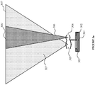
- Figure 3A illustrates an alternative embodiment of the dual mode camera configuration, illustrated in Figure 3 , wherein first optical assembly 304 and second optical assembly 305 are respectively interposed in front of first image capture region 302 of image sensor 301, and second image capture region 303 of image sensor 301 such that they both have the same working distance (i.e. their respective object planes 306' and 307' are at the same distance from the image sensor, thereby configuring both first image capture region 302 and second image capture region 303 for acquiring in-focus images of objects positioned at the same object plane).
- optical assemblies 304 and 305 may be configured to provide different angular fields of view and/or resolution, for image acquisition.
- optical assemblies 304 and 305 may include magnification and / or optical filtering properties.
- second optical assembly 305 may be configured for acquiring for image processing, an image of a subject's face positioned at object plane 307', while first optical assembly 304 may be configured for acquiring for image processing, and image of the subject's eye or iris, positioned within the narrower angular field of view of first optical assembly 304.
- the mobile device may have only a single optical assembly, but may have multiple refractive optical elements (such as plano-parallel optical elements), interposed between the image sensor and the optical assembly, each refractive optical element having a different thickness or refractive index or both - and which refractive optical elements serve to alter the effective image distance of the optical assembly.
- refractive optical elements such as plano-parallel optical elements
- Figure 4 illustrates another embodiment of a dual mode camera configuration.
- Positioned between image sensor 401 and the intended object positions are optical assembly 404.
- a first refractive optical element 402 is interposed between optical assembly 404 and a first region 409 of image sensor 401.
- a second refractive optical element 403 is interposed between optical assembly 404 and a second region 410 of image sensor 401.
- the first and second refractive optical elements 402 and 403 may respectively be configured such that they differentially alter the image distance of the optical assembly without altering the focal length of the lens assembly or the image plane (position of the image sensor relative to the lens assembly). Accordingly, first refractive optical element 402 effects a first image distance for the optical assembly 404 while second refractive optical element 403 effects a second image distance for the optical assembly 404.
- refractive optical element 403 effects a first image distance for the optical assembly such that, when an object is positioned within field of view 405 and at distance D1 from image sensor 401, an in-focus image of the object is formed on the second part 410 of image sensor 401.
- refractive optical element 402 is configured to effect a second image distance for the optical assembly such that, when an object is positioned within field of view 406 and at distance D2 from image sensor 401, an in-focus image of the object is formed on the first part 409 of image sensor 401.
- one of the refractive optical elements is specifically configured to ensure an appropriate image distance for iris image capture.
- the optical assembly 404 is configured to form an in-focus image of an object at a first object plane, on a first region of the image sensor, while the optical assembly in combination with the refractive optical element forms an in-focus image of an object at a second object plane, on a second region of the image sensor.
- the optical assembly and refractive optical elements may be positioned so as to have a transition area - wherein for image clarity, images of objects positioned within the transition area are disregarded during image capture or image parsing or image rendering. It would however be understood that embodiments without a transition area are entirely implementable as well.
- the invention can selectively record information depending on whether the camera is in a first image capture mode or in a second image capture mode.
- image data from pixels within the first image capture region may be used while image data from second image capture region is ignored.
- image data from pixels in the second image capture region is used while image date from the first image capture region is ignored.
- Switching between modes and selective parsing of pixel data may be accomplished directly by appropriate assertion of control signals by control circuitry during pixel readout. Equally, selective parsing may be accomplished subsequently after all image data is read from the pixel array, or may even be achieved by imaging software after image rendering.
- the two refractive optical elements 402 and 403 may be discrete elements or can be integrated into a unitary element having two optical regions, each region having configurations corresponding to the optical elements 402 and 403.
- the object plane may be altered without altering focal length of the lens assembly or the image plane (position of the image sensor).
- the first and second optical assemblies of Figures 3 , 3A and 4 may each comprise at least one of a lens or an optical filter.
- the first optical assembly may be interpositioned between the first image capture region and a third optical assembly.
- the second optical assembly may be interpositioned between the second image capture region and third optical assembly.
- the third optical assembly may be non-substitutably interposed between the image sensor and the first and second fields of view.
- the first optical assembly may be configured to confer upon the imaging apparatus, a first set of image capture properties corresponding to the first field of view.
- the second optical assembly may be configured to confer upon the imaging apparatus, a second set of image capture properties corresponding to the second field of view.
- the first set of image capture properties may differ from the second set of image capture properties - and in an embodiment, may differ on the basis of one or more of field of view, focus, focal length, depth of field, optical filtering properties, magnification, modulation transfer function (MTF), position of a principal plane of an optical assembly, or position of a focal plane of an optical assembly.
- MTF modulation transfer function
- the first optical assembly or the second optical assembly may comprise one or more of an infra-red pass filter, a narrow band filter, an infra-red cut filter, a refractive optical element, or a plano-parallel refractive element.
- image sensor of Figures 3 , 3A and 4 have been illustrated as a unitary image sensor having a first and second image capture region, the same function may equally be achieved by integrating or positioning more than one discretely formed image sensors adjacent to each other. Additionally, while the illustrated embodiments each show components for two image capture modes, the invention equally contemplates more than two image capture modes by adding additional optical assemblies or additional refractive optical elements or additional image sensors.
- each of the above arrangements for dual mode image capture may be used to switch between iris image capture mode and non-iris image capture mode.
- the above arrangements are not limited in application to switching between iris image capture and non-iris image capture, and may instead be used to configure a mobile device camera to switch between any two or more different image capture modes which are capable of being achieved by changing one or more of object distance, image distance, focal length, field of view, depth of field or filtering properties.
- Figure 5 illustrates an exemplary processing system in which various embodiments of the image processing apparatus of Figure 1 , or the control processor discussed in connect in with Figures 3 and 4 may be implemented.
- the system 502 comprises at-least one processor 504 and at-least one memory 506.
- the processor 504 executes program instructions and may be a real processor.
- the processor 504 may also be a virtual processor.
- the computer system 502 is not intended to suggest any limitation as to scope of use or functionality of described embodiments.
- the computer system 802 may include, but not limited to, one or more of a general-purpose computer, a programmed microprocessor, a micro-controller, an integrated circuit, and other devices or arrangements of devices that are capable of implementing the steps that constitute the method of the present invention.
- the memory 506 may store software for implementing various embodiments of the present invention.
- the computer system 502 may have additional components.
- the computer system 502 includes one or more communication channels 508, one or more input devices 510, one or more output devices 512, and storage 514.
- An interconnection mechanism such as a bus, controller, or network, interconnects the components of the computer system 802.
- operating system software (not shown) provides an operating environment for various softwares executing in the computer system 502, and manages different functionalities of the components of the computer system 502.
Landscapes
- Health & Medical Sciences (AREA)
- Engineering & Computer Science (AREA)
- Physics & Mathematics (AREA)
- Life Sciences & Earth Sciences (AREA)
- General Health & Medical Sciences (AREA)
- General Physics & Mathematics (AREA)
- Ophthalmology & Optometry (AREA)
- Multimedia (AREA)
- Surgery (AREA)
- Public Health (AREA)
- Medical Informatics (AREA)
- Molecular Biology (AREA)
- Biophysics (AREA)
- Animal Behavior & Ethology (AREA)
- Heart & Thoracic Surgery (AREA)
- Biomedical Technology (AREA)
- Veterinary Medicine (AREA)
- Theoretical Computer Science (AREA)
- Human Computer Interaction (AREA)
- Optics & Photonics (AREA)
- Pathology (AREA)
- Toxicology (AREA)
- Signal Processing (AREA)
- Studio Devices (AREA)
- Image Input (AREA)
- Measurement Of The Respiration, Hearing Ability, Form, And Blood Characteristics Of Living Organisms (AREA)
- Lenses (AREA)
- Blocking Light For Cameras (AREA)
- Cameras In General (AREA)
Claims (15)
- Bildgebungsvorrichtung (102), die sich zumindest teilweise in einem Gehäuse einer mobilen Vorrichtung befindet und konfiguriert ist für mehrere Bilderfassungsmodi, die Bildgebungsvorrichtung umfassend:einen Bildsensor (301, 401) umfassend eine Bildgebungsoberfläche;eine erste optische Baugruppe (304, 402), die über einem ersten Bilderfassungsbereich (302, 409) der Bildgebungsoberfläche platziert ist und ein erstes Sichtfeld (306, 406) definiert, wobei die erste optische Baugruppe Bilder von jeder Objektebene innerhalb des ersten Sichtfelds auf dem ersten Bilderfassungsbereich abbildet; undeine zweite optische Baugruppe (305, 403), die über einem zweiten Bilderfassungsbereich (303, 410) der Bildgebungsoberfläche platziert ist und ein zweites Sichtfeld (307, 405) definiert, wobei die zweite optische Baugruppe Bilder von jeder Objektebene innerhalb des zweiten Sichtfelds auf dem zweiten Bilderfassungsbereich abbildet und wobei die ersten und zweiten Bilderfassungsbereiche voneinander unterscheidbare Bereiche an der Bildgebungsoberfläche sind; undeine Steuervorrichtung, konfiguriert zur:Verarbeitung der Bilddaten aus Pixeln innerhalb des ersten Bilderfassungsbereichs in Reaktion auf die Auslösung eines ersten Bilderfassungsmodus; undVerarbeitung der Bilddaten aus Pixeln innerhalb des zweiten Bilderfassungsbereichs in Reaktion auf die Auslösung eines zweiten Bilderfassungsmodus.
- Bildgebungsvorrichtung nach Anspruch 1, wobei die erste optische Baugruppe und die zweite optische Baugruppe jeweils mindestens eine Linse oder einen optischen Filter umfassen.
- Bildgebungsvorrichtung nach Anspruch 1, wobei die erste optische Baugruppe zwischen dem ersten Bilderfassungsbereich und einer dritten optischen Baugruppe platziert ist, die nicht ersetzbar zwischen dem Bildsensor und den ersten und zweiten Sichtfeldern eingesetzt ist, oder die zweite optische Baugruppe zwischen dem zweiten Bilderfassungsbereich und einer dritten optischen Baugruppe platziert ist, die nicht ersetzbar zwischen dem Bildsensor und dem ersten und zweiten Sichtfeld eingesetzt ist.
- Bildgebungsvorrichtung nach Anspruch 1, wobei die erste optische Baugruppe einen ersten Satz Bilderfassungseigenschaften, die dem ersten Sichtfeld entsprechen, an die Bildgebungsvorrichtung überträgt, wobei sich der erste Satz Bilderfassungseigenschaften von einem zweiten Satz Bilderfassungseigenschaften unterscheidet, der durch die zweite optische Baugruppe dem zweiten Sichtfeld entsprechend an die Bildgebungsvorrichtung übertragen wird, und wobei sich der erste Satz der Bilderfassungseigenschaften von dem zweiten Satz der Bilderfassungseigenschaften auf der Grundlage von einem oder mehreren der Elemente Sichtfeld, Fokus, Brennweite, Tiefenschärfe, optische Filtereigenschaften, Vergrößerung, Modulationstransferfunktion (MTF), Position einer Hauptebene einer optischen Baugruppe oder Position einer Brennebene einer optischen Baugruppe unterscheidet.
- Bildgebungsvorrichtung nach Anspruch 1, wobei die erste optische Baugruppe oder die zweite optische Baugruppe eines oder mehrere der Elemente Infrarot-Pass-Filter, Schmalbandfilter, Infrarot-Cut-Filter, refraktives optisches Element oder pianoparalleles refraktives Element umfasst.
- Bildgebungsvorrichtung nach Anspruch 1, wobei entweder der erste Bilderfassungsmodus oder der zweite Bilderfassungsmodus für die Irisabbildung optimiert ist.
- Bildgebungsvorrichtung nach Anspruch 1, wobei der erste Bilderfassungsbereich und der zweite Bilderfassungsbereich durch einen Übergangsbereich voneinander getrennt sind, wobei Pixeldaten von innerhalb des Übergangsbereichs während der Bilderfassung, dem Bildparsen oder Bildrendern verworfen werden.
- Bildgebungsvorrichtung nach Anspruch 1, wobei die Steuervorrichtung konfiguriert ist, während eines der Vorgänge Bilderfassung, Bildparsen oder Bildrendern selektiv Bilddaten von innerhalb des ersten Bilderfassungsbereichs oder des zweiten Bilderfassungsbereichs zu verarbeiten.
- Bildgebungsvorrichtung nach Anspruch 6, wobei die Steuervorrichtung konfiguriert ist, auf Auslösung des ersten Bilderfassungsmodus zu reagieren durch:Verarbeitung eines ersten Satzes Bilddaten, der von Pixeln innerhalb des ersten Bilderfassungsbereichs erhalten wird, und eines zweiten Satzes Bilddaten, der von Pixeln innerhalb des zweiten Bilderfassungsbereichs erhalten wird;Rendern eines Bilds auf Grundlage entweder des ersten Satzes Bilddaten oder des zweiten Satzes Bilddaten aus Pixeln zur Anzeige für einen Bediener;Nutzung des anderen des ersten Satzes Bilddaten oder des zweiten Satzes Bilddaten zum:Vergleich der Irisinformationen innerhalb des ersten oder zweiten Satzes Bilddaten mit den gespeicherten Irisinformationen, die mindestens einer Iris entsprechen; undRendern einer Entscheidung über die Übereinstimmung oder einer Entscheidung über die Nichtübereinstimmung auf Grundlage einer Ausgabe des Vergleichs.
- Verfahren zum Ermöglichen mehrerer Bilderfassungsmodi in der Bildgebungsvorrichtung (102), wobei sich die Bildgebungsvorrichtung zumindest teilweise in einem Gehäuse einer mobilen Vorrichtung befindet, das Verfahren umfassend:Definition eines ersten Bilderfassungsbereichs (302, 409) und eines zweiten Bilderfassungsbereichs (303, 410) innerhalb der Bildgebungsoberfläche für einen Bildsensor (301, 401) der eine Bildgebungsoberfläche umfasst;Platzierung einer ersten optischen Baugruppe (304, 402) über dem ersten Bilderfassungsbereich, wobei die erste optische Baugruppe ein erstes Sichtfeld (306, 406) definiert, und jede Objektebene innerhalb des ersten Sichtfelds auf dem ersten Bilderfassungsbereich abbildet;Platzierung einer zweiten optischen Baugruppe (305, 403) über dem zweiten Bilderfassungsbereich, wobei die zweite optische Baugruppe ein zweites Sichtfeld (307, 405) definiert und jede Objektebene innerhalb des zweiten Sichtfelds auf dem zweiten Bilderfassungsbereich abbildet, und wobei die ersten und zweiten Bilderfassungsregionen voneinander unterscheidbare Regionen an der Bildgebungsoberfläche sind; undKonfiguration der Steuervorrichtung zur:Verarbeitung der Bilddaten aus Pixeln innerhalb des ersten Bilderfassungsbereichs in Reaktion auf die Auslösung eines ersten Bilderfassungsmodus; undVerarbeitung der Bilddaten aus Pixeln innerhalb des zweiten Bilderfassungsbereichs in Reaktion auf die Auslösung eines zweiten Bilderfassungsmodus.
- Verfahren nach Anspruch 10, wobei die erste optische Baugruppe zwischen dem ersten Bilderfassungsbereich und einer dritten optischen Baugruppe platziert ist, die nicht ersetzbar zwischen dem Bildsensor und den ersten und zweiten Sichtfeldern eingesetzt ist, oder die zweite optische Baugruppe zwischen dem zweiten Bilderfassungsbereich und einer dritten optischen Baugruppe platziert ist, die nicht ersetzbar zwischen dem Bildsensor und dem ersten und zweiten Sichtfeld eingesetzt ist.
- Verfahren nach Anspruch 10, wobei die erste optische Baugruppe gewählt ist, um an die Bildgebungsvorrichtung einen ersten Satz Bilderfassungseigenschaften zu übertragen, die dem ersten Sichtfeld entsprechen, wobei sich der erste Satz Bilderfassungseigenschaften von einem zweiten Satz Bilderfassungseigenschaften unterscheidet, der durch die gewählte zweite optische Baugruppe, die dem zweiten Sichtfeld entspricht, an die Bildgebungsvorrichtung übertragen wird, und wobei die erste und zweite optische Baugruppe so gewählt sind, dass sich der erste Satz der Bilderfassungseigenschaften von dem zweiten Satz der Bilderfassungseigenschaften auf der Grundlage von einem oder mehreren der Elemente Sichtfeld, Fokus, Brennweite, Tiefenschärfe, optische Filtereigenschaften, Vergrößerung, Modulationstransferfunktion (MTF), Position einer Hauptebene einer optischen Baugruppe oder Position einer Brennebene einer optischen Baugruppe unterscheidet.
- Verfahren nach Anspruch 10, umfassend die Optimierung entweder des ersten Bilderfassungsmodus oder des zweiten Bilderfassungsmodus für die Irisabbildung.
- Verfahren nach Anspruch 10, wobei die Definition des ersten Bilderfassungsbereichs und des zweiten Bilderfassungsbereichs die Definition eines Übergangsbereichs, die den ersten und den zweiten Bilderfassungsbereich voneinander trennt, und die Konfiguration der Steuervorrichtung zum Verwerfen der Pixeldaten innerhalb des Übergangsbereichs während der Bilderfassung, dem Bildparsen oder dem Bildrendern umfasst.
- Verfahren nach Anspruch 13, wobei die Steuervorrichtung konfiguriert ist, auf die Auslösung des ersten Bilderfassungsmodus zu reagieren durch:Verarbeitung eines ersten Satzes Bilddaten, der von Pixeln innerhalb des ersten Bilderfassungsbereichs erhalten wird, und eines zweiten Satzes Bilddaten, der von Pixeln innerhalb des zweiten Bilderfassungsbereichs erhalten wird;Rendern eines Bilds auf Grundlage entweder des ersten Satzes Bilddaten oder des zweiten Satzes Bilddaten aus Pixeln zur Anzeige für einen Bediener;Nutzung des anderen des ersten Satzes Bilddaten oder des zweiten Satzes Bilddaten zum:Vergleich der Irisinformationen innerhalb des ersten oder zweiten Satzes Bilddaten mit den gespeicherten Irisinformationen, die mindestens einer Iris entsprechen; undRendern einer Entscheidung über die Übereinstimmung oder einer Entscheidung über die Nichtübereinstimmung auf Grundlage einer Ausgabe des Vergleichs.
Applications Claiming Priority (2)
| Application Number | Priority Date | Filing Date | Title |
|---|---|---|---|
| US201361836444P | 2013-06-18 | 2013-06-18 | |
| PCT/US2014/042836 WO2014205021A1 (en) | 2013-06-18 | 2014-06-18 | Multiple mode image acquisition for iris imaging |
Publications (3)
| Publication Number | Publication Date |
|---|---|
| EP3011495A1 EP3011495A1 (de) | 2016-04-27 |
| EP3011495A4 EP3011495A4 (de) | 2017-01-25 |
| EP3011495B1 true EP3011495B1 (de) | 2018-11-07 |
Family
ID=52105199
Family Applications (3)
| Application Number | Title | Priority Date | Filing Date |
|---|---|---|---|
| EP14814309.2A Withdrawn EP3010392A4 (de) | 2013-06-18 | 2014-06-18 | Irisbildgebungsvorrichtung und verfahren zur konfiguration einer irisbildgebungsvorrichtung |
| EP14814311.8A Not-in-force EP3011495B1 (de) | 2013-06-18 | 2014-06-18 | Erfassung multimodaler bilder zur irisabbildung |
| EP14814540.2A Active EP3010393B1 (de) | 2013-06-18 | 2014-06-18 | Optimierte bildgebungsvorrichtung für irisabbildung |
Family Applications Before (1)
| Application Number | Title | Priority Date | Filing Date |
|---|---|---|---|
| EP14814309.2A Withdrawn EP3010392A4 (de) | 2013-06-18 | 2014-06-18 | Irisbildgebungsvorrichtung und verfahren zur konfiguration einer irisbildgebungsvorrichtung |
Family Applications After (1)
| Application Number | Title | Priority Date | Filing Date |
|---|---|---|---|
| EP14814540.2A Active EP3010393B1 (de) | 2013-06-18 | 2014-06-18 | Optimierte bildgebungsvorrichtung für irisabbildung |
Country Status (6)
| Country | Link |
|---|---|
| US (3) | US9442273B2 (de) |
| EP (3) | EP3010392A4 (de) |
| JP (4) | JP2016533566A (de) |
| KR (4) | KR101831973B1 (de) |
| CN (3) | CN105473057B (de) |
| WO (3) | WO2014205021A1 (de) |
Families Citing this family (23)
| Publication number | Priority date | Publication date | Assignee | Title |
|---|---|---|---|---|
| US8485442B2 (en) | 2009-07-02 | 2013-07-16 | Biometric Payment Solutions | Electronic transaction verification system with biometric authentication |
| CN105473057B (zh) * | 2013-06-18 | 2018-05-08 | 达美生物识别科技有限公司 | 用于虹膜成像的优化成像装置 |
| KR102287751B1 (ko) | 2014-09-25 | 2021-08-09 | 삼성전자 주식회사 | 전자 장치의 홍채 인식 방법 및 장치 |
| US9465988B1 (en) * | 2014-12-17 | 2016-10-11 | Amazon Technologies, Inc. | Camera and illuminator for iris imaging in cell phones and tablets |
| US10074011B2 (en) | 2015-01-20 | 2018-09-11 | Eyelock Llc | Lens system for high quality visible image acquisition and infra-red iris image acquisition |
| CN106470299B (zh) * | 2015-08-18 | 2022-12-23 | 杭州海康机器人股份有限公司 | 镜头、摄像机、包裹检测系统和图像处理方法 |
| US10579871B2 (en) | 2016-02-03 | 2020-03-03 | Hefei Xu | Biometric composite imaging system and method reusable with visible light |
| WO2017161520A1 (zh) * | 2016-03-23 | 2017-09-28 | 徐鹤菲 | 支持近红外光与可见光成像的复合成像系统和移动终端 |
| US10547829B2 (en) | 2016-06-16 | 2020-01-28 | Samsung Electronics Co., Ltd. | Image detecting device and image detecting method using the same |
| KR102732412B1 (ko) * | 2016-07-29 | 2024-11-22 | 삼성전자주식회사 | 옵티칼 렌즈 어셈블리 및 이를 포함한 전자 장치 |
| CN106529436B (zh) * | 2016-10-25 | 2020-03-17 | 徐鹤菲 | 一种身份一致性认证方法、装置和移动终端 |
| CN106444222A (zh) * | 2016-11-22 | 2017-02-22 | 宁波舜宇光电信息有限公司 | 一种用于虹膜识别的摄像头模组及使用该模组的设备 |
| KR102806357B1 (ko) | 2016-12-20 | 2025-05-15 | 삼성전자주식회사 | 홍채 인식 기능 운용 방법 및 이를 지원하는 전자 장치 |
| CN106618478A (zh) * | 2017-01-16 | 2017-05-10 | 中国科学院上海光学精密机械研究所 | 照明主光线共光路的手持式眼底照相机 |
| CN107368775A (zh) | 2017-04-21 | 2017-11-21 | 阿里巴巴集团控股有限公司 | 一种虹膜识别过程中的预览方法及装置 |
| CN107886079A (zh) * | 2017-11-22 | 2018-04-06 | 北京旷视科技有限公司 | 对象识别方法、装置及系统 |
| CN108108708A (zh) * | 2017-12-29 | 2018-06-01 | 徐鹤菲 | 支持多光谱生物特征的复合成像系统及移动终端 |
| US11209633B2 (en) * | 2018-02-26 | 2021-12-28 | Fotonation Limited | Iris image acquisition system |
| US11227155B2 (en) | 2019-01-23 | 2022-01-18 | Alclear, Llc | Remote biometric identification and lighting |
| KR102868992B1 (ko) | 2019-10-10 | 2025-10-10 | 삼성전자주식회사 | 줌 가능한 이미지 센서 및 이미지 센싱 방법 |
| CN111432126A (zh) * | 2020-03-31 | 2020-07-17 | 浙江大华技术股份有限公司 | 一种智能识别方法,装置、摄像机及存储介质 |
| US12470842B2 (en) * | 2022-06-10 | 2025-11-11 | Dell Products L.P. | Multifocal camera by refractive insertion and removal mechanism |
| US12413837B2 (en) | 2023-06-22 | 2025-09-09 | Dell Products L.P. | Information handling system camera multi-filter ICR within a defined focal distance |
Family Cites Families (47)
| Publication number | Priority date | Publication date | Assignee | Title |
|---|---|---|---|---|
| JPS57125918A (en) * | 1981-01-30 | 1982-08-05 | Olympus Optical Co Ltd | Microscope |
| US4871238A (en) * | 1986-03-06 | 1989-10-03 | Canon Kabushiki Kaisha | Photographic optical device with variable magnification |
| JPH07184102A (ja) * | 1993-12-24 | 1995-07-21 | Sharp Corp | 撮像装置 |
| JP2002514098A (ja) * | 1996-08-25 | 2002-05-14 | センサー インコーポレイテッド | 虹彩取得用イメージのための装置 |
| US6473231B2 (en) * | 1997-03-18 | 2002-10-29 | Canon Kabushiki Kaisha | Variable magnification optical system having image stabilizing function |
| US6289113B1 (en) | 1998-11-25 | 2001-09-11 | Iridian Technologies, Inc. | Handheld iris imaging apparatus and method |
| KR100373850B1 (ko) * | 2000-10-07 | 2003-02-26 | 주식회사 큐리텍 | 홍채를 이용한 신원 확인 시스템 및 방법과 그 방법에대한 컴퓨터 프로그램 소스를 저장한 기록매체 |
| US7277561B2 (en) * | 2000-10-07 | 2007-10-02 | Qritek Co., Ltd. | Iris identification |
| JP3900282B2 (ja) * | 2002-03-14 | 2007-04-04 | ソニー株式会社 | 撮像装置及びズームレンズ |
| CN1308884C (zh) * | 2002-03-20 | 2007-04-04 | 讯宝科技公司 | 应用公共成像阵列的捕像系统和方法 |
| JP2003284141A (ja) * | 2002-03-20 | 2003-10-03 | Fuji Photo Film Co Ltd | 携帯通信端末用認証装置 |
| KR20030091173A (ko) * | 2002-05-24 | 2003-12-03 | 에버미디어 주식회사 | 홍채인식용 광학입력기 |
| JP2004347890A (ja) * | 2003-05-22 | 2004-12-09 | Sankyo Seiki Mfg Co Ltd | レンズ駆動装置、薄型カメラおよびカメラ付き携帯電話機 |
| JP2005020718A (ja) * | 2003-06-02 | 2005-01-20 | Pentax Corp | 多焦点撮像デバイス及びモバイル機器 |
| US8064647B2 (en) * | 2006-03-03 | 2011-11-22 | Honeywell International Inc. | System for iris detection tracking and recognition at a distance |
| US8049812B2 (en) * | 2006-03-03 | 2011-11-01 | Honeywell International Inc. | Camera with auto focus capability |
| JP2005242677A (ja) * | 2004-02-26 | 2005-09-08 | Ntt Comware Corp | 複合認証システムおよびその方法ならびにプログラム |
| JP2005292542A (ja) * | 2004-04-01 | 2005-10-20 | Matsushita Electric Ind Co Ltd | 目画像撮像装置および携帯端末装置 |
| JP2005287878A (ja) * | 2004-04-01 | 2005-10-20 | Matsushita Electric Ind Co Ltd | 生体判別装置および認証装置ならびに生体判別方法 |
| US7218444B2 (en) * | 2004-05-03 | 2007-05-15 | Raytheon Company | Dual-band, dual-focal-length, relayed refractive imager |
| JP2005339425A (ja) * | 2004-05-31 | 2005-12-08 | Sanyo Electric Co Ltd | 本人認証装置 |
| JP4455216B2 (ja) * | 2004-08-06 | 2010-04-21 | キヤノン株式会社 | 検出装置 |
| JP2006078713A (ja) * | 2004-09-09 | 2006-03-23 | Hitachi High-Tech Electronics Engineering Co Ltd | ワークの識別情報読取装置および読取方法 |
| JP2006093934A (ja) * | 2004-09-22 | 2006-04-06 | Nec Corp | カメラ付き携帯電話端末及びその認証方法 |
| KR200383808Y1 (ko) | 2005-01-21 | 2005-05-10 | 주식회사 큐리텍 | 홍채 이미지 획득 카메라 |
| JP4622541B2 (ja) * | 2005-01-25 | 2011-02-02 | 沖電気工業株式会社 | 虹彩撮影装置 |
| JP4944393B2 (ja) * | 2005-05-25 | 2012-05-30 | キヤノン株式会社 | 撮像装置 |
| US7417673B2 (en) * | 2005-05-31 | 2008-08-26 | Nokia Corporation | Optical and digital zooming for an imaging device |
| JP2006350410A (ja) * | 2005-06-13 | 2006-12-28 | Matsushita Electric Ind Co Ltd | 眼画像撮影装置および認証装置 |
| JP4622763B2 (ja) * | 2005-09-14 | 2011-02-02 | 日本電気株式会社 | 携帯通信端末装置及び認証方法 |
| WO2007103834A1 (en) * | 2006-03-03 | 2007-09-13 | Honeywell International, Inc. | Indexing and database search system |
| WO2008016724A2 (en) * | 2006-03-03 | 2008-02-07 | Honeywell International, Inc. | An iris recognition system having image quality metrics |
| KR100738803B1 (ko) * | 2006-05-04 | 2007-07-12 | 엘지이노텍 주식회사 | 하나의 이미지 센서로 듀얼 카메라 기능을 구현하는 카메라모듈 및 휴대용 단말기 |
| US8121356B2 (en) * | 2006-09-15 | 2012-02-21 | Identix Incorporated | Long distance multimodal biometric system and method |
| EP1978394A1 (de) * | 2007-04-06 | 2008-10-08 | Global Bionic Optics Pty Ltd. | Optisches System zum Vergrößern der Tiefenschärfe |
| CN101334509B (zh) * | 2007-06-25 | 2010-12-08 | 鸿富锦精密工业(深圳)有限公司 | 便携式电子装置 |
| EP2198552A1 (de) | 2007-09-28 | 2010-06-23 | Eye Controls, LLC. | Systeme und verfahren zur biometrischen identifikation |
| JP2009199200A (ja) | 2008-02-20 | 2009-09-03 | Oki Electric Ind Co Ltd | 携帯型虹彩認証装置 |
| US8090246B2 (en) * | 2008-08-08 | 2012-01-03 | Honeywell International Inc. | Image acquisition system |
| US8719584B2 (en) * | 2010-10-26 | 2014-05-06 | Bi2 Technologies, LLC | Mobile, wireless hand-held biometric capture, processing and communication system and method for biometric identification |
| KR20120068655A (ko) * | 2010-12-19 | 2012-06-27 | 김인선 | 무선통신장치를 이용하여 양질의 홍채 및 피사체 영상을 편리하게 촬영하기 위한 방법 및 한 개의 밴드패스필터로 가시광선과 근적외선 일부영역을 투과시키는 카메라 장치 |
| RU2589859C2 (ru) * | 2011-02-17 | 2016-07-10 | АЙЛОК ЭлЭлСи | Эффективный способ и система для получения данных изображения сцены и изображения радужной оболочки с использованием одного датчика |
| RU2623795C2 (ru) * | 2011-08-22 | 2017-06-29 | АЙЛОК ЭлЭлСи | Системы и способы для захвата безартефактных изображений |
| US10110834B2 (en) * | 2011-11-07 | 2018-10-23 | Raytheon Company | Hadamard enhanced sensors |
| US8437513B1 (en) | 2012-08-10 | 2013-05-07 | EyeVerify LLC | Spoof detection for biometric authentication |
| CN105473057B (zh) * | 2013-06-18 | 2018-05-08 | 达美生物识别科技有限公司 | 用于虹膜成像的优化成像装置 |
| US9582716B2 (en) * | 2013-09-09 | 2017-02-28 | Delta ID Inc. | Apparatuses and methods for iris based biometric recognition |
-
2014
- 2014-06-18 CN CN201480045615.4A patent/CN105473057B/zh active Active
- 2014-06-18 KR KR1020167000905A patent/KR101831973B1/ko not_active Expired - Fee Related
- 2014-06-18 CN CN201480045625.8A patent/CN105474222B/zh active Active
- 2014-06-18 JP JP2016521529A patent/JP2016533566A/ja active Pending
- 2014-06-18 WO PCT/US2014/042836 patent/WO2014205021A1/en not_active Ceased
- 2014-06-18 EP EP14814309.2A patent/EP3010392A4/de not_active Withdrawn
- 2014-06-18 WO PCT/US2014/042838 patent/WO2014205022A1/en not_active Ceased
- 2014-06-18 CN CN201480045682.6A patent/CN105473058A/zh active Pending
- 2014-06-18 EP EP14814311.8A patent/EP3011495B1/de not_active Not-in-force
- 2014-06-18 JP JP2016521528A patent/JP2016527769A/ja active Pending
- 2014-06-18 WO PCT/US2014/042834 patent/WO2014205020A1/en not_active Ceased
- 2014-06-18 US US14/899,885 patent/US9442273B2/en active Active
- 2014-06-18 JP JP2016521527A patent/JP2016533523A/ja active Pending
- 2014-06-18 EP EP14814540.2A patent/EP3010393B1/de active Active
- 2014-06-18 KR KR1020167001188A patent/KR102150344B1/ko active Active
- 2014-06-18 KR KR1020167000793A patent/KR102305263B1/ko active Active
- 2014-06-18 KR KR1020187004884A patent/KR102043866B1/ko active Active
- 2014-06-18 US US14/899,672 patent/US10018804B2/en active Active
-
2015
- 2015-08-25 US US14/835,309 patent/US9366843B2/en active Active
-
2018
- 2018-03-13 JP JP2018045565A patent/JP2018128687A/ja active Pending
Non-Patent Citations (1)
| Title |
|---|
| None * |
Also Published As
Similar Documents
| Publication | Publication Date | Title |
|---|---|---|
| EP3011495B1 (de) | Erfassung multimodaler bilder zur irisabbildung | |
| US9300858B2 (en) | Control device and storage medium for controlling capture of images | |
| US20160335495A1 (en) | Apparatus and method for acquiring image for iris recognition using distance of facial feature | |
| AU2017217930B2 (en) | Systems and methods for HDR video capture with a mobile device | |
| JP6564271B2 (ja) | 撮像装置及び画像処理方法、プログラム、並びに記憶媒体 | |
| CN103052960A (zh) | 失焦状况下的对象检测和识别 | |
| CN107111009A (zh) | 用于图像获取装置的光学系统 | |
| KR20150037628A (ko) | 생체인식 카메라 | |
| WO2019036751A1 (en) | ENHANCED VIDEO-BASED DRIVER MONITORING USING PHASE DETECTION SENSORS | |
| US20170330025A1 (en) | Image processing apparatus, image processing method, and non-transitory computer-readable storage medium | |
| CN104680128A (zh) | 一种基于四维分析的生物特征识别方法和系统 | |
| KR102171018B1 (ko) | 캡쳐 볼륨 공간 확보를 통한 안면 및 홍채 인식 방법 및 시스템 | |
| KR101767941B1 (ko) | 일반 촬영 및 홍채인식 촬영이 가능한 겸용 카메라 | |
| CN107147845B (zh) | 对焦方法、装置和终端设备 | |
| KR102209613B1 (ko) | 보조 카메라를 이용한 단말기에서의 홍채 영상 획득 장치 및 그 방법 | |
| TW201616167A (zh) | 取像模組 |
Legal Events
| Date | Code | Title | Description |
|---|---|---|---|
| PUAI | Public reference made under article 153(3) epc to a published international application that has entered the european phase |
Free format text: ORIGINAL CODE: 0009012 |
|
| 17P | Request for examination filed |
Effective date: 20151217 |
|
| AK | Designated contracting states |
Kind code of ref document: A1 Designated state(s): AL AT BE BG CH CY CZ DE DK EE ES FI FR GB GR HR HU IE IS IT LI LT LU LV MC MK MT NL NO PL PT RO RS SE SI SK SM TR |
|
| AX | Request for extension of the european patent |
Extension state: BA ME |
|
| DAX | Request for extension of the european patent (deleted) | ||
| A4 | Supplementary search report drawn up and despatched |
Effective date: 20161222 |
|
| RIC1 | Information provided on ipc code assigned before grant |
Ipc: G06F 21/32 20130101AFI20161216BHEP |
|
| GRAP | Despatch of communication of intention to grant a patent |
Free format text: ORIGINAL CODE: EPIDOSNIGR1 |
|
| STAA | Information on the status of an ep patent application or granted ep patent |
Free format text: STATUS: GRANT OF PATENT IS INTENDED |
|
| INTG | Intention to grant announced |
Effective date: 20180605 |
|
| GRAS | Grant fee paid |
Free format text: ORIGINAL CODE: EPIDOSNIGR3 |
|
| GRAA | (expected) grant |
Free format text: ORIGINAL CODE: 0009210 |
|
| STAA | Information on the status of an ep patent application or granted ep patent |
Free format text: STATUS: THE PATENT HAS BEEN GRANTED |
|
| AK | Designated contracting states |
Kind code of ref document: B1 Designated state(s): AL AT BE BG CH CY CZ DE DK EE ES FI FR GB GR HR HU IE IS IT LI LT LU LV MC MK MT NL NO PL PT RO RS SE SI SK SM TR |
|
| REG | Reference to a national code |
Ref country code: GB Ref legal event code: FG4D |
|
| REG | Reference to a national code |
Ref country code: CH Ref legal event code: EP Ref country code: AT Ref legal event code: REF Ref document number: 1062951 Country of ref document: AT Kind code of ref document: T Effective date: 20181115 |
|
| REG | Reference to a national code |
Ref country code: DE Ref legal event code: R096 Ref document number: 602014035687 Country of ref document: DE |
|
| REG | Reference to a national code |
Ref country code: IE Ref legal event code: FG4D |
|
| REG | Reference to a national code |
Ref country code: NL Ref legal event code: MP Effective date: 20181107 |
|
| REG | Reference to a national code |
Ref country code: LT Ref legal event code: MG4D |
|
| REG | Reference to a national code |
Ref country code: AT Ref legal event code: MK05 Ref document number: 1062951 Country of ref document: AT Kind code of ref document: T Effective date: 20181107 |
|
| PG25 | Lapsed in a contracting state [announced via postgrant information from national office to epo] |
Ref country code: IS Free format text: LAPSE BECAUSE OF FAILURE TO SUBMIT A TRANSLATION OF THE DESCRIPTION OR TO PAY THE FEE WITHIN THE PRESCRIBED TIME-LIMIT Effective date: 20190307 Ref country code: ES Free format text: LAPSE BECAUSE OF FAILURE TO SUBMIT A TRANSLATION OF THE DESCRIPTION OR TO PAY THE FEE WITHIN THE PRESCRIBED TIME-LIMIT Effective date: 20181107 Ref country code: BG Free format text: LAPSE BECAUSE OF FAILURE TO SUBMIT A TRANSLATION OF THE DESCRIPTION OR TO PAY THE FEE WITHIN THE PRESCRIBED TIME-LIMIT Effective date: 20190207 Ref country code: LT Free format text: LAPSE BECAUSE OF FAILURE TO SUBMIT A TRANSLATION OF THE DESCRIPTION OR TO PAY THE FEE WITHIN THE PRESCRIBED TIME-LIMIT Effective date: 20181107 Ref country code: HR Free format text: LAPSE BECAUSE OF FAILURE TO SUBMIT A TRANSLATION OF THE DESCRIPTION OR TO PAY THE FEE WITHIN THE PRESCRIBED TIME-LIMIT Effective date: 20181107 Ref country code: LV Free format text: LAPSE BECAUSE OF FAILURE TO SUBMIT A TRANSLATION OF THE DESCRIPTION OR TO PAY THE FEE WITHIN THE PRESCRIBED TIME-LIMIT Effective date: 20181107 Ref country code: NO Free format text: LAPSE BECAUSE OF FAILURE TO SUBMIT A TRANSLATION OF THE DESCRIPTION OR TO PAY THE FEE WITHIN THE PRESCRIBED TIME-LIMIT Effective date: 20190207 Ref country code: FI Free format text: LAPSE BECAUSE OF FAILURE TO SUBMIT A TRANSLATION OF THE DESCRIPTION OR TO PAY THE FEE WITHIN THE PRESCRIBED TIME-LIMIT Effective date: 20181107 Ref country code: AT Free format text: LAPSE BECAUSE OF FAILURE TO SUBMIT A TRANSLATION OF THE DESCRIPTION OR TO PAY THE FEE WITHIN THE PRESCRIBED TIME-LIMIT Effective date: 20181107 |
|
| PG25 | Lapsed in a contracting state [announced via postgrant information from national office to epo] |
Ref country code: NL Free format text: LAPSE BECAUSE OF FAILURE TO SUBMIT A TRANSLATION OF THE DESCRIPTION OR TO PAY THE FEE WITHIN THE PRESCRIBED TIME-LIMIT Effective date: 20181107 Ref country code: SE Free format text: LAPSE BECAUSE OF FAILURE TO SUBMIT A TRANSLATION OF THE DESCRIPTION OR TO PAY THE FEE WITHIN THE PRESCRIBED TIME-LIMIT Effective date: 20181107 Ref country code: AL Free format text: LAPSE BECAUSE OF FAILURE TO SUBMIT A TRANSLATION OF THE DESCRIPTION OR TO PAY THE FEE WITHIN THE PRESCRIBED TIME-LIMIT Effective date: 20181107 Ref country code: RS Free format text: LAPSE BECAUSE OF FAILURE TO SUBMIT A TRANSLATION OF THE DESCRIPTION OR TO PAY THE FEE WITHIN THE PRESCRIBED TIME-LIMIT Effective date: 20181107 Ref country code: GR Free format text: LAPSE BECAUSE OF FAILURE TO SUBMIT A TRANSLATION OF THE DESCRIPTION OR TO PAY THE FEE WITHIN THE PRESCRIBED TIME-LIMIT Effective date: 20190208 Ref country code: PT Free format text: LAPSE BECAUSE OF FAILURE TO SUBMIT A TRANSLATION OF THE DESCRIPTION OR TO PAY THE FEE WITHIN THE PRESCRIBED TIME-LIMIT Effective date: 20190307 |
|
| PG25 | Lapsed in a contracting state [announced via postgrant information from national office to epo] |
Ref country code: CZ Free format text: LAPSE BECAUSE OF FAILURE TO SUBMIT A TRANSLATION OF THE DESCRIPTION OR TO PAY THE FEE WITHIN THE PRESCRIBED TIME-LIMIT Effective date: 20181107 Ref country code: IT Free format text: LAPSE BECAUSE OF FAILURE TO SUBMIT A TRANSLATION OF THE DESCRIPTION OR TO PAY THE FEE WITHIN THE PRESCRIBED TIME-LIMIT Effective date: 20181107 Ref country code: DK Free format text: LAPSE BECAUSE OF FAILURE TO SUBMIT A TRANSLATION OF THE DESCRIPTION OR TO PAY THE FEE WITHIN THE PRESCRIBED TIME-LIMIT Effective date: 20181107 Ref country code: PL Free format text: LAPSE BECAUSE OF FAILURE TO SUBMIT A TRANSLATION OF THE DESCRIPTION OR TO PAY THE FEE WITHIN THE PRESCRIBED TIME-LIMIT Effective date: 20181107 |
|
| REG | Reference to a national code |
Ref country code: DE Ref legal event code: R097 Ref document number: 602014035687 Country of ref document: DE |
|
| PG25 | Lapsed in a contracting state [announced via postgrant information from national office to epo] |
Ref country code: SM Free format text: LAPSE BECAUSE OF FAILURE TO SUBMIT A TRANSLATION OF THE DESCRIPTION OR TO PAY THE FEE WITHIN THE PRESCRIBED TIME-LIMIT Effective date: 20181107 Ref country code: SK Free format text: LAPSE BECAUSE OF FAILURE TO SUBMIT A TRANSLATION OF THE DESCRIPTION OR TO PAY THE FEE WITHIN THE PRESCRIBED TIME-LIMIT Effective date: 20181107 Ref country code: RO Free format text: LAPSE BECAUSE OF FAILURE TO SUBMIT A TRANSLATION OF THE DESCRIPTION OR TO PAY THE FEE WITHIN THE PRESCRIBED TIME-LIMIT Effective date: 20181107 Ref country code: EE Free format text: LAPSE BECAUSE OF FAILURE TO SUBMIT A TRANSLATION OF THE DESCRIPTION OR TO PAY THE FEE WITHIN THE PRESCRIBED TIME-LIMIT Effective date: 20181107 |
|
| PLBE | No opposition filed within time limit |
Free format text: ORIGINAL CODE: 0009261 |
|
| STAA | Information on the status of an ep patent application or granted ep patent |
Free format text: STATUS: NO OPPOSITION FILED WITHIN TIME LIMIT |
|
| 26N | No opposition filed |
Effective date: 20190808 |
|
| PG25 | Lapsed in a contracting state [announced via postgrant information from national office to epo] |
Ref country code: SI Free format text: LAPSE BECAUSE OF FAILURE TO SUBMIT A TRANSLATION OF THE DESCRIPTION OR TO PAY THE FEE WITHIN THE PRESCRIBED TIME-LIMIT Effective date: 20181107 |
|
| PG25 | Lapsed in a contracting state [announced via postgrant information from national office to epo] |
Ref country code: MC Free format text: LAPSE BECAUSE OF FAILURE TO SUBMIT A TRANSLATION OF THE DESCRIPTION OR TO PAY THE FEE WITHIN THE PRESCRIBED TIME-LIMIT Effective date: 20181107 |
|
| REG | Reference to a national code |
Ref country code: CH Ref legal event code: PL |
|
| REG | Reference to a national code |
Ref country code: BE Ref legal event code: MM Effective date: 20190630 |
|
| PG25 | Lapsed in a contracting state [announced via postgrant information from national office to epo] |
Ref country code: TR Free format text: LAPSE BECAUSE OF FAILURE TO SUBMIT A TRANSLATION OF THE DESCRIPTION OR TO PAY THE FEE WITHIN THE PRESCRIBED TIME-LIMIT Effective date: 20181107 |
|
| PG25 | Lapsed in a contracting state [announced via postgrant information from national office to epo] |
Ref country code: IE Free format text: LAPSE BECAUSE OF NON-PAYMENT OF DUE FEES Effective date: 20190618 |
|
| PG25 | Lapsed in a contracting state [announced via postgrant information from national office to epo] |
Ref country code: CH Free format text: LAPSE BECAUSE OF NON-PAYMENT OF DUE FEES Effective date: 20190630 Ref country code: LI Free format text: LAPSE BECAUSE OF NON-PAYMENT OF DUE FEES Effective date: 20190630 Ref country code: BE Free format text: LAPSE BECAUSE OF NON-PAYMENT OF DUE FEES Effective date: 20190630 Ref country code: LU Free format text: LAPSE BECAUSE OF NON-PAYMENT OF DUE FEES Effective date: 20190618 |
|
| PG25 | Lapsed in a contracting state [announced via postgrant information from national office to epo] |
Ref country code: CY Free format text: LAPSE BECAUSE OF FAILURE TO SUBMIT A TRANSLATION OF THE DESCRIPTION OR TO PAY THE FEE WITHIN THE PRESCRIBED TIME-LIMIT Effective date: 20181107 |
|
| PG25 | Lapsed in a contracting state [announced via postgrant information from national office to epo] |
Ref country code: MT Free format text: LAPSE BECAUSE OF FAILURE TO SUBMIT A TRANSLATION OF THE DESCRIPTION OR TO PAY THE FEE WITHIN THE PRESCRIBED TIME-LIMIT Effective date: 20181107 Ref country code: HU Free format text: LAPSE BECAUSE OF FAILURE TO SUBMIT A TRANSLATION OF THE DESCRIPTION OR TO PAY THE FEE WITHIN THE PRESCRIBED TIME-LIMIT; INVALID AB INITIO Effective date: 20140618 |
|
| PG25 | Lapsed in a contracting state [announced via postgrant information from national office to epo] |
Ref country code: MK Free format text: LAPSE BECAUSE OF FAILURE TO SUBMIT A TRANSLATION OF THE DESCRIPTION OR TO PAY THE FEE WITHIN THE PRESCRIBED TIME-LIMIT Effective date: 20181107 |
|
| PGFP | Annual fee paid to national office [announced via postgrant information from national office to epo] |
Ref country code: GB Payment date: 20240627 Year of fee payment: 11 |
|
| PGFP | Annual fee paid to national office [announced via postgrant information from national office to epo] |
Ref country code: DE Payment date: 20240627 Year of fee payment: 11 |
|
| PGFP | Annual fee paid to national office [announced via postgrant information from national office to epo] |
Ref country code: FR Payment date: 20240625 Year of fee payment: 11 |
|
| REG | Reference to a national code |
Ref country code: DE Ref legal event code: R119 Ref document number: 602014035687 Country of ref document: DE |
|
| GBPC | Gb: european patent ceased through non-payment of renewal fee |
Effective date: 20250618 |
|
| PG25 | Lapsed in a contracting state [announced via postgrant information from national office to epo] |
Ref country code: GB Free format text: LAPSE BECAUSE OF NON-PAYMENT OF DUE FEES Effective date: 20250618 |
|
| PG25 | Lapsed in a contracting state [announced via postgrant information from national office to epo] |
Ref country code: DE Free format text: LAPSE BECAUSE OF NON-PAYMENT OF DUE FEES Effective date: 20260101 |
|
| PG25 | Lapsed in a contracting state [announced via postgrant information from national office to epo] |
Ref country code: FR Free format text: LAPSE BECAUSE OF NON-PAYMENT OF DUE FEES Effective date: 20250630 |