EP3011900A1 - Module d'électrode, système de succion et outil pour la surveillance de biopotentiel - Google Patents
Module d'électrode, système de succion et outil pour la surveillance de biopotentiel Download PDFInfo
- Publication number
- EP3011900A1 EP3011900A1 EP14190353.4A EP14190353A EP3011900A1 EP 3011900 A1 EP3011900 A1 EP 3011900A1 EP 14190353 A EP14190353 A EP 14190353A EP 3011900 A1 EP3011900 A1 EP 3011900A1
- Authority
- EP
- European Patent Office
- Prior art keywords
- electrode
- vacuum
- electrode module
- tool
- vacuum chamber
- Prior art date
- Legal status (The legal status is an assumption and is not a legal conclusion. Google has not performed a legal analysis and makes no representation as to the accuracy of the status listed.)
- Withdrawn
Links
- 238000012544 monitoring process Methods 0.000 title claims description 8
- 239000000463 material Substances 0.000 claims description 6
- 210000002445 nipple Anatomy 0.000 claims description 4
- 229920002725 thermoplastic elastomer Polymers 0.000 claims description 4
- 239000004743 Polypropylene Substances 0.000 claims description 3
- 229920001155 polypropylene Polymers 0.000 claims description 3
- 239000002906 medical waste Substances 0.000 claims description 2
- -1 polypropylene Polymers 0.000 claims description 2
- 241000907903 Shorea Species 0.000 claims 1
- 210000003491 skin Anatomy 0.000 description 30
- 230000033001 locomotion Effects 0.000 description 10
- 238000005299 abrasion Methods 0.000 description 5
- 239000000853 adhesive Substances 0.000 description 5
- 230000001070 adhesive effect Effects 0.000 description 5
- 239000000499 gel Substances 0.000 description 5
- 238000000034 method Methods 0.000 description 4
- 239000004033 plastic Substances 0.000 description 4
- 239000000243 solution Substances 0.000 description 4
- 230000000694 effects Effects 0.000 description 3
- 239000003792 electrolyte Substances 0.000 description 3
- 238000005259 measurement Methods 0.000 description 3
- 230000002093 peripheral effect Effects 0.000 description 3
- 230000000087 stabilizing effect Effects 0.000 description 3
- 230000035882 stress Effects 0.000 description 3
- 239000000126 substance Substances 0.000 description 3
- 241000894006 Bacteria Species 0.000 description 2
- 241000700605 Viruses Species 0.000 description 2
- 229920001940 conductive polymer Polymers 0.000 description 2
- 238000010276 construction Methods 0.000 description 2
- 238000002347 injection Methods 0.000 description 2
- 239000007924 injection Substances 0.000 description 2
- 230000003014 reinforcing effect Effects 0.000 description 2
- 230000001954 sterilising effect Effects 0.000 description 2
- 238000004659 sterilization and disinfection Methods 0.000 description 2
- 206010049119 Emotional distress Diseases 0.000 description 1
- LFQSCWFLJHTTHZ-UHFFFAOYSA-N Ethanol Chemical compound CCO LFQSCWFLJHTTHZ-UHFFFAOYSA-N 0.000 description 1
- 210000003423 ankle Anatomy 0.000 description 1
- 238000004140 cleaning Methods 0.000 description 1
- 238000011109 contamination Methods 0.000 description 1
- 230000001351 cycling effect Effects 0.000 description 1
- 230000001419 dependent effect Effects 0.000 description 1
- 229920001971 elastomer Polymers 0.000 description 1
- 238000002565 electrocardiography Methods 0.000 description 1
- 210000002615 epidermis Anatomy 0.000 description 1
- 150000002500 ions Chemical class 0.000 description 1
- 239000002184 metal Substances 0.000 description 1
- 239000002245 particle Substances 0.000 description 1
- 230000000644 propagated effect Effects 0.000 description 1
- 239000011347 resin Substances 0.000 description 1
- 229920005989 resin Polymers 0.000 description 1
- 239000004576 sand Substances 0.000 description 1
- 238000007789 sealing Methods 0.000 description 1
- 239000007921 spray Substances 0.000 description 1
- 229920001169 thermoplastic Polymers 0.000 description 1
- 229920001187 thermosetting polymer Polymers 0.000 description 1
- 239000004416 thermosoftening plastic Substances 0.000 description 1
- 210000005010 torso Anatomy 0.000 description 1
- 210000000707 wrist Anatomy 0.000 description 1
Images


Classifications
-
- A—HUMAN NECESSITIES
- A61—MEDICAL OR VETERINARY SCIENCE; HYGIENE
- A61B—DIAGNOSIS; SURGERY; IDENTIFICATION
- A61B5/00—Measuring for diagnostic purposes; Identification of persons
- A61B5/24—Detecting, measuring or recording bioelectric or biomagnetic signals of the body or parts thereof
- A61B5/25—Bioelectric electrodes therefor
- A61B5/279—Bioelectric electrodes therefor specially adapted for particular uses
- A61B5/28—Bioelectric electrodes therefor specially adapted for particular uses for electrocardiography [ECG]
-
- A—HUMAN NECESSITIES
- A61—MEDICAL OR VETERINARY SCIENCE; HYGIENE
- A61B—DIAGNOSIS; SURGERY; IDENTIFICATION
- A61B5/00—Measuring for diagnostic purposes; Identification of persons
- A61B5/68—Arrangements of detecting, measuring or recording means, e.g. sensors, in relation to patient
- A61B5/6801—Arrangements of detecting, measuring or recording means, e.g. sensors, in relation to patient specially adapted to be attached to or worn on the body surface
- A61B5/683—Means for maintaining contact with the body
- A61B5/6834—Means for maintaining contact with the body using vacuum
-
- A—HUMAN NECESSITIES
- A61—MEDICAL OR VETERINARY SCIENCE; HYGIENE
- A61B—DIAGNOSIS; SURGERY; IDENTIFICATION
- A61B5/00—Measuring for diagnostic purposes; Identification of persons
- A61B5/24—Detecting, measuring or recording bioelectric or biomagnetic signals of the body or parts thereof
- A61B5/25—Bioelectric electrodes therefor
- A61B5/251—Means for maintaining electrode contact with the body
- A61B5/252—Means for maintaining electrode contact with the body by suction
Definitions
- the present invention relates in general to electrode modules for biopotential monitoring, and in particular electrocardiogram (ECG) monitoring of the heart's electrical activity through the skin at various points on the torso, ankles and wrists.
- ECG electrocardiogram
- US 8 406 843 describes a disposable stick-on ECG monitoring electrode which does not use vacuum suction. It proposes a way to deal with problems which it describes in the fourth paragraph of column 1: "The strength and accuracy of the signals from the ECG electrodes to the monitor is dependent on motion artifacts caused by the movement of the patient's skin relative to the electrode. This movement can cause extraneous signals, shifting the desired signal baseline. Abrading the skin reduces the electrical potential and minimizes the impedance of the patient's skin, thereby reducing motions artifacts and improving the biopotential electrical signal. Typically, the patient's skin is prepared prior to applying the electrode.
- Preparatory abrasion removes a portion of the epidermis or external skin layer and is usually performed by rubbing the patient's skin with a rough surfaced material followed by cleaning the abraded area with alcohol. If the electrical potential of one or more electrodes is too great and the signal is not adequate, the electrode(s) must be removed, the site further abraded, and the electrodes (s) reapplied. This procedure is not only time consuming, but may be painful to the patient. The processes may also cause emotional distress to the patient as the patient views the skin abrading procedure.
- the proposed solution according to this prior art document US 8 406 843 is that the disposable electrode have an abrasive surface, used to sand off and prep the skin of the patient by twisting the electrode back and forth.
- the abrasive electrode can also be infused with gel which will spread over the abraded skin and decrease the impedance between the skin and the electrode surface.
- the proposed prior art solution also includes using adhesive patch to keep the electrode in place. Any procedure which requires abrasion of multiple skin locations and the use of gel and adhesive is naturally not optimal.
- Suction electrodes In addition to stick-on disposable electrodes, various suction modules are known in the art which are connected via suction hoses to a central vacuum unit and a recording and analysis unit for the electrical signals. Suction electrodes have the advantage of being easy to apply and remove and do not require abrasion of the skin or the use of adhesives.
- a disposable electrode disc or cup has a central metal electrode, which has a flat skin-contacting surface and a knob for attachment to/detachment from a block in the module, and is surrounded by a plastic disc portion with a flexible skirt to create a vacuum chamber and seal against the skin of the patient.
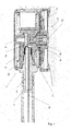
- a vacuum electrode module 1 is shown for use in a suction system together with an ECG monitor.
- Usually up to ten such vacuum electrode modules are coupled to the same suction system for ECG monitoring, each via an individual electrically conducting vacuum hose 4, which is slipped over the outer part of the nipple 4a.
- the nipple is part of the peripheral plastic shell 18.
- the inner nipple 4b is forced into the central conductive polymer block 9 in the vacuum electrode module housing 2.
- a disposable electrode unit 5 has a central electrode sensor element 6a-c, comprising a skin-contacting biopotential transducer sensor 6a and a snap connector 6b with a knob 6c which is snapped into a socket 9a in the electrically conducting block 9.
- An electrical signal conducting wire 18 within the hose 4 is connected to a contact ring 19 which is in electrical contact with the conductive polymer block 9.
- a vacuum chamber dish 7 which is made of relatively rigid plastic, in this embodiment of injection molded polypropylene thermosetting resin. Extending from the periphery of said vacuum chamber dish 7 is a circumferential lip 8 of a flexible and resilient plastic or rubber, in this embodiment of thermoplastic elastomer which has been injection molded to be permanently attached to the dish 7, which is still warm when the thermoplastic lip is molded thereto.
- This construction prevents tugging on the hose 4 and/or unevenness in the skin area from causing the chemical equilibrium of the double layer interface where the electrode sensor element meets the skin surface, to be disturbed, giving rise to motion artifacts in the ECG monitoring record.
- Fig. 2 shows such a situation where the skin area is uneven.
- the lip 8a on one side is fully compressed by the skin and the force generated by the vacuum, whereas the lip 8b on its other side is only very slightly compressed where it meets the skin, preserving the vacuum suction all around, without ever disturbing the chemical equilibrium interface where the electrode sensor element meets the skin.
- the peripheral groove 16 between the module housing 2 and the disposable electrode 5 is clearly visible.
- the lip 8 also has an interior groove 8c which facilitates folding of the lip as can be seen at 8c in Fig. 2 .
- Fig. 3 shows a typical situation where, during an exercise cycle or treadmill running stress test, the vacuum hose 4 is tugged in the direction of the arrow A.
- the force, propagated by this pulling, at the interface between the skin-contacting electrode sensor element 6a will be lateral in the direction of the arrow B, pulling the skin laterally, without any change in the Helmholtz double layer at said interface.
- the novel construction of the disposable electrode disc unit 5 with a stabilizing more rigid portion (the vacuum chamber dish 7) and a softer, flexible and resilient lip portion 8 prevents any tipping of the biopotential transducer sensor 6a in relation to the skin 12 and at the same time ensures a complete and reliable vacuum seal around the vacuum chamber.
- the forces transmitted via the hose being pulled will act coplanar to the interface between the electrode surface 6a and the skin 12. If both the vacuum chamber dish 7 and the circumferential lip 8 were made in one piece of the same flexible pliable material, pulling on the vacuum hose 4 would cause the entire module to tip changing the contact between the biopotential transducer sensor 6a and the skin 12 and giving rise to motion artifacts.
- both the vacuum chamber dish 7 and the pliable circumferential lip 8 were made in the same more rigid material the vacuum seal risks being broken due to movement or due to hair or uneven skin, which will also distort the ECG measurements or even lead to the electrode module falling off.
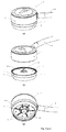
- Fig. 4 shows the entire coupled vacuum electrode module in three views: (a) a perspective view from above, (b) with the disposable electrode unit 2 detached from the vacuum electrode module housing 2 and (c) a view from below of the coupled module showing the vacuum chamber dish 7 with stabilizing and reinforcing ribs 15 and vacuum holes 14 to transmit suction from the hose 4.
- said ribs have been replaced by vacuum distribution channels.
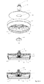
- Fig. 5(a)-(c) showing the disposable electrode unit by itself in three views: (a) an exploded view showing the skin-contacting biopotential transducer sensor 6a of the electrode sensor element, the electrically conducting snap connector 6b with knob 6c.
- a HEPA filter On top of the vacuum chamber dish 7 is, in this embodiment, a HEPA filter which will trap almost all particles, which can carry virus and bacteria.
- Fig. 5(b) shows a cross-section bisecting the reinforcing and stabilizing ribs 15.
- Fig. 5(c) shows a cross-section along a plane perpendicular thereto.
- Figs. 6, 7 and 8 show the use of a specifically designed detacher tool 20 for separating the disposable electrode unit 5 from the vacuum electrode module housing 2 and disposal of the used electrode unit 5 without the medical personnel ever having to touch the used electrode unit 5.
- Fig. 6 shows the detacher tool 20 which has two rails 21 spaced the width of the disposable electrode unit. As can be seen in Figs. 7 and 8 , the rails 21 each have a ridge 23 extending inwardly the depth of the groove 16 between the module 2 and the disposable electrode 5. To detach the used disposable electrode unit from the module housing 2, the medical worker, pushes the vacuum hose 4 and the module housing 2 between the rails in the direction of the arrow C in Fig. 7 .
- the ridges increase in thickness gradually from the entrance in the direction of the arrow C.
- the ridges act as ramps to pry the disposable electrode unit 5 from the module housing 2 without having to touch it, and when it detaches it will fall through the hole 22 and into a medical waste container onto which the detacher tool is mounted via a bracket 24.
Landscapes
- Health & Medical Sciences (AREA)
- Life Sciences & Earth Sciences (AREA)
- Medical Informatics (AREA)
- Biophysics (AREA)
- Pathology (AREA)
- Engineering & Computer Science (AREA)
- Biomedical Technology (AREA)
- Heart & Thoracic Surgery (AREA)
- Physics & Mathematics (AREA)
- Molecular Biology (AREA)
- Surgery (AREA)
- Animal Behavior & Ethology (AREA)
- General Health & Medical Sciences (AREA)
- Public Health (AREA)
- Veterinary Medicine (AREA)
- Cardiology (AREA)
- Measurement And Recording Of Electrical Phenomena And Electrical Characteristics Of The Living Body (AREA)
Priority Applications (1)
| Application Number | Priority Date | Filing Date | Title |
|---|---|---|---|
| EP14190353.4A EP3011900A1 (fr) | 2014-10-24 | 2014-10-24 | Module d'électrode, système de succion et outil pour la surveillance de biopotentiel |
Applications Claiming Priority (1)
| Application Number | Priority Date | Filing Date | Title |
|---|---|---|---|
| EP14190353.4A EP3011900A1 (fr) | 2014-10-24 | 2014-10-24 | Module d'électrode, système de succion et outil pour la surveillance de biopotentiel |
Publications (1)
| Publication Number | Publication Date |
|---|---|
| EP3011900A1 true EP3011900A1 (fr) | 2016-04-27 |
Family
ID=51868771
Family Applications (1)
| Application Number | Title | Priority Date | Filing Date |
|---|---|---|---|
| EP14190353.4A Withdrawn EP3011900A1 (fr) | 2014-10-24 | 2014-10-24 | Module d'électrode, système de succion et outil pour la surveillance de biopotentiel |
Country Status (1)
| Country | Link |
|---|---|
| EP (1) | EP3011900A1 (fr) |
Cited By (4)
| Publication number | Priority date | Publication date | Assignee | Title |
|---|---|---|---|---|
| CN112450895A (zh) * | 2020-11-05 | 2021-03-09 | 歌尔科技有限公司 | 一种检测吸盘和一种穿戴设备 |
| WO2021058465A1 (fr) | 2019-09-23 | 2021-04-01 | Mbnet Ag | Électrode d'aspiration |
| WO2021134131A1 (fr) * | 2019-12-31 | 2021-07-08 | Myant Inc. | Électrodes conductrices à base d'élastomères thermoplastiques et procédé de fabrication de telles électrodes |
| WO2022063389A1 (fr) | 2020-09-22 | 2022-03-31 | Mbnet Ag | Électrode d'aspiration |
Citations (8)
| Publication number | Priority date | Publication date | Assignee | Title |
|---|---|---|---|---|
| EP0143761A1 (fr) * | 1983-10-28 | 1985-06-05 | Astra-Tech Aktiebolag | Electrode fixée par dépression |
| WO1995021568A1 (fr) * | 1994-02-11 | 1995-08-17 | Humanteknik Ab | Element d'etancheite pour electrode biomedicale |
| US5732700A (en) * | 1992-02-20 | 1998-03-31 | Humanteknik Ab | Device for securing an object to a surface by vacuum |
| WO2005053530A1 (fr) * | 2003-12-02 | 2005-06-16 | Deepbreeze Ltd. | Support destine a fixer des dispositifs de captage de signaux sur une surface corporelle |
| US20050139040A1 (en) * | 2003-12-29 | 2005-06-30 | Crudgington Cleveland B.Jr. | Champagne bottle opener |
| US20080083301A1 (en) * | 2006-10-10 | 2008-04-10 | Messina Sharon C | Bottle opener with cap catcher |
| WO2011046490A1 (fr) * | 2009-10-16 | 2011-04-21 | Quickels Systems Ab | Bloc connecteur logé dans un module électrodes à vide |
| US8406843B2 (en) | 2008-04-04 | 2013-03-26 | Mark Tiegs | ECG monitoring electrode |
-
2014
- 2014-10-24 EP EP14190353.4A patent/EP3011900A1/fr not_active Withdrawn
Patent Citations (8)
| Publication number | Priority date | Publication date | Assignee | Title |
|---|---|---|---|---|
| EP0143761A1 (fr) * | 1983-10-28 | 1985-06-05 | Astra-Tech Aktiebolag | Electrode fixée par dépression |
| US5732700A (en) * | 1992-02-20 | 1998-03-31 | Humanteknik Ab | Device for securing an object to a surface by vacuum |
| WO1995021568A1 (fr) * | 1994-02-11 | 1995-08-17 | Humanteknik Ab | Element d'etancheite pour electrode biomedicale |
| WO2005053530A1 (fr) * | 2003-12-02 | 2005-06-16 | Deepbreeze Ltd. | Support destine a fixer des dispositifs de captage de signaux sur une surface corporelle |
| US20050139040A1 (en) * | 2003-12-29 | 2005-06-30 | Crudgington Cleveland B.Jr. | Champagne bottle opener |
| US20080083301A1 (en) * | 2006-10-10 | 2008-04-10 | Messina Sharon C | Bottle opener with cap catcher |
| US8406843B2 (en) | 2008-04-04 | 2013-03-26 | Mark Tiegs | ECG monitoring electrode |
| WO2011046490A1 (fr) * | 2009-10-16 | 2011-04-21 | Quickels Systems Ab | Bloc connecteur logé dans un module électrodes à vide |
Cited By (4)
| Publication number | Priority date | Publication date | Assignee | Title |
|---|---|---|---|---|
| WO2021058465A1 (fr) | 2019-09-23 | 2021-04-01 | Mbnet Ag | Électrode d'aspiration |
| WO2021134131A1 (fr) * | 2019-12-31 | 2021-07-08 | Myant Inc. | Électrodes conductrices à base d'élastomères thermoplastiques et procédé de fabrication de telles électrodes |
| WO2022063389A1 (fr) | 2020-09-22 | 2022-03-31 | Mbnet Ag | Électrode d'aspiration |
| CN112450895A (zh) * | 2020-11-05 | 2021-03-09 | 歌尔科技有限公司 | 一种检测吸盘和一种穿戴设备 |
Similar Documents
| Publication | Publication Date | Title |
|---|---|---|
| US12245860B2 (en) | Physiological monitoring device | |
| US11540730B2 (en) | Dry electrode and physiological multi-parameter monitoring equipment | |
| US5645063A (en) | Skin electrode having multiple conductive center members | |
| EP3011900A1 (fr) | Module d'électrode, système de succion et outil pour la surveillance de biopotentiel | |
| KR102577872B1 (ko) | 의료용 전극을 위한 접착성 익스텐더, 및 웨어러블 모니터와 이의 용도 | |
| US10653331B2 (en) | Electrode sensor | |
| KR101990894B1 (ko) | 진공 흡착을 이용한 cnt 혼합 전극 | |
| CN203710012U (zh) | 一种心率带的传感器可拆卸结构及其心率带 | |
| WO2012156499A2 (fr) | Capteur résilient pour mesures de biopotentiel | |
| KR20170019033A (ko) | 생체신호 측정용 센서 | |
| KR102006182B1 (ko) | 자전거 운전자의 생체 신호 모니터링 장치, 방법 및 컴퓨터로 독출 가능한 기록 매체 | |
| US20200085335A1 (en) | Suction cup ekg electrode | |
| JP6437138B2 (ja) | センサユニット | |
| US4852574A (en) | Electrocardiogram electrode pad | |
| CN204909429U (zh) | 生物电信号传感器 | |
| US11278243B2 (en) | Repositionable surface electrodes | |
| JP7201107B2 (ja) | 装置及びその製造方法 | |
| CN219374679U (zh) | 一种半柔性金属干式电极 | |
| NL9201512A (nl) | Flexibele vacuuemelektrode. | |
| KR20260002935A (ko) | 동작 아티팩트 댐퍼를 구비한 전극 커넥터 | |
| KR101530002B1 (ko) | 생체 신호 감지 장치 |
Legal Events
| Date | Code | Title | Description |
|---|---|---|---|
| PUAI | Public reference made under article 153(3) epc to a published international application that has entered the european phase |
Free format text: ORIGINAL CODE: 0009012 |
|
| AK | Designated contracting states |
Kind code of ref document: A1 Designated state(s): AL AT BE BG CH CY CZ DE DK EE ES FI FR GB GR HR HU IE IS IT LI LT LU LV MC MK MT NL NO PL PT RO RS SE SI SK SM TR |
|
| AX | Request for extension of the european patent |
Extension state: BA ME |
|
| STAA | Information on the status of an ep patent application or granted ep patent |
Free format text: STATUS: THE APPLICATION IS DEEMED TO BE WITHDRAWN |
|
| 18D | Application deemed to be withdrawn |
Effective date: 20161028 |