EP3012076B1 - Fendeuse - Google Patents
Fendeuse Download PDFInfo
- Publication number
- EP3012076B1 EP3012076B1 EP15002629.2A EP15002629A EP3012076B1 EP 3012076 B1 EP3012076 B1 EP 3012076B1 EP 15002629 A EP15002629 A EP 15002629A EP 3012076 B1 EP3012076 B1 EP 3012076B1
- Authority
- EP
- European Patent Office
- Prior art keywords
- flap
- rack
- wood
- accordance
- splitting
- Prior art date
- Legal status (The legal status is an assumption and is not a legal conclusion. Google has not performed a legal analysis and makes no representation as to the accuracy of the status listed.)
- Not-in-force
Links
- 239000002023 wood Substances 0.000 title claims description 30
- 230000001681 protective effect Effects 0.000 description 19
- 238000000034 method Methods 0.000 description 9
- 238000011161 development Methods 0.000 description 5
- 230000018109 developmental process Effects 0.000 description 5
- 239000000969 carrier Substances 0.000 description 2
- 238000003776 cleavage reaction Methods 0.000 description 2
- 230000000694 effects Effects 0.000 description 2
- 210000000056 organ Anatomy 0.000 description 2
- 230000007017 scission Effects 0.000 description 2
- 208000027418 Wounds and injury Diseases 0.000 description 1
- 230000003213 activating effect Effects 0.000 description 1
- 230000006978 adaptation Effects 0.000 description 1
- 230000015572 biosynthetic process Effects 0.000 description 1
- 230000000903 blocking effect Effects 0.000 description 1
- 238000010276 construction Methods 0.000 description 1
- 230000006378 damage Effects 0.000 description 1
- 230000007812 deficiency Effects 0.000 description 1
- 238000006073 displacement reaction Methods 0.000 description 1
- 208000014674 injury Diseases 0.000 description 1
- 239000000463 material Substances 0.000 description 1
- 238000012986 modification Methods 0.000 description 1
- 230000004048 modification Effects 0.000 description 1
- 238000009420 retrofitting Methods 0.000 description 1
- 238000000638 solvent extraction Methods 0.000 description 1
- 239000006228 supernatant Substances 0.000 description 1
- 230000001960 triggered effect Effects 0.000 description 1
Images

Classifications
-
- B—PERFORMING OPERATIONS; TRANSPORTING
- B27—WORKING OR PRESERVING WOOD OR SIMILAR MATERIAL; NAILING OR STAPLING MACHINES IN GENERAL
- B27G—ACCESSORY MACHINES OR APPARATUS FOR WORKING WOOD OR SIMILAR MATERIALS; TOOLS FOR WORKING WOOD OR SIMILAR MATERIALS; SAFETY DEVICES FOR WOOD WORKING MACHINES OR TOOLS
- B27G21/00—Safety guards or devices specially designed for other wood-working machines auxiliary devices facilitating proper operation of said wood-working machines
-
- B—PERFORMING OPERATIONS; TRANSPORTING
- B27—WORKING OR PRESERVING WOOD OR SIMILAR MATERIAL; NAILING OR STAPLING MACHINES IN GENERAL
- B27L—REMOVING BARK OR VESTIGES OF BRANCHES; SPLITTING WOOD; MANUFACTURE OF VENEER, WOODEN STICKS, WOOD SHAVINGS, WOOD FIBRES OR WOOD POWDER
- B27L7/00—Arrangements for splitting wood
Definitions
- the Erfingung relates to a log splitter, in particular recumbent wood splitter, for splitting wood, with a provided on a frame receiving portion for a piece of wood projecting through a frame member and this in the direction perpendicular to the longitudinal direction of the frame part, on the one hand in the longitudinal direction of the frame part movable and stationary stationary trained Stops is limited, wherein the one stop contains a splitting tool and the movable stop is driven by a drive means which is activatable by means of a control device which requires a two-handed operation, and at least the operator side of the receiving area is associated with a mounted on the frame protective cover, the one Has raised and lowered arranged, associated with a first operating hand associated with the handle flap.
- a log splitter of this kind results from the DE 41 15 828 A1 ,
- a first operating hand associated operating lever and the second operating hand associated operating lever which may also be a flap of the protective cover, are provided for activating the displaceable splitting member, which can exert a blocking function for the operating lever and this either the operating lever itself or lock or unlock by means of this actuated element.
- document EP 806 271 A1 discloses a log splitter, in particular slat splitter, for splitting wood, with a frame provided on a receiving portion for a piece of wood, which by a frame member and in the direction perpendicular to the longitudinal direction of the frame member projecting, on the one hand in the longitudinal direction of the frame part movable and on the other hand stationary formed stops limited is, wherein the stop contains a splitting tool and the movable stop is driven by a drive means which is activated by means of an operating device which requires a two-handed operation, with a frame side mounted switch which is arranged in the power supply of an electric motor, by means of a the movable stop associated hydraulic cylinder associated pump is driven, which is associated with a valve which is controllable by means of a second operating hand associated control lever forming.
- the DE 41 14 893 A1 shows a log splitter with protective cover with raisable and lowerable flap, which is provided with a switching pin for actuating a hydraulic valve arranged in the hydraulic valve.
- This known Arrangement does not constitute a control device with two-handed operation and therefore has great safety deficiencies.
- the protective cover may advantageously be at least partially perforated, preferably formed from a perforated plate.
- the perforation allows, despite the protection afforded an observation of the cleavage process, what has an advantageous effect on the ease of use.
- the protective cover is designed as a housing having a preferably attached to the receiving area limiting frame part rear wall and the flap, which is pivotally mounted in the region of the frame part distant region of the rear wall and a the frame part opposite, adjoining the rear wall top wall and a subsequent thereto, the rear wall opposite the front wall, on which the handle and the switch associated with the actuating element are mounted.
- the complete enclosure of the receiving area during the operation results in a particularly high protection against blasted wood parts in each direction.
- the formation of the protective cover in the form of a stationary rear wall and with respect to this pivotally arranged flap allows advantageously a simple and inexpensive construction with high stability.
- the rear wall and the front wall can be provided with opposite, their distance from the receiving area limiting frame part bridging edge strips. In this way it is ensured that the housing as a whole can have a comparatively large clear width, which makes it possible to machine pieces of wood with a comparatively large diameter, and that nevertheless a complete partitioning of the receiving area is also achieved downwards.
- a further expedient measure may be that the enclosure in the region of its end remote from the stationary stop provided with a splitting tool can be closed by a front wall which is preferably attached to the flap, so that no wooden parts can be thrown freely backwards. At the opposite end of the enclosure is expediently open, so that the logs produced by the splitting process automatically off the chamber formed by the enclosure can be pushed out.
- the housing can extend beyond the stationary, provided with a splitting tool stop to increase safety.
- a further advantageous measure may be that the splitting tool is associated with an over the open end of the enclosure from this outstanding storage element, preferably in the form of a trough-shaped table or a channel-shaped chute, which prevents uncontrolled crashes of the Spaltguts.
- a further, particularly preferable development of the overarching measures may be that the protective cover from the back, i. the operator side opposite side of the frame, preferably of the receiving area delimiting frame part, projecting, hereby attachable carrier are assigned, are provided at the Ge Publishedilfernem end of the flap associated pivot bearing.
- the protective cover according to the invention can be provided in practice as an additional unit that can be easily attached to the frame of the splitter, which also allows easy retrofitting already existing splitter and / or a simple adaptation of the protective cover according to the invention to new splitter so that the relevant splitter can be delivered without major modification with and without protective cover.
- the flap can be associated with a spring arrangement supporting its opening movement, which is dimensioned such that, in addition to its weight, a further closing force is required for the complete closing of the flap.
- the switch can have a microswitch arranged in a mounting box mounted on the frame, wherein the box has a slot and the actuating element attached to the flap has a tangentially projecting tab with respect to the pivot axis of the flap which can be inserted into the slot of the box assigned to the microswitch and can be brought to engage with the micro-switch.
- the underlying log splitter is a horizontal log splitter.
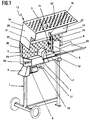
- This has a here designed as a mobile block machine frame 1 with an upper, arranged at a working height frame part in the form of a suitably formed by a hollow profile section longitudinal beam 2, which limits a receiving area 3 for a piece not shown here, to be split piece of wood down.
- the receiving area 3 is further limited by two in the direction perpendicular to the longitudinal direction of the longitudinal spar 2 upwardly upwardly directed stops 4, 5, one of which, here the stop 4, arranged stationary and provided with a splitting tool 6, here in the form of a riving knife, and of which the other stop, here the stopper 5, provided with a pressure plate 7 facing the splitting tool 6 and arranged movable in the longitudinal direction of the longitudinal spar 2 and by means of an associated drive means is displaceable.
- Said drive means includes an electric motor 8 for driving an adjacent hydraulic pump 9, through which a only in FIG. 2 partially visible, advantageously arranged within the longitudinal beam 2 hydraulic cylinder can be acted upon with pressure medium, which cooperates with the movable stop 5.
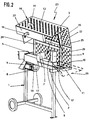
- FIG. 2 shows, which led out of the longitudinal beam 2 piston rod of the hydraulic cylinder 10 is provided with a yoke 11, which is connected via the longitudinal spar 2 flanking tie rods 12 with the movable stopper 5.
- FIG. 3 An operator operating the wood splitter shown is standing in the transverse direction of the longitudinal spar 2 next to the wood splitter.
- the in the representations according to Figures 1-3 the viewer facing side of the log splitter is therefore the operator facing the operator side.
- at least the operator side of the receiving area 3 is an in FIG. 3 assigned in function protective cover 13, which collects during the splitting operation in the direction of the operator thrown off wooden parts.
- the protective cover 13, in which it is in simple cases can be a simple protective shield, is attached to the machine frame 1, here on the receiving space 3 downwardly limiting frame part forming longitudinal beam 2 and contains, as shown in FIGS. 1 and 2 can be clearly seen, a raised and lowered arranged, here pivotally mounted flap 14 which is provided with a handle 15 for manual lifting and lowering.
- a switch is arranged, which is expediently actuated by means of the flap 14.
- the flap 14 has an actuating element 16 provided in the region of its lower edge, which, when the flap 14 is lowered, ie in the FIG. 3 underlying working position, comes to engage with said switch.
- This may conveniently be a micro-switch, which is protected and so removed from unauthorized operation in a mounted on the machine frame 1, suitably mounted on the longitudinal spar 2 box 17.
- This is provided with a microswitch accommodated therein micro slot 18 through which the microswitch is actuated by means of the flap side mounted actuator 16.
- the actuator 16 is provided for this purpose with respect to the pivot axis of the flap 14 tangentially in the closing direction of the flap 14 projecting tab 19 which retracts when closing the flap in the slot 18 and the microswitch located behind it operates as soon as the flap 14 is closed, ie in their lower end position is.
- the flap 14 By the operation of the flap 14 by means of the handle 15, a first operating hand is occupied.
- the second operating hand is assigned to another, manually operable Whyüngselement 20 remote from the handle 15, which serves to trigger an operation that must be triggered to effect a splitting process unconditionally.
- the control element 20 assigned to the second operating hand is a manually operable gearshift, suitably located in the region of the rear end side of the longitudinal spar 2 in the direction of displacement of the displaceable stop 5.
- a valve arranged in the pressure medium line leading from the pump 9 to the hydraulic cylinder 10 can be brought into a passage position and vice versa.
- the said valve can be designed so that with the aid of the operating element 20, for example by up or down pivoting a forward or backward movement of the stopper 5 can be initiated, and the valve is closed in a middle position of the operating element.
- the receiving area 3 associated protective cover 13 is formed as a housing, through which, as from Fig. 3 it can be seen that a receiving area 3 is formed during a cleaving process all around limiting chamber.
- Said housing has a rear wall 21 facing away from the operator side, at the upper edge remote from the longitudinal spar 2, the flap 14 adjoins a top wall 21 opposite the longitudinal spar 2 in the working position, to which a rear wall in FIG the working position opposite front wall 23 connects, to which the handle 15 and the actuator 16 are mounted.
- the chamber which is open to the enclosure, thus appears as a tunnel with an approximately rectangular cross-section.
- the above-outlined enclosure is practically designed as an additional unit, which can be optionally attached to the machine frame 1.
- angular support 24 are provided. It is expedient to provide a plurality of carriers 24 distributed over the length of the longitudinal spar 2. As a rule, two supports 24 arranged in the region of the ends of the longitudinal spar 2 are sufficient. These are designed and attached to the longitudinal spar 2 in such a way that the receiving space 3 give laterally flanking, standing leg, where the rear wall 21 may be attached and at the upper end of the flap 14 may be stored, as in the Figures 1-3 Is indicated by bearing pins or bearing bores 25.
- the flap 14 is as best as possible Fig. 2 can be seen, provided with the top wall 22 and front wall 23, the carriers 24 associated ribs 26, whose remote from the front wall 23 ends overlap with the longitudinal beam 2 remote from the ends of the attached thereto carrier 24 and are mounted thereon.
- mutually aligned bearing bores are provided, through which bearing pins are performed.
- the walls of the protective cover, at least the top wall 22 and the front wall 23 of the flap 14 are expediently made of a perforated plate so that perforations formed by the holes result, which allow observation of the splitting operation from the outside when the flap is closed.
- the rear wall 21 is formed as a perforated plate. The said perforations not only allow observation of the cleavage process from the outside, but also advantageously produce a desired weight saving, which facilitates the attachability of the protective cover according to the invention to the machine frame 1.
- the chamber bounded by the enclosure has a comparatively large, the width of the receiving area 3 downwardly limiting longitudinal beam 2 exceeding clear width.
- the rear wall 21 and the front wall 23 are therefore comparatively far away from the longitudinal spar 2 when the flap 14 is closed.
- the rear wall 21 and the front wall 23 in the region of their respective lower edge with striving strickenden, strip-shaped Wandabwinklept 27 are provided, the distance between the rear wall 21 and the longitudinal spar 2 and the flap closed and the distance between the front wall 23 and the Bridge longitudinal spar 2.
- the chamber formed by the enclosure is closed during the splitting operation also at the rear in the feed direction of the displaceable stop 5 end face by an associated end wall 28.
- the end wall 28 is suitably attached to the flap 14 in the example shown and formed as infill of the enclosed by the top wall 22 and the front wall 23 corner, which can cause a stiffening of the flap 14.
- the front end of the housing opposite the end wall 28 is open, so that the material to be split, i. the billets produced by the splitting process can be removed or ejected.
- the housing extends in the region of its open end beyond the stationary stop 4 provided with a splitting tool 6. This supernatant can expediently about half of the max. Length of a fissile piece of wood, i. about half of the stroke of the movable stop 5 correspond.
- the storage element 29 is, as best of Fig. 1 can be seen, above the tie rods 12 attached to the longitudinal spar 2. In Fig. 2 the storage element is indicated for simplicity of illustration only by broken lines.
- spring assembly 30 is provided which supports the lifting of the flap 14 and is tensioned when lowering the flap 14.
- the spring force of the spring assembly 30 acts through the weight of the flap 14 counteracted gravitational force, whereby the operation is facilitated and at the same time an automatic, full closing of the flap 14 counteracted.
- the spring assembly 30 is expediently dimensioned so that when lowering the flap 14 shortly before reaching its lower end position, the weight of the flap 14 is compensated by the spring force, so that the flap 14 can not close automatically, but that the complete closing of the flap 14th in addition to the weight of a further closing force is required, which must be applied by acting on the handle 15 operating hand. This ensures that the switch associated with the engine 8 is actuated only when the operator deliberately closes the flap 14 so that the engine 14 can not start involuntarily.
Landscapes
- Life Sciences & Earth Sciences (AREA)
- Engineering & Computer Science (AREA)
- Wood Science & Technology (AREA)
- Forests & Forestry (AREA)
- Mechanical Engineering (AREA)
- Debarking, Splitting, And Disintegration Of Timber (AREA)
Claims (9)
- Fendoir à bois, en particulier fendoir à bois horizontal pour fendre du bois, avec une zone de réception (3) prévue sur un bâti (1) pour recevoir un morceau de bois, qui est délimitée par une partie de bâti (2) et par des butées (4, 5) dépassant vers celle-ci perpendiculairement au sens de la longueur de la partie de bâti (2) et, d'une part, mobiles dans le sens de la longueur de la partie de bâti (2) et, d'autre part, stationnaires, une butée (4) contenant un outil de fendage (6) et la butée mobile (5) pouvant être entraînée au moyen d'un dispositif d'entraînement qui peut être activé au moyen d'un dispositif de commande nécessitant une commande à deux mains, de sorte qu'est associé au moins au côté de commande de la zone de réception (3) un capot de protection (13) disposé sur le bâti (1), qui comporte un volet (14) disposé de façon à pouvoir être relevé et abaissé et associé à une poignée (15) associée à une première main de l'opérateur, caractérisé en ce qu'est disposé dans la partie inférieure du bord inférieur du volet (14) un élément d'actionnement (16) qui se met en prise, quand le volet (14) est abaissé, avec un contacteur disposé du côté du bâti, qui est disposé dans l'alimentation électrique d'un moteur électrique pouvant entraîner une pompe associée à un vérin hydraulique associé à la butée mobile (5), à laquelle est associée une vanne qui peut être commandée au moyen d'un levier manuel formant un élément de commande (20) distant de la poignée (15) du volet (14) et associé à une deuxième main de l'opérateur.
- Fendoir à bois selon la revendication 1, caractérisé en ce que le capot de protection (15) est au moins en partie perforé et se compose de préférence d'une tôle perforée.
- Fendoir à bois selon l'une des revendications précédentes, caractérisé en ce que le capot de protection (13) est conformé comme un logement qui comprend une paroi arrière (21) disposée de préférence sur la partie de bâti (2) associée à la zone de réception (3) et le volet (14) qui est supporté de façon pivotante au niveau du bord de la paroi arrière (21) éloigné du bâti, et une paroi supérieure (22) qui fait face à la partie de bâti (2) et se raccorde à la paroi arrière (21) ainsi qu'une paroi avant qui s'y raccorde et qui fait face à la paroi arrière (21) et sur laquelle sont disposés la poignée (15) et l'élément d'actionnement (16).
- Fendoir à bois selon la revendication 3, caractérisé en ce que la paroi arrière (21) et la paroi avant (23) sont munies de bords repliés (27) se faisant face qui couvrent la distance qui les sépare de la partie de bâti (2).
- Fendoir à bois selon la revendication 3 ou 4, caractérisé en ce que le logement formant le capot de protection (13) peut être fermé au niveau de son extrémité distante de la butée stationnaire (5) par une paroi d'extrémité disposée de préférence sur le volet (14) et est ouvert à son extrémité opposée, qui dépasse au-delà de la butée stationnaire (4) munie d'un outil de fendage (6).
- Fendoir à bois selon l'une des revendications 3 à 5, caractérisé en ce que la butée stationnaire (4) munie d'un outil de fendage (6) est associée à un élément de dépose (29) dépassant du logement à l'extrémité ouverte de celui-ci.
- Fendoir à bois horizontal selon l'une des revendications précédentes, caractérisé en ce que le capot de protection (13) est associé à des supports (24) qui dépassent du côté du bâti (1), de préférence de la partie de bâti (2) associée à la zone de réception (3), opposé au côté de l'opérateur, qui peuvent être posés dessus et dont l'extrémité distante du bâti porte des paliers (25) associés au volet (14), et en ce que le volet (14) est muni de préférence de nervures (26) correspondant aux supports (24) qui reposent sur les supports (24) correspondants à leur extrémité tournée vers l'extrémité des supports (24) correspondants éloignée de la partie de bâti.
- Dispositif selon l'une des revendications précédentes, caractérisé en ce que le volet (14) est associé à une disposition de ressort (30) facilitant son mouvement d'ouverture, qui est dimensionnée de telle façon qu'une force de fermeture supplémentaire est nécessaire en plus du poids du volet (14) pour fermer celui-ci.
- Fendoir à bois selon l'une des revendications précédentes, caractérisé en ce que le contacteur pouvant être actionné au moyen du volet (14) est conformé comme un micro-contacteur disposé dans un boîtier (17) disposé sur le bâti (1) et en ce que l'élément d'actionnement (16) disposé sur le volet (14) présente une patte (19) qui dépasse de façon tangente par rapport à l'axe de pivotement du volet (14) et qui peut être insérée dans le boîtier (17) associé au micro-contacteur à travers une fente (18) du boîtier et mise en prise avec le micro-contacteur.
Priority Applications (1)
| Application Number | Priority Date | Filing Date | Title |
|---|---|---|---|
| SI201530332T SI3012076T1 (sl) | 2014-10-23 | 2015-09-09 | Cepilnik lesa |
Applications Claiming Priority (1)
| Application Number | Priority Date | Filing Date | Title |
|---|---|---|---|
| DE201420008426 DE202014008426U1 (de) | 2014-10-23 | 2014-10-23 | Holzspalter |
Publications (2)
| Publication Number | Publication Date |
|---|---|
| EP3012076A1 EP3012076A1 (fr) | 2016-04-27 |
| EP3012076B1 true EP3012076B1 (fr) | 2018-04-25 |
Family
ID=52017702
Family Applications (1)
| Application Number | Title | Priority Date | Filing Date |
|---|---|---|---|
| EP15002629.2A Not-in-force EP3012076B1 (fr) | 2014-10-23 | 2015-09-09 | Fendeuse |
Country Status (4)
| Country | Link |
|---|---|
| EP (1) | EP3012076B1 (fr) |
| DE (1) | DE202014008426U1 (fr) |
| DK (1) | DK3012076T3 (fr) |
| SI (1) | SI3012076T1 (fr) |
Families Citing this family (3)
| Publication number | Priority date | Publication date | Assignee | Title |
|---|---|---|---|---|
| EP3056327B1 (fr) * | 2015-02-10 | 2017-12-20 | Laitilan Rautarakenne Oy | Processeur de bois de chauffage |
| CA2920213C (fr) | 2015-02-10 | 2023-09-26 | Laitilan Rautarakenne Oy | Appareils de traitement de bois d'allumage |
| EP3569375B1 (fr) | 2018-05-18 | 2021-01-20 | Scheppach Fabrikation von Holzbearbeitungsmaschinen GmbH | Carter de protection pour fendeur de bois horizontal |
Citations (1)
| Publication number | Priority date | Publication date | Assignee | Title |
|---|---|---|---|---|
| EP0806271A2 (fr) * | 1996-05-08 | 1997-11-12 | Bell S.R.L. | Mécanisme de commande hydraulique pour fendeuses à bois |
Family Cites Families (13)
| Publication number | Priority date | Publication date | Assignee | Title |
|---|---|---|---|---|
| DE8914733U1 (de) * | 1989-12-15 | 1990-02-01 | Ziegler, Martin, Dipl.-Betriebsw. (FH), 8897 Pöttmes | Holzspalter Sicherheitsvorrichtung |
| DE8914734U1 (de) * | 1989-12-15 | 1990-02-01 | Ziegler, Martin, Dipl.-Betriebsw. (FH), 8897 Pöttmes | Holzspalter Sicherheitsvorrichtung |
| DE9010008U1 (de) * | 1990-07-03 | 1990-09-06 | Clauss Maschinenbau GmbH & Co, 7340 Geislingen | Hydraulisch angetriebene Keilspaltmaschine (Holzspalter) für Brennholz |
| DE9112911U1 (de) * | 1991-05-07 | 1992-01-30 | Kretzer, Walter, 7951 Eberhardzell | Holzspaltvorrichtung mit hydraulisch betätigbarem Stempel |
| DE4115838A1 (de) * | 1991-05-15 | 1992-11-19 | Steigerwald Rudolf Dipl Ing Fh | Holzspaltmaschine mit sicherheitsschaltung, beweglichen schutzverkleidungen und zufuehr- und entnahmevorrichtungen |
| DE9216169U1 (de) * | 1992-11-27 | 1993-04-08 | Hydraulik Markranstädt GmbH, O-7153 Markranstädt | Holzspaltgerät |
| DE29713109U1 (de) * | 1997-07-23 | 1997-11-27 | Vodermair, Bert, 83254 Breitbrunn | Hydraulischer Brennholzspalter in Modulbauweise mit Schutzhaube und Sicherheitssteuerung |
| DE102006032054A1 (de) | 2006-03-24 | 2008-01-17 | Scheppach Fabrikation Von Holzbearbeitungsmaschinen Gmbh | Stehend-Holzspalter |
| DE202010017203U1 (de) * | 2009-07-31 | 2011-04-28 | Biberger, Konrad | Holzspalter |
| AT509373B1 (de) * | 2010-02-05 | 2011-12-15 | Hechenblaickner Helmut | Holzspalter |
| US20120255650A1 (en) * | 2011-04-06 | 2012-10-11 | Efab Llc | Log splitter apparatus and related methods |
| DE202011005576U1 (de) * | 2011-04-21 | 2011-10-17 | Kaspar Pauli Gmbh | Holzspalter |
| DE202011107748U1 (de) * | 2011-11-12 | 2013-02-14 | Johann Kernstock | Vorrichtung zum Spalten von Holzstücken |
-
2014
- 2014-10-23 DE DE201420008426 patent/DE202014008426U1/de not_active Expired - Lifetime
-
2015
- 2015-09-09 SI SI201530332T patent/SI3012076T1/sl unknown
- 2015-09-09 EP EP15002629.2A patent/EP3012076B1/fr not_active Not-in-force
- 2015-09-09 DK DK15002629.2T patent/DK3012076T3/en active
Patent Citations (1)
| Publication number | Priority date | Publication date | Assignee | Title |
|---|---|---|---|---|
| EP0806271A2 (fr) * | 1996-05-08 | 1997-11-12 | Bell S.R.L. | Mécanisme de commande hydraulique pour fendeuses à bois |
Also Published As
| Publication number | Publication date |
|---|---|
| EP3012076A1 (fr) | 2016-04-27 |
| DE202014008426U1 (de) | 2014-11-25 |
| DK3012076T3 (en) | 2018-08-06 |
| SI3012076T1 (sl) | 2018-09-28 |
Similar Documents
| Publication | Publication Date | Title |
|---|---|---|
| DE2851320C2 (de) | Schneid- bzw. Abbrucheinrichtung zum Abbrechen von bewehrten Betonwänden od.dgl. | |
| EP1992461B1 (fr) | Dispositif de scie à bascule | |
| EP2279838A2 (fr) | Fendeur de bois | |
| DE2444459A1 (de) | Einrichtung zum schutz gegen raubueberfaelle | |
| WO1993019001A1 (fr) | Dispositif de retenue pour balles | |
| EP3012076A1 (fr) | Fendeuse | |
| DE1432562C3 (de) | Maschine zum Zartmachen von Fleisch | |
| EP2386391B1 (fr) | Fendeur de bois doté d'une surface de transport et d'une surface de stabilisation se déroulant dans l'intervalle de fente pour fendre des bûches de bois à partir d'un tronc | |
| CH687237A5 (de) | Zerkleinerungsvorrichtung. | |
| EP2202376B1 (fr) | Système de porte coulissante et basculante | |
| EP2390071B1 (fr) | Scie circulaire à bascule | |
| DE3909082A1 (de) | Tuerschloss | |
| DE112014006266B4 (de) | Gartenscheren mit Schnitt-Umschaltmodus | |
| EP1325995A2 (fr) | Dispositif de sécurité interdisant l'ouverture simultanée, notamment pour armoires à tiroirs | |
| DE202009005212U1 (de) | Holzspalter | |
| DE2727817C3 (de) | Schneideinrichtung, insbesondere Stapelschneider | |
| EP3569375B1 (fr) | Carter de protection pour fendeur de bois horizontal | |
| DE9112911U1 (de) | Holzspaltvorrichtung mit hydraulisch betätigbarem Stempel | |
| AT12006U1 (de) | Holzspalter mit schutzbügelanordnung | |
| AT11020U1 (de) | Holzspalter | |
| DE10346909A1 (de) | Spargelerntegerät | |
| DE3536141C2 (de) | Vorrichtung zum Schneiden von Silagegut | |
| DE102013113117A1 (de) | Hubvorrichtung für das Dach eines Nutzfahrzeugaufbaus | |
| DE2800353A1 (de) | Schneidvorrichtung fuer selbstladewagen | |
| DE2329127B2 (de) | Artikelaufbewahrungsanlage mit paternosterartig in Umlauf versetzbaren Trägern |
Legal Events
| Date | Code | Title | Description |
|---|---|---|---|
| PUAI | Public reference made under article 153(3) epc to a published international application that has entered the european phase |
Free format text: ORIGINAL CODE: 0009012 |
|
| AK | Designated contracting states |
Kind code of ref document: A1 Designated state(s): AL AT BE BG CH CY CZ DE DK EE ES FI FR GB GR HR HU IE IS IT LI LT LU LV MC MK MT NL NO PL PT RO RS SE SI SK SM TR |
|
| AX | Request for extension of the european patent |
Extension state: BA ME |
|
| 17P | Request for examination filed |
Effective date: 20160715 |
|
| RBV | Designated contracting states (corrected) |
Designated state(s): AL AT BE BG CH CY CZ DE DK EE ES FI FR GB GR HR HU IE IS IT LI LT LU LV MC MK MT NL NO PL PT RO RS SE SI SK SM TR |
|
| 17Q | First examination report despatched |
Effective date: 20170801 |
|
| GRAP | Despatch of communication of intention to grant a patent |
Free format text: ORIGINAL CODE: EPIDOSNIGR1 |
|
| INTG | Intention to grant announced |
Effective date: 20180202 |
|
| GRAA | (expected) grant |
Free format text: ORIGINAL CODE: 0009210 |
|
| GRAS | Grant fee paid |
Free format text: ORIGINAL CODE: EPIDOSNIGR3 |
|
| AK | Designated contracting states |
Kind code of ref document: B1 Designated state(s): AL AT BE BG CH CY CZ DE DK EE ES FI FR GB GR HR HU IE IS IT LI LT LU LV MC MK MT NL NO PL PT RO RS SE SI SK SM TR |
|
| REG | Reference to a national code |
Ref country code: GB Ref legal event code: FG4D Free format text: NOT ENGLISH |
|
| REG | Reference to a national code |
Ref country code: CH Ref legal event code: EP |
|
| REG | Reference to a national code |
Ref country code: AT Ref legal event code: REF Ref document number: 992386 Country of ref document: AT Kind code of ref document: T Effective date: 20180515 |
|
| REG | Reference to a national code |
Ref country code: IE Ref legal event code: FG4D Free format text: LANGUAGE OF EP DOCUMENT: GERMAN |
|
| REG | Reference to a national code |
Ref country code: DE Ref legal event code: R096 Ref document number: 502015003970 Country of ref document: DE |
|
| REG | Reference to a national code |
Ref country code: CH Ref legal event code: NV Representative=s name: PATENTANWAELTE MUNK, DE |
|
| REG | Reference to a national code |
Ref country code: DK Ref legal event code: T3 Effective date: 20180730 |
|
| REG | Reference to a national code |
Ref country code: SE Ref legal event code: TRGR |
|
| REG | Reference to a national code |
Ref country code: NL Ref legal event code: MP Effective date: 20180425 |
|
| REG | Reference to a national code |
Ref country code: LT Ref legal event code: MG4D |
|
| REG | Reference to a national code |
Ref country code: FR Ref legal event code: PLFP Year of fee payment: 4 |
|
| PG25 | Lapsed in a contracting state [announced via postgrant information from national office to epo] |
Ref country code: NL Free format text: LAPSE BECAUSE OF FAILURE TO SUBMIT A TRANSLATION OF THE DESCRIPTION OR TO PAY THE FEE WITHIN THE PRESCRIBED TIME-LIMIT Effective date: 20180425 |
|
| PG25 | Lapsed in a contracting state [announced via postgrant information from national office to epo] |
Ref country code: ES Free format text: LAPSE BECAUSE OF FAILURE TO SUBMIT A TRANSLATION OF THE DESCRIPTION OR TO PAY THE FEE WITHIN THE PRESCRIBED TIME-LIMIT Effective date: 20180425 Ref country code: LT Free format text: LAPSE BECAUSE OF FAILURE TO SUBMIT A TRANSLATION OF THE DESCRIPTION OR TO PAY THE FEE WITHIN THE PRESCRIBED TIME-LIMIT Effective date: 20180425 Ref country code: PL Free format text: LAPSE BECAUSE OF FAILURE TO SUBMIT A TRANSLATION OF THE DESCRIPTION OR TO PAY THE FEE WITHIN THE PRESCRIBED TIME-LIMIT Effective date: 20180425 Ref country code: NO Free format text: LAPSE BECAUSE OF FAILURE TO SUBMIT A TRANSLATION OF THE DESCRIPTION OR TO PAY THE FEE WITHIN THE PRESCRIBED TIME-LIMIT Effective date: 20180725 Ref country code: BG Free format text: LAPSE BECAUSE OF FAILURE TO SUBMIT A TRANSLATION OF THE DESCRIPTION OR TO PAY THE FEE WITHIN THE PRESCRIBED TIME-LIMIT Effective date: 20180725 |
|
| PG25 | Lapsed in a contracting state [announced via postgrant information from national office to epo] |
Ref country code: GR Free format text: LAPSE BECAUSE OF FAILURE TO SUBMIT A TRANSLATION OF THE DESCRIPTION OR TO PAY THE FEE WITHIN THE PRESCRIBED TIME-LIMIT Effective date: 20180726 Ref country code: RS Free format text: LAPSE BECAUSE OF FAILURE TO SUBMIT A TRANSLATION OF THE DESCRIPTION OR TO PAY THE FEE WITHIN THE PRESCRIBED TIME-LIMIT Effective date: 20180425 Ref country code: LV Free format text: LAPSE BECAUSE OF FAILURE TO SUBMIT A TRANSLATION OF THE DESCRIPTION OR TO PAY THE FEE WITHIN THE PRESCRIBED TIME-LIMIT Effective date: 20180425 Ref country code: HR Free format text: LAPSE BECAUSE OF FAILURE TO SUBMIT A TRANSLATION OF THE DESCRIPTION OR TO PAY THE FEE WITHIN THE PRESCRIBED TIME-LIMIT Effective date: 20180425 |
|
| PG25 | Lapsed in a contracting state [announced via postgrant information from national office to epo] |
Ref country code: PT Free format text: LAPSE BECAUSE OF FAILURE TO SUBMIT A TRANSLATION OF THE DESCRIPTION OR TO PAY THE FEE WITHIN THE PRESCRIBED TIME-LIMIT Effective date: 20180827 |
|
| REG | Reference to a national code |
Ref country code: DE Ref legal event code: R097 Ref document number: 502015003970 Country of ref document: DE |
|
| PG25 | Lapsed in a contracting state [announced via postgrant information from national office to epo] |
Ref country code: SK Free format text: LAPSE BECAUSE OF FAILURE TO SUBMIT A TRANSLATION OF THE DESCRIPTION OR TO PAY THE FEE WITHIN THE PRESCRIBED TIME-LIMIT Effective date: 20180425 Ref country code: EE Free format text: LAPSE BECAUSE OF FAILURE TO SUBMIT A TRANSLATION OF THE DESCRIPTION OR TO PAY THE FEE WITHIN THE PRESCRIBED TIME-LIMIT Effective date: 20180425 Ref country code: RO Free format text: LAPSE BECAUSE OF FAILURE TO SUBMIT A TRANSLATION OF THE DESCRIPTION OR TO PAY THE FEE WITHIN THE PRESCRIBED TIME-LIMIT Effective date: 20180425 |
|
| PG25 | Lapsed in a contracting state [announced via postgrant information from national office to epo] |
Ref country code: IT Free format text: LAPSE BECAUSE OF FAILURE TO SUBMIT A TRANSLATION OF THE DESCRIPTION OR TO PAY THE FEE WITHIN THE PRESCRIBED TIME-LIMIT Effective date: 20180425 Ref country code: SM Free format text: LAPSE BECAUSE OF FAILURE TO SUBMIT A TRANSLATION OF THE DESCRIPTION OR TO PAY THE FEE WITHIN THE PRESCRIBED TIME-LIMIT Effective date: 20180425 |
|
| PLBE | No opposition filed within time limit |
Free format text: ORIGINAL CODE: 0009261 |
|
| STAA | Information on the status of an ep patent application or granted ep patent |
Free format text: STATUS: NO OPPOSITION FILED WITHIN TIME LIMIT |
|
| 26N | No opposition filed |
Effective date: 20190128 |
|
| PG25 | Lapsed in a contracting state [announced via postgrant information from national office to epo] |
Ref country code: MC Free format text: LAPSE BECAUSE OF FAILURE TO SUBMIT A TRANSLATION OF THE DESCRIPTION OR TO PAY THE FEE WITHIN THE PRESCRIBED TIME-LIMIT Effective date: 20180425 |
|
| REG | Reference to a national code |
Ref country code: BE Ref legal event code: MM Effective date: 20180930 |
|
| REG | Reference to a national code |
Ref country code: IE Ref legal event code: MM4A |
|
| PG25 | Lapsed in a contracting state [announced via postgrant information from national office to epo] |
Ref country code: LU Free format text: LAPSE BECAUSE OF NON-PAYMENT OF DUE FEES Effective date: 20180909 |
|
| PG25 | Lapsed in a contracting state [announced via postgrant information from national office to epo] |
Ref country code: IE Free format text: LAPSE BECAUSE OF NON-PAYMENT OF DUE FEES Effective date: 20180909 |
|
| PG25 | Lapsed in a contracting state [announced via postgrant information from national office to epo] |
Ref country code: BE Free format text: LAPSE BECAUSE OF NON-PAYMENT OF DUE FEES Effective date: 20180930 |
|
| PG25 | Lapsed in a contracting state [announced via postgrant information from national office to epo] |
Ref country code: AL Free format text: LAPSE BECAUSE OF FAILURE TO SUBMIT A TRANSLATION OF THE DESCRIPTION OR TO PAY THE FEE WITHIN THE PRESCRIBED TIME-LIMIT Effective date: 20180425 |
|
| PG25 | Lapsed in a contracting state [announced via postgrant information from national office to epo] |
Ref country code: MT Free format text: LAPSE BECAUSE OF FAILURE TO SUBMIT A TRANSLATION OF THE DESCRIPTION OR TO PAY THE FEE WITHIN THE PRESCRIBED TIME-LIMIT Effective date: 20180425 |
|
| PG25 | Lapsed in a contracting state [announced via postgrant information from national office to epo] |
Ref country code: TR Free format text: LAPSE BECAUSE OF FAILURE TO SUBMIT A TRANSLATION OF THE DESCRIPTION OR TO PAY THE FEE WITHIN THE PRESCRIBED TIME-LIMIT Effective date: 20180425 |
|
| PG25 | Lapsed in a contracting state [announced via postgrant information from national office to epo] |
Ref country code: MK Free format text: LAPSE BECAUSE OF NON-PAYMENT OF DUE FEES Effective date: 20180425 Ref country code: HU Free format text: LAPSE BECAUSE OF FAILURE TO SUBMIT A TRANSLATION OF THE DESCRIPTION OR TO PAY THE FEE WITHIN THE PRESCRIBED TIME-LIMIT; INVALID AB INITIO Effective date: 20150909 Ref country code: CY Free format text: LAPSE BECAUSE OF FAILURE TO SUBMIT A TRANSLATION OF THE DESCRIPTION OR TO PAY THE FEE WITHIN THE PRESCRIBED TIME-LIMIT Effective date: 20180425 |
|
| PG25 | Lapsed in a contracting state [announced via postgrant information from national office to epo] |
Ref country code: IS Free format text: LAPSE BECAUSE OF FAILURE TO SUBMIT A TRANSLATION OF THE DESCRIPTION OR TO PAY THE FEE WITHIN THE PRESCRIBED TIME-LIMIT Effective date: 20180825 |
|
| PGFP | Annual fee paid to national office [announced via postgrant information from national office to epo] |
Ref country code: FR Payment date: 20210927 Year of fee payment: 7 Ref country code: CZ Payment date: 20210830 Year of fee payment: 7 Ref country code: CH Payment date: 20210923 Year of fee payment: 7 Ref country code: FI Payment date: 20210920 Year of fee payment: 7 Ref country code: AT Payment date: 20210917 Year of fee payment: 7 |
|
| PGFP | Annual fee paid to national office [announced via postgrant information from national office to epo] |
Ref country code: GB Payment date: 20210923 Year of fee payment: 7 Ref country code: SI Payment date: 20210831 Year of fee payment: 7 Ref country code: SE Payment date: 20210921 Year of fee payment: 7 Ref country code: DE Payment date: 20210930 Year of fee payment: 7 Ref country code: DK Payment date: 20210921 Year of fee payment: 7 |
|
| REG | Reference to a national code |
Ref country code: DE Ref legal event code: R119 Ref document number: 502015003970 Country of ref document: DE |
|
| PG25 | Lapsed in a contracting state [announced via postgrant information from national office to epo] |
Ref country code: FI Free format text: LAPSE BECAUSE OF NON-PAYMENT OF DUE FEES Effective date: 20220909 Ref country code: CZ Free format text: LAPSE BECAUSE OF NON-PAYMENT OF DUE FEES Effective date: 20220909 |
|
| REG | Reference to a national code |
Ref country code: CH Ref legal event code: PL |
|
| REG | Reference to a national code |
Ref country code: DK Ref legal event code: EBP Effective date: 20220930 |
|
| REG | Reference to a national code |
Ref country code: SE Ref legal event code: EUG |
|
| REG | Reference to a national code |
Ref country code: AT Ref legal event code: MM01 Ref document number: 992386 Country of ref document: AT Kind code of ref document: T Effective date: 20220909 |
|
| GBPC | Gb: european patent ceased through non-payment of renewal fee |
Effective date: 20220909 |
|
| REG | Reference to a national code |
Ref country code: SI Ref legal event code: KO00 Effective date: 20230518 |
|
| PG25 | Lapsed in a contracting state [announced via postgrant information from national office to epo] |
Ref country code: LI Free format text: LAPSE BECAUSE OF NON-PAYMENT OF DUE FEES Effective date: 20220930 Ref country code: FR Free format text: LAPSE BECAUSE OF NON-PAYMENT OF DUE FEES Effective date: 20220930 Ref country code: DE Free format text: LAPSE BECAUSE OF NON-PAYMENT OF DUE FEES Effective date: 20230401 Ref country code: CH Free format text: LAPSE BECAUSE OF NON-PAYMENT OF DUE FEES Effective date: 20220930 Ref country code: AT Free format text: LAPSE BECAUSE OF NON-PAYMENT OF DUE FEES Effective date: 20220909 |
|
| PG25 | Lapsed in a contracting state [announced via postgrant information from national office to epo] |
Ref country code: SI Free format text: LAPSE BECAUSE OF NON-PAYMENT OF DUE FEES Effective date: 20220910 Ref country code: SE Free format text: LAPSE BECAUSE OF NON-PAYMENT OF DUE FEES Effective date: 20220910 |
|
| PG25 | Lapsed in a contracting state [announced via postgrant information from national office to epo] |
Ref country code: GB Free format text: LAPSE BECAUSE OF NON-PAYMENT OF DUE FEES Effective date: 20220909 Ref country code: DK Free format text: LAPSE BECAUSE OF NON-PAYMENT OF DUE FEES Effective date: 20220930 |