EP3012124B1 - Achsenanordnung für ein reifenfüllsystem - Google Patents
Achsenanordnung für ein reifenfüllsystem Download PDFInfo
- Publication number
- EP3012124B1 EP3012124B1 EP15187539.0A EP15187539A EP3012124B1 EP 3012124 B1 EP3012124 B1 EP 3012124B1 EP 15187539 A EP15187539 A EP 15187539A EP 3012124 B1 EP3012124 B1 EP 3012124B1
- Authority
- EP
- European Patent Office
- Prior art keywords
- pilot
- axle
- supply
- conduit
- bore
- Prior art date
- Legal status (The legal status is an assumption and is not a legal conclusion. Google has not performed a legal analysis and makes no representation as to the accuracy of the status listed.)
- Active
Links
Images


Classifications
-
- B—PERFORMING OPERATIONS; TRANSPORTING
- B60—VEHICLES IN GENERAL
- B60C—VEHICLE TYRES; TYRE INFLATION; TYRE CHANGING; CONNECTING VALVES TO INFLATABLE ELASTIC BODIES IN GENERAL; DEVICES OR ARRANGEMENTS RELATED TO TYRES
- B60C23/00—Devices for measuring, signalling, controlling, or distributing tyre pressure or temperature, specially adapted for mounting on vehicles; Arrangement of tyre inflating devices on vehicles, e.g. of pumps or of tanks; Tyre cooling arrangements
- B60C23/001—Devices for manually or automatically controlling or distributing tyre pressure whilst the vehicle is moving
- B60C23/003—Devices for manually or automatically controlling or distributing tyre pressure whilst the vehicle is moving comprising rotational joints between vehicle-mounted pressure sources and the tyres
- B60C23/00372—Devices for manually or automatically controlling or distributing tyre pressure whilst the vehicle is moving comprising rotational joints between vehicle-mounted pressure sources and the tyres characterised by fluid diagrams
-
- B—PERFORMING OPERATIONS; TRANSPORTING
- B60—VEHICLES IN GENERAL
- B60C—VEHICLE TYRES; TYRE INFLATION; TYRE CHANGING; CONNECTING VALVES TO INFLATABLE ELASTIC BODIES IN GENERAL; DEVICES OR ARRANGEMENTS RELATED TO TYRES
- B60C23/00—Devices for measuring, signalling, controlling, or distributing tyre pressure or temperature, specially adapted for mounting on vehicles; Arrangement of tyre inflating devices on vehicles, e.g. of pumps or of tanks; Tyre cooling arrangements
- B60C23/001—Devices for manually or automatically controlling or distributing tyre pressure whilst the vehicle is moving
- B60C23/003—Devices for manually or automatically controlling or distributing tyre pressure whilst the vehicle is moving comprising rotational joints between vehicle-mounted pressure sources and the tyres
- B60C23/00309—Devices for manually or automatically controlling or distributing tyre pressure whilst the vehicle is moving comprising rotational joints between vehicle-mounted pressure sources and the tyres characterised by the location of the components, e.g. valves, sealings, conduits or sensors
- B60C23/00318—Devices for manually or automatically controlling or distributing tyre pressure whilst the vehicle is moving comprising rotational joints between vehicle-mounted pressure sources and the tyres characterised by the location of the components, e.g. valves, sealings, conduits or sensors on the wheels or the hubs
-
- B—PERFORMING OPERATIONS; TRANSPORTING
- B60—VEHICLES IN GENERAL
- B60C—VEHICLE TYRES; TYRE INFLATION; TYRE CHANGING; CONNECTING VALVES TO INFLATABLE ELASTIC BODIES IN GENERAL; DEVICES OR ARRANGEMENTS RELATED TO TYRES
- B60C23/00—Devices for measuring, signalling, controlling, or distributing tyre pressure or temperature, specially adapted for mounting on vehicles; Arrangement of tyre inflating devices on vehicles, e.g. of pumps or of tanks; Tyre cooling arrangements
- B60C23/001—Devices for manually or automatically controlling or distributing tyre pressure whilst the vehicle is moving
- B60C23/003—Devices for manually or automatically controlling or distributing tyre pressure whilst the vehicle is moving comprising rotational joints between vehicle-mounted pressure sources and the tyres
- B60C23/00309—Devices for manually or automatically controlling or distributing tyre pressure whilst the vehicle is moving comprising rotational joints between vehicle-mounted pressure sources and the tyres characterised by the location of the components, e.g. valves, sealings, conduits or sensors
- B60C23/00336—Devices for manually or automatically controlling or distributing tyre pressure whilst the vehicle is moving comprising rotational joints between vehicle-mounted pressure sources and the tyres characterised by the location of the components, e.g. valves, sealings, conduits or sensors on the axles
-
- B—PERFORMING OPERATIONS; TRANSPORTING
- B60—VEHICLES IN GENERAL
- B60C—VEHICLE TYRES; TYRE INFLATION; TYRE CHANGING; CONNECTING VALVES TO INFLATABLE ELASTIC BODIES IN GENERAL; DEVICES OR ARRANGEMENTS RELATED TO TYRES
- B60C23/00—Devices for measuring, signalling, controlling, or distributing tyre pressure or temperature, specially adapted for mounting on vehicles; Arrangement of tyre inflating devices on vehicles, e.g. of pumps or of tanks; Tyre cooling arrangements
- B60C23/001—Devices for manually or automatically controlling or distributing tyre pressure whilst the vehicle is moving
- B60C23/003—Devices for manually or automatically controlling or distributing tyre pressure whilst the vehicle is moving comprising rotational joints between vehicle-mounted pressure sources and the tyres
- B60C23/00354—Details of valves
-
- B—PERFORMING OPERATIONS; TRANSPORTING
- B60—VEHICLES IN GENERAL
- B60C—VEHICLE TYRES; TYRE INFLATION; TYRE CHANGING; CONNECTING VALVES TO INFLATABLE ELASTIC BODIES IN GENERAL; DEVICES OR ARRANGEMENTS RELATED TO TYRES
- B60C23/00—Devices for measuring, signalling, controlling, or distributing tyre pressure or temperature, specially adapted for mounting on vehicles; Arrangement of tyre inflating devices on vehicles, e.g. of pumps or of tanks; Tyre cooling arrangements
- B60C23/001—Devices for manually or automatically controlling or distributing tyre pressure whilst the vehicle is moving
- B60C23/003—Devices for manually or automatically controlling or distributing tyre pressure whilst the vehicle is moving comprising rotational joints between vehicle-mounted pressure sources and the tyres
- B60C23/00363—Details of sealings
Definitions
- the present invention relates to an axle assembly for a tire inflation system.
- Central tire inflation systems especially in agricultural applications have been designed to adjust tire inflation so that tires will have better performance during different situations, such as during transport duty and during operation in the field.
- systems for regulating tire pressure can reduce tire pressure during field operation in contrast to the higher pressure used during on-road operation.
- Certain vehicles, such as agricultural tractors have rack and pinion "bar" type axles so that the wheels and tires can be placed at different positions on the axle. This allows the tread width of the vehicle to adapted to different situations. It is desired to provide an axle assembly which works with a tire inflation system on a vehicle which has an adjustable tread width.
- US 6 435 238 B1 shows a stationary axle with air conduits and ABS cables routed through the interior of the non-rotating axle.
- US 1 794 900 A , US 4 387 931 A , US 6 435 238 B1 and US 6 145 559 A show designs where tire pressure passages pass through a vehicle axle. However, none of these designs provide for both a supply pressure and a pilot pressure for a tire inflation control valve. And, none of these designs can accommodate a wheel and tire which can be placed at different positions on the axle.
- US5,253,688 discloses an axle assembly for a tire inflation system, the axle assembly having a pilot operated wheel control valve for controlling tire pressure as a function of a pilot pressure, the axle assembly supporting a wheel hub which is adjustable in a plurality of positions; an axle housing and an axle rotatably supported by the axle housing; a flexible supply air hose connected to the supply outlet and a flexible pilot air hose connected to the pilot outlet.
- WO2013/056988 A1 discloses a supply passage extending axially along a central axis of an axle from a first passage end to a second passage end and a pilot conduit extending through the supply passage.
- an axle assembly for a tire inflation system comprises a pilot operated wheel control valve for controlling tire pressure as a function of a pilot pressure.
- the axle assembly supports a wheel hub which is adjustable in a plurality of positions.
- the axle assembly further comprises an axle housing and an axle which is rotatably supported by the axle housing.
- a supply passage extends axially along a central axis of the axle from a first passage end to a second passage end.
- a pilot conduit extends through the supply passage and extends from a first conduit end to a second conduit end.
- a supply inlet is provided for communicating a source of supply pressure with the first passage end of the supply passage.
- a supply outlet communicates the second passage end of the supply passage with the pilot operated wheel control valve.
- a pilot inlet is provided for communicating a source of pilot pressure with the first conduit end of the pilot conduit.
- a pilot outlet communicates the second conduit end of the pilot conduit with the pilot operated wheel control valve.
- a flexible supply air hose is connected to the supply outlet.
- a flexible pilot air hose is connected to the pilot outlet, wherein the supply and pilot hoses are coiled around an outer surface of the axle.
- a tire inflation system 10 includes an air compressor 12 and an atmospheric vent 14.
- the air compressor 12 draws air from a filter 16 and may push the air through a dryer 18 to an inlet of a solenoid operated inflation/deflation control valve 20.
- a line 22 between dryer 18 and control valve 20 is connected to a vent 28 by line 23, a pressure relief valve 24 and a check valve 26.
- a supply line 30 communicates a supply outlet 32 of inflation/deflation control valve 20 to an axle assembly 34 which is part of the tire inflation system 10.
- An exhaust line 36 communicates port 38 of inflation/deflation control valve 20 through a check valve 40 to the atmospheric vent 14.
- Line 42 communicates port 44 of inflation/deflation control valve 20 to port 48 of wheel pressure control valve 46.
- Port 50 of wheel pressure control valve 46 is communicated to a vent 52.
- Line 53 communicates port 54 of wheel pressure control valve 46 to the axle assembly 34.
- Line 60 communicates axle assembly 34 to a supply port 64 of pilot operated wheel control valve 62.
- Line 66 communicates axle assembly 34 to a pilot port 68 of pilot operated wheel control valve 62.
- Line 72 communicates outlet 70 of pilot operated wheel control valve 62 to a tire 74 which is mounted on a wheel hub 76.
- the above description applies to a tire inflation system 10 for a single tire 74.
- the tire inflation system 10 could be also applied to additional tires (not shown) by adding additional control valves such as control valves 46 and 62 for each tire.
- the axle assembly 34 includes an axle housing 82 and an axle 84.
- An inboard end 86 of axle 84 is received by and rotatably supported by the axle housing 82.
- An outboard portion 88 of axle 84 supports the wheel hub 76 and includes a conventional rack 90 which is used to adjust the position of the wheel hub 76 in a known manner.
- a central axial supply bore 100 is formed in the axle 84 and extends from an end wall 102 to an axially outer end 104 of the axle 84.
- a radial supply passage 106 extends though the axle 84 and communicates a first end of central axial supply bore 100 to the exterior of the axle 84.
- a radial supply passage 108 extends through the axle housing 82 and communicates radial supply passage 106 to the exterior of the axle housing 82 and with exhaust line 30.
- An end plate 110 is sealingly attached to and covers the axially outer end 104 of the axle 84.
- a radial passage 112 extends through the end plate 110 and communicates the outer end of central axial supply bore 100 with a supply outlet 114 and with line 60.
- a central axial pilot bore 116 opens toward the axle 84 and extends part way into the end plate 110.
- Central axial pilot bore 116 receives and supports the outer end of pilot conduit 118.
- a radial passage 120 extends through the end plate 110 and communicates central axial pilot bore 116 with a pilot outlet 122 and with line 66.
- a flexible supply air hose 92 is coiled around the axle 84 and connects supply outlet 114 with a manifold 94 and line 60.
- a flexible pilot air hose 96 is coiled around the axle 84 and connects pilot outlet 122 with manifold 94 and line 66.
- the air hoses 92 and 96 are coiled around a portion of the axle 84 between the end plate 110 and the wheel hub 76.
- the air hoses 92 and 96 flex to maintain a connection between lines 30 and 53 and the pilot operated wheel control valve 62 as the wheel hub 76 is moved axially to different positions on the axle 84.
- Pilot conduit 118 extends through the entire length of central axial supply bore 100, is coaxial with central axial supply bore 100, and has a smaller diameter than the diameter of central axial supply bore 100.
- the larger diameter central axial supply bore 100 and the smaller diameter central axial pilot bore 116 have a common axis.
- the axle housing 82 surrounds the inner portion 86 of the axle 84, surrounds an inner end of the central axial supply bore 100, and surrounds an inner end 119 of the pilot conduit 118.
- the central axial supply bore 100 and the pilot conduit 118 are both coaxial with a central rotation axis of the axle 84 and are symmetrical with respect to that axis.
- a central axial pilot bore 126 extends into the axle 84 axially inwardly from end wall 102.
- Central axial pilot bore 126 is a blind bore, and has a diameter which is smaller than the diameter of central axial supply bore 100.
- Central axial pilot bore 126 receives and supports an inner end of pilot conduit 118, and communicates the interior of pilot conduit 118 with a radial pilot passage 128.
- Central axial pilot bore 126 has a stepped diameter which forms an annular shoulder 127 which engages an end of the pilot conduit 118.
- Radial pilot passage 128 extends radially through the axle 84 and communicates central axial pilot bore 126 with the outer surface of the axle 84.
- a radial supply passage 130 extends through the axle housing 82 and communicates radial pilot passage 128 to the exterior of the axle housing 82 and to line 53. Seals 129 seal the radial supply and pilot passages 130 and 128 from each other and from the environment.
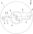
- a circular cover plate 132 covers the end plate 110.
- the end plate 110 includes a central hub 140 and a pair of arms 142 and 144 which project radially outwardly from the central hub 140 to clear the wheel hub 76.
- Bolts 134 and 136 extend through cover plate 132 and through end plate 110 and are threadably received by threaded bores (not shown) in the axially outer end 104 of axle 84.
- axle assembly 34 which communicates a controlled supply of pressurized air to a tire 74 which can be placed at different positions on the axle 84.
- the air passages formed by central axial supply bore 100 and pilot conduit 118 are routed through axle housing 82 which protects the air passages from external damage.
- the tread width can be changed without disturbing the tire inflation system 10.
- the central axial supply passage 100 has a larger diameter than the pilot conduit 118 so that tire 74 can be rapidly inflated or deflated.
Landscapes
- Engineering & Computer Science (AREA)
- Mechanical Engineering (AREA)
- Tires In General (AREA)
Claims (7)
- Achsanordnung für ein Reifenaufblassystem, wobei die Achsanordnung (34) ein vorgesteuertes Radsteuerventil (62) zum Steuern des Reifendrucks in Abhängigkeit von einem Vorsteuerdruck, wobei die Achsanordnung (34) eine Radnabe (76) stützt, die in mehrere Stellungen einstellbar ist; ein Achsgehäuse (82); eine Achse (84), die durch das Achsgehäuse (82) drehbar gestützt wird; einen Zufuhrkanal (100), der sich axial entlang einer Mittelachse der Achse (84) von einem ersten Kanalende zu einem zweiten Kanalende (104) erstreckt; eine Vorsteuerleitung (118), die sich durch den Zufuhrkanal (100) erstreckt und sich von einem ersten Leitungsende (119) zu einem zweiten Leitungsende erstreckt; einen Zufuhreinlass (108) zur Verbindung einer Zufuhrdruckquelle (12) mit dem ersten Kanalende des Zufuhrkanals (100); einen Zufuhrauslass (114), der das zweite Kanalende (104) des Zufuhrkanals (100) mit dem vorgesteuerten Radsteuerventil (62) verbindet; einen Vorsteuereinlass (128) zur Verbindung einer Vorsteuerdruckquelle (46) mit dem ersten Leitungsende (119) der Vorsteuerleitung (118); einen Vorsteuerauslass (122) der das zweite Leitungsende der Vorsteuerleitung (118) mit dem vorgesteuerten Radsteuerventil (62) verbindet; einen flexiblen Zufuhrluftschlauch (92), der mit dem Zufuhrauslass (114) verbunden ist; und einen flexiblen Vorsteuerluftschlauch (96), der mit dem Vorsteuerauslass (122) verbunden ist, wobei der Zufuhr- und der Vorsteuerluftschlauch (92, 96) um eine Außenfläche der Achse (84) herum gewickelt sind, aufweist.
- Achsanordnung nach Anspruch 1, dadurch gekennzeichnet, dass die Achse (84) eine einen größeren Durchmesser aufweisende zentrale axiale Zufuhrbohrung (100) und eine einen kleineren Durchmesser aufweisende Vorsteuerbohrung (126), die axial von einem ersten Ende der zentralen axialen Zufuhrbohrung (100) vorragt, umfasst, wobei die zentrale axiale Zufuhrbohrung (100) an einer ersten Endwand (102), die durch die Achse (84) gebildet wird, endet und sich die Vorsteuerleitung (118) durch die erste Endwand (102) hindurch erstreckt und ein inneres Ende (119) der Vorsteuerleitung (118) durch einen Abschnitt der Vorsteuerbohrung (126) aufgenommen wird.
- Achsanordnung nach Anspruch 2, dadurch gekennzeichnet, dass die einen größeren Durchmesser aufweisende zentrale axiale Zufuhrbohrung (100) und die einen kleineren Durchmesser aufweisende Vorsteuerbohrung (126) eine gemeinsame Achse aufweisen.
- Achsanordnung nach Anspruch 2 oder 3, dadurch gekennzeichnet, dass die einen kleineren Durchmesser aufweisende Vorsteuerbohrung (126) einen abgestuften Durchmesser aufweist, der eine ringförmige Schulter (127) bildet, die mit dem inneren Ende (119) der Vorsteuerleitung (118) in Eingriff gelangt.
- Achsanordnung nach einem der Ansprüche 1-4, dadurch gekennzeichnet, dass sich der Zufuhrkanal (100) von dem Achsgehäuse (82) weg und zu einem äußeren Abschnitt (88) der Achse (84) hin erstreckt.
- Achsanordnung nach einem der Ansprüche 1-5, dadurch gekennzeichnet, dass das Achsgehäuse (82) einen Abschnitt der Achse (84) umgibt, ein inneres Ende des Zufuhrkanals (100) umgibt und ein inneres Ende (119) der Vorsteuerleitung (118) umgibt.
- Achsanordnung nach einem der Ansprüche 1-6, dadurch gekennzeichnet, dass eine Endplatte (110) mit einem äußeren Ende (104) der Achse (82) in Dichteingriff gelangt, sich eine Plattenzufuhrbohrung (112) radial durch die Endplatte (110) erstreckt und den Zufuhrkanal (100) mit dem Zufuhrauslass (114) verbindet, und sich eine Plattenvorsteuerbohrung (120) radial durch die Endplatte (110) erstreckt und die Vorsteuerleitung (118) mit dem Vorsteuerauslass (112) verbindet.
Applications Claiming Priority (1)
| Application Number | Priority Date | Filing Date | Title |
|---|---|---|---|
| US14/521,111 US9457624B2 (en) | 2014-10-22 | 2014-10-22 | Variable tread axle assembly for tire inflation system |
Publications (2)
| Publication Number | Publication Date |
|---|---|
| EP3012124A1 EP3012124A1 (de) | 2016-04-27 |
| EP3012124B1 true EP3012124B1 (de) | 2017-06-21 |
Family
ID=54249393
Family Applications (1)
| Application Number | Title | Priority Date | Filing Date |
|---|---|---|---|
| EP15187539.0A Active EP3012124B1 (de) | 2014-10-22 | 2015-09-30 | Achsenanordnung für ein reifenfüllsystem |
Country Status (2)
| Country | Link |
|---|---|
| US (1) | US9457624B2 (de) |
| EP (1) | EP3012124B1 (de) |
Families Citing this family (3)
| Publication number | Priority date | Publication date | Assignee | Title |
|---|---|---|---|---|
| US11131076B2 (en) * | 2018-09-05 | 2021-09-28 | Deere & Company | Controlling a work machine based on in-rubber tire/track sensor |
| US12283138B2 (en) | 2020-01-06 | 2025-04-22 | Deere & Company | Determination of applied loads on vehicle tracks by sensors on weight-bearing rollers |
| US11707983B2 (en) | 2020-01-30 | 2023-07-25 | Deere & Company | Sensing track characteristics on a track vehicle using replaceable track sensors |
Family Cites Families (25)
| Publication number | Priority date | Publication date | Assignee | Title |
|---|---|---|---|---|
| US1794900A (en) * | 1929-05-18 | 1931-03-03 | Rutherford H Hutchinson | Tire-inflating mechanism |
| DE2918571B1 (de) * | 1979-05-09 | 1980-11-13 | Roland Man Druckmasch | Verfahren zum Reduzieren der Heizdauer fuer tiefzuziehende Folien |
| US4387931A (en) | 1981-04-13 | 1983-06-14 | The Budd Company | Tire pressure control in a vehicle |
| US4434833A (en) * | 1982-04-21 | 1984-03-06 | Eaton Corporation | Axle wheel end assembly |
| US4498515A (en) * | 1983-10-03 | 1985-02-12 | Eaton Corporation | Onboard tire inflation system |
| US4700763A (en) * | 1984-03-29 | 1987-10-20 | The United States Of America As Represented By The Secretary Of The Air Force | Remotely controlled aircraft tire inflation/deflation valve |
| US4641698A (en) * | 1984-11-08 | 1987-02-10 | Am General Corporation | Automated vehicle tire pressurization system |
| US4705090A (en) * | 1986-01-17 | 1987-11-10 | Tire Inflation Systems Corp. | Apparatus for controlling air pressure in vehicle tires |
| US4765385A (en) * | 1987-02-27 | 1988-08-23 | Numatics, Incorporated | Tire inflation-deflation system |
| US5253688A (en) | 1991-09-12 | 1993-10-19 | Tigges & Winckel Bonumwerke | Tire pressure control system |
| US5429167A (en) * | 1993-08-13 | 1995-07-04 | Oshkosh Truck Corporation | Universal central tire inflation system for trailers |
| US6105645A (en) * | 1998-05-14 | 2000-08-22 | Ingram; Anthony L. | Rotary union assembly for use in air pressure inflation systems for tractor trailer tires |
| US6244316B1 (en) * | 1999-07-16 | 2001-06-12 | Vehicle Inflation Technologies, Inc | Vehicle tire inflation system |
| US6145559A (en) * | 1999-09-03 | 2000-11-14 | Accessio, Ltd. | Axle and hub assembly for automatic tire inflation pressurization system |
| US6435238B1 (en) * | 2001-03-22 | 2002-08-20 | Equalaire Systems, Inc. | Combination of an automatic tire inflation system and anti-locking braking system |
| WO2004080729A2 (en) * | 2003-03-06 | 2004-09-23 | Nelson Christopher A | Central tire inflation system rotary air union |
| US7185688B2 (en) * | 2004-01-27 | 2007-03-06 | Arvinmeritor Technology, Llc | Central tire inflation system for drive axle |
| JP4529899B2 (ja) * | 2005-12-28 | 2010-08-25 | トヨタ自動車株式会社 | 空気供給装置 |
| US20090084481A1 (en) * | 2007-10-01 | 2009-04-02 | Kalavitz Michael V | Tire inflation control method and apparatus |
| US7690412B1 (en) * | 2008-11-04 | 2010-04-06 | Arvinmeritor Technology, Llc | Drive axle with air passage for tire inflation system |
| DE102010054366A1 (de) | 2010-12-13 | 2012-06-14 | Ludwig Volk | Reifendruckregelanlage |
| GB201118156D0 (en) | 2011-10-21 | 2011-11-30 | Agco Int Gmbh | Rotatable shaft comprising fluid duct |
| GB201315427D0 (en) * | 2013-08-29 | 2013-10-16 | Agco Int Gmbh | Tyre pressure measurement on a vehicle |
| US9283818B2 (en) * | 2013-09-04 | 2016-03-15 | Arvinmeritor Technology, Llc | Tire inflation system with external pressurized gas routing |
| US9452644B2 (en) * | 2013-09-18 | 2016-09-27 | Arvinmeritor Technology, Llc | Tire inflation system with a passage for routing pressurized gas |
-
2014
- 2014-10-22 US US14/521,111 patent/US9457624B2/en active Active
-
2015
- 2015-09-30 EP EP15187539.0A patent/EP3012124B1/de active Active
Also Published As
| Publication number | Publication date |
|---|---|
| US9457624B2 (en) | 2016-10-04 |
| US20160114634A1 (en) | 2016-04-28 |
| EP3012124A1 (de) | 2016-04-27 |
Similar Documents
| Publication | Publication Date | Title |
|---|---|---|
| EP2974892B1 (de) | Reifendruckregelanlage mit überdruckventil | |
| US9908373B2 (en) | Rotary air connection with central valve for tire inflation system | |
| US9539865B2 (en) | Tire inflation system having a sleeve assembly for routing pressurized gas | |
| US9333813B2 (en) | Tire inflation system having a passage for routing pressurized gas through a flange | |
| EP2544906B1 (de) | Fahrzeugradanordnungen und ventile zur verwendung mit einem zentralen reifenaufpumpsystem | |
| EP2836376B1 (de) | Reifenfüllanlage | |
| US9315077B2 (en) | Tire inflation system having a passage for routing pressurized gas through a hub | |
| EP2848435B1 (de) | Reifenfüllsystem mit Drehkupplung | |
| US20130228258A1 (en) | Tire Inflation System Having A Sleeve Shaped Air Passage | |
| EP2969600B1 (de) | Anordnung | |
| EP2834091B1 (de) | Reifenfüllanlage | |
| US9809065B2 (en) | Tire inflation system with pressurized gas routing through a spindle | |
| EP2655101B1 (de) | Aufpumpen von reifen | |
| EP3012124B1 (de) | Achsenanordnung für ein reifenfüllsystem | |
| US11292300B2 (en) | Ported wheel hub assembly and the tire inflation system made therewith | |
| GB2477816A (en) | Central tyre inflation systems | |
| GB2178705A (en) | Tyre inflate/deflate system | |
| EP3331710A1 (de) | Drehkupplungsanordnung für ein reifenfüllsystem | |
| US11179976B2 (en) | Work vehicle with partially rotatable tire inflation pack | |
| EP3321110B1 (de) | System zur änderung des reifendrucks | |
| US11077726B2 (en) | Front axle rotary joint assembly and the tire inflation system made therewith |
Legal Events
| Date | Code | Title | Description |
|---|---|---|---|
| PUAI | Public reference made under article 153(3) epc to a published international application that has entered the european phase |
Free format text: ORIGINAL CODE: 0009012 |
|
| AK | Designated contracting states |
Kind code of ref document: A1 Designated state(s): AL AT BE BG CH CY CZ DE DK EE ES FI FR GB GR HR HU IE IS IT LI LT LU LV MC MK MT NL NO PL PT RO RS SE SI SK SM TR |
|
| AX | Request for extension of the european patent |
Extension state: BA ME |
|
| 17P | Request for examination filed |
Effective date: 20161027 |
|
| RBV | Designated contracting states (corrected) |
Designated state(s): AL AT BE BG CH CY CZ DE DK EE ES FI FR GB GR HR HU IE IS IT LI LT LU LV MC MK MT NL NO PL PT RO RS SE SI SK SM TR |
|
| RIC1 | Information provided on ipc code assigned before grant |
Ipc: B60C 23/00 20060101AFI20161129BHEP |
|
| GRAP | Despatch of communication of intention to grant a patent |
Free format text: ORIGINAL CODE: EPIDOSNIGR1 |
|
| INTG | Intention to grant announced |
Effective date: 20170111 |
|
| GRAS | Grant fee paid |
Free format text: ORIGINAL CODE: EPIDOSNIGR3 |
|
| GRAA | (expected) grant |
Free format text: ORIGINAL CODE: 0009210 |
|
| AK | Designated contracting states |
Kind code of ref document: B1 Designated state(s): AL AT BE BG CH CY CZ DE DK EE ES FI FR GB GR HR HU IE IS IT LI LT LU LV MC MK MT NL NO PL PT RO RS SE SI SK SM TR |
|
| REG | Reference to a national code |
Ref country code: GB Ref legal event code: FG4D |
|
| REG | Reference to a national code |
Ref country code: CH Ref legal event code: EP |
|
| REG | Reference to a national code |
Ref country code: IE Ref legal event code: FG4D |
|
| REG | Reference to a national code |
Ref country code: AT Ref legal event code: REF Ref document number: 902597 Country of ref document: AT Kind code of ref document: T Effective date: 20170715 |
|
| REG | Reference to a national code |
Ref country code: DE Ref legal event code: R096 Ref document number: 602015003203 Country of ref document: DE |
|
| REG | Reference to a national code |
Ref country code: NL Ref legal event code: MP Effective date: 20170621 |
|
| PG25 | Lapsed in a contracting state [announced via postgrant information from national office to epo] |
Ref country code: LT Free format text: LAPSE BECAUSE OF FAILURE TO SUBMIT A TRANSLATION OF THE DESCRIPTION OR TO PAY THE FEE WITHIN THE PRESCRIBED TIME-LIMIT Effective date: 20170621 Ref country code: NO Free format text: LAPSE BECAUSE OF FAILURE TO SUBMIT A TRANSLATION OF THE DESCRIPTION OR TO PAY THE FEE WITHIN THE PRESCRIBED TIME-LIMIT Effective date: 20170921 Ref country code: GR Free format text: LAPSE BECAUSE OF FAILURE TO SUBMIT A TRANSLATION OF THE DESCRIPTION OR TO PAY THE FEE WITHIN THE PRESCRIBED TIME-LIMIT Effective date: 20170922 Ref country code: FI Free format text: LAPSE BECAUSE OF FAILURE TO SUBMIT A TRANSLATION OF THE DESCRIPTION OR TO PAY THE FEE WITHIN THE PRESCRIBED TIME-LIMIT Effective date: 20170621 Ref country code: HR Free format text: LAPSE BECAUSE OF FAILURE TO SUBMIT A TRANSLATION OF THE DESCRIPTION OR TO PAY THE FEE WITHIN THE PRESCRIBED TIME-LIMIT Effective date: 20170621 |
|
| REG | Reference to a national code |
Ref country code: LT Ref legal event code: MG4D |
|
| REG | Reference to a national code |
Ref country code: AT Ref legal event code: MK05 Ref document number: 902597 Country of ref document: AT Kind code of ref document: T Effective date: 20170621 |
|
| PG25 | Lapsed in a contracting state [announced via postgrant information from national office to epo] |
Ref country code: LV Free format text: LAPSE BECAUSE OF FAILURE TO SUBMIT A TRANSLATION OF THE DESCRIPTION OR TO PAY THE FEE WITHIN THE PRESCRIBED TIME-LIMIT Effective date: 20170621 Ref country code: RS Free format text: LAPSE BECAUSE OF FAILURE TO SUBMIT A TRANSLATION OF THE DESCRIPTION OR TO PAY THE FEE WITHIN THE PRESCRIBED TIME-LIMIT Effective date: 20170621 Ref country code: SE Free format text: LAPSE BECAUSE OF FAILURE TO SUBMIT A TRANSLATION OF THE DESCRIPTION OR TO PAY THE FEE WITHIN THE PRESCRIBED TIME-LIMIT Effective date: 20170621 Ref country code: NL Free format text: LAPSE BECAUSE OF FAILURE TO SUBMIT A TRANSLATION OF THE DESCRIPTION OR TO PAY THE FEE WITHIN THE PRESCRIBED TIME-LIMIT Effective date: 20170621 Ref country code: BG Free format text: LAPSE BECAUSE OF FAILURE TO SUBMIT A TRANSLATION OF THE DESCRIPTION OR TO PAY THE FEE WITHIN THE PRESCRIBED TIME-LIMIT Effective date: 20170921 |
|
| PG25 | Lapsed in a contracting state [announced via postgrant information from national office to epo] |
Ref country code: CZ Free format text: LAPSE BECAUSE OF FAILURE TO SUBMIT A TRANSLATION OF THE DESCRIPTION OR TO PAY THE FEE WITHIN THE PRESCRIBED TIME-LIMIT Effective date: 20170621 Ref country code: SK Free format text: LAPSE BECAUSE OF FAILURE TO SUBMIT A TRANSLATION OF THE DESCRIPTION OR TO PAY THE FEE WITHIN THE PRESCRIBED TIME-LIMIT Effective date: 20170621 Ref country code: EE Free format text: LAPSE BECAUSE OF FAILURE TO SUBMIT A TRANSLATION OF THE DESCRIPTION OR TO PAY THE FEE WITHIN THE PRESCRIBED TIME-LIMIT Effective date: 20170621 Ref country code: RO Free format text: LAPSE BECAUSE OF FAILURE TO SUBMIT A TRANSLATION OF THE DESCRIPTION OR TO PAY THE FEE WITHIN THE PRESCRIBED TIME-LIMIT Effective date: 20170621 Ref country code: AT Free format text: LAPSE BECAUSE OF FAILURE TO SUBMIT A TRANSLATION OF THE DESCRIPTION OR TO PAY THE FEE WITHIN THE PRESCRIBED TIME-LIMIT Effective date: 20170621 |
|
| PG25 | Lapsed in a contracting state [announced via postgrant information from national office to epo] |
Ref country code: SM Free format text: LAPSE BECAUSE OF FAILURE TO SUBMIT A TRANSLATION OF THE DESCRIPTION OR TO PAY THE FEE WITHIN THE PRESCRIBED TIME-LIMIT Effective date: 20170621 Ref country code: PL Free format text: LAPSE BECAUSE OF FAILURE TO SUBMIT A TRANSLATION OF THE DESCRIPTION OR TO PAY THE FEE WITHIN THE PRESCRIBED TIME-LIMIT Effective date: 20170621 Ref country code: ES Free format text: LAPSE BECAUSE OF FAILURE TO SUBMIT A TRANSLATION OF THE DESCRIPTION OR TO PAY THE FEE WITHIN THE PRESCRIBED TIME-LIMIT Effective date: 20170621 Ref country code: IS Free format text: LAPSE BECAUSE OF FAILURE TO SUBMIT A TRANSLATION OF THE DESCRIPTION OR TO PAY THE FEE WITHIN THE PRESCRIBED TIME-LIMIT Effective date: 20171021 Ref country code: IT Free format text: LAPSE BECAUSE OF FAILURE TO SUBMIT A TRANSLATION OF THE DESCRIPTION OR TO PAY THE FEE WITHIN THE PRESCRIBED TIME-LIMIT Effective date: 20170621 |
|
| REG | Reference to a national code |
Ref country code: DE Ref legal event code: R097 Ref document number: 602015003203 Country of ref document: DE |
|
| PLBE | No opposition filed within time limit |
Free format text: ORIGINAL CODE: 0009261 |
|
| STAA | Information on the status of an ep patent application or granted ep patent |
Free format text: STATUS: NO OPPOSITION FILED WITHIN TIME LIMIT |
|
| PG25 | Lapsed in a contracting state [announced via postgrant information from national office to epo] |
Ref country code: DK Free format text: LAPSE BECAUSE OF FAILURE TO SUBMIT A TRANSLATION OF THE DESCRIPTION OR TO PAY THE FEE WITHIN THE PRESCRIBED TIME-LIMIT Effective date: 20170621 |
|
| 26N | No opposition filed |
Effective date: 20180322 |
|
| PG25 | Lapsed in a contracting state [announced via postgrant information from national office to epo] |
Ref country code: MC Free format text: LAPSE BECAUSE OF FAILURE TO SUBMIT A TRANSLATION OF THE DESCRIPTION OR TO PAY THE FEE WITHIN THE PRESCRIBED TIME-LIMIT Effective date: 20170621 |
|
| REG | Reference to a national code |
Ref country code: IE Ref legal event code: MM4A |
|
| REG | Reference to a national code |
Ref country code: BE Ref legal event code: MM Effective date: 20170930 |
|
| PG25 | Lapsed in a contracting state [announced via postgrant information from national office to epo] |
Ref country code: LU Free format text: LAPSE BECAUSE OF NON-PAYMENT OF DUE FEES Effective date: 20170930 |
|
| REG | Reference to a national code |
Ref country code: FR Ref legal event code: ST Effective date: 20180531 |
|
| PG25 | Lapsed in a contracting state [announced via postgrant information from national office to epo] |
Ref country code: IE Free format text: LAPSE BECAUSE OF NON-PAYMENT OF DUE FEES Effective date: 20170930 |
|
| PG25 | Lapsed in a contracting state [announced via postgrant information from national office to epo] |
Ref country code: FR Free format text: LAPSE BECAUSE OF NON-PAYMENT OF DUE FEES Effective date: 20171002 Ref country code: SI Free format text: LAPSE BECAUSE OF FAILURE TO SUBMIT A TRANSLATION OF THE DESCRIPTION OR TO PAY THE FEE WITHIN THE PRESCRIBED TIME-LIMIT Effective date: 20170621 Ref country code: BE Free format text: LAPSE BECAUSE OF NON-PAYMENT OF DUE FEES Effective date: 20170930 |
|
| PG25 | Lapsed in a contracting state [announced via postgrant information from national office to epo] |
Ref country code: MT Free format text: LAPSE BECAUSE OF NON-PAYMENT OF DUE FEES Effective date: 20170930 |
|
| REG | Reference to a national code |
Ref country code: CH Ref legal event code: PL |
|
| PG25 | Lapsed in a contracting state [announced via postgrant information from national office to epo] |
Ref country code: HU Free format text: LAPSE BECAUSE OF FAILURE TO SUBMIT A TRANSLATION OF THE DESCRIPTION OR TO PAY THE FEE WITHIN THE PRESCRIBED TIME-LIMIT; INVALID AB INITIO Effective date: 20150930 |
|
| PG25 | Lapsed in a contracting state [announced via postgrant information from national office to epo] |
Ref country code: CH Free format text: LAPSE BECAUSE OF NON-PAYMENT OF DUE FEES Effective date: 20180930 Ref country code: LI Free format text: LAPSE BECAUSE OF NON-PAYMENT OF DUE FEES Effective date: 20180930 |
|
| PG25 | Lapsed in a contracting state [announced via postgrant information from national office to epo] |
Ref country code: CY Free format text: LAPSE BECAUSE OF FAILURE TO SUBMIT A TRANSLATION OF THE DESCRIPTION OR TO PAY THE FEE WITHIN THE PRESCRIBED TIME-LIMIT Effective date: 20170621 |
|
| PG25 | Lapsed in a contracting state [announced via postgrant information from national office to epo] |
Ref country code: MK Free format text: LAPSE BECAUSE OF FAILURE TO SUBMIT A TRANSLATION OF THE DESCRIPTION OR TO PAY THE FEE WITHIN THE PRESCRIBED TIME-LIMIT Effective date: 20170621 |
|
| PG25 | Lapsed in a contracting state [announced via postgrant information from national office to epo] |
Ref country code: TR Free format text: LAPSE BECAUSE OF FAILURE TO SUBMIT A TRANSLATION OF THE DESCRIPTION OR TO PAY THE FEE WITHIN THE PRESCRIBED TIME-LIMIT Effective date: 20170621 |
|
| PG25 | Lapsed in a contracting state [announced via postgrant information from national office to epo] |
Ref country code: PT Free format text: LAPSE BECAUSE OF FAILURE TO SUBMIT A TRANSLATION OF THE DESCRIPTION OR TO PAY THE FEE WITHIN THE PRESCRIBED TIME-LIMIT Effective date: 20170621 |
|
| PG25 | Lapsed in a contracting state [announced via postgrant information from national office to epo] |
Ref country code: AL Free format text: LAPSE BECAUSE OF FAILURE TO SUBMIT A TRANSLATION OF THE DESCRIPTION OR TO PAY THE FEE WITHIN THE PRESCRIBED TIME-LIMIT Effective date: 20170621 |
|
| GBPC | Gb: european patent ceased through non-payment of renewal fee |
Effective date: 20190930 |
|
| PG25 | Lapsed in a contracting state [announced via postgrant information from national office to epo] |
Ref country code: GB Free format text: LAPSE BECAUSE OF NON-PAYMENT OF DUE FEES Effective date: 20190930 |
|
| PGFP | Annual fee paid to national office [announced via postgrant information from national office to epo] |
Ref country code: DE Payment date: 20250820 Year of fee payment: 11 |