EP3012131A2 - Kupplungsanordnung zum ankoppeln eines angehängten arbeitsgeräts an ein fahrzeug - Google Patents
Kupplungsanordnung zum ankoppeln eines angehängten arbeitsgeräts an ein fahrzeug Download PDFInfo
- Publication number
- EP3012131A2 EP3012131A2 EP15188070.5A EP15188070A EP3012131A2 EP 3012131 A2 EP3012131 A2 EP 3012131A2 EP 15188070 A EP15188070 A EP 15188070A EP 3012131 A2 EP3012131 A2 EP 3012131A2
- Authority
- EP
- European Patent Office
- Prior art keywords
- coupler
- coupling assembly
- implement
- vehicle
- support
- Prior art date
- Legal status (The legal status is an assumption and is not a legal conclusion. Google has not performed a legal analysis and makes no representation as to the accuracy of the status listed.)
- Withdrawn
Links
Images




Classifications
-
- A—HUMAN NECESSITIES
- A01—AGRICULTURE; FORESTRY; ANIMAL HUSBANDRY; HUNTING; TRAPPING; FISHING
- A01B—SOIL WORKING IN AGRICULTURE OR FORESTRY; PARTS, DETAILS, OR ACCESSORIES OF AGRICULTURAL MACHINES OR IMPLEMENTS, IN GENERAL
- A01B59/00—Devices specially adapted for connection between animals or tractors and agricultural machines or implements
- A01B59/04—Devices specially adapted for connection between animals or tractors and agricultural machines or implements for machines pulled or pushed by a tractor
- A01B59/042—Devices specially adapted for connection between animals or tractors and agricultural machines or implements for machines pulled or pushed by a tractor having pulling means arranged on the rear part of the tractor
-
- B—PERFORMING OPERATIONS; TRANSPORTING
- B60—VEHICLES IN GENERAL
- B60D—VEHICLE CONNECTIONS
- B60D1/00—Traction couplings; Hitches; Draw-gear; Towing devices
- B60D1/58—Auxiliary devices
- B60D1/62—Auxiliary devices involving supply lines, electric circuits or the like
-
- A—HUMAN NECESSITIES
- A01—AGRICULTURE; FORESTRY; ANIMAL HUSBANDRY; HUNTING; TRAPPING; FISHING
- A01B—SOIL WORKING IN AGRICULTURE OR FORESTRY; PARTS, DETAILS, OR ACCESSORIES OF AGRICULTURAL MACHINES OR IMPLEMENTS, IN GENERAL
- A01B59/00—Devices specially adapted for connection between animals or tractors and agricultural machines or implements
- A01B59/06—Devices specially adapted for connection between animals or tractors and agricultural machines or implements for machines mounted on tractors
- A01B59/061—Devices specially adapted for connection between animals or tractors and agricultural machines or implements for machines mounted on tractors specially adapted for enabling connection or disconnection controlled from the driver's seat
-
- A—HUMAN NECESSITIES
- A01—AGRICULTURE; FORESTRY; ANIMAL HUSBANDRY; HUNTING; TRAPPING; FISHING
- A01B—SOIL WORKING IN AGRICULTURE OR FORESTRY; PARTS, DETAILS, OR ACCESSORIES OF AGRICULTURAL MACHINES OR IMPLEMENTS, IN GENERAL
- A01B59/00—Devices specially adapted for connection between animals or tractors and agricultural machines or implements
- A01B59/06—Devices specially adapted for connection between animals or tractors and agricultural machines or implements for machines mounted on tractors
- A01B59/061—Devices specially adapted for connection between animals or tractors and agricultural machines or implements for machines mounted on tractors specially adapted for enabling connection or disconnection controlled from the driver's seat
- A01B59/062—Devices specially adapted for connection between animals or tractors and agricultural machines or implements for machines mounted on tractors specially adapted for enabling connection or disconnection controlled from the driver's seat the connection comprising a rigid interface frame on the tractor
-
- B—PERFORMING OPERATIONS; TRANSPORTING
- B60—VEHICLES IN GENERAL
- B60D—VEHICLE CONNECTIONS
- B60D1/00—Traction couplings; Hitches; Draw-gear; Towing devices
- B60D1/58—Auxiliary devices
- B60D1/62—Auxiliary devices involving supply lines, electric circuits or the like
- B60D1/64—Couplings or joints therefor
-
- B—PERFORMING OPERATIONS; TRANSPORTING
- B60—VEHICLES IN GENERAL
- B60K—ARRANGEMENT OR MOUNTING OF PROPULSION UNITS OR OF TRANSMISSIONS IN VEHICLES; ARRANGEMENT OR MOUNTING OF PLURAL DIVERSE PRIME-MOVERS IN VEHICLES; AUXILIARY DRIVES FOR VEHICLES; INSTRUMENTATION OR DASHBOARDS FOR VEHICLES; ARRANGEMENTS IN CONNECTION WITH COOLING, AIR INTAKE, GAS EXHAUST OR FUEL SUPPLY OF PROPULSION UNITS IN VEHICLES
- B60K17/00—Arrangement or mounting of transmissions in vehicles
- B60K17/28—Arrangement or mounting of transmissions in vehicles characterised by arrangement, location, or type of power take-off
-
- E—FIXED CONSTRUCTIONS
- E02—HYDRAULIC ENGINEERING; FOUNDATIONS; SOIL SHIFTING
- E02F—DREDGING; SOIL-SHIFTING
- E02F3/00—Dredgers; Soil-shifting machines
- E02F3/04—Dredgers; Soil-shifting machines mechanically-driven
- E02F3/28—Dredgers; Soil-shifting machines mechanically-driven with digging tools mounted on a dipper- or bucket-arm, i.e. there is either one arm or a pair of arms, e.g. dippers, buckets
- E02F3/36—Component parts
- E02F3/3604—Devices to connect tools to arms, booms or the like
- E02F3/3609—Devices to connect tools to arms, booms or the like of the quick acting type, e.g. controlled from the operator seat
- E02F3/3654—Devices to connect tools to arms, booms or the like of the quick acting type, e.g. controlled from the operator seat with energy coupler, e.g. coupler for hydraulic or electric lines, to provide energy to drive(s) mounted on the tool
-
- E—FIXED CONSTRUCTIONS
- E02—HYDRAULIC ENGINEERING; FOUNDATIONS; SOIL SHIFTING
- E02F—DREDGING; SOIL-SHIFTING
- E02F3/00—Dredgers; Soil-shifting machines
- E02F3/04—Dredgers; Soil-shifting machines mechanically-driven
- E02F3/627—Devices to connect beams or arms to tractors or similar self-propelled machines, e.g. drives therefor
-
- B—PERFORMING OPERATIONS; TRANSPORTING
- B60—VEHICLES IN GENERAL
- B60D—VEHICLE CONNECTIONS
- B60D1/00—Traction couplings; Hitches; Draw-gear; Towing devices
- B60D2001/001—Traction couplings; Hitches; Draw-gear; Towing devices specially adapted for use on vehicles other than cars
- B60D2001/008—Traction couplings; Hitches; Draw-gear; Towing devices specially adapted for use on vehicles other than cars specially adapted for implements, e.g. towed tools
Definitions
- the present invention relates to a coupling assembly for coupling a towed implement to a vehicle.
- Tractors and utility vehicles used for agricultural work may be coupled to implements which have a variety of couplers and/or connectors which must be connected to corresponding tractor couplers and/or connectors.
- Hooking up a drawbar, PTO (power take-off), hydraulic and electrical connections between a tractor and an implement can take significant time because of the multiple trips required from the cab and the many connections to make. With multiple connections also comes the risk of hooking them up incorrectly which could cause damage or increase implement set up time. The time spent connecting the implement could be better used doing productive work in the field.
- Implements are not utilized full time with a tractor, so it is desirable that a coupling assembly allows quick, easy removal and reinstallation of the implement.
- an automatic coupling assembly is needed for an implement that can be quickly and easily connected and disconnected under a tractor.
- the coupling assembly for coupling a towed implement to a vehicle.
- the coupling assembly comprises a housing member which can be mounted to the vehicle.
- the housing member supports at least one vehicle coupler.
- a coupler frame can be fixedly attached to the implement.
- a coupler plate is movably coupled to the coupler frame .
- the coupler plate supports at least one implement coupler for mating engagement with the vehicle coupler.
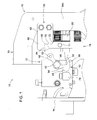
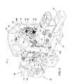
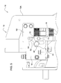
- a coupling assembly 10 is provided for coupling a towed implement to a vehicle or prime mover, in the present embodiment to a tractor used for agricultural work.
- a manifold or housing member 12 is mounted to a plate 14.
- Plate 14 is mounted on an outer housing 84 of a pickup hitch 80 of the tractor (see Figs. 7 and 8 ).
- An implement coupler unit 16 is fixed to a tongue 15 of the implement.
- the implement coupler unit 16 includes a base 17 and a coupler frame 19 with coupler frame arms 19A and 19B attached to sides of the base 17.
- An implement plate or coupler plate 18 is movably supported on the coupler frame 19.
- One or more hydraulic and/or electric implement couplers 20 are installed in the coupler plate 18.
- support brackets 22 project inwardly from the coupler frame arms 19A and 19B.
- Each bracket 22 has a bore 24 which receives a support bolt 26.
- Each support bolt 26 has a threaded end 28 which is threadably received by a corresponding threaded bore 30 in the coupler plate 18.
- a resilient spring member 32 such as a coil spring, is mounted around each support bolt 26, between the coupler plate 18 and each bracket 22. Each resilient spring member 32 is biased to urge the coupler plate 18 towards the housing member 12.
- Alignment dowels 34 project from the coupler plate 18 towards the housing member 12 and are received by alignment bores 36 formed in the housing member 12.
- the housing member 12 supports tractor couplers 40 which are matingly engagable with the implement couplers 20.
- the implement coupler unit 16 may be pulled towards the housing member 12 by a conventional pickup hitch 80 (see Figs. 7 and 8 ).
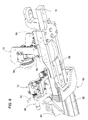
- a pivot pin 42 projects laterally from a side of the housing member 12.
- a lever member 44 is pivotally mounted on the pivot pin 42.
- the lever member 44 has a hub 46 which rotatably receives the pivot pin 42, a first arm 48 projecting away from the hub 46, and a second arm 50 projecting away from the hub 46.
- the lever member 42 also has a latch pin 52 which projects laterally away from an outer end of the first arm 48.
- the second arm 50 includes a first leg 54 which is joined to the hub 46 and a second leg 56 which extends away from the first leg 54.
- the first and second legs 54 and 56 are angled with respect to each other to form a locking recess 58.
- a latch member 60 is fixed, such as by bolts, to the implement coupler unit 16.
- the latch member 60 has a body 62, a latch finger 64 spaced apart from the body 62, and a spacer 66 which connects the latch finger 64 to the body 62.
- the body 62, the latch finger 64 and the spacer 66 form a slot 68 therebetween.
- the body 62 forms a slot wall 70 which is spaced apart from the latch finger 64 and which faces the latch finger 64.
- the body 62 also forms a latch wall 72 which is joined to the slot wall 70.
- a lock pin 71 projecting laterally from the coupler plate 18.
- a stop member 74 is formed by a hydraulic fitting which is attached to the housing member 12 spaced apart from the pivot pin 42.
- the lever member 44 has an uncoupled position wherein gravity moves the first arm 48 towards the latch member 60 and moves the second arm 50 into engagement with the stop member 74.
- a pair of alignment dowels 34 projects from the coupler plate 18.
- the housing member 12 includes alignment bores 36 which receive the alignment dowels 34.
- the latch wall 72 engages the latch pin 52 and pivots the lever member 44 and moves the latch pin 52 into the slot 68 as the implement coupler unit 16 moves towards the housing member 12. Also, the second arm 50 moves to a locking position wherein the locking recess 58 receives the lock pin 71 as the lever member 44 is pivoted by the latch member 60.
- the tractor pickup hitch 80 is mounted at the rear of a tractor frame part 82.
- the pickup hitch 80 supports the coupling assembly 10 which includes the plate 14 and the implement coupler unit 16.
- the pickup hitch 80 includes a fixed outer housing 84, a pivotal inner housing 86 and a drawbar 88 which is slidably received in the inner housing 86.
- a hitch ball 90 at the end of the drawbar 88 is received by a downward opening socket 92 which is formed by the base 17.
- the coupler frame 19 supports an implement PTO coupler member 94 which is releasably engagable with a vehicle PTO device 96.
- the result is a coupling assembly 10 which can automatically connect and lock flat face hydraulic quick couplers 20 and 40 together using a conventional production pickup hitch 80 without leaving the tractor cab.
- the hydraulic cylinder of a production pickup 80 hitch brings the hydraulic flat face quick couplers 20 and 40 together so that the coupling assembly 10 automatically mechanically locks the hydraulic flat face quick couplers 20 and 40 together.
- a coupler plate 18 supports the implement couplers 20 facing a housing member 12 which is attached to a plate 14 of the pickup hitch 80.
- Resilient spring members 32 movably hold the coupler plate 18 to a coupler frame 19 which is fixed to the implement.
- the coupler plate 18 contacts the housing member 12.
- the hydraulic cylinder continues to pull the coupler frame 19 towards the tractor, compressing the resilient spring members 32 and preventing damage to the hydraulic flat face quick couplers 20 and 40.
- This coupling assembly 10 complete the connection of the drawbar 88, PTO, hydraulic and electrical connections without requiring the operator to leave the cab.
Landscapes
- Engineering & Computer Science (AREA)
- Mechanical Engineering (AREA)
- Life Sciences & Earth Sciences (AREA)
- Transportation (AREA)
- Soil Sciences (AREA)
- Environmental Sciences (AREA)
- Zoology (AREA)
- Mining & Mineral Resources (AREA)
- Civil Engineering (AREA)
- General Engineering & Computer Science (AREA)
- Structural Engineering (AREA)
- Chemical & Material Sciences (AREA)
- Combustion & Propulsion (AREA)
- Agricultural Machines (AREA)
- Handcart (AREA)
Applications Claiming Priority (1)
| Application Number | Priority Date | Filing Date | Title |
|---|---|---|---|
| US14/520,692 US9357690B2 (en) | 2014-10-22 | 2014-10-22 | Tractor-implement coupling mechanism |
Publications (2)
| Publication Number | Publication Date |
|---|---|
| EP3012131A2 true EP3012131A2 (de) | 2016-04-27 |
| EP3012131A3 EP3012131A3 (de) | 2016-06-22 |
Family
ID=54266395
Family Applications (1)
| Application Number | Title | Priority Date | Filing Date |
|---|---|---|---|
| EP15188070.5A Withdrawn EP3012131A3 (de) | 2014-10-22 | 2015-10-02 | Kupplungsanordnung zum ankoppeln eines angehängten arbeitsgeräts an ein fahrzeug |
Country Status (2)
| Country | Link |
|---|---|
| US (1) | US9357690B2 (de) |
| EP (1) | EP3012131A3 (de) |
Cited By (1)
| Publication number | Priority date | Publication date | Assignee | Title |
|---|---|---|---|---|
| IT202000025828A1 (it) * | 2020-10-30 | 2022-04-30 | Faster Srl | Multiconnessione a piastra per il collegamento automatico di linee idrauliche |
Families Citing this family (10)
| Publication number | Priority date | Publication date | Assignee | Title |
|---|---|---|---|---|
| MX2019007052A (es) * | 2016-12-22 | 2020-01-27 | Polaris Inc | Fijacion rapida de toma de energia (pto) para vehiculo utilitario. |
| CN107558518B (zh) * | 2017-10-21 | 2023-04-07 | 盐城师范学院 | 可自动调整水平度的滩涂泥土平整装置 |
| DE102017126477A1 (de) | 2017-11-10 | 2019-05-16 | Syn Trac Gmbh | Kupplungsplatte |
| US10806066B2 (en) | 2018-05-18 | 2020-10-20 | Deere & Company | Implement multi-coupler with breakaway feature |
| CA3103021C (en) | 2018-06-15 | 2023-11-21 | Clark Equipment Company | Hydraulic coupling |
| DE102020110523A1 (de) * | 2020-04-17 | 2021-10-21 | Liebherr-Hydraulikbagger Gmbh | Schnellkupplung mit Zentriervorrichtung |
| US20230227113A1 (en) * | 2022-01-18 | 2023-07-20 | Zoomlion Heavy Industry Na, Inc. | Modular Hydraulic Cab And Frame System With A Universal Junction |
| US20250333123A1 (en) * | 2024-04-26 | 2025-10-30 | R.A. Phillips Industries, Inc. | Automatic coupling system |
| EP4670478A1 (de) * | 2024-06-28 | 2025-12-31 | Mark Duffy | Zapfwellen-/hydraulik-kupplungsvorrichtung |
| US12351019B1 (en) * | 2024-07-03 | 2025-07-08 | Caterpillar Inc. | Retainer for power take-off assembly |
Family Cites Families (14)
| Publication number | Priority date | Publication date | Assignee | Title |
|---|---|---|---|---|
| US2429761A (en) | 1946-06-17 | 1947-10-28 | Ketel Henry | Pintle hook |
| US4368899A (en) | 1981-03-16 | 1983-01-18 | Kansas State University Research Foundation | Hitch mechanism for tractors and implements |
| US4738463A (en) | 1987-02-24 | 1988-04-19 | Deere & Company | Automatically coupling fluid connector for a hitch |
| US4763743A (en) | 1987-06-01 | 1988-08-16 | Iowa State University Research Foundation, Inc. | Implement Hitch |
| DE4132889A1 (de) * | 1990-10-05 | 1992-04-09 | Erwin Roeder | Vorrichtung zum kuppeln eines antriebsfahrzeugs, insbes. schleppers, mit einem vom antriebsfahrzeug zu tragenden oder zu ziehenden geraet, wie anbaugeraet oder anhaenger |
| US5062321A (en) | 1991-03-11 | 1991-11-05 | General Motors Corporation | Control apparatus for regulating engagement of a fluid operated torque transmitting device |
| SE9600608L (sv) * | 1996-02-19 | 1997-02-17 | Kavlugnt Ab | Kopplingsanordning för sammankoppling av ett arbetsredskap till en arbetsmaskin; både mekanisk hopkoppling och snabbkoppling av hydraullikkopplingarna |
| US7290977B2 (en) * | 2005-03-09 | 2007-11-06 | Clark Equipment Company | Powered coupling of attachment hydraulics |
| US7717189B2 (en) | 2007-04-18 | 2010-05-18 | Kinze Manufacturing, Inc. | Planter with remote hydraulic feed |
| GB201000537D0 (en) | 2010-01-14 | 2010-03-03 | Agco Sa | Tractor implement support linkage |
| US8496070B2 (en) | 2010-09-20 | 2013-07-30 | Deere & Company | Folding hitch lift arm |
| US8770612B2 (en) * | 2012-04-19 | 2014-07-08 | Cnh Industrial America Llc | Automatic tractor hitch system for trailing implements |
| EP2676534B1 (de) | 2012-06-18 | 2015-04-08 | GGP Sweden AB | Befestigungsmittel |
| FR2995756B1 (fr) | 2012-09-24 | 2015-03-27 | Tracto Lock | Dispositif d'attelage d'un outil agricole sur un systeme de relevage trois points d'un tracteur agricole |
-
2014
- 2014-10-22 US US14/520,692 patent/US9357690B2/en active Active
-
2015
- 2015-10-02 EP EP15188070.5A patent/EP3012131A3/de not_active Withdrawn
Non-Patent Citations (1)
| Title |
|---|
| None |
Cited By (1)
| Publication number | Priority date | Publication date | Assignee | Title |
|---|---|---|---|---|
| IT202000025828A1 (it) * | 2020-10-30 | 2022-04-30 | Faster Srl | Multiconnessione a piastra per il collegamento automatico di linee idrauliche |
Also Published As
| Publication number | Publication date |
|---|---|
| US9357690B2 (en) | 2016-06-07 |
| US20160113188A1 (en) | 2016-04-28 |
| EP3012131A3 (de) | 2016-06-22 |
Similar Documents
| Publication | Publication Date | Title |
|---|---|---|
| US9357690B2 (en) | Tractor-implement coupling mechanism | |
| EP3011814B1 (de) | Kupplungsanordnung zum ankoppeln eines angehängten arbeitsgeräts an eine zugmaschine | |
| CN205086621U (zh) | 多用途拖车栓钩 | |
| CN111343851B (zh) | 具有对接插座和对接插件的对接装置,及车辆的连接方法 | |
| CA1295870C (en) | Automatically coupling fluid connector for a hitch | |
| US5193623A (en) | Hitching assemblies | |
| US20130020101A1 (en) | Quick connect/disconnect coupling for a stalk stomper | |
| US10156260B1 (en) | Power take-off quick coupler | |
| US2845281A (en) | Hitches | |
| EP3011816A1 (de) | Kupplungsanordnung zur verbindung eines propellerschafts eines arbeitsgeräts an einen zapfwellenantrieb eines traktors | |
| US9487928B1 (en) | Receiver plate-coupler plate assembly | |
| US3421780A (en) | Hitching device | |
| EP3012130B1 (de) | Kupplungsanordnung zur befestigung einer gerätes an einem fahrzeug | |
| EP3012127B1 (de) | Kupplungsanordnung zur befestigung einer gerätes an einem fahrzeug | |
| US7478823B2 (en) | Drawbar clevis assembly | |
| GB2479890A (en) | Three point coupler | |
| GB2512660A (en) | A quick hitch apparatus | |
| CN203401893U (zh) | 拖车挂接装置 | |
| US9121162B1 (en) | Motor coupler with multiple pick up locations | |
| KR100961612B1 (ko) | 트랙터용 농기구 연결장치 | |
| CN204442983U (zh) | 一种拖拉机的拖挂装置 | |
| CN201893476U (zh) | 一种汽车线束连接器 | |
| CN217839987U (zh) | 一种快拆式地插 | |
| US10736253B2 (en) | Hitch for connecting an implement to a vehicle | |
| CN211995046U (zh) | 拖挂装置 |
Legal Events
| Date | Code | Title | Description |
|---|---|---|---|
| PUAI | Public reference made under article 153(3) epc to a published international application that has entered the european phase |
Free format text: ORIGINAL CODE: 0009012 |
|
| AK | Designated contracting states |
Kind code of ref document: A2 Designated state(s): AL AT BE BG CH CY CZ DE DK EE ES FI FR GB GR HR HU IE IS IT LI LT LU LV MC MK MT NL NO PL PT RO RS SE SI SK SM TR |
|
| AX | Request for extension of the european patent |
Extension state: BA ME |
|
| PUAL | Search report despatched |
Free format text: ORIGINAL CODE: 0009013 |
|
| AK | Designated contracting states |
Kind code of ref document: A3 Designated state(s): AL AT BE BG CH CY CZ DE DK EE ES FI FR GB GR HR HU IE IS IT LI LT LU LV MC MK MT NL NO PL PT RO RS SE SI SK SM TR |
|
| AX | Request for extension of the european patent |
Extension state: BA ME |
|
| RIC1 | Information provided on ipc code assigned before grant |
Ipc: B60D 1/64 20060101ALI20160519BHEP Ipc: E02F 3/36 20060101ALI20160519BHEP Ipc: A01B 59/06 20060101ALI20160519BHEP Ipc: B60K 17/28 20060101ALI20160519BHEP Ipc: B60D 1/62 20060101AFI20160519BHEP Ipc: B60D 1/00 20060101ALI20160519BHEP Ipc: A01B 59/042 20060101ALI20160519BHEP |
|
| 17P | Request for examination filed |
Effective date: 20161222 |
|
| RBV | Designated contracting states (corrected) |
Designated state(s): AL AT BE BG CH CY CZ DE DK EE ES FI FR GB GR HR HU IE IS IT LI LT LU LV MC MK MT NL NO PL PT RO RS SE SI SK SM TR |
|
| STAA | Information on the status of an ep patent application or granted ep patent |
Free format text: STATUS: THE APPLICATION IS DEEMED TO BE WITHDRAWN |
|
| 18D | Application deemed to be withdrawn |
Effective date: 20161223 |