EP3012159B1 - Générateur de gaz destiné à un dispositif de retenue d'occupant - Google Patents
Générateur de gaz destiné à un dispositif de retenue d'occupant Download PDFInfo
- Publication number
- EP3012159B1 EP3012159B1 EP14814498.3A EP14814498A EP3012159B1 EP 3012159 B1 EP3012159 B1 EP 3012159B1 EP 14814498 A EP14814498 A EP 14814498A EP 3012159 B1 EP3012159 B1 EP 3012159B1
- Authority
- EP
- European Patent Office
- Prior art keywords
- cylindrical wall
- wall portion
- housing
- gas
- ignition device
- Prior art date
- Legal status (The legal status is an assumption and is not a legal conclusion. Google has not performed a legal analysis and makes no representation as to the accuracy of the status listed.)
- Active
Links
Images

Classifications
-
- B—PERFORMING OPERATIONS; TRANSPORTING
- B60—VEHICLES IN GENERAL
- B60R—VEHICLES, VEHICLE FITTINGS, OR VEHICLE PARTS, NOT OTHERWISE PROVIDED FOR
- B60R21/00—Arrangements or fittings on vehicles for protecting or preventing injuries to occupants or pedestrians in case of accidents or other traffic risks
- B60R21/02—Occupant safety arrangements or fittings, e.g. crash pads
- B60R21/16—Inflatable occupant restraints or confinements designed to inflate upon impact or impending impact, e.g. air bags
- B60R21/26—Inflatable occupant restraints or confinements designed to inflate upon impact or impending impact, e.g. air bags characterised by the inflation fluid source or means to control inflation fluid flow
- B60R21/264—Inflatable occupant restraints or confinements designed to inflate upon impact or impending impact, e.g. air bags characterised by the inflation fluid source or means to control inflation fluid flow using instantaneous generation of gas, e.g. pyrotechnic
-
- B—PERFORMING OPERATIONS; TRANSPORTING
- B60—VEHICLES IN GENERAL
- B60R—VEHICLES, VEHICLE FITTINGS, OR VEHICLE PARTS, NOT OTHERWISE PROVIDED FOR
- B60R21/00—Arrangements or fittings on vehicles for protecting or preventing injuries to occupants or pedestrians in case of accidents or other traffic risks
- B60R21/02—Occupant safety arrangements or fittings, e.g. crash pads
- B60R21/16—Inflatable occupant restraints or confinements designed to inflate upon impact or impending impact, e.g. air bags
- B60R21/26—Inflatable occupant restraints or confinements designed to inflate upon impact or impending impact, e.g. air bags characterised by the inflation fluid source or means to control inflation fluid flow
- B60R21/264—Inflatable occupant restraints or confinements designed to inflate upon impact or impending impact, e.g. air bags characterised by the inflation fluid source or means to control inflation fluid flow using instantaneous generation of gas, e.g. pyrotechnic
- B60R21/2644—Inflatable occupant restraints or confinements designed to inflate upon impact or impending impact, e.g. air bags characterised by the inflation fluid source or means to control inflation fluid flow using instantaneous generation of gas, e.g. pyrotechnic using only solid reacting substances, e.g. pellets, powder
-
- B—PERFORMING OPERATIONS; TRANSPORTING
- B60—VEHICLES IN GENERAL
- B60R—VEHICLES, VEHICLE FITTINGS, OR VEHICLE PARTS, NOT OTHERWISE PROVIDED FOR
- B60R21/00—Arrangements or fittings on vehicles for protecting or preventing injuries to occupants or pedestrians in case of accidents or other traffic risks
- B60R21/02—Occupant safety arrangements or fittings, e.g. crash pads
- B60R21/16—Inflatable occupant restraints or confinements designed to inflate upon impact or impending impact, e.g. air bags
- B60R21/26—Inflatable occupant restraints or confinements designed to inflate upon impact or impending impact, e.g. air bags characterised by the inflation fluid source or means to control inflation fluid flow
- B60R2021/26011—Inflatable occupant restraints or confinements designed to inflate upon impact or impending impact, e.g. air bags characterised by the inflation fluid source or means to control inflation fluid flow using a filter through which the inflation gas passes
-
- B—PERFORMING OPERATIONS; TRANSPORTING
- B60—VEHICLES IN GENERAL
- B60R—VEHICLES, VEHICLE FITTINGS, OR VEHICLE PARTS, NOT OTHERWISE PROVIDED FOR
- B60R21/00—Arrangements or fittings on vehicles for protecting or preventing injuries to occupants or pedestrians in case of accidents or other traffic risks
- B60R21/02—Occupant safety arrangements or fittings, e.g. crash pads
- B60R21/16—Inflatable occupant restraints or confinements designed to inflate upon impact or impending impact, e.g. air bags
- B60R21/26—Inflatable occupant restraints or confinements designed to inflate upon impact or impending impact, e.g. air bags characterised by the inflation fluid source or means to control inflation fluid flow
- B60R21/264—Inflatable occupant restraints or confinements designed to inflate upon impact or impending impact, e.g. air bags characterised by the inflation fluid source or means to control inflation fluid flow using instantaneous generation of gas, e.g. pyrotechnic
- B60R2021/2642—Inflatable occupant restraints or confinements designed to inflate upon impact or impending impact, e.g. air bags characterised by the inflation fluid source or means to control inflation fluid flow using instantaneous generation of gas, e.g. pyrotechnic comprising a plurality of combustion chambers or sub-chambers
-
- B—PERFORMING OPERATIONS; TRANSPORTING
- B60—VEHICLES IN GENERAL
- B60R—VEHICLES, VEHICLE FITTINGS, OR VEHICLE PARTS, NOT OTHERWISE PROVIDED FOR
- B60R21/00—Arrangements or fittings on vehicles for protecting or preventing injuries to occupants or pedestrians in case of accidents or other traffic risks
- B60R21/02—Occupant safety arrangements or fittings, e.g. crash pads
- B60R21/16—Inflatable occupant restraints or confinements designed to inflate upon impact or impending impact, e.g. air bags
- B60R21/26—Inflatable occupant restraints or confinements designed to inflate upon impact or impending impact, e.g. air bags characterised by the inflation fluid source or means to control inflation fluid flow
- B60R21/264—Inflatable occupant restraints or confinements designed to inflate upon impact or impending impact, e.g. air bags characterised by the inflation fluid source or means to control inflation fluid flow using instantaneous generation of gas, e.g. pyrotechnic
- B60R21/2644—Inflatable occupant restraints or confinements designed to inflate upon impact or impending impact, e.g. air bags characterised by the inflation fluid source or means to control inflation fluid flow using instantaneous generation of gas, e.g. pyrotechnic using only solid reacting substances, e.g. pellets, powder
- B60R2021/2648—Inflatable occupant restraints or confinements designed to inflate upon impact or impending impact, e.g. air bags characterised by the inflation fluid source or means to control inflation fluid flow using instantaneous generation of gas, e.g. pyrotechnic using only solid reacting substances, e.g. pellets, powder comprising a plurality of combustion chambers or sub-chambers
Definitions
- the present invention relates to a gas generator for a restraining device such as an airbag apparatus.
- a gas generator using a gas generating agent in which ignition and combustion ability of the gas generating agent charged into a combustion chamber are improved by adjusting the position of an ignition start portion in the combustion chamber and the outlet for discharging combustion gas from the combustion chamber.
- the gas generating agent 41 in combustion chamber 40 is ignited from a portion facing the ventilating portion 27 near the bottom plate 13a of the closure shell, the combustion gas is discharged from the porous member 50 which is an outlet of the combustion chamber 40. Therefore, the gas flows from the axially lower side to the upper side in the combustion chamber 40.
- the propellant chamber is separated into two chambers 62, 64 by the barrier 60.
- the propellant 40 in the propellant chamber 62 is directly burned by the igniter 24, but because of the barrier 60, flame from the igniter 24 does not reach a propellant 66 in the propellant chamber 64.
- the propellant 66 in the propellant chamber 64 is ignited by heat conduction from the propellant 40.
- US-A No. 5,009,855 discloses three gas generators depicted in Fig. 1 to Fig. 3 .
- the insert 9 is arranged in the combustion chamber 3.
- the insert 18 having the ball portion 20 is arranged inside the combustion chamber.
- the insert 29 is arranged in the combustion chamber.
- the combustion chamber is divided by the insert into the large chamber and the small chamber, and the gas generating agent is charged into each chamber.
- the gas generating agent in the small chamber is initially burned, the gas generated thereby is supplied to the large chamber, and the gas generating agent therein is burned.
- the present invention provides a gas generator for a restraining device, including:
- JP-A No. 2010-163025 the ignition and combustion ability of the gas generating agent inside the combustion chamber is improved, but since the invention of JP-A No. 2010-163025 is to improve the ignition ability such as to burn the gas generating agent in the combustion chamber at once, discharging the combustion gas so as to provide the S-shaped output curve such as described hereinabove goes against the invention of JP-A No. 2010-163025 .
- the combustion gas from a smaller-amount portion of gas generating agent 21 causes ignition of a larger-amount portion of gas generating agent 22 through an opening 23, and the inherent effects are difficult to obtain for the same reason as indicated in relation to Fig. 1 .
- the same is also true with respect to the gas generator depicted in Fig. 3 .
- the present invention is to provide a gas generator suitable for a restraining device such as an airbag apparatus, the gas generator using a single ignition device and making a difference in ignition start timings of the gas generating agent charged in the combustion chamber.
- the inner cylindrical wall portion is arranged inside the combustion chamber accommodating the gas generating agent, thereby providing, in the combustion chamber, a space (referred to hereinbelow as "a space for initial ignition") where the gas generating agent is ignited and burned relatively earlier and a space (referred to hereinbelow as "a space for late ignition”) where the gas generating agent is ignited and burned relatively later.
- the space for initial ignition is formed radially on the inner side of the inner cylindrical wall portion.
- the space for late ignition is formed radially on the outer side of the inner cylindrical wall portion.
- the first communication portion which communicates the ignition device chamber with the combustion chamber, directly faces the inner cylindrical wall portion in the radial direction of the housing.
- the height, from the bottom plate, of the upper end of the opening forming the first communication portion is preferably equal to or less than half of the height (h1) from the bottom plate to the upper end of the inner cylindrical wall portion.
- the ignition device in the ignition device chamber when the ignition device in the ignition device chamber is actuated and the combustion product (flame, combustion gas, etc.) is released from the first communication portion into the combustion chamber, the combustion product is released in the radial direction of the housing, the gas generating agent charged into the space for initial ignition is ignited and burned at first, and combustion gas is generated.
- the combustion product flame, combustion gas, etc.
- the combustion product released from the first communication portion causes combustion of the gas generating agent inside the space for initial ignition and then collides with the inner cylindrical wall portion.
- the combustion gas flows together with the combustion product toward the top plate and ignites the unburned gas generating agent present above the space for initial ignition in the X-axis direction (on the top plate side).
- the gas generated at this stage passes through the gas-flow hole formed in the annular partition wall portion and flows into the space formed above the combustion chamber.
- the gas generating agent present in the space for late ignition is located at a position opposite to the flow of the combustion gas in the X-axis direction, and the ignition thereof is delayed.
- a large number of the gas-flow holes can be uniformly formed in the annular partition wall portion, thereby controlling the block of passage of the combustion gas and the ignition of the gas generating agent in the space for late ignition caused by reflection of part of the gas generated in the space for initial ignition.
- the radially inner side with respect to the inner cylindrical wall portion, is taken as the space for initial ignition and is made to directly communicate with the first communication portion and the space for late ignition is formed on the radially outer side, the above-mentioned advantageous operation effects are easily obtained.
- the present invention preferably provides the gas generator for a restraining device, wherein the inner cylindrical wall portion meets at least Requirement (a) among requirements selected from following Requirements (a) to (c); and Requirement (a) is met by that a ratio (h1/h2) of a height (h1) from the bottom plate to the upper end of the inner cylindrical wall portion and a height (h2) from the bottom plate to the annular partition wall portion is within a range of 0.3 to 0.7;
- the inner cylindrical wall portion is arranged inside the combustion chamber, the space for initial ignition and the space for late ignition are formed, a time difference is created between ignition and combustion start timings of the gas generating agent charged into the combustion chamber, and the combustion gas is released such as to provide the abovementioned S-shaped output curve.
- Requirement (a) by adjusting Requirement (a) to a predetermined range, it is possible to adjust the difference between the ignition start timing of the gas generating agent charged into the space for initial ignition and the ignition start timing of the gas generating agent charged into the space for late ignition to a more desirable range.
- Requirement (b) is that a ratio (L1/L2) of a distance (L1) from the ignition device chamber housing to the inner cylindrical wall portion to a distance (L2) from the ignition device chamber housing to the outer cylindrical wall portion is within a range of 0.1 to 0.9, more preferably within a range of 0.3 to 0.7.
- L1 is determined by the maximum distance from the outer circumferential surface of the ignition device chamber housing to the outer circumferential surface of the inner cylindrical wall portion
- L2 is determined by the maximum distance from the outer circumferential surface of the ignition device chamber housing to the outer circumferential surface of the outer cylindrical wall portion
- Requirement (c) be that an angle between the bottom plate and the inner cylindrical wall portion on a side of the ignition device chamber housing is 70° to 140°.
- the present invention preferably provides the gas generator for a restraining device, wherein the inner cylindrical wall portion has a cylindrical wall surface and an outer annular flat surface extending outward in the radial direction of the housing from an outer circumferential edge at a lower end of the cylindrical wall surface; the outer cylindrical wall portion has a cylindrical wall surface and an inner annular flat surface extending inward in the radial direction of the housing from an inner circumferential edge at a lower end of the cylindrical wall surface; the inner cylindrical wall portion and the outer cylindrical wall portion is formed integrally at the outer annular flat surface and the inner annular flat surface; and an outer circumferential surface of the cylindrical wall surface of the outer cylindrical wall portion is fitted in a state of abutment against a circumferential wall of the housing where the gas discharge port is not formed.
- the two parts can be mounted together. Therefore the mounting operation is facilitated.
- the present invention preferably provides the gas generator for a restraining device, wherein the inner cylindrical wall portion has a cylindrical wall surface and an inner annular flat surface extending inward in the radial direction of the housing from an inner circumferential edge at a lower end of the cylindrical wall surface; and an inner circumferential edge of the inner annular flat surface of the inner cylindrical wall portion is fitted in a state of abutment against the ignition device or the ignition device chamber housing.
- the inner cylindrical wall portion is mounted such as to abut against the ignition device (the metallic collar fixing the igniter) or the ignition device chamber housing, positioning thereof is facilitated.
- the present invention preferably provides the gas generator for a restraining device, wherein the inner cylindrical wall portion has a cylindrical inclined wall surface inclined outward in the radial direction of the housing and an inner annular flat surface extending inward in the radial direction of the housing from an inner circumferential edge at a lower end of the inclined wall surface; and an inner circumferential edge of the inner annular flat surface of the inner cylindrical wall portion is fitted in a state of abutment against the ignition device or the ignition device chamber housing.
- the inner cylindrical wall portion is mounted such as to abut against the ignition device (the metallic collar fixing the igniter) or the ignition device chamber housing, positioning thereof is facilitated.
- the present invention preferably provides the gas generator for a restraining device, wherein the inner cylindrical wall portion has a cylindrical wall surface and an outer annular flat surface extending outward in the radial direction of the housing from an outer circumferential edge at a lower end of the cylindrical wall surface; a circumferential edge portion at the upper end of the cylindrical wall surface has depression and protrusion in the axial direction of the housing, the depression and protrusion are formed in a plurality of locations in the circumferential direction, and h1 in Requirement (a) is a height from the bottom plate to the depression of the cylindrical wall surface; the outer cylindrical wall portion has a cylindrical wall surface and an inner annular flat surface extending inward in the radial direction of the housing from an inner circumferential edge of the cylindrical wall surface; the inner cylindrical wall portion and the outer cylindrical wall portion are formed integrally at the outer annular flat surface and the inner annular flat surface; and an outer circumferential surface of the cylindrical wall surface of the outer cylindrical wall portion is fitted in a state of abutment
- Requirement (a) mentioned above is finely adjusted by using the inner cylindrical wall portion in which depressions and protrusions are formed at the cylindrical wall surface.
- the present invention preferably provides the gas generator for a restraining device, wherein the inner cylindrical wall portion has a cylindrical wall surface and an inner annular flat surface extending inward in the radial direction of the housing from an inner circumferential edge at a lower end of the cylindrical wall surface; a circumferential edge portion at the upper end of the cylindrical wall surface has depression and protrusion in the axial direction of the housing, and the depression and protrusion are formed in a plurality of locations in the circumferential direction; h1 in Requirement (a) is a height from the bottom plate to the depression of the cylindrical wall surface; an inner circumferential edge of the inner annular flat surface of the inner cylindrical wall portion is fitted in a state of abutment against the ignition device or the ignition device chamber housing.
- the inner cylindrical wall portion is mounted such as to abut against the ignition device (the metallic collar fixing the igniter) or the ignition device chamber housing, positioning thereof is facilitated.
- Requirements (a), (b) and (c) mentioned above are easily adjusted by adjusting the height and the angle of the cylindrical wall surface of the inner cylindrical wall portion, and the length of the inner annular flat surface.
- Requirement (a) mentioned above is finely adjusted by using the inner cylindrical wall portion in which depressions and protrusions are formed at the cylindrical wall surface.
- the present invention preferably provides the gas generator for a restraining device, wherein a plurality of through holes are formed in the circumferential direction in the cylindrical wall surface of the inner cylindrical wall portion; and h1 in Requirement (a) is a height from the bottom plate to a lower end circumferential edge of the through holes.
- Requirements (a), (b) and (c) mentioned above are easily adjusted by adjusting the height and the angle of the cylindrical wall surface and the length of the inner annular flat surface of the inner cylindrical wall portion.
- Requirement (a) mentioned above is finely adjusted by using the inner cylindrical wall portion in which through holes are formed in the cylindrical wall surface and adjusting the opening diameter, the number, and the shape of the through holes and also the height thereof from the bottom plate of the housing.
- the present invention preferably provides the gas generator for a restraining device, wherein an annular filter is disposed in a space between the top plate and the annular partition wall portion having the gas-flow hole.
- the filter is a known filter capable of filtering and cooling the combustion gas.
- the gas generator in accordance with the present invention With the gas generator in accordance with the present invention, a difference between ignition start timings of the gas generating agent charged into the combustion chamber is created even when the gas generating agent is ignited and burned with a single igniter. Therefore, the combustion gas is released and the airbag is inflated such as to provide the S-shaped output curve such as described hereinabove.
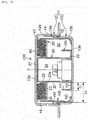
- a metallic housing 11 is obtained by welding and fixing a diffuser shell 12 to a closure shell 13 at a contact portion thereof.
- the diffuser shell 12 is in a cup-like shape having a top plate 12a and an upper circumferential wall portion 12b provided with a plurality of gas discharge ports 14.
- the gas discharge ports 14 are closed from the inner side with an aluminum tape for moisture prevention.
- the closure shell 13 is in a cup-like shape having a bottom plate 13a and a lower circumferential wall portion 13b.
- the circumferential wall of the housing 11 is formed by the upper circumferential wall portion 12b and the lower circumferential wall portion 13b.
- the closure shell 13 is fitted into the diffuser shell 12, and the contact portion of the shells are welded together and fixed (a welded fixed portion 15).
- An annular step 15a is formed at the inner circumferential surface of the welded fixed portion 15.
- An igniter 20 which is held by an igniter collar 21 and a resin 22, is disposed in the central portion of the bottom plate 13a of the closure shell 13.
- the igniter collar 21 is integrated with the bottom plate 13a, but may be a separate member welded to and integrated with the bottom plate.
- a tubular ignition device chamber housing 30 is disposed in the central portion of the housing 11 so as to cover the igniter 20 and the igniter collar 21.
- the interior of the ignition device chamber housing 30 corresponds to an ignition device chamber 34, accommodating therein a single igniter 20 and a transfer charge or a gas generating agent (not depicted in the drawing), which configure an ignition device.
- the tubular ignition device chamber housing 30 has a closing surface 31 on the top plate 12a side.
- the closing surface 31 is obtained by closing the opening of the housing 30 on the top plate 12a side with a separate member, or by closing the opening on the top plate 12a side by making the housing 30 abut against the top plate 12a.
- a cup-shaped housing may be used.
- An inner circumferential surface 32a of a circumferential wall 32 of the tubular ignition device chamber housing 30 is in contact with the igniter collar 21, except for part thereof (a non-contact portion).
- the inner circumferential surface 32a of the circumferential wall 32 and the igniter collar 21 may be fixed by a protrusion 36 protruding inward from the circumferential wall 32 to press against the igniter collar 21 as depicted in Fig. 1 .
- a passage 35 for combustion products which is a gap formed in the X-axis direction, is obtained in the non-contact portion of the inner circumferential surface 32a of the circumferential wall 32 and the igniter collar 21.
- a first communication portion 33 is formed in part of the circumferential wall 32 on the bottom plate 13a side.
- the first communication portion 33 is open and is not closed with a closing member such as a seal tape.
- the first communication portion 33 is a recess (a portion obtained by cutting out a circumferential edge) in the X-axis direction or a through-hole in the thickness direction, provided on the opening side of the circumferential wall 32.
- the first communication portion 33 communicates with the ignition device chamber 34 through the passage 35 for combustion products.
- An outer cylindrical wall portion 40 has a cylindrical wall surface 41 and an inner annular flat surface 42 that extends inward in the radial direction of the housing from the inner circumferential edge at the lower end (on the bottom plate 13a side) of the cylindrical wall surface 41.
- the inner annular flat surface 42 is in contact with the bottom plate 13a, and part of the cylindrical wall surface 41 abuts against the lower circumferential wall portion 13b of the closure shell 13.
- a cylindrical gas discharge path 16 communicating with the gas discharge port 14 is formed between the cylindrical wall surface 41 and the upper circumferential wall portion 12b of the diffuser shell 12.
- the outer cylindrical wall portion 40 has a second communication portion 43 formed by a cut-out portion obtained by partially cutting out the cylindrical wall surface 41 on the top plate 12a side, or opening.
- An annular partition wall portion 50 is arranged between the ignition device chamber housing 30 and the outer cylindrical wall portion 40 so that a space is formed between the top plate 12a and the annular partition wall portion.
- the annular partition wall portion 50 has an annular flat plate portion 51 having a plurality of gas-flow holes 53 and an annular wall 52 extending in the X-axis direction from the inner circumferential edge of the annular flat plate portion 51.
- the annular partition wall portion 50 is mounted by press-fitting the annular wall 52 to the ignition device chamber housing 30.
- the gas-flow holes 53 are formed uniformly over the entire annular flat plate portion 51 and have an opening area such as not to hinder the passage of the combustion gas from the gas generating agent.
- An annular filter 80 is disposed in the annular space formed between the top plate 12a and the annular partition wall portion 50.
- the annular filter 80 is a known filter that filters and cools the combustion gas generated by the gas generating agent.
- the space surrounded by the annular partition wall portion 50, the bottom plate 13a, the ignition device chamber housing 30 and the outer cylindrical wall portion 40 serves as a combustion chamber 60, and the combustion chamber 60 is filled with a known gas generating agent which is not depicted in the drawing.
- the combustion chamber 60 and the space formed by the annular partition wall portion 50 communicate with each other through the gas-flow holes 53 of the annular partition wall portion 50.
- An inner cylindrical wall portion 70 is further arranged inside the combustion chamber 60.
- the inner cylindrical wall portion 70 has a cylindrical wall surface 71 and an outer annular flat surface 72 that extends outward in the radial direction of the housing from the outer circumferential edge at the lower end (on the bottom plate 13a side) of the cylindrical wall surface 71.
- the inner cylindrical wall portion 70 is disposed such that the outer annular flat surface 72 is placed on the bottom plate 13a.
- the inner annular flat surface 42 and the outer annular flat surface 72 are unified, but they may be separate surfaces.
- the cylindrical wall surface 71 is arranged with a space apart from the ignition device chamber housing 30 and the outer cylindrical wall portion 40 and also with a space apart from the annular partition wall portion 50.
- the inner cylindrical wall portion 70 meets at least Requirement (a) among requirements selected from following Requirements (a) to (c).
- the height range of the inner cylindrical wall portion 70 in the axial direction of the housing from the bottom plate 13a is adjusted.
- a ratio (h1/h2) of the height (h1) from the bottom plate 13a to the upper end of the inner cylindrical wall portion 70 to the height (h2) from the bottom plate 13a to the annular partition wall portion 50 is within a range of 0.3 to 0.7.
- a ratio (L1/L2) of the distance (L1) from the ignition device chamber housing 30 to the inner cylindrical wall portion 70 to the distance (L2) from the ignition device chamber housing 30 to the outer cylindrical wall portion 40 is preferably within a range of 0.3 to 0.7.
- the inclination angle of the inner cylindrical wall portion 70 with respect to the bottom plate 13a is adjusted.
- the angle between the bottom plate 13a and the inner cylindrical wall portion 70 on the side of the ignition device chamber housing 30 is within a range of 70° to 140°.
- this angle is 90°.
- the inner cylindrical wall portion 70 (the cylindrical wall surface 71) and the first communication portion 33 face each other in the radial direction of the housing.
- the height of the upper end of the opening serving as the first communication portion 33 from the bottom plate 13a is preferably equal to or less than half of the height (h1) from the bottom plate 13a to the upper end of the inner cylindrical wall portion 70 (the cylindrical wall surface 71).
- the transfer charge or the gas generating agent is ignited and burned, and a combustion product (flame, combustion gas, etc.) is generated.
- the gas generating agent loaded into a space for initial ignition between the ignition device chamber housing 30 and the inner cylindrical wall portion 70 is ignited and burned.
- the space for the initial ignition is an annular space defined by the bottom plate 13a of the closure shell, the cylindrical wall surface 71 of the inner cylindrical wall portion and the circumferential wall 32 of the tubular ignition device chamber housing.
- the combustion products advance radially outward from the first communication portion 33 toward the interior of the combustion chamber 60 and collide with the inner cylindrical wall portion 70 (the cylindrical wall surface 71) facing the first communication portion 33.
- the flow direction thereof changes to the axial direction (the direction toward the top plate 12a, that is, toward the space where the filter 80 is arranged).
- the gas generating agent present in the space for the initial ignition (the space on the inner side of the cylindrical wall surface 71) is burned, and the combustion gas generated therefrom flows toward the top plate 12a. Therefore, the unburned gas generating agent present in this direction is also ignited.
- the gas generating agent charged into a space for late ignition (a space defined by the bottom plate 13a, the cylindrical wall surface 71 of the inner cylindrical wall portion and the cylindrical wall surface 41 of the outer cylindrical wall portion) is not present in the flow direction of the combustion gas and is unlikely to be ignited.
- the gas generating agent in the space for the initial ignition is ignited and burned to generate combustion gas and the combustion gas is discharged from the gas discharge port 14, and thereafter, the gas generating agent in the space for the late ignition is ignited and burned to generate combustion gas and the combustion gas is discharged from the gas discharge port 14. Therefore, the combustion gas is released and the airbag is inflated such as an S-shaped output curve is obtained.
- the combustion products change the flow direction by the cylindrical wall surface 71, and then flow linearly, while igniting and burning the gas generating agent present in the space for the initial ignition inside the combustion chamber 60, until the combustion products reach the space accommodating the filter 80 and communicating with the second communication portion 43. Therefore, the effect on the gas generating agent present in the space for the late ignition is small.
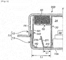
- a gas generator 100 depicted in Fig. 2 is different from the gas generator 10 depicted in Fig. 1 in the shape of the outer cylindrical wall portion and the shape and the mounting state of the inner cylindrical wall portion.
- Other features, including Requirements (a) to (c) are the same and the operation is the same.
- An outer cylindrical wall portion 140 has a cylindrical wall surface 141 and an inner annular flat surface 142 extending inward in the radial direction of the housing from the inner circumferential edge at the lower end (on the bottom plate 13a side) of the cylindrical wall surface.
- the inner annular flat surface 142 is in contact with the bottom plate 13a, and the cylindrical wall surface 141 abuts against the lower circumferential wall portion 13b of the closure shell 13.
- a cylindrical gas discharge path 16 communicating with the gas discharge port 14 is formed between the cylindrical wall surface 141 and the upper circumferential wall portion 12b of the diffuser shell 12.
- the outer cylindrical wall portion 140 has the second communication portion 43 formed by a cut-out portion obtained by cutting out part of the cylindrical wall surface 141 on the top plate 12a side, or an opening.
- An inner cylindrical wall portion 170 is disposed inside the combustion chamber 60.
- the inner cylindrical wall portion 170 has a cylindrical wall surface 171 and an inner annular flat surface 172 extending inward in the radial direction of the housing from the inner circumferential edge of the cylindrical wall surface 171.
- the inner annular flat surface 172 is placed on the bottom plate 13a and arranged in a state in which the inner circumferential edge thereof abuts against the circumferential wall 32 of the ignition device chamber housing 30.
- cylindrical wall surface 171 is disposed at a distance from the ignition device chamber housing 30 and the outer cylindrical wall portion 140, and at a distance from the annular partition wall portion 50 so that Requirements (a) to (c) are met.
- the inner circumferential edge of the inner annular flat surface 172 may abut against the igniter collar 21, and the opening of the ignition device chamber housing 30 may be placed on and abutted against the inner annular flat surface 172.
- a gas generator 200 depicted in Fig. 3 is different from the gas generator 100 depicted in Fig. 2 in the shape of the inner cylindrical wall portion. Other features are the same and the operation is the same.
- An inner cylindrical wall portion 270 is disposed inside the combustion chamber 60.
- the inner cylindrical wall portion 270 has a cylindrical wall surface 271 and an inner annular flat surface 272 extending inward in the radial direction of the housing from the inner circumferential edge of the lower end (on the bottom plate 13a side) of the cylindrical wall surface 271.
- the upper end side thereof is an inclined wall surface inclined radially outward.
- the inner cylindrical wall portion 270 depicted in Fig. 3 can be integrated with the outer cylindrical wall portion, in the same way as the inner cylindrical wall portion 70 depicted in Fig. 1 .
- the upper end side thereof is an inclined wall surface inclined radially inward.
- the inner annular flat surface 272 is placed on the bottom plate 13a and arranged in a state in which the inner circumferential edge thereof abuts against the circumferential wall 32 of the ignition device chamber housing 30.
- cylindrical wall surface 271 is disposed at a distance from the ignition device chamber housing 30 and the outer cylindrical wall portion 140 and at a distance from the annular partition wall portion 50 so that Requirements (a) to (c) are met.
- the inner circumferential edge of the inner annular flat surface 272 may abut against the igniter collar 21, and the opening of the ignition device chamber housing 30 may be placed on and abutted against the inner annular flat surface 272.
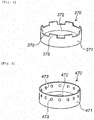
- An inner cylindrical wall portion 370 such as depicted in Fig. 4 can be used in the gas generators depicted in Fig. 2 and Fig. 3 .
- the inner cylindrical wall portion 370 has a cylindrical wall surface 371 and an inner annular flat surface 372 extending inward in the radial direction of the housing from the inner circumferential edge of the cylindrical wall surface 371.
- a circumferential edge portion at the upper end thereof has depressions 375 and protrusions 376 in the X-axis direction of the housing.
- the depressions 375 and the protrusions 376 are formed alternately in the circumferential direction.
- h1 in Requirement (a) is the height from the bottom plate 13a to the depression 375 of the cylindrical wall surface.
- inner cylindrical wall portion 370 depicted in Fig. 4 can be integrated with the outer cylindrical wall portion in the same way as the inner cylindrical wall portion 70 depicted in Fig. 1 .
- inner cylindrical wall portion 370 depicted in Fig. 4 can be provided with the inclined wall surface 271 depicted in Fig. 3 .
- An inner cylindrical wall portion 470 such as depicted in Fig. 5 can be used in the gas generators depicted in Fig. 2 and Fig. 3 .
- the inner cylindrical wall portion 470 has a cylindrical wall surface 471 and an inner annular flat surface 472 extending inward in the radial direction of the housing from the inner circumferential edge of the cylindrical wall surface 471.
- the cylindrical wall surface 471 has a plurality of through holes 473 in the thickness direction in the circumferential wall thereof.
- the through holes 473 are formed at the same height equidistantly in the circumferential direction.
- h1 in Requirement (a) is the height from the bottom plate 13a to the circumferential edge at a lower end of the through hole 473.
- inner cylindrical wall portion 470 depicted in Fig. 5 can be integrated with the outer cylindrical wall portion in the same way as the inner cylindrical wall portion 70 depicted in Fig. 1 .
- inner cylindrical wall portion 470 depicted in Fig. 5 can be provided with the inclined wall surface 271 depicted in Fig. 3 .
Landscapes
- Physics & Mathematics (AREA)
- Fluid Mechanics (AREA)
- Engineering & Computer Science (AREA)
- Mechanical Engineering (AREA)
- Air Bags (AREA)
- Feeding, Discharge, Calcimining, Fusing, And Gas-Generation Devices (AREA)
Claims (10)
- Générateur de gaz (10, 100, 200) pour un dispositif de retenue, comprenant:un boîtier (11) comprenant une plaque supérieure (12a), une paroi circonférentielle (12b) pourvue d'un orifice de décharge de gaz (14) et d'une plaque de fond (13a);un boîtier (30) de chambre de dispositif d'allumage tubulaire étant disposé à l'intérieur du boîtier (11) pour former une chambre de dispositif d'allumage (34), qui reçoit un dispositif d'allumage et une ouverture d'extrémité fermée;une partie de paroi cylindrique extérieure (40, 140) étant disposée de telle sorte qu'un circuit de décharge de gaz (16) en communication avec l'orifice de décharge de gaz (14) est formé entre la paroi circonférentielle (12b) et la portion de paroi cylindrique externe (40, 140);une partie de paroi de séparation annulaire (50) ayant un trou d'écoulement de gaz (53) et étant disposée entre le boîtier (30) de la chambre du dispositif d'allumage et la partie de paroi cylindrique externe (40, 140) pour former un espace avec la plaque supérieure (12a);une chambre de combustion (60) entourée par la plaque supérieure (12a), la plaque de fond (13a), le boîtier de chambre de dispositif d'allumage (30), et la partie de paroi cylindrique extérieure (40, 140) etétant remplie d'un agent générateur de gaz à l'intérieur de celle-ci;la chambre de combustion (60) et l'espace formé par la partie de paroi de séparation annulaire (50) en communication l'une avec l'autre par le trou d'écoulement de gaz (53) de la partie annulaire (50) de la paroi de séparation;caractérisé en ce que le générateur de gaz (10, 100, 200) pour le dispositif de retenue, comprend en outre:une partie interne (70, 170, 270, 370, 470) de paroi cylindrique disposée sur la plaque de fond (13a) et espacée du boitier de la chambre de dispositif d'allumage (30) et de la partie externe (40, 140) de la paroi cylindrique, et également à une certaine distance de la partie annulaire (50) de la paroi de séparation;la chambre de dispositif d'allumage (34) et la chambre de combustion (60) en communication l'une avec l'autre par une première partie de communication (33) formée par une ouverture prévue dans un partie de paroi circonférentielle du boîtier de la chambre d'allumage (30) sur le côté de la plaque de fond (13a);l'espace formé par la partie annulaire (50) de paroi de séparation et le circuit de décharge de gaz (16) qui communique avec l'orifice de décharge de gaz (14), en communication l'un avec l'autre par une seconde partie de communication (43) formée par une ouverture prévue entre la partie externe (40, 140) de paroi cylindrique et la plaque supérieure (12a); la première partie de communication (33) et la partie interne (70, 170, 270, 370, 470) de paroi cylindrique se faisant face dans une direction radiale du boîtier (11); etun produit de combustion, qui est généré dans la chambre de dispositif d'allumage (34), passant à travers la première partie de communication (33), puis entrant en collision avec la partie interne (70, 170, 270, 370, 470) de paroi cylindrique, changeant de sens d'écoulement vers la plaque supérieure (12a) où la seconde partie de communication (43) est prévue, et passant à travers le trou d'écoulement de gaz (53) de la partie annulaire (50) de la paroi de séparation.
- Générateur de gaz (10, 100, 200) pour dispositif de retenue selon la revendication 1, dans lequel
la partie interne (70, 170, 270, 370, 470) de paroi cylindrique satisfait au moins à l'exigence (a) parmi les exigences choisies parmi les exigences (a) à (c) suivantes; et l'exigence (a) est satisfaite par un rapport (h1/h2) d'une hauteur (hi) de la plaque de fond (13a) à l'extrémité supérieure de la partie de paroi cylindrique intérieure (70, 170, 270, 370, 470) et une hauteur (h2) allant de la plaque de fond (13a) à la partie annulaire (50) de paroi de séparation est comprise dans une plage de 0,3 à 0,7;(a) on règle une plage de hauteur de la partie interne (70, 70, 270, 370, 470) de paroi cylindrique dans le sens axial du boîtier (11) à partir de la plaque de fond (13a);(b) on règle une distance entre la partie interne (70, 170, 270, 370, 470) de paroi cylindrique et le boîtier de la chambre du dispositif d'allumage (30); et(c) on règle un angle d'inclinaison de la partie interne (70, 170, 270, 370, 470) de paroi cylindrique par rapport à la plaque de fond (13a). - Générateur de gaz (10) pour dispositif de retenue selon l'une des revendications 1 ou 2, dans lequel
la hauteur, à partir de la plaque de fond (13a), de l'extrémité supérieure de l'ouverture formant la première partie de communication (33) est inférieure ou égale à la moitié de la hauteur (hi) allant de la plaque de fond (13a) à l'extrémité supérieure de la partie interne (70) de paroi cylindrique. - Générateur de gaz (10) pour dispositif de retenue selon l'une des revendications 1 à 3, dans lequel
la partie interne (70) de paroi cylindrique présente une surface de paroi cylindrique (71) et une surface plane annulaire externe (72) se prolongeant vers l'extérieur dans la direction radiale du boîtier (11) à partir d'un bord périphérique externe à une extrémité inférieure de la surface de paroi cylindrique (71); la partie externe (40) de paroi cylindrique présente une surface de paroi cylindrique (41) et une surface plane annulaire externe (42) se prolongeant vers l'extérieur dans la direction radiale du boîtier (11) à partir d'un bord périphérique interne à une extrémité inférieure de la surface de paroi cylindrique (41);
la partie interne (70) de paroi cylindrique et la partie externe (40) de paroi cylindrique sont formées d'un seul tenant au niveau de la surface plane annulaire externe (72) et de la surface plate annulaire interne (42);
et
une surface circonférentielle externe de la surface de paroi cylindrique (71) de la partie externe (40) de la paroi cylindrique est montée en butée contre une paroi circonférentielle du boîtier (11) où l'orifice de décharge de gaz (14) n'est pas formé. - Générateur de gaz (100, 200) pour dispositif de retenue selon l'une quelconque des revendications 1 à 3, dans lequel
la partie interne (170, 270, 370, 470) de paroi cylindrique présente une surface de paroi cylindrique (141, 171, 271, 371, 471) et une surface plane annulaire interne (42) se prolongeant vers l'intérieur dans la direction radiale du boîtier (11) à partir d'un bord périphérique interne à une extrémité inférieure de la surface de paroi cylindrique (141, 171, 271, 371, 471); et un bord circonférentiel intérieur de la surface plate annulaire interne (142, 172, 272, 372, 472) de la partie interne (170, 270, 370, 470) de paroi cylindrique est monté en butée contre le dispositif d'allumage ou le boîtier de chambre de dispositif d'allumage (30). - Générateur de gaz (200) pour dispositif de retenue selon l'une des revendications 1 à 3, dans lequel
la partie interne (40) de paroi cylindrique présente une surface de paroi cylindrique inclinée (41) vers l'extérieur dans le sens radial du boîtier (11) et une surface plate annulaire interne (272) se prolongeant vers l'intérieur dans le sens radiale du boîtier (11) à partir d'un bord périphérique interne à une extrémité inférieure de la surface de paroi inclinée; et
un bord circonférentiel interne de la surface plate annulaire interne (272) de la partie interne (270) de paroi cylindrique est monté en butée contre le dispositif d'allumage ou le boîtier de chambre de dispositif d'allumage (30). - Générateur de gaz (10) pour dispositif de retenue selon la revendication 2, dans lequel
la partie interne (70) de paroi cylindrique présente une surface de paroi cylindrique (71) et une surface plane annulaire externe (72) se prolongeant vers l'extérieur dans la direction radiale du boîtier (11) à partir d'un bord périphérique externe à une extrémité inférieure de la surface de paroi cylindrique (71); une partie de bord circonférentiel à l'extrémité supérieure de la surface de paroi cylindrique (71) présente une dépression et une saillie dans la direction axiale du boîtier (11), la dépression et la saillie sont formées dans une pluralité d'emplacements dans la direction circonférentielle, et hi dans exigence (a) est une hauteur allant de la plaque de fond (13a) à la dépression de la surface de paroi cylindrique (71);
la partie externe (40) de paroi cylindrique présente une surface de paroi cylindrique (41) et une surface plane annulaire interne (42) se prolongeant vers l'intérieur dans la direction radiale du boîtier (11) à partir d'un bord périphérique interne de la surface de paroi cylindrique (41);
la partie interne (70) de paroi cylindrique et la partie externe (40) de paroi cylindrique sont formées d'un seul tenant au niveau de la surface plane annulaire externe (72) et de la surface plate annulaire interne (42); et
une surface circonférentielle externe de la surface de paroi cylindrique (71) de la partie externe (40) de la paroi cylindrique est montée en butée contre une paroi circonférentielle du boîtier (11) où l'orifice de décharge de gaz (14) n'est pas formé. - Générateur de gaz (10, 100, 200) pour dispositif de retenue selon la revendication 2, dans lequel
la partie interne (370) de paroi cylindrique présente une surface de paroi cylindrique (371) et une surface plane annulaire interne (372) se prolongeant vers l'intérieur dans la direction radiale du boîtier (11) à partir d'un bord périphérique interne à une extrémité inférieure de la surface de paroi cylindrique (371);
une partie de bord circonférentiel à l'extrémité supérieure de la surface de paroi cylindrique (71) présente une dépression (375) et une saillie (376) dans la direction axiale du boîtier (11), et la dépression (375) et la saillie (376) sont formées dans une pluralité d'emplacements dans le direction circonférentielle;
h 1 dans l'exigence (a) est une hauteur allant de la plaque de fond (13a) à la dépression (375) de la surface de paroi cylindrique (371);
un bord circonférentiel interne de la surface plate annulaire interne (372) de la partie interne (370) de paroi cylindrique est monté en butée contre le dispositif d'allumage ou le boîtier de chambre de dispositif d'allumage (30). - Générateur de gaz (10, 100, 200) pour dispositif de retenue selon la revendication 2, dans lequel
une pluralité de trous traversants (473) sont formées dans la direction circonférentielle dans la surface de paroi cylindrique (471) de la partie interne (470) de paroi cylindrique; et hi dans l'exigence (a) est un hauteur allant de la plaque de fond (13a) à un extrémité inférieure du bord périphérique du trou traversant (473). - Générateur de gaz (10, 100, 200) pour dispositif de retenue selon l'une quelconque des revendications 1 à 9, dans lequel un filtre annulaire (80) est disposé dans l'espace entre la plaque supérieure (12a) et la partie de paroi de séparation annulaire (50) comportant le trou d'écoulement de gaz (53).
Applications Claiming Priority (2)
| Application Number | Priority Date | Filing Date | Title |
|---|---|---|---|
| JP2013130727A JP6009997B2 (ja) | 2013-06-21 | 2013-06-21 | 人員拘束装置用ガス発生器 |
| PCT/JP2014/064702 WO2014203723A1 (fr) | 2013-06-21 | 2014-06-03 | Générateur de gaz destiné à un dispositif de retenue d'occupant |
Publications (3)
| Publication Number | Publication Date |
|---|---|
| EP3012159A1 EP3012159A1 (fr) | 2016-04-27 |
| EP3012159A4 EP3012159A4 (fr) | 2017-02-08 |
| EP3012159B1 true EP3012159B1 (fr) | 2018-01-31 |
Family
ID=52104464
Family Applications (1)
| Application Number | Title | Priority Date | Filing Date |
|---|---|---|---|
| EP14814498.3A Active EP3012159B1 (fr) | 2013-06-21 | 2014-06-03 | Générateur de gaz destiné à un dispositif de retenue d'occupant |
Country Status (6)
| Country | Link |
|---|---|
| US (1) | US9487182B2 (fr) |
| EP (1) | EP3012159B1 (fr) |
| JP (1) | JP6009997B2 (fr) |
| KR (1) | KR102162699B1 (fr) |
| CN (1) | CN105339215B (fr) |
| WO (1) | WO2014203723A1 (fr) |
Families Citing this family (13)
| Publication number | Priority date | Publication date | Assignee | Title |
|---|---|---|---|---|
| DE102008060305A1 (de) * | 2008-12-03 | 2010-06-10 | Trw Airbag Systems Gmbh | Gasgenerator |
| JP6009997B2 (ja) * | 2013-06-21 | 2016-10-19 | 株式会社ダイセル | 人員拘束装置用ガス発生器 |
| DE102013020526A1 (de) * | 2013-12-11 | 2015-06-11 | Trw Airbag Systems Gmbh | Polkörper für einen pyrotechnischen anzünder eines gasgenerators, anzünder, gasgenerator und gassackmodul mit einem derartigen polkörper |
| JP6276110B2 (ja) * | 2014-05-09 | 2018-02-07 | 株式会社ダイセル | ガス発生器とその組み立て方法 |
| JP6749788B2 (ja) * | 2016-05-18 | 2020-09-02 | 株式会社ダイセル | ガス発生器 |
| JP6701040B2 (ja) * | 2016-09-14 | 2020-05-27 | 日本化薬株式会社 | ガス発生器用フィルタおよびガス発生器 |
| JP6798935B2 (ja) | 2017-04-28 | 2020-12-09 | 日本化薬株式会社 | ガス発生器 |
| JP6797072B2 (ja) * | 2017-05-01 | 2020-12-09 | 株式会社ダイセル | ガス発生器 |
| JP6954520B2 (ja) * | 2017-12-05 | 2021-10-27 | 株式会社ダイセル | 点火器組立体、及びガス発生器 |
| KR102622079B1 (ko) * | 2018-05-29 | 2024-01-09 | 주식회사 다이셀 | 가스 발생기 |
| JP7368325B2 (ja) * | 2020-06-18 | 2023-10-24 | 株式会社ダイセル | ガス発生器 |
| JP7394715B2 (ja) * | 2020-06-30 | 2023-12-08 | 株式会社ダイセル | 部材固定構造及びガス発生器 |
| DE112023002800T5 (de) * | 2022-06-28 | 2025-06-12 | Daicel Corporation | Gasgenerator und Gasauslassverfahren für einen Gasgenerator |
Family Cites Families (32)
| Publication number | Priority date | Publication date | Assignee | Title |
|---|---|---|---|---|
| DE3835356A1 (de) | 1988-10-17 | 1990-04-19 | Bayern Chemie Gmbh Flugchemie | Gasgenerator |
| US5628528A (en) | 1995-07-06 | 1997-05-13 | Automotive Systems Laboratory, Inc. | Dual chamber nonazide gas generator |
| US6562161B1 (en) | 1997-03-24 | 2003-05-13 | Daicel Chemical Industries, Ltd. | Gas generating compositions for air bag |
| JP2000026189A (ja) | 1997-03-24 | 2000-01-25 | Daicel Chem Ind Ltd | エアバッグ用ガス発生剤組成物成型体 |
| US6227565B1 (en) * | 1999-03-04 | 2001-05-08 | Trw Inc. | Air bag inflator with pressure regulation |
| JP2002360607A (ja) | 2001-06-07 | 2002-12-17 | Ajs:Kk | 咬合器 |
| JP4700844B2 (ja) * | 2001-06-14 | 2011-06-15 | 日本化薬株式会社 | ガス発生器 |
| JP3965050B2 (ja) | 2001-12-26 | 2007-08-22 | ダイセル化学工業株式会社 | エアバッグ用ガス発生器 |
| US6948737B2 (en) | 2001-12-26 | 2005-09-27 | Daicel Chemical Industries, Ltd. | Gas generator for air bag |
| US20040046373A1 (en) * | 2002-09-09 | 2004-03-11 | Chung Shan Institute Of Science & Technology | Dual stage airbag inflator |
| US7052040B2 (en) * | 2002-12-09 | 2006-05-30 | Daicel Chemical Industries, Ltd | Gas generator for air bag |
| DE20219899U1 (de) * | 2002-12-23 | 2003-05-28 | TRW Airbag Systems GmbH, 84544 Aschau | Gasgenerator |
| EP1669259B1 (fr) * | 2004-12-08 | 2011-06-15 | Delphi Technologies, Inc. | Générateur de gaz |
| US7520530B2 (en) * | 2004-12-20 | 2009-04-21 | Daicel Chemical Industries, Ltd. | Gas generator for air bag |
| US7503581B2 (en) * | 2006-03-22 | 2009-03-17 | Daicel Chemical Industries, Ltd. | Gas generator for occupant restraining device for vehicle |
| JP4953838B2 (ja) * | 2007-01-26 | 2012-06-13 | 日本化薬株式会社 | ガス発生器 |
| DE102007033344A1 (de) * | 2007-07-16 | 2009-05-07 | Takata-Petri Ag | Gasgenerator für eine Fahrzeuginsassen-Schutzvorrichtung und Verfahren zum Entfernen von Feststoffen und flüssigen Abbrandresten in einem Gasstrom |
| JP5090100B2 (ja) * | 2007-08-09 | 2012-12-05 | 豊田合成株式会社 | インフレーター |
| FR2927291B1 (fr) * | 2008-02-07 | 2016-03-04 | Livbag | Generateur de gaz pour un dispositif de securite, dont la charge est initiee par un moyen generateur de chaleur. |
| JP5324931B2 (ja) * | 2009-01-15 | 2013-10-23 | 株式会社ダイセル | 車両の人員拘束装置用ガス発生器 |
| JP5016620B2 (ja) * | 2009-01-15 | 2012-09-05 | 株式会社ダイセル | 車両の人員拘束装置用ガス発生器 |
| JP5324930B2 (ja) | 2009-01-15 | 2013-10-23 | 株式会社ダイセル | 車両の人員拘束装置用ガス発生器 |
| JP5016619B2 (ja) * | 2009-01-15 | 2012-09-05 | 株式会社ダイセル | 車両の人員拘束装置用ガス発生器 |
| JP5528962B2 (ja) * | 2010-09-16 | 2014-06-25 | トヨタ自動車株式会社 | インフレータ |
| JP5922956B2 (ja) * | 2012-03-12 | 2016-05-24 | 株式会社ダイセル | ガス発生器 |
| JP5763000B2 (ja) * | 2012-03-19 | 2015-08-12 | 株式会社ダイセル | ガス発生器 |
| JP5873373B2 (ja) * | 2012-04-02 | 2016-03-01 | 株式会社ダイセル | ガス発生器 |
| JP5945152B2 (ja) * | 2012-04-25 | 2016-07-05 | 株式会社ダイセル | ガス発生器 |
| JP5912853B2 (ja) * | 2012-05-23 | 2016-04-27 | 株式会社ダイセル | ガス発生器 |
| JP6422628B2 (ja) * | 2012-10-18 | 2018-11-14 | 株式会社ダイセル | ガス発生剤組成物と、それを使用したガス発生器 |
| JP5956308B2 (ja) * | 2012-11-02 | 2016-07-27 | 株式会社ダイセル | 人員拘束装置用のガス発生器 |
| JP6009997B2 (ja) * | 2013-06-21 | 2016-10-19 | 株式会社ダイセル | 人員拘束装置用ガス発生器 |
-
2013
- 2013-06-21 JP JP2013130727A patent/JP6009997B2/ja not_active Expired - Fee Related
-
2014
- 2014-06-03 KR KR1020157034720A patent/KR102162699B1/ko active Active
- 2014-06-03 US US14/894,411 patent/US9487182B2/en active Active
- 2014-06-03 CN CN201480034293.3A patent/CN105339215B/zh active Active
- 2014-06-03 WO PCT/JP2014/064702 patent/WO2014203723A1/fr not_active Ceased
- 2014-06-03 EP EP14814498.3A patent/EP3012159B1/fr active Active
Non-Patent Citations (1)
| Title |
|---|
| None * |
Also Published As
| Publication number | Publication date |
|---|---|
| KR102162699B1 (ko) | 2020-10-07 |
| JP2015003650A (ja) | 2015-01-08 |
| JP6009997B2 (ja) | 2016-10-19 |
| EP3012159A4 (fr) | 2017-02-08 |
| US20160121841A1 (en) | 2016-05-05 |
| KR20160024859A (ko) | 2016-03-07 |
| WO2014203723A1 (fr) | 2014-12-24 |
| CN105339215B (zh) | 2017-12-26 |
| CN105339215A (zh) | 2016-02-17 |
| EP3012159A1 (fr) | 2016-04-27 |
| US9487182B2 (en) | 2016-11-08 |
Similar Documents
| Publication | Publication Date | Title |
|---|---|---|
| EP3012159B1 (fr) | Générateur de gaz destiné à un dispositif de retenue d'occupant | |
| EP2552753B1 (fr) | Générateur de gaz | |
| US9994190B2 (en) | Gas generator | |
| EP2531381B1 (fr) | Generatrice de gaz et son procede d'assemblage | |
| EP2957468B1 (fr) | Générateur de gaz | |
| US8011303B2 (en) | Gas generator | |
| US10981534B2 (en) | Gas generator | |
| US8087693B2 (en) | Gas generator | |
| EP2841312B1 (fr) | Générateur de gaz | |
| US10974687B2 (en) | Gas generator | |
| US10814828B2 (en) | Gas generator | |
| JP2004359031A (ja) | 多段着火式ガス発生器 | |
| EP2852515B1 (fr) | Générateur de gaz | |
| JP2004098980A (ja) | ガス発生器 | |
| JP2004098855A (ja) | ガス発生器 |
Legal Events
| Date | Code | Title | Description |
|---|---|---|---|
| PUAI | Public reference made under article 153(3) epc to a published international application that has entered the european phase |
Free format text: ORIGINAL CODE: 0009012 |
|
| 17P | Request for examination filed |
Effective date: 20151214 |
|
| AK | Designated contracting states |
Kind code of ref document: A1 Designated state(s): AL AT BE BG CH CY CZ DE DK EE ES FI FR GB GR HR HU IE IS IT LI LT LU LV MC MK MT NL NO PL PT RO RS SE SI SK SM TR |
|
| AX | Request for extension of the european patent |
Extension state: BA ME |
|
| DAX | Request for extension of the european patent (deleted) | ||
| A4 | Supplementary search report drawn up and despatched |
Effective date: 20170111 |
|
| RIC1 | Information provided on ipc code assigned before grant |
Ipc: B60R 21/264 20060101AFI20170104BHEP |
|
| GRAP | Despatch of communication of intention to grant a patent |
Free format text: ORIGINAL CODE: EPIDOSNIGR1 |
|
| INTG | Intention to grant announced |
Effective date: 20170831 |
|
| GRAS | Grant fee paid |
Free format text: ORIGINAL CODE: EPIDOSNIGR3 |
|
| GRAA | (expected) grant |
Free format text: ORIGINAL CODE: 0009210 |
|
| RIN1 | Information on inventor provided before grant (corrected) |
Inventor name: KATSUTA, TAKASHI |
|
| AK | Designated contracting states |
Kind code of ref document: B1 Designated state(s): AL AT BE BG CH CY CZ DE DK EE ES FI FR GB GR HR HU IE IS IT LI LT LU LV MC MK MT NL NO PL PT RO RS SE SI SK SM TR |
|
| REG | Reference to a national code |
Ref country code: GB Ref legal event code: FG4D Ref country code: CH Ref legal event code: EP |
|
| REG | Reference to a national code |
Ref country code: AT Ref legal event code: REF Ref document number: 967046 Country of ref document: AT Kind code of ref document: T Effective date: 20180215 |
|
| REG | Reference to a national code |
Ref country code: IE Ref legal event code: FG4D |
|
| REG | Reference to a national code |
Ref country code: DE Ref legal event code: R096 Ref document number: 602014020571 Country of ref document: DE |
|
| REG | Reference to a national code |
Ref country code: NL Ref legal event code: MP Effective date: 20180131 |
|
| REG | Reference to a national code |
Ref country code: LT Ref legal event code: MG4D |
|
| REG | Reference to a national code |
Ref country code: AT Ref legal event code: MK05 Ref document number: 967046 Country of ref document: AT Kind code of ref document: T Effective date: 20180131 |
|
| PG25 | Lapsed in a contracting state [announced via postgrant information from national office to epo] |
Ref country code: NO Free format text: LAPSE BECAUSE OF FAILURE TO SUBMIT A TRANSLATION OF THE DESCRIPTION OR TO PAY THE FEE WITHIN THE PRESCRIBED TIME-LIMIT Effective date: 20180430 Ref country code: FI Free format text: LAPSE BECAUSE OF FAILURE TO SUBMIT A TRANSLATION OF THE DESCRIPTION OR TO PAY THE FEE WITHIN THE PRESCRIBED TIME-LIMIT Effective date: 20180131 Ref country code: HR Free format text: LAPSE BECAUSE OF FAILURE TO SUBMIT A TRANSLATION OF THE DESCRIPTION OR TO PAY THE FEE WITHIN THE PRESCRIBED TIME-LIMIT Effective date: 20180131 Ref country code: NL Free format text: LAPSE BECAUSE OF FAILURE TO SUBMIT A TRANSLATION OF THE DESCRIPTION OR TO PAY THE FEE WITHIN THE PRESCRIBED TIME-LIMIT Effective date: 20180131 Ref country code: LT Free format text: LAPSE BECAUSE OF FAILURE TO SUBMIT A TRANSLATION OF THE DESCRIPTION OR TO PAY THE FEE WITHIN THE PRESCRIBED TIME-LIMIT Effective date: 20180131 Ref country code: ES Free format text: LAPSE BECAUSE OF FAILURE TO SUBMIT A TRANSLATION OF THE DESCRIPTION OR TO PAY THE FEE WITHIN THE PRESCRIBED TIME-LIMIT Effective date: 20180131 |
|
| PG25 | Lapsed in a contracting state [announced via postgrant information from national office to epo] |
Ref country code: PL Free format text: LAPSE BECAUSE OF FAILURE TO SUBMIT A TRANSLATION OF THE DESCRIPTION OR TO PAY THE FEE WITHIN THE PRESCRIBED TIME-LIMIT Effective date: 20180131 Ref country code: IS Free format text: LAPSE BECAUSE OF FAILURE TO SUBMIT A TRANSLATION OF THE DESCRIPTION OR TO PAY THE FEE WITHIN THE PRESCRIBED TIME-LIMIT Effective date: 20180531 Ref country code: SE Free format text: LAPSE BECAUSE OF FAILURE TO SUBMIT A TRANSLATION OF THE DESCRIPTION OR TO PAY THE FEE WITHIN THE PRESCRIBED TIME-LIMIT Effective date: 20180131 Ref country code: LV Free format text: LAPSE BECAUSE OF FAILURE TO SUBMIT A TRANSLATION OF THE DESCRIPTION OR TO PAY THE FEE WITHIN THE PRESCRIBED TIME-LIMIT Effective date: 20180131 Ref country code: BG Free format text: LAPSE BECAUSE OF FAILURE TO SUBMIT A TRANSLATION OF THE DESCRIPTION OR TO PAY THE FEE WITHIN THE PRESCRIBED TIME-LIMIT Effective date: 20180430 Ref country code: AT Free format text: LAPSE BECAUSE OF FAILURE TO SUBMIT A TRANSLATION OF THE DESCRIPTION OR TO PAY THE FEE WITHIN THE PRESCRIBED TIME-LIMIT Effective date: 20180131 Ref country code: RS Free format text: LAPSE BECAUSE OF FAILURE TO SUBMIT A TRANSLATION OF THE DESCRIPTION OR TO PAY THE FEE WITHIN THE PRESCRIBED TIME-LIMIT Effective date: 20180131 Ref country code: GR Free format text: LAPSE BECAUSE OF FAILURE TO SUBMIT A TRANSLATION OF THE DESCRIPTION OR TO PAY THE FEE WITHIN THE PRESCRIBED TIME-LIMIT Effective date: 20180501 |
|
| PG25 | Lapsed in a contracting state [announced via postgrant information from national office to epo] |
Ref country code: EE Free format text: LAPSE BECAUSE OF FAILURE TO SUBMIT A TRANSLATION OF THE DESCRIPTION OR TO PAY THE FEE WITHIN THE PRESCRIBED TIME-LIMIT Effective date: 20180131 Ref country code: IT Free format text: LAPSE BECAUSE OF FAILURE TO SUBMIT A TRANSLATION OF THE DESCRIPTION OR TO PAY THE FEE WITHIN THE PRESCRIBED TIME-LIMIT Effective date: 20180131 Ref country code: AL Free format text: LAPSE BECAUSE OF FAILURE TO SUBMIT A TRANSLATION OF THE DESCRIPTION OR TO PAY THE FEE WITHIN THE PRESCRIBED TIME-LIMIT Effective date: 20180131 Ref country code: RO Free format text: LAPSE BECAUSE OF FAILURE TO SUBMIT A TRANSLATION OF THE DESCRIPTION OR TO PAY THE FEE WITHIN THE PRESCRIBED TIME-LIMIT Effective date: 20180131 |
|
| REG | Reference to a national code |
Ref country code: DE Ref legal event code: R097 Ref document number: 602014020571 Country of ref document: DE |
|
| PG25 | Lapsed in a contracting state [announced via postgrant information from national office to epo] |
Ref country code: CZ Free format text: LAPSE BECAUSE OF FAILURE TO SUBMIT A TRANSLATION OF THE DESCRIPTION OR TO PAY THE FEE WITHIN THE PRESCRIBED TIME-LIMIT Effective date: 20180131 Ref country code: SM Free format text: LAPSE BECAUSE OF FAILURE TO SUBMIT A TRANSLATION OF THE DESCRIPTION OR TO PAY THE FEE WITHIN THE PRESCRIBED TIME-LIMIT Effective date: 20180131 Ref country code: SK Free format text: LAPSE BECAUSE OF FAILURE TO SUBMIT A TRANSLATION OF THE DESCRIPTION OR TO PAY THE FEE WITHIN THE PRESCRIBED TIME-LIMIT Effective date: 20180131 Ref country code: DK Free format text: LAPSE BECAUSE OF FAILURE TO SUBMIT A TRANSLATION OF THE DESCRIPTION OR TO PAY THE FEE WITHIN THE PRESCRIBED TIME-LIMIT Effective date: 20180131 |
|
| PLBE | No opposition filed within time limit |
Free format text: ORIGINAL CODE: 0009261 |
|
| STAA | Information on the status of an ep patent application or granted ep patent |
Free format text: STATUS: NO OPPOSITION FILED WITHIN TIME LIMIT |
|
| 26N | No opposition filed |
Effective date: 20181102 |
|
| REG | Reference to a national code |
Ref country code: CH Ref legal event code: PL |
|
| GBPC | Gb: european patent ceased through non-payment of renewal fee |
Effective date: 20180603 |
|
| PG25 | Lapsed in a contracting state [announced via postgrant information from national office to epo] |
Ref country code: SI Free format text: LAPSE BECAUSE OF FAILURE TO SUBMIT A TRANSLATION OF THE DESCRIPTION OR TO PAY THE FEE WITHIN THE PRESCRIBED TIME-LIMIT Effective date: 20180131 |
|
| REG | Reference to a national code |
Ref country code: BE Ref legal event code: MM Effective date: 20180630 |
|
| REG | Reference to a national code |
Ref country code: IE Ref legal event code: MM4A |
|
| PG25 | Lapsed in a contracting state [announced via postgrant information from national office to epo] |
Ref country code: MC Free format text: LAPSE BECAUSE OF FAILURE TO SUBMIT A TRANSLATION OF THE DESCRIPTION OR TO PAY THE FEE WITHIN THE PRESCRIBED TIME-LIMIT Effective date: 20180131 Ref country code: LU Free format text: LAPSE BECAUSE OF NON-PAYMENT OF DUE FEES Effective date: 20180603 |
|
| PG25 | Lapsed in a contracting state [announced via postgrant information from national office to epo] |
Ref country code: FR Free format text: LAPSE BECAUSE OF NON-PAYMENT OF DUE FEES Effective date: 20180630 Ref country code: GB Free format text: LAPSE BECAUSE OF NON-PAYMENT OF DUE FEES Effective date: 20180603 Ref country code: IE Free format text: LAPSE BECAUSE OF NON-PAYMENT OF DUE FEES Effective date: 20180603 Ref country code: CH Free format text: LAPSE BECAUSE OF NON-PAYMENT OF DUE FEES Effective date: 20180630 Ref country code: LI Free format text: LAPSE BECAUSE OF NON-PAYMENT OF DUE FEES Effective date: 20180630 |
|
| PG25 | Lapsed in a contracting state [announced via postgrant information from national office to epo] |
Ref country code: BE Free format text: LAPSE BECAUSE OF NON-PAYMENT OF DUE FEES Effective date: 20180630 |
|
| PG25 | Lapsed in a contracting state [announced via postgrant information from national office to epo] |
Ref country code: MT Free format text: LAPSE BECAUSE OF NON-PAYMENT OF DUE FEES Effective date: 20180603 |
|
| PG25 | Lapsed in a contracting state [announced via postgrant information from national office to epo] |
Ref country code: TR Free format text: LAPSE BECAUSE OF FAILURE TO SUBMIT A TRANSLATION OF THE DESCRIPTION OR TO PAY THE FEE WITHIN THE PRESCRIBED TIME-LIMIT Effective date: 20180131 |
|
| PG25 | Lapsed in a contracting state [announced via postgrant information from national office to epo] |
Ref country code: PT Free format text: LAPSE BECAUSE OF FAILURE TO SUBMIT A TRANSLATION OF THE DESCRIPTION OR TO PAY THE FEE WITHIN THE PRESCRIBED TIME-LIMIT Effective date: 20180131 |
|
| PG25 | Lapsed in a contracting state [announced via postgrant information from national office to epo] |
Ref country code: CY Free format text: LAPSE BECAUSE OF FAILURE TO SUBMIT A TRANSLATION OF THE DESCRIPTION OR TO PAY THE FEE WITHIN THE PRESCRIBED TIME-LIMIT Effective date: 20180131 Ref country code: MK Free format text: LAPSE BECAUSE OF NON-PAYMENT OF DUE FEES Effective date: 20180131 Ref country code: HU Free format text: LAPSE BECAUSE OF FAILURE TO SUBMIT A TRANSLATION OF THE DESCRIPTION OR TO PAY THE FEE WITHIN THE PRESCRIBED TIME-LIMIT; INVALID AB INITIO Effective date: 20140603 |
|
| PGFP | Annual fee paid to national office [announced via postgrant information from national office to epo] |
Ref country code: DE Payment date: 20250618 Year of fee payment: 12 |