EP3012187B1 - Aktiv gesteuerte superhydrophobe oberflächen - Google Patents
Aktiv gesteuerte superhydrophobe oberflächen Download PDFInfo
- Publication number
- EP3012187B1 EP3012187B1 EP15190974.4A EP15190974A EP3012187B1 EP 3012187 B1 EP3012187 B1 EP 3012187B1 EP 15190974 A EP15190974 A EP 15190974A EP 3012187 B1 EP3012187 B1 EP 3012187B1
- Authority
- EP
- European Patent Office
- Prior art keywords
- superhydrophobic
- controlled
- active
- state
- controlled region
- Prior art date
- Legal status (The legal status is an assumption and is not a legal conclusion. Google has not performed a legal analysis and makes no representation as to the accuracy of the status listed.)
- Active
Links
Images


Classifications
-
- B—PERFORMING OPERATIONS; TRANSPORTING
- B64—AIRCRAFT; AVIATION; COSMONAUTICS
- B64C—AEROPLANES; HELICOPTERS
- B64C21/00—Influencing air flow over aircraft surfaces by affecting boundary layer flow
- B64C21/10—Influencing air flow over aircraft surfaces by affecting boundary layer flow using other surface properties, e.g. roughness
-
- B—PERFORMING OPERATIONS; TRANSPORTING
- B08—CLEANING
- B08B—CLEANING IN GENERAL; PREVENTION OF FOULING IN GENERAL
- B08B17/00—Methods preventing fouling
- B08B17/02—Preventing deposition of fouling or of dust
- B08B17/06—Preventing deposition of fouling or of dust by giving articles subject to fouling a special shape or arrangement
- B08B17/065—Preventing deposition of fouling or of dust by giving articles subject to fouling a special shape or arrangement the surface having a microscopic surface pattern to achieve the same effect as a lotus flower
-
- B—PERFORMING OPERATIONS; TRANSPORTING
- B64—AIRCRAFT; AVIATION; COSMONAUTICS
- B64D—EQUIPMENT FOR FITTING IN OR TO AIRCRAFT; FLIGHT SUITS; PARACHUTES; ARRANGEMENT OR MOUNTING OF POWER PLANTS OR PROPULSION TRANSMISSIONS IN AIRCRAFT
- B64D15/00—De-icing or preventing icing on exterior surfaces of aircraft
-
- B—PERFORMING OPERATIONS; TRANSPORTING
- B64—AIRCRAFT; AVIATION; COSMONAUTICS
- B64D—EQUIPMENT FOR FITTING IN OR TO AIRCRAFT; FLIGHT SUITS; PARACHUTES; ARRANGEMENT OR MOUNTING OF POWER PLANTS OR PROPULSION TRANSMISSIONS IN AIRCRAFT
- B64D15/00—De-icing or preventing icing on exterior surfaces of aircraft
- B64D15/12—De-icing or preventing icing on exterior surfaces of aircraft by electric heating
-
- B—PERFORMING OPERATIONS; TRANSPORTING
- B64—AIRCRAFT; AVIATION; COSMONAUTICS
- B64D—EQUIPMENT FOR FITTING IN OR TO AIRCRAFT; FLIGHT SUITS; PARACHUTES; ARRANGEMENT OR MOUNTING OF POWER PLANTS OR PROPULSION TRANSMISSIONS IN AIRCRAFT
- B64D15/00—De-icing or preventing icing on exterior surfaces of aircraft
- B64D15/16—De-icing or preventing icing on exterior surfaces of aircraft by mechanical means, e.g. pulsating mats or shoes attached to, or built into, surface
- B64D15/163—De-icing or preventing icing on exterior surfaces of aircraft by mechanical means, e.g. pulsating mats or shoes attached to, or built into, surface using electro-impulsive devices
-
- B—PERFORMING OPERATIONS; TRANSPORTING
- B81—MICROSTRUCTURAL TECHNOLOGY
- B81B—MICROSTRUCTURAL DEVICES OR SYSTEMS, e.g. MICROMECHANICAL DEVICES
- B81B3/00—Devices comprising flexible or deformable elements, e.g. comprising elastic tongues or membranes
- B81B3/0064—Constitution or structural means for improving or controlling the physical properties of a device
- B81B3/0094—Constitution or structural means for improving or controlling physical properties not provided for in B81B3/0067 - B81B3/0091
-
- B—PERFORMING OPERATIONS; TRANSPORTING
- B81—MICROSTRUCTURAL TECHNOLOGY
- B81B—MICROSTRUCTURAL DEVICES OR SYSTEMS, e.g. MICROMECHANICAL DEVICES
- B81B7/00—Microstructural systems ; Auxiliary parts of microstructural devices or systems
- B81B7/0009—Structural features, others than packages, for protecting a device against environmental influences
- B81B7/0029—Protection against environmental influences not provided for in groups B81B7/0012 - B81B7/0025
-
- B—PERFORMING OPERATIONS; TRANSPORTING
- B81—MICROSTRUCTURAL TECHNOLOGY
- B81B—MICROSTRUCTURAL DEVICES OR SYSTEMS, e.g. MICROMECHANICAL DEVICES
- B81B7/00—Microstructural systems ; Auxiliary parts of microstructural devices or systems
- B81B7/02—Microstructural systems ; Auxiliary parts of microstructural devices or systems containing distinct electrical or optical devices of particular relevance for their function, e.g. microelectro-mechanical systems [MEMS]
-
- B—PERFORMING OPERATIONS; TRANSPORTING
- B81—MICROSTRUCTURAL TECHNOLOGY
- B81B—MICROSTRUCTURAL DEVICES OR SYSTEMS, e.g. MICROMECHANICAL DEVICES
- B81B7/00—Microstructural systems ; Auxiliary parts of microstructural devices or systems
- B81B7/04—Networks or arrays of similar microstructural devices
-
- B—PERFORMING OPERATIONS; TRANSPORTING
- B81—MICROSTRUCTURAL TECHNOLOGY
- B81C—PROCESSES OR APPARATUS SPECIALLY ADAPTED FOR THE MANUFACTURE OR TREATMENT OF MICROSTRUCTURAL DEVICES OR SYSTEMS
- B81C1/00—Manufacture or treatment of devices or systems in or on a substrate
- B81C1/00015—Manufacture or treatment of devices or systems in or on a substrate for manufacturing microsystems
- B81C1/00206—Processes for functionalising a surface, e.g. provide the surface with specific mechanical, chemical or biological properties
-
- Y—GENERAL TAGGING OF NEW TECHNOLOGICAL DEVELOPMENTS; GENERAL TAGGING OF CROSS-SECTIONAL TECHNOLOGIES SPANNING OVER SEVERAL SECTIONS OF THE IPC; TECHNICAL SUBJECTS COVERED BY FORMER USPC CROSS-REFERENCE ART COLLECTIONS [XRACs] AND DIGESTS
- Y02—TECHNOLOGIES OR APPLICATIONS FOR MITIGATION OR ADAPTATION AGAINST CLIMATE CHANGE
- Y02T—CLIMATE CHANGE MITIGATION TECHNOLOGIES RELATED TO TRANSPORTATION
- Y02T50/00—Aeronautics or air transport
- Y02T50/10—Drag reduction
Definitions
- the present disclosure relates to actively-controlled superhydrophobic surfaces.
- Superhydrophobicity is a physical property of a surface on which wetting is relatively difficult. Water drops on a superhydrophobic surface tend to bead and roll off the surface rather than stick to the surface. Superhydrophobic surfaces also may be ice resistant (e.g., due to a lack of water on the surface) and/or self-cleaning (e.g., due to water on the surface carrying away contaminants).
- Water, ice, and surface contamination are significant problems in various industries including transportation, power, buildings, and consumer products.
- ice accumulation can reduce the performance of aircraft, watercraft, and wind turbines.
- solar panels and electronic displays are subject to surface contamination that reduces performance and/or usability.
- superhydrophobic surfaces may be beneficial in some situations (such as during use, cleaning, wet conditions, condensing conditions, and/or icing conditions), in other situations a superhydrophobic surface may reduce performance and/or utility of an apparatus.
- Conventional superhydrophobic surface structures are passive structures and generally relatively delicate structures.
- the superhydrophobic surface structure may wear with use and/or may be damaged by use.
- many industrial and consumer uses subject devices to harsh conditions e.g., thermal, abrasive, and/or chemical conditions such as may be experienced during environmental exposure, repeated handling, icing conditions, and/or high speed flight). Once sufficiently worn or damaged, the superhydrophobic surface structure loses its superhydrophobicity and therefore its effectiveness.
- Active superhydrophobic surface structures are actively-controlled surface structures exhibiting a superhydrophobic state and an ordinary state.
- Active superhydrophobic surface structures comprise an outer elastomeric covering defining an exposed surface, a controlled group of one or more MEMS (micro-electro-mechanical system) actuators at least covered by the elastomeric covering, and, a controlled region of the exposed surface corresponding to the controlled group.
- the controlled region has a superhydrophobic state in which the controlled region is textured.
- the controlled region also has an ordinary state in which the controlled region is smooth (i.e., less textured than in the superhydrophobic state).
- Active superhydrophobic surface structures may be a component of an apparatus such as a vehicle (e.g., an aircraft).
- the apparatus may include a controller and/or one or more sensors.
- the controller may be configured to control the controlled region of the active superhydrophobic surface structure based on information from the sensors. Further, the controller, sensors, and the controlled region may form a feedback loop in which the active superhydrophobic surface is actively controlled.
- US 2008/0142238 discloses an applique for forming a surface coating to a substrate.
- the applique contains a sectioned metal foil that provides a large area electrical circuit for connecting electrical devices.
- the applique may provide additional functions including lightning strike protection.
- the substrate may be an aircraft surface.
- US 2010/0031972 discloses an ultrasonic method for removing and/or avoiding unwanted build-up on structures wherein the term build-up refers to, but is not limited to, ice, dirt, mud, or other wanted debris or contamination.
- Deicing or anti-icing structures of interest can include, but are not limited to, helicopter rotor blades, other helicopter blade components, fixed wing aircraft components, windshields in aircraft, automobiles, and other vehicles, ship hulls or other ship components, heat exchangers and other tubing where frost or ice could form, air-conditioning components, head lamp and other light coverings, bridge structures and components, and any structure where anti-icing or deicing would be beneficial.
- One or more ultrasonic actuators permanently embedded or coupled to the structure may be used accomplish the removal.
- the technique presented herein could also be utilized for nondestructive evaluation and structural health monitoring applications.
- Fig. 1 is a schematic representation of an apparatus 10 comprising a body 16 with an exposed surface 20.
- the body 16 includes at least one active superhydrophobic surface structure 22 (an actively-controlled surface structure).
- Active superhydrophobic surface structures 22 include an outer elastomeric covering 28 defining the exposed surface 20, a controlled group 26 of one or more MEMS (micro-electro-mechanical system) actuators 30 at least covered by the elastomeric covering 28, and a controlled region 24 of the exposed surface 20 corresponding to the controlled group 26.
- MEMS micro-electro-mechanical system
- the controlled region 24 may be in a superhydrophobic state 42, where the controlled region 24 is textured, or in an ordinary state 44, where the controlled region 24 is 'smooth.' As used herein, where the controlled region 24 in the ordinary state 44 is described as smooth, the controlled region 24 is smoother (i.e., less textured) than when in the superhydrophobic state 42. As used herein, where the controlled region 24 in the superhydrophobic state 42 is described as textured, the controlled region 24 includes at least one more protruding feature than when in the ordinary state 44.
- the controlled region 24 may have additional states and/or may be in an admixture of the superhydrophobic state 42 and the ordinary state 44.
- Spatially relative terms e.g., “below,” “bottom,” “inner,” “above,” “top,” “outer,” and the like, used with respect to the apparatus 10 and components of the apparatus 10 refer to positions relative to the exposed surface 20.
- components within the active superhydrophobic surface structure 22 that are closer to the exposed surface 20 are above components further away from the exposed surface 20.
- the exposed surface 20 is the topmost surface, and the outer surface, of the active superhydrophobic surface structure 22.
- Active superhydrophobic surface structures 22 are configured to selectively transition the controlled region 24 between the superhydrophobic state 42 and the ordinary state 44 by actuating the MEMS actuator(s) 30 of the controlled group 26.
- Active superhydrophobic surface structures 22 may include a plurality of controlled groups 26 and a corresponding plurality of controlled regions 24.
- active superhydrophobic surface structures 22 may have a plurality of controlled regions 24 that may be independently transitioned between superhydrophobic states 42 and ordinary states 44.
- Controlled regions 24 in the superhydrophobic state 42 are superhydrophobic surfaces.
- the active superhydrophobic surface structure 22 with the controlled region(s) 24 in the superhydrophobic state 42 is configured to shed water, avoid water drop wetting, and/or to reduce drag when the body 16 travels through water.
- the superhydrophobic state 42 may be configured to shed ice, avoid ice accumulation, and/or to prevent ice accumulation, and, thus, may be icephobic.
- the superhydrophobic state 42 may be configured to shed oil and/or to avoid oil drop wetting, and, thus may be oleophobic.
- the superhydrophobic state 42 may be configured for self-cleaning action and/or contamination resistance due to its superhydrophobicity, its optional icephobicity, its optional oleophobicity, and/or the surface geometry of the controlled region 24. Specifically, the controlled region 24 in the superhydrophobic state 42 may not adhere tightly to oil, dirt, and/or other contaminants that may accumulate on the controlled region 24. Due to the superhydrophobicity, water on the controlled region 24 in the superhydrophobic state 42 tends to roll off the controlled region 24 and, hence, the water travelling across the controlled region 24 may push oil, dirt, and/or other contaminants off the controlled region 24.
- Controlled regions 24 in the ordinary state 44 are less (super)hydrophobic than in the superhydrophobic state 42.
- Controlled regions 24 may be superhydrophobic, hydrophobic, hydrophilic, icephobic, oleophobic, oleophilic, and/or not superhydrophobic.
- Hydrophobic surfaces typically are defined by a water contact angle 52 of greater than 90°.
- the water contact angle 52 is the angle inside a water drop 50 measured between the surface and the tangent of the water drop 50 at the contact point.
- Hydrophobic surfaces may have non-polar and/or hydrophobic surface chemistries, and/or may have a low surface energy for water contact.
- Hydrophobic surfaces generally are not highly wettable and may include macroscopic and/or microscopic surface structure to deter wetting (e.g., non-polar regions, microstructures, and/or nanostructures).
- Superhydrophobic surfaces are highly hydrophobic surfaces, typically defined by a water contact angle 52 of greater than 150°.
- the contact angle 52 of water with the controlled region 24 in the superhydrophobic state 42 may be greater than 150°, greater than 160°, and/or greater 170°.
- the contact angle 52 of water with the controlled region 24 in the superhydrophobic state 42 is greater than the contact angle 52 of water with the controlled region 24 in the ordinary state 44.
- the contact angle 52 of water with the controlled region 24 in the ordinary state 44 may be less than 160°, less than 150°, less than 120°, less than 100°, less than 90°, less than 80, less than 70°, less than 60°, greater than 70°, greater than 80°, greater than 90°, greater than 100°, greater than 120°, and/or greater than 150°.
- Superhydrophobic surfaces also typically include surface structure configured to deter wetting.
- the superhydrophobic state 42 of the controlled region 24 is a textured state where the exposed surface 20 has surface structure configured to establish and/or enhance superhydrophobicity.
- the ordinary state 44 of the controlled region 24 is a 'smooth' state that has less texture than the superhydrophobic state 42.
- the average surface roughness of the controlled region 24 in the superhydrophobic state 42 may be greater than the average surface roughness of the controlled region 24 in the ordinary state 44.
- the controlled region 24 in the superhydrophobic state 42 may have an average surface roughness of less than 100,000 nm (nanometers), less than 10,000 nm, less than 3,000 nm, less than 1,000 nm, less than 300 nm, less than 100 nm, greater than 10 nm, greater than 30 nm, greater than 100 nm, greater than 300 nm, and/or greater than 1,000 nm.
- the controlled region 24 in the ordinary state 44 may have an average surface roughness of less than 3,000 nm, less than 1,000 nm, less than 300 nm, less than 100 nm, less than 30 nm, less than 10 nm, greater than 1 nm, greater than 10 nm, greater than 30 nm, greater than 100 nm, and/or greater than 300 nm.
- Active superhydrophobic surface structures 22 may be useful where water repelling, lack of wetting, low hydrodynamic drag, ice repelling, de-icing, easy cleaning, and/or self cleaning are desirable.
- Apparatuses 10 may be, but are not required to be, exterior structures with the exposed surface 20 exposed to the atmosphere and/or the local environment.
- apparatus 10 may be, and/or may include, a vehicle (such as an aircraft, an unmanned aerial vehicle, a rotorcraft, a land vehicle, a watercraft, and/or a spacecraft), a wind turbine, a tower, an electronic component (such as an amplifier, a networking appliance, and/or an antenna), a consumer electronic product (such as a cell phone, a camera, and/or a computer), a medical device, a hydraulic component, a pump, a mirror, a window, a solar panel, an electronic display, a touchscreen display, an optic, glasses, goggles, a building material (such as siding and/or wall panels), a building exterior, a textile (such as clothing, bags, and/or luggage), a packaging container, and/or an envelope.
- a vehicle such as an aircraft, an unmanned aerial vehicle, a rotorcraft, a land vehicle, a watercraft, and/or a spacecraft
- a wind turbine such as an aircraft, an unmanned aerial vehicle, a
- the body 16 may include, and/or may be, an airfoil, an aerodynamic component, a hull, a hydrodynamic component, a casing, a windshield, a nose cone, a radome, a superstructure, a wing, a tailplane, a horizontal stabilizer, a vertical stabilizer, an empennage, a fuselage, a skin, a propeller blade, a rotor blade, a turbine blade, a nacelle, and/or an engine cowling.
- an airfoil an aerodynamic component, a hull, a hydrodynamic component, a casing, a windshield, a nose cone, a radome, a superstructure, a wing, a tailplane, a horizontal stabilizer, a vertical stabilizer, an empennage, a fuselage, a skin, a propeller blade, a rotor blade, a turbine blade, a nacelle, and/or an engine cowling.
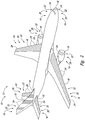
- Fig. 2 illustrates several possible locations for active superhydrophobic surface structures 22 on a particular type of vehicle 12, an aircraft.
- the body 16 may include, and/or may be, an aerodynamic component and/or an airfoil that has a leading edge 18 (e.g., the front of the wings, etc.).
- the active superhydrophobic surface structure 22 may be proximate to, and/or include, the leading edge 18 of the airfoil and/or the aerodynamic component (e.g., the controlled region 24 may or may not include the leading edge 18, and the controlled region 24 may be proximate to the leading edge 18). Additionally or alternatively, the active superhydrophobic surface structure 22 may be oriented relative to the leading edge 18.
- the active superhydrophobic surface structure 22 may be elongated with an elongated direction oriented parallel, substantially parallel, oblique, perpendicular, and/or substantially perpendicular to the leading edge.
- ice tends to form near the leading edge.
- active superhydrophobic surface structures 22 including, abutting, and/or proximate to the leading edge 18 may prevent ice accumulation and/or assist ice removal.
- the outermost (or topmost) component of the active superhydrophobic surface structure 22 is the elastomeric covering 28, i.e., the elastomeric covering 28 defines at least a portion of the exposed surface 20.
- the elastomeric covering 28 is configured to distort under the influence of the MEMS actuator(s) 30 of the controlled group 26.
- motion of the MEMS actuator(s) 30 of the controlled group 26 affects the surface shape of the controlled region 24 of the exposed surface 20.
- the elastomeric covering 28, without any distortions induced by the MEMS actuator(s) 30, may be superhydrophobic, hydrophobic, hydrophilic, oleophobic, oleophilic, and/or not superhydrophobic.
- the undistorted exposed surface 20 of the elastomeric covering 28 is the ordinary state 44 of the controlled region 24 of the exposed surface 20 and the distorted exposed surface 20 of the elastomeric covering 28 is the superhydrophobic state 42 of the controlled region 24 of the exposed surface 20.
- the elastomeric covering 28 may be configured such that the undistorted exposed surface 20 of the elastomeric covering 28 is the superhydrophobic state 42 and the distorted exposed surface 20 of the elastomeric covering 28 is the ordinary state 44.
- the elastomeric covering 28 covers the controlled group 26, directly or indirectly contacting at least a portion of each of the MEMS actuators 30 of the controlled group 26.
- the elastomeric covering 28 may encase one or more (e.g., all) of the MEMS actuators 30 of the controlled group 26.
- the elastomeric covering 28 may include, and/or may consist essentially of, silicone, polydimethylsiloxane, polyurethane, fluoropolymer, and/or pigment.
- the elastomeric covering 28, and the active superhydrophobic surface structure 22 as a whole, may be optically transparent, absorbing, scattering, and/or pigmented.
- the elastomeric covering 28 and/or the active superhydrophobic surface structure 22 may be applied to and/or may be integral with transparent structures (e.g., transparent bodies 16) and/or opaque structures (e.g., opaque bodies 16, paint, and/or exterior coatings).
- transparent structures e.g., transparent bodies 16
- opaque structures e.g., opaque bodies 16, paint, and/or exterior coatings.
- the elastomeric covering 28 may protect the controlled group 26 and/or the underlying structure from damage and/or environmental contamination.
- Active superhydrophobic surface structures 22 and/or bodies 16 may be layered and/or laminated structures, optionally including one or more layers 36.
- active superhydrophobic surface structures 22 and/or bodies 16 may include, and/or may be, a laminate composite material such as a fiber-reinforced composite.
- Each layer 36 of the layered and/or laminated structure may independently include carbon fiber, aramid fiber, glass fiber, resin, epoxy, and/or elastomer.
- the topmost layer 36 is the elastomeric covering 28.
- the MEMS actuator(s) 30 may be arranged in a layer 36, e.g., a layer 36 of the elastomeric covering 28.
- Electronic components such as MEMS actuator(s) 30
- electrical systems e.g., a controller 62, as described further herein
- the active superhydrophobic surface structure 22 may be a surface layer 36 of the body 16, with the body 16 otherwise providing support for the active superhydrophobic surface structure 22 and/or the apparatus 10.
- the controlled group 26 of MEMS actuator(s) 30 is configured to selectively transition the controlled region 24 between the superhydrophobic state 42 and the ordinary state 44 by actuation of the MEMS actuator(s) 30.
- the actuation of the MEMS actuator(s) 30 distorts the exposed surface 20 of the elastomeric covering 28, causing a local change in texture (e.g., surface roughness) corresponding to the change between the superhydrophobic state 42 and the ordinary state 44.
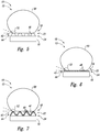
- Each MEMS actuator 30 may have an activated state 32 and a deactivated state 34 (as schematically represented in the respective examples of Figs. 3 and 4 ).
- the MEMS actuator 30 deforms, deflects, and/or modifies a portion of the controlled region 24.
- the MEMS actuator 30 does not deform, deflect, or modify the controlled region 24 and, thus, the controlled region 24 is unaffected and/or unmodified by the MEMS actuator 30 in the deactivated state 34.
- the activated state 32 distorts the controlled region 24 to form a more textured controlled region 24 (e.g., the superhydrophobic state 42) and the deactivated state 34 puts the controlled region 24 into a smoother state (e.g., the ordinary state 44), the activated state 32 and the deactivated state 34 may have the opposite effects. That is, the unaffected and/or unmodified shape of the controlled region 24 (i.e., the shape of the exposed surface 20 of the elastomeric covering 28) may be relatively textured (hence, the MEMS actuator(s) 30 may be configured to reduce the texture upon activation) or relatively smooth (hence, the MEMS actuator(s) 30 may be configured to reduce the smoothness and increase the texture upon activation).
- the superhydrophobic state 42 of the controlled region 24 may correspond to all MEMS actuator(s) 30 of the controlled group 26 being in the activated state 32 (as shown in Fig. 3 ) or all being in the deactivated state 34.
- the related ordinary state 44 of the controlled region 24 may correspond to all MEMS actuator(s) 30 of the controlled group 26 being in the opposite (deactivated/activated) state (i.e., all being in the deactivated state 34, as shown in Fig. 4 , or all being in the activated state 32).
- controlled regions 24 have a micro-textured surface ( Fig. 5 ), a nano-textured surface ( Fig. 6 ), and/or a hierarchically textured surface ( Fig. 7 ).
- Micro-textured, nano-textured, and hierarchically textured also may be called micro-roughness, nano-roughness, and hierarchical roughness, respectively.
- the textured surfaces may be configured to increase the hydrophobicity of the controlled region 24 (relative to the same material and surface without the textured surface).
- the controlled region 24 in the superhydrophobic state 42 and/or in the ordinary state 44 may be micro-textured, nano-textured, and/or hierarchically textured.
- the superhydrophobic state 42 and the ordinary state 44 are distinguished by more texture in the superhydrophobic state 42 than the ordinary state 44.
- the ordinary state 44 lacked any small-scale texture
- the superhydrophobic state 42 may be micro-textured, nano-textured, and/or hierarchically textured.
- the ordinary state 44 may be nano-textured and the superhydrophobic state 42 may be micro-textured and/or hierarchically textured.
- the ordinary state 44 may be micro-textured and the superhydrophobic state 42 may be nano-textured and/or hierarchically textured.
- Micro-textured surfaces include a plurality of microprotrusions 46 (micron-scaled features).
- the MEMS actuator(s) 30 may be configured to selectively form the microprotrusions 46 and/or to selectively eliminate the microprotrusions 46.
- Microprotrusions 46 are configured to trap gas between a water drop 50 on the controlled region 24 and the controlled region 24.
- Microprotrusions 46 may include, and/or may be, columns, posts, pins, filaments, ridges, ribs, cones, pyramids, lobes, projections, and/or convexities.
- microprotrusions 46 may include interconnecting webs, membranes, and/or other structures connecting two or more microprotrusions 46 together.
- Microprotrusions 46 may be arrayed across the controlled region 24 (in a regular, irregular, and/or random arrangement) and may be spaced apart from one another with an average spacing of less than 100 ⁇ m (micron), less than 30 ⁇ m, less than 10 ⁇ m, less than 3 ⁇ m, less than 1 ⁇ m, greater than 1 ⁇ m, greater than 3 ⁇ m, greater than 10 ⁇ m, and/or greater than 30 ⁇ m.
- the spaces between the microprotrusions 46 may be referred to as microcavities.
- Microprotrusions 46 may have an average height of less than 100 ⁇ m, less than 30 ⁇ m, less than 10 ⁇ m, less than 3 ⁇ m, less than 1 ⁇ m, greater than 1 ⁇ m, greater than 3 ⁇ m, greater than 10 ⁇ m, and/or greater than 30 ⁇ m.
- Nano-textured surfaces include a plurality of nanoprotrusions 48 (nanometer-scaled features). Nanoprotrusions 48 are smaller than microprotrusions 46 and may be much smaller than microprotrusions 46.
- the MEMS actuator(s) 30 may be configured to selectively form the nanoprotrusions 48 and/or to selectively eliminate the nanoprotrusions 48.
- Nanoprotrusions 48 are configured to trap gas between a water drop 50 on the controlled region 24 and the controlled region 24.
- Nanoprotrusions 48 may include, and/or may be, asperities, columns, posts, pins, filaments, ridges, ribs, clusters, particles, lobes, projections, and/or convexities.
- nanoprotrusions 46 may include interconnecting webs, membranes, and/or other structures connecting two or more nanoprotrusions 48 together.
- Nanoprotrusions 48 may be arrayed across the controlled region 24 (in a regular, irregular, and/or random arrangement) and may be spaced apart from one another with an average spacing of less than 1,000 nm, less than 300 nm, less than 100 nm, less than 30 nm, less than 10 nm, less than 3 nm, greater than 1 nm, greater than 3 nm, greater than 10 nm, greater than 30 nm, and/or greater than 100 nm.
- the spaces between the nanoprotrusions 46 may be referred to as nanocavities.
- Nanoprotrusions 48 may have an average height of less than 1,000 nm, less than 300 nm, less than 100 nm, less than 30 nm, less than 10 nm, less than 3 nm, greater than 1 nm, greater than 3 nm, greater than 10 nm, greater than 30 nm, and/or greater than 100 nm.
- Hierarchically textured surfaces include a plurality of microprotrusions 46 and a plurality of nanoprotrusions 48 interspersed with one another.
- nanoprotrusions 48 may be on top of and/or project from microprotrusions 46.
- the MEMS actuator(s) 30 may be configured to selectively form and/or to selectively eliminate microprotrusions 46 and/or nanoprotrusions 48.
- the MEMS actuator(s) 30 may selectively form and/or eliminate at least one of the microprotrusions 46 and/or at least one of the nanoprotrusions 48.
- MEMS actuators 30 are small electro-mechanical devices that typically are formed using microfabrication and/or nanofabrication techniques. MEMS actuators 30 also may be called microsystems actuators, micromachined actuators, nano-electro-mechanical system (NEMS) actuators, nanosystems actuators, and/or nanomachined actuators.
- the physical dimensions of MEMS actuators 30 generally are between about one micron and several millimeters, though MEMS actuators may include larger or smaller structures, e.g., structures as small as one atom.
- MEMS actuators 30 include a moving element configured to change shape upon application of an electrical signal.
- MEMS actuators 30 include electrostatic actuators, thermal actuators, piezoelectric actuators, electromagnetic actuators, thermopneumatic actuators, thin film bulk acoustic resonators, and bent beam thermal actuators.
- MEMS actuators 30 typically are fabricated on and/or from semiconductor substrates and may include a piezoelectric material, a shape memory material, and/or a bimetallic material. Further descriptions of MEMS actuators suitable to be a MEMS actuator 30 may be found in Girbau, D., et al., "RF MEMS Switches Based on the Buckle-beam Thermal Actuator," 33rd European Microwave Conf. Proc. 2, pp. 651-654 (2003 ) and Wang.
- a single MEMS actuator 30 may be configured to selectively form and/or eliminate one or more microprotrusions 46 and/or nanoprotrusions 48.
- the MEMS actuators 30 may be arrayed under the controlled region 24 (in a regular, irregular, and/or random arrangement) and/or arranged in a layer 36 (e.g., within the elastomeric covering 28).
- MEMS actuators 30 may be spaced apart from one another with an average spacing of less than 100 ⁇ m, less than 30 ⁇ m, less than 10 ⁇ m, less than 3 ⁇ m, less than 1 ⁇ m, less than 0.3 ⁇ m, less than 0.1 ⁇ m, greater than 0.1 ⁇ m, greater than 0.3 ⁇ m, greater than 1 ⁇ m, greater than 3 ⁇ m, greater than 10 ⁇ m, and/or greater than 30 ⁇ m.
- MEMS actuators 30 may be disposed under the controlled region 24 at a surface density of at least 100, at least 1,000, at least 10,000, at least 100,000, at least 1,000,000, at most 10,000,000, at most 1,000,000, at most 100,000, at most 10,000, and/or at most 1,000 per square centimeter.
- Active superhydrophobic surface structures 22 may comprise a plurality of vibration generators 64 that are configured to selectively vibrate the controlled region 24 and/or to selectively impart a sonic shock into the controlled region 24.
- Vibration generators 64 may impart sonic energy (e.g., infrasonic, acoustic, and/or ultrasonic energy) into the controlled region 24. Additionally or alternatively, vibration generators 64 may impart a sonic shock that propagates to the controlled region 24.
- a sonic shock is a shock wave (e.g., induced by a large impulse of sonic energy) that emanates from the vibration generator 64. Shock waves travel faster than the speed of sound in the medium (e.g., the material(s) of the active superhydrophobic surface structure 22, the layer(s) 36, and/or the elastomeric covering 28).
- Vibration generators 64 generally are configured to shed ice, water, oil, dirt, and/or other contaminants from at least the controlled region 24 of the exposed surface 20.
- Vibration generators 64 may include, and/or may be, a sonic generator, a sonic transducer, an ultrasonic generator, an ultrasonic transducer, an acoustic resonator, and/or a piezoelectric actuator. Additionally or alternatively, MEMS actuators 30 may include one or more vibration generators 64.
- Vibration generators 64 may be arrayed under the controlled region 24 (in a regular, irregular, and/or random arrangement) and/or arranged in a layer 36 (e.g., within the elastomeric covering 28, interspersed in a layer with the MEMS actuator(s) 30, and/or in a layer below a layer of MEMS actuator(s) 30).
- Active superhydrophobic surface structures 22 may comprise one or more heaters 66 that are configured to selectively heat the controlled region 24.
- Heaters 66 generally are configured to melt ice that may form on the controlled region 24 and/or to raise the temperature of the controlled region 24 to and/or above the local freezing point and/or dew point.
- MEMS actuators 30 and/or vibration generators 64 may include heaters 66.
- Heaters 66 may be arrayed under the controlled region 24 (in a regular, irregular, and/or random arrangement) and/or arranged in a layer 36 (e.g., within the elastomeric covering 28, interspersed in a layer with the MEMS actuator(s) 30, interspersed in a layer with the vibration generators 64, in a layer below a layer of MEMS actuator(s) 30, and/or in a layer below or above a layer of vibration generators 64).
- Apparatus 10 may comprise a controller 62 and/or one or more sensors 60.
- the sensors 60 are configured to measure, to detect, and/or to determine properties related to the apparatus 10, the body 16, the exposed surface 20, the active superhydrophobic surface structure 22, the controlled region 24, the controlled group 26, one or more MEMS actuators 30, and/or the environment near (e.g., proximate to) any one or more of the foregoing.
- the property may include, and/or may be, temperature, speed of the apparatus 10 and/or one of its components, wind speed, wind direction, orientation of the apparatus 10 and/or one of its components (e.g., orientation of the exposed surface 20), angle of attack (angle of an object relative to the air velocity), humidity, and/or pressure.
- the sensor(s) 60 may be configured, collectively and/or individually, to measure, to detect, and/or to determine condensation conditions, icing conditions, environmental conditions, and/or exposed surface conditions.
- the controller 62 is configured to control the active superhydrophobic surface structure 22 based on input (e.g., information, signal(s), etc.) from the sensor(s) 60.
- the controller 62 does not necessarily require sensors 60.
- the controller 62 may control the active superhydrophobic surface structure 22 based upon a predetermined pattern and/or external input.
- the controller 62 may be configured to control the active superhydrophobic surface structure 22 in a feedback loop with the sensor(s) 60.
- Controllers 62 may include, and/or may be, a computer, a programmable logic controller, a power controller, and/or a power supply.
- Controllers 62 may be configured to receive input from at least one sensor 60 (i.e., to receive the output of at least one sensor 60). Where the apparatus 10 includes avionics, the controller 62 may be configured to communicate with the avionics, for example, receiving input from the avionics (e.g., the avionics includes a sensor 60) and/or sending output to the avionics.
- Controllers 62 are configured to transition the controlled region 24 of exposed surface 20 between the superhydrophobic state 42 and the ordinary state 44 by transitioning the MEMS actuator(s) 30 of the controlled group 26 between the activated state 32 and the deactivated state 34 (e.g., by activating and/or deactivating the MEMS actuator(s) 30). Controllers 62 may be configured to transition the controlled region 24 from the ordinary state 44 to the superhydrophobic state 42 based upon a detection of condensation conditions, a detection of icing conditions, a detection of environmental conditions, a detection of exposed surface conditions, a forecast of condensation conditions, a forecast of icing conditions, a forecast of environmental conditions, and/or a forecast of exposed surface conditions.
- controllers 62 may control optional vibration generators 64 and/or optional heaters 66.
- the controller 62 may be configured to activate the vibration generator 64 and/or the heater 66 based upon a detection of condensation conditions, a detection of icing conditions, a detection of environmental conditions, a detection of exposed surface conditions, a forecast of condensation conditions, a forecast of icing conditions, a forecast of environmental conditions, and/or a forecast of exposed surface conditions.
- Active superhydrophobic surface structures 22 may be utilized to minimize water accumulation, to prevent water accumulation, to remove water accumulation, to remove ice accumulation, to prevent ice accumulation, to remove contamination, and/or to prevent contamination on the exposed surface 20.
- Methods of use may comprise activating the controlled region 24 by transitioning the controlled region 24 to the superhydrophobic state 42 from the ordinary state 44, and deactivating the controlled region 24 by transitioning the controlled region 24 to the ordinary state 44 from the superhydrophobic state 42.
- the apparatus 10 includes a sensor 60
- the activating may include activating the controlled region 24 based upon a sensor output and/or the deactivating may include deactivating the controlled region 24 based upon a sensor output.
- the activating and/or the deactivating may include activating and/or deactivating, respectively, based upon a property of the apparatus 10, the body 16, the exposed surface 20, the active superhydrophobic surface structure 22, the controlled region 24, the controlled group 26, one or more MEMS actuators 30, and/or the environment near (e.g., proximate to) any one or more of the foregoing.
- Methods may further comprise determining the presence of a condensation condition, an icing condition, an environmental condition, an exposed surface condition, a forecasted condensation condition, a forecasted icing condition, a forecasted environmental condition, and/or a forecasted exposed surface condition, and then transitioning the controlled region 24 to the superhydrophobic state 42.
- Controllers 62 may be configured and/or programmed to perform any of the foregoing methods.
- the terms “adapted” and “configured” mean that the element, component, or other subject matter is designed and/or intended to perform a given function.
- the use of the terms “adapted” and “configured” should not be construed to mean that a given element, component, or other subject matter is simply “capable of” performing a given function but that the element, component, and/or other subject matter is specifically selected, created, implemented, utilized, programmed, and/or designed for the purpose of performing the function.
- elements, components, and/or other recited subject matter that is recited as being adapted to perform a particular function may additionally or alternatively be described as being configured to perform that function, and vice versa.
- the phrase, "for example,” the phrase, “as an example,” and/or simply the term “example,” when used with reference to one or more components, features, details, structures, embodiments, and/or methods according to the present disclosure, are intended to convey that the described component, feature, detail, structure, embodiment, and/or method is an illustrative, non-exclusive example of components, features, details, structures, embodiments, and/or methods according to the present disclosure.
Landscapes
- Engineering & Computer Science (AREA)
- Aviation & Aerospace Engineering (AREA)
- Microelectronics & Electronic Packaging (AREA)
- Computer Hardware Design (AREA)
- Health & Medical Sciences (AREA)
- General Health & Medical Sciences (AREA)
- Manufacturing & Machinery (AREA)
- Toxicology (AREA)
- Life Sciences & Earth Sciences (AREA)
- Molecular Biology (AREA)
- Mechanical Engineering (AREA)
- Micromachines (AREA)
- Laminated Bodies (AREA)
Claims (14)
- Aktive superhydrophobe Oberflächenstruktur (22), die umfasst:eine äußere elastomere Abdeckung (28), die eine exponierte Oberfläche (20) definiert,eine gesteuerte Gruppe (26) von einem Aktuator oder mehreren Aktuatoren (30) aus einem mikroelektromechanischen System - MEMS- , die zumindest durch die äußere elastomere Abdeckung (28) abgedeckt ist,einen gesteuerten Bereich (24) der exponierten Oberfläche (20), welcher der gesteuerten Gruppe (26) entspricht, undeine Vielzahl von Vibrationsgeneratoren (64),wobei der gesteuerte Bereich (24) einen superhydrophoben Zustand (42), in dem der gesteuerte Bereich (24) texturiert ist, und einen normalen Zustand (44) besitzt, in dem der gesteuerte Bereich (24) glatt ist, wobei die aktive superhydrophobe Oberflächenstruktur dazu eingerichtet ist, dass ein selektiver Übergang des gesteuerten Bereichs (24) zwischen dem superhydrophoben Zustand (42) und dem normalen Zustand (44) durch Aktivieren des einen MEMS-Aktuators oder der mehreren MEMS-Aktuatoren (30) der gesteuerten Gruppe (26) erfolgt,dadurch gekennzeichnet, dass die Vibrationsgeneratoren (64) einen Ultraschall-Generator und/oder einen Ultraschall-Wandler umfassen und dazu eingerichtet sind, Eis, Wasser, Öl und/oder Schmutz von dem gesteuerten Bereich (24) abzuweisen, wobei der gesteuerte Bereich (24) in dem superhydrophoben Zustand (42) superhydrophob und oleophob ist und wobei der gesteuerte Bereich (24) in dem normalen Zustand (44) hydrophob ist.
- Aktive superhydrophobe Oberflächenstruktur (22) von Anspruch 1, bei welcher der gesteuerte Bereich (24) in dem superhydrophoben Zustand (42) eisabweisend ist.
- Aktive superhydrophobe Oberflächenstruktur (22) von Anspruch 1, bei der ein Kontaktwinkel (52) von Wasser mit dem gesteuerten Bereich (24) in dem superhydrophoben Zustand (42) größer ist als ein Kontaktwinkel (52) von Wasser mit dem gesteuerten Bereich (24) in dem normalen Zustand (44).
- Aktive superhydrophobe Oberflächenstruktur (22) von Anspruch 1, bei der in dem superhydrophoben Zustand (42) jeder MEMS-Aktuator (30) der gesteuerten Gruppe (26) aktiviert ist, um einen Teil des gesteuerten Bereichs (24) zu verformen, und bei der in dem normalen Zustand (44) des gesteuerten Bereichs (24) jeder MEMS-Aktuator (30) der gesteuerten Gruppe (26) deaktiviert ist und der gesteuerte Bereich (24) durch die gesteuerte Gruppe (26) von MEMS-Aktuatoren (30) unbeeinflusst ist.
- Aktive superhydrophobe Oberflächenstruktur (22) von Anspruch 1, bei welcher der gesteuerte Bereich (24) in dem superhydrophoben Zustand (42) eine Vielzahl vom Mikrovorsprüngen (46) enthält und bei welcher der eine MEMS-Aktuator oder die mehreren MEMS-Aktuatoren (30) dazu eingerichtet sind, die Mikrovorsprünge (46) selektiv zu erzeugen.
- Aktive superhydrophobe Oberflächenstruktur (22) von Anspruch 1, bei welcher der gesteuerte Bereich (24) in dem superhydrophoben Zustand (42) und/oder dem normalen Zustand (44) eine Vielzahl von Nanovorsprüngen (48) enthält und bei welcher der eine MEMS-Aktuator oder die mehreren MEMS-Aktuatoren (30) dazu eingerichtet sind, die Nanovorsprünge (48) selektiv zu erzeugen.
- Aktive superhydrophobe Oberflächenstruktur (22) von Anspruch 1, bei der die Vielzahl von Vibrationsgeneratoren (64) dazu eingerichtet sind, (a) den gesteuerten Bereich (24) selektiv in Vibration zu versetzen und/oder (b) den gesteuerten Bereich (24) mit einer akustischen Stoßwelle zu beaufschlagen.
- Aktive superhydrophobe Oberflächenstruktur (22) von Anspruch 1, die ferner eine Heizeinrichtung (66) enthält, die dazu eingerichtet ist, den gesteuerten Bereich (24) selektiv zu erwärmen.
- Aktive superhydrophobe Oberflächenstruktur (22) von Anspruch 1, wobei die aktive superhydrophobe Oberflächenstruktur (22) eine Vielzahl von gesteuerten Gruppen (26) sowie eine Vielzahl von gesteuerten Bereichen (24) enthält, die den gesteuerten Gruppen (26) entsprechen.
- Vorrichtung (10), die umfasst:einen Körper (16) undeine aktive superhydrophobe Oberflächenstruktur (22) nach einem der Ansprüche 1 bis 9,wobei der Körper (16) die aktive superhydrophobe Oberflächenstruktur (22) enthält.
- Vorrichtung (10) von Anspruch 10, bei welcher der Körper (16) eine aerodynamische Komponente beinhaltet, die eine Vorderkante (18) aufweist, und bei der die aktive superhydrophobe Oberflächenstruktur (22) nahe an der Vorderkante (18) liegt.
- Vorrichtung (10) von Anspruch 10, die ferner eine Steuereinrichtung (62) und einen Sensor oder mehrere Sensoren (60) enthält und
bei der mindestens einer der Sensoren (60) dazu eingerichtet ist, eine gemessene Eigenschaft zu messen, wobei die gemessene Eigenschaft eine Eigenschaft der exponierten Oberfläche (20) und/oder eine Eigenschaft der Vorrichtung (10) und/oder eine Eigenschaft einer Umgebung in der Nähe der Vorrichtung (10) ist, wobei die gemessene Eigenschaft mindestens eine der folgenden Eigenschaften einschließt: Temperatur, Geschwindigkeit der Vorrichtung, Windgeschwindigkeit, Windrichtung, Orientierung der Vorrichtung, Orientierung der exponierten Oberfläche, Anstellwinkel, Feuchte und Druck. - Vorrichtung von Anspruch 10, wobei die Vorrichtung ein Flugzeug ist, wobei das Flugzeug umfasst:eine aerodynamische Komponente mit einer Vorderkante (18),eine Steuereinrichtung (62),einen Sensor oder mehrere Sensoren (60) unddie aktive superhydrophobe Oberflächenstruktur (22),wobei die aktive superhydrophobe Oberflächenstruktur (22) nahe an der Vorderkante (18) liegt, undwobei die Steuereinrichtung (62) dazu eingerichtet ist, den gesteuerten Bereich (24) der aktiven superhydrophoben Oberflächenstruktur (22) auf der Basis zumindest von Information von den Sensoren (60) in einem Regelkreis mit Rückführung zu steuern.
- Vorrichtung von Anspruch 13, bei der die Steuereinrichtung (62) dazu eingerichtet ist, einen Übergang des gesteuerten Bereichs (24) zwischen dem superhydrophoben Zustand (42) und dem normalen Zustand (44) durchzuführen durch Aktivieren des einen MEMS-Aktuators oder der mehreren MEMS-Aktuatoren (30) der gesteuerten Gruppe (26), um in den superhydrophoben Zustand (42) überzuführen, und durch Deaktivieren des einen MEMS-Aktuators oder der mehreren MEMS-Aktuatoren (30) der gesteuerten Gruppe (26), um in den normalen Zustand (44) überzuführen.
Applications Claiming Priority (1)
| Application Number | Priority Date | Filing Date | Title |
|---|---|---|---|
| US14/522,255 US20160114883A1 (en) | 2014-10-23 | 2014-10-23 | Actively-controlled superhydrophobic surfaces |
Publications (2)
| Publication Number | Publication Date |
|---|---|
| EP3012187A1 EP3012187A1 (de) | 2016-04-27 |
| EP3012187B1 true EP3012187B1 (de) | 2019-02-13 |
Family
ID=55085435
Family Applications (1)
| Application Number | Title | Priority Date | Filing Date |
|---|---|---|---|
| EP15190974.4A Active EP3012187B1 (de) | 2014-10-23 | 2015-10-22 | Aktiv gesteuerte superhydrophobe oberflächen |
Country Status (3)
| Country | Link |
|---|---|
| US (2) | US20160114883A1 (de) |
| EP (1) | EP3012187B1 (de) |
| CN (1) | CN105539817B (de) |
Cited By (1)
| Publication number | Priority date | Publication date | Assignee | Title |
|---|---|---|---|---|
| FR3147792A1 (fr) * | 2023-04-12 | 2024-10-18 | Safran Aircraft Engines | Partie tournante d’un recepteur de turbomachine munie d’un dispositif d’antigivrage |
Families Citing this family (34)
| Publication number | Priority date | Publication date | Assignee | Title |
|---|---|---|---|---|
| FR3004165B1 (fr) * | 2013-04-09 | 2015-03-27 | Aircelle Sa | Element d'aeronef necessitant un traitement contre le givre |
| US10500370B2 (en) * | 2015-09-02 | 2019-12-10 | Syracuse University | Antifouling urinary catheters with shape-memory topographic patterns |
| US10118705B2 (en) * | 2016-06-15 | 2018-11-06 | The Boeing Company | Hybrid acoustic and induction-heating systems and methods for impeding formation of ice |
| US10252807B2 (en) * | 2016-07-08 | 2019-04-09 | Goodrich Corporation | Runback control |
| FR3058985B1 (fr) * | 2016-11-21 | 2019-07-19 | Dassault Aviation | Piece d'aeronef destinee a entrer en contact avec une masse d'air situee autour de l'aeronef, aeronef et procede associes |
| CN108394512A (zh) * | 2017-02-06 | 2018-08-14 | 郭志诚 | 介质膜随动技术 |
| US10231061B2 (en) * | 2017-04-28 | 2019-03-12 | Infineon Technologies Ag | Sound transducer with housing and MEMS structure |
| CN107127190B (zh) * | 2017-05-31 | 2023-04-07 | 中国空气动力研究与发展中心低速空气动力研究所 | 超疏水材料和振动除冰相耦合的主被动防冰装置及其方法 |
| US11181545B2 (en) | 2017-08-17 | 2021-11-23 | Rosemount Aerospace Inc. | Angle of attack sensor with thermal enhancement |
| CN107878748B (zh) * | 2017-09-27 | 2019-06-18 | 中国运载火箭技术研究院 | 一种跨介质飞行器壳体结构及飞行器 |
| US10875632B2 (en) | 2017-11-08 | 2020-12-29 | Goodrich Corporation | Ice phobic material to reduce runback ice |
| US10435134B2 (en) * | 2017-12-12 | 2019-10-08 | The Boeing Company | Core structures for composite panels of an aircraft, composite panels and aircraft including the core structures, and methods of manufacturing the composite panels |
| JP6677703B2 (ja) * | 2017-12-21 | 2020-04-08 | 株式会社Subaru | 雷電流制御装置、雷電流制御方法及び航空機 |
| EP4001119B1 (de) * | 2018-01-05 | 2024-06-05 | Rosemount Aerospace Inc. | Merkmale zur vermeidung von eisansammlungen auf beheizten frontplatten |
| EP3527917A1 (de) * | 2018-02-16 | 2019-08-21 | Vestel Elektronik Sanayi ve Ticaret A.S. | Kühlvorrichtung zum abtauen |
| US10877062B2 (en) | 2018-05-09 | 2020-12-29 | Rosemount Aerospace Inc. | Aft-located heated ramp for ice and water management of angle of attack sensors |
| US10928416B2 (en) | 2018-05-09 | 2021-02-23 | Rosemount Aerospace Inc. | Dual heated ramp for ice and water management in angle of attack sensors |
| US11008109B2 (en) | 2018-07-16 | 2021-05-18 | The Boeing Company | Aircraft ice protection systems |
| EP3643618B1 (de) * | 2018-10-26 | 2020-12-02 | LEONARDO S.p.A. | Schaufel für ein schwebefähiges flugzeug und verfahren zur entfernung von eis von der besagten schaufel |
| GB2581974A (en) * | 2019-03-05 | 2020-09-09 | Airbus Operations Ltd | Aerofoil leading edge structures |
| US11162970B2 (en) | 2019-06-17 | 2021-11-02 | Rosemount Aerospace Inc. | Angle of attack sensor |
| US12459870B2 (en) * | 2019-07-31 | 2025-11-04 | Northeastern University | Thermally conductive boron nitride films and multilayered composites containing them |
| CN110510102B (zh) * | 2019-08-16 | 2022-06-17 | 南京航空航天大学 | 一种可贴式自阻加热/超疏水一体化梯度薄膜材料 |
| US20210129997A1 (en) * | 2019-11-05 | 2021-05-06 | Rohr, Inc. | Thermal anti-icing system with microwave system |
| US12060261B2 (en) * | 2019-11-06 | 2024-08-13 | Bvw Holding Ag | Extremal microstructured surfaces |
| US20210179276A1 (en) * | 2019-12-12 | 2021-06-17 | Goodrich Corporation | Ice protection system for rotary blades |
| US11649057B2 (en) | 2019-12-13 | 2023-05-16 | Rosemount Aerospace Inc. | Static plate heating arrangement |
| US12360134B2 (en) | 2020-02-25 | 2025-07-15 | Rosemount Aerospace Inc. | Angle of attack sensor with sloped faceplate |
| EP4074603B1 (de) * | 2021-04-15 | 2025-07-23 | Airbus Defence and Space GmbH | Enteisungssystem, tragflügel und flugzeug mit einem solchen system sowie enteisungsverfahren |
| CN118742400A (zh) * | 2021-12-07 | 2024-10-01 | 3M创新有限公司 | 具有较低刮痕可见度的微结构化表面和制品以及方法 |
| US12296944B2 (en) * | 2022-04-19 | 2025-05-13 | The Texas A&M University System | Systems and methods for producing traveling waves along surfaces exposed to supersonic fluid flows |
| CN116587702A (zh) * | 2023-04-21 | 2023-08-15 | 广州大学 | 一种快速切换超疏水性的气动智能表面结构及其制备方法 |
| US12612166B2 (en) | 2023-06-28 | 2026-04-28 | Airbus Operations Sas | Method for de-icing an aerodynamic wall using at least two different de-icing systems, aircraft equipped with a de-icing device making it possible to implement said method |
| US20250242926A1 (en) * | 2024-01-29 | 2025-07-31 | Goodrich Corporation | Composite aircraft component with embedded piezoelectric ice protection |
Citations (2)
| Publication number | Priority date | Publication date | Assignee | Title |
|---|---|---|---|---|
| US20080054762A1 (en) * | 2004-03-04 | 2008-03-06 | Ludwiczak Damian R | Vibrating debris remover |
| US20100031972A1 (en) * | 2008-05-28 | 2010-02-11 | Fbs, Inc. | Ultrasonic vibration system and method for removing/avoiding unwanted build-up on structures |
Family Cites Families (30)
| Publication number | Priority date | Publication date | Assignee | Title |
|---|---|---|---|---|
| US3416027A (en) * | 1967-03-10 | 1968-12-10 | Mc Donnell Douglas Corp | Radome lightning protection means |
| US4732351A (en) | 1985-03-21 | 1988-03-22 | Larry Bird | Anti-icing and deicing device |
| US5615849A (en) * | 1995-04-14 | 1997-04-01 | Salisbury; Jonathan T. | Microwave deicing and anti-icing system for aircraft |
| US5934617A (en) * | 1997-09-22 | 1999-08-10 | Northcoast Technologies | De-ice and anti-ice system and method for aircraft surfaces |
| DE69935346T2 (de) * | 1998-10-27 | 2007-11-15 | Trustees Of Dartmouth College | Systeme und verfahren zum verändern der klebkraft von eis |
| US7223312B2 (en) * | 2000-09-21 | 2007-05-29 | Integument Technologies, Inc. | Methods and materials for reducing damage from environmental electromagnetic effects |
| PL204021B1 (pl) * | 2001-11-02 | 2009-12-31 | Cnt Spo & Lstrok Ka Z Ogranicz | Powłoka superhydrofobowa |
| US7014143B2 (en) * | 2002-10-11 | 2006-03-21 | The Boeing Company | Aircraft lightning strike protection and grounding technique |
| US6890152B1 (en) | 2003-10-03 | 2005-05-10 | General Electric Company | Deicing device for wind turbine blades |
| US7281318B2 (en) * | 2004-05-19 | 2007-10-16 | The Boeing Company | Method of manufacturing a composite structural member having an integrated electrical circuit |
| US7459197B2 (en) * | 2004-11-30 | 2008-12-02 | Lucent Technologies Inc. | Reversibly adaptive rough micro- and nano-structures |
| US7695767B2 (en) * | 2005-01-06 | 2010-04-13 | The Boeing Company | Self-cleaning superhydrophobic surface |
| US20090011222A1 (en) * | 2006-03-27 | 2009-01-08 | Georgia Tech Research Corporation | Superhydrophobic surface and method for forming same |
| US7678997B2 (en) * | 2006-12-19 | 2010-03-16 | The Boeing Company | Large area circuitry using appliqués |
| US8276851B2 (en) * | 2007-05-10 | 2012-10-02 | California Institute Of Technology | Control of aerodynamic forces by variable wetted surface morphology |
| FR2924685B1 (fr) * | 2007-12-11 | 2010-03-19 | Airbus France | Systeme parafoudre et aeronef comportant un tel systeme. |
| CN102387915A (zh) * | 2009-02-17 | 2012-03-21 | 伊利诺伊大学评议会 | 柔性微结构超疏水材料 |
| WO2011020876A2 (en) * | 2009-08-19 | 2011-02-24 | Vestas Wind Systems A/S | A wind turbine component having an exposed surface made of a hydrophobic material |
| CN101704410A (zh) * | 2009-12-03 | 2010-05-12 | 上海交通大学 | 用于飞机防冰除冰的纳米超疏水表面及其制备方法 |
| EP2386750A1 (de) | 2010-05-12 | 2011-11-16 | Siemens Aktiengesellschaft | Enteisung und/oder Eisschutz für eine Windturbinenkomponente mittels Vibration eines piezoelektrischen Materials |
| US9303322B2 (en) * | 2010-05-24 | 2016-04-05 | Integran Technologies Inc. | Metallic articles with hydrophobic surfaces |
| US8691104B2 (en) * | 2011-01-14 | 2014-04-08 | California Institute Of Technology | Nanotextured surfaces and related methods, systems, and uses |
| US20120276334A1 (en) * | 2011-02-23 | 2012-11-01 | Massachusetts Institute Of Technology | Surfaces with Controllable Wetting and Adhesion |
| KR20120113532A (ko) | 2011-04-05 | 2012-10-15 | 삼성전자주식회사 | 초소수성 구조물 |
| EP2718101A4 (de) * | 2011-06-08 | 2015-12-02 | Univ Virginia Patent Found | Superhydrophobe nanokompositbeschichtungen |
| WO2014011222A1 (en) * | 2012-07-13 | 2014-01-16 | Massachusetts Institute Of Technology | Thin films with micro-topologies prepared by sequential wrinkling |
| US9339853B2 (en) * | 2012-12-04 | 2016-05-17 | The Boeing Company | Surface materials for decontamination with decontaminants |
| US9422954B2 (en) * | 2012-12-05 | 2016-08-23 | Rensselaer Polytechnic Institute | Piezoelectric driven oscillating surface |
| US9637658B2 (en) * | 2013-06-24 | 2017-05-02 | The Boeing Company | Coatings, coating compositions, and methods of delaying ice formation |
| US9400557B2 (en) * | 2014-06-25 | 2016-07-26 | Intel Corporation | Multimodal haptic effect system |
-
2014
- 2014-10-23 US US14/522,255 patent/US20160114883A1/en not_active Abandoned
-
2015
- 2015-10-10 CN CN201510650636.5A patent/CN105539817B/zh active Active
- 2015-10-22 EP EP15190974.4A patent/EP3012187B1/de active Active
-
2019
- 2019-07-10 US US16/508,082 patent/US11447237B2/en active Active
Patent Citations (2)
| Publication number | Priority date | Publication date | Assignee | Title |
|---|---|---|---|---|
| US20080054762A1 (en) * | 2004-03-04 | 2008-03-06 | Ludwiczak Damian R | Vibrating debris remover |
| US20100031972A1 (en) * | 2008-05-28 | 2010-02-11 | Fbs, Inc. | Ultrasonic vibration system and method for removing/avoiding unwanted build-up on structures |
Cited By (2)
| Publication number | Priority date | Publication date | Assignee | Title |
|---|---|---|---|---|
| FR3147792A1 (fr) * | 2023-04-12 | 2024-10-18 | Safran Aircraft Engines | Partie tournante d’un recepteur de turbomachine munie d’un dispositif d’antigivrage |
| WO2024213850A3 (fr) * | 2023-04-12 | 2025-01-09 | Safran Aircraft Engines | Partie tournante d'un recepteur de turbomachine munie d'un dispositif d'antigivrage |
Also Published As
| Publication number | Publication date |
|---|---|
| US11447237B2 (en) | 2022-09-20 |
| US20190329872A1 (en) | 2019-10-31 |
| CN105539817A (zh) | 2016-05-04 |
| EP3012187A1 (de) | 2016-04-27 |
| US20160114883A1 (en) | 2016-04-28 |
| CN105539817B (zh) | 2019-09-13 |
Similar Documents
| Publication | Publication Date | Title |
|---|---|---|
| EP3012187B1 (de) | Aktiv gesteuerte superhydrophobe oberflächen | |
| EP2740210B1 (de) | Verfahren und vorrichtung zur hemmung der bildung von und/oder entfernung von eis von flugzeugkomponenten | |
| Tian et al. | Passive anti-icing performances of the same superhydrophobic surfaces under static freezing, dynamic supercooled-droplet impinging, and icing wind tunnel tests | |
| EP2915747B1 (de) | Systeme und Verfahren zur passiven Enteisung | |
| RU2602266C2 (ru) | Устройство и способ устранения обледенения и/или предотвращения образования льда и профильное тело и летательный аппарат с таким устройством | |
| CA2771393C (en) | Structurally designed aerodynamic riblets | |
| Palacios et al. | Ultrasonic de-icing of wind-tunnel impact icing | |
| EP2535267B1 (de) | System und Verfahren zur Reduzierung von Viskoser Kraft zwischen einer Flüssigkeit und einer Oberfläche | |
| US10822097B2 (en) | Ice formation detection and removal system for an aerial vehicle and method | |
| CA2804556C (en) | Ice protection for aircraft using electroactive polymer surfaces | |
| Munday et al. | Active control of separation on a wing with conformal camber | |
| US12091160B2 (en) | Actively controlled surfaces | |
| EP3643618B1 (de) | Schaufel für ein schwebefähiges flugzeug und verfahren zur entfernung von eis von der besagten schaufel | |
| Ong et al. | Advances in Hybrid Icing and Frosting Protection Strategies for Optics, Lens, and Photonics in Cold Environments Using Thin‐Film Acoustic Waves | |
| EP4074603B1 (de) | Enteisungssystem, tragflügel und flugzeug mit einem solchen system sowie enteisungsverfahren | |
| Strobl et al. | Feasibility study of a hybrid ice protection system based on passive removal of residual ice | |
| Maio et al. | On the use of smart on-board systems for aircraft ice removal | |
| Abudaram et al. | Wind tunnel testing of load-alleviating membrane wings at low reynolds numbers | |
| Matthias et al. | Development of a vibration-based deicing system for aircraft wings | |
| Wang et al. | Review of exploration of aircraft de/anti-icing mechanism and airborne application of superhydrophobic materials | |
| Hamed Nohbaradaran | Development of a thermally sprayed electrothermal antiicing system for inflight ice mitigation | |
| Grishaev et al. | A Criterion for Periodic Ice Shedding to Prolong UAV Flights | |
| Munday et al. | 39th AIAA Aerospace Sciences Meeting and Exhibit January 8–11, 2001/Reno, NV |
Legal Events
| Date | Code | Title | Description |
|---|---|---|---|
| PUAI | Public reference made under article 153(3) epc to a published international application that has entered the european phase |
Free format text: ORIGINAL CODE: 0009012 |
|
| 17P | Request for examination filed |
Effective date: 20151022 |
|
| AK | Designated contracting states |
Kind code of ref document: A1 Designated state(s): AL AT BE BG CH CY CZ DE DK EE ES FI FR GB GR HR HU IE IS IT LI LT LU LV MC MK MT NL NO PL PT RO RS SE SI SK SM TR |
|
| AX | Request for extension of the european patent |
Extension state: BA ME |
|
| STAA | Information on the status of an ep patent application or granted ep patent |
Free format text: STATUS: EXAMINATION IS IN PROGRESS |
|
| 17Q | First examination report despatched |
Effective date: 20170216 |
|
| REG | Reference to a national code |
Ref country code: DE Ref legal event code: R079 Ref document number: 602015024551 Country of ref document: DE Free format text: PREVIOUS MAIN CLASS: B64C0021100000 Ipc: B08B0017060000 |
|
| GRAP | Despatch of communication of intention to grant a patent |
Free format text: ORIGINAL CODE: EPIDOSNIGR1 |
|
| STAA | Information on the status of an ep patent application or granted ep patent |
Free format text: STATUS: GRANT OF PATENT IS INTENDED |
|
| RIC1 | Information provided on ipc code assigned before grant |
Ipc: B08B 3/00 20060101ALI20180305BHEP Ipc: B81C 1/00 20060101ALI20180305BHEP Ipc: B64D 15/00 20060101ALI20180305BHEP Ipc: B08B 17/06 20060101AFI20180305BHEP Ipc: B64C 21/10 20060101ALI20180305BHEP Ipc: B64D 15/16 20060101ALI20180305BHEP Ipc: H02G 13/00 20060101ALI20180305BHEP Ipc: B64D 15/12 20060101ALI20180305BHEP Ipc: B81B 3/00 20060101ALI20180305BHEP |
|
| INTG | Intention to grant announced |
Effective date: 20180410 |
|
| GRAJ | Information related to disapproval of communication of intention to grant by the applicant or resumption of examination proceedings by the epo deleted |
Free format text: ORIGINAL CODE: EPIDOSDIGR1 |
|
| STAA | Information on the status of an ep patent application or granted ep patent |
Free format text: STATUS: EXAMINATION IS IN PROGRESS |
|
| GRAP | Despatch of communication of intention to grant a patent |
Free format text: ORIGINAL CODE: EPIDOSNIGR1 |
|
| STAA | Information on the status of an ep patent application or granted ep patent |
Free format text: STATUS: GRANT OF PATENT IS INTENDED |
|
| INTC | Intention to grant announced (deleted) | ||
| INTG | Intention to grant announced |
Effective date: 20180821 |
|
| GRAS | Grant fee paid |
Free format text: ORIGINAL CODE: EPIDOSNIGR3 |
|
| GRAA | (expected) grant |
Free format text: ORIGINAL CODE: 0009210 |
|
| STAA | Information on the status of an ep patent application or granted ep patent |
Free format text: STATUS: THE PATENT HAS BEEN GRANTED |
|
| AK | Designated contracting states |
Kind code of ref document: B1 Designated state(s): AL AT BE BG CH CY CZ DE DK EE ES FI FR GB GR HR HU IE IS IT LI LT LU LV MC MK MT NL NO PL PT RO RS SE SI SK SM TR |
|
| REG | Reference to a national code |
Ref country code: GB Ref legal event code: FG4D |
|
| REG | Reference to a national code |
Ref country code: CH Ref legal event code: EP Ref country code: AT Ref legal event code: REF Ref document number: 1095904 Country of ref document: AT Kind code of ref document: T Effective date: 20190215 |
|
| REG | Reference to a national code |
Ref country code: IE Ref legal event code: FG4D |
|
| REG | Reference to a national code |
Ref country code: DE Ref legal event code: R096 Ref document number: 602015024551 Country of ref document: DE |
|
| REG | Reference to a national code |
Ref country code: LT Ref legal event code: MG4D |
|
| REG | Reference to a national code |
Ref country code: NL Ref legal event code: MP Effective date: 20190213 |
|
| PG25 | Lapsed in a contracting state [announced via postgrant information from national office to epo] |
Ref country code: PT Free format text: LAPSE BECAUSE OF FAILURE TO SUBMIT A TRANSLATION OF THE DESCRIPTION OR TO PAY THE FEE WITHIN THE PRESCRIBED TIME-LIMIT Effective date: 20190613 Ref country code: SE Free format text: LAPSE BECAUSE OF FAILURE TO SUBMIT A TRANSLATION OF THE DESCRIPTION OR TO PAY THE FEE WITHIN THE PRESCRIBED TIME-LIMIT Effective date: 20190213 Ref country code: NO Free format text: LAPSE BECAUSE OF FAILURE TO SUBMIT A TRANSLATION OF THE DESCRIPTION OR TO PAY THE FEE WITHIN THE PRESCRIBED TIME-LIMIT Effective date: 20190513 Ref country code: FI Free format text: LAPSE BECAUSE OF FAILURE TO SUBMIT A TRANSLATION OF THE DESCRIPTION OR TO PAY THE FEE WITHIN THE PRESCRIBED TIME-LIMIT Effective date: 20190213 Ref country code: LT Free format text: LAPSE BECAUSE OF FAILURE TO SUBMIT A TRANSLATION OF THE DESCRIPTION OR TO PAY THE FEE WITHIN THE PRESCRIBED TIME-LIMIT Effective date: 20190213 Ref country code: NL Free format text: LAPSE BECAUSE OF FAILURE TO SUBMIT A TRANSLATION OF THE DESCRIPTION OR TO PAY THE FEE WITHIN THE PRESCRIBED TIME-LIMIT Effective date: 20190213 |
|
| PG25 | Lapsed in a contracting state [announced via postgrant information from national office to epo] |
Ref country code: BG Free format text: LAPSE BECAUSE OF FAILURE TO SUBMIT A TRANSLATION OF THE DESCRIPTION OR TO PAY THE FEE WITHIN THE PRESCRIBED TIME-LIMIT Effective date: 20190513 Ref country code: GR Free format text: LAPSE BECAUSE OF FAILURE TO SUBMIT A TRANSLATION OF THE DESCRIPTION OR TO PAY THE FEE WITHIN THE PRESCRIBED TIME-LIMIT Effective date: 20190514 Ref country code: RS Free format text: LAPSE BECAUSE OF FAILURE TO SUBMIT A TRANSLATION OF THE DESCRIPTION OR TO PAY THE FEE WITHIN THE PRESCRIBED TIME-LIMIT Effective date: 20190213 Ref country code: HR Free format text: LAPSE BECAUSE OF FAILURE TO SUBMIT A TRANSLATION OF THE DESCRIPTION OR TO PAY THE FEE WITHIN THE PRESCRIBED TIME-LIMIT Effective date: 20190213 Ref country code: LV Free format text: LAPSE BECAUSE OF FAILURE TO SUBMIT A TRANSLATION OF THE DESCRIPTION OR TO PAY THE FEE WITHIN THE PRESCRIBED TIME-LIMIT Effective date: 20190213 Ref country code: IS Free format text: LAPSE BECAUSE OF FAILURE TO SUBMIT A TRANSLATION OF THE DESCRIPTION OR TO PAY THE FEE WITHIN THE PRESCRIBED TIME-LIMIT Effective date: 20190613 |
|
| REG | Reference to a national code |
Ref country code: AT Ref legal event code: MK05 Ref document number: 1095904 Country of ref document: AT Kind code of ref document: T Effective date: 20190213 |
|
| PG25 | Lapsed in a contracting state [announced via postgrant information from national office to epo] |
Ref country code: SK Free format text: LAPSE BECAUSE OF FAILURE TO SUBMIT A TRANSLATION OF THE DESCRIPTION OR TO PAY THE FEE WITHIN THE PRESCRIBED TIME-LIMIT Effective date: 20190213 Ref country code: RO Free format text: LAPSE BECAUSE OF FAILURE TO SUBMIT A TRANSLATION OF THE DESCRIPTION OR TO PAY THE FEE WITHIN THE PRESCRIBED TIME-LIMIT Effective date: 20190213 Ref country code: IT Free format text: LAPSE BECAUSE OF FAILURE TO SUBMIT A TRANSLATION OF THE DESCRIPTION OR TO PAY THE FEE WITHIN THE PRESCRIBED TIME-LIMIT Effective date: 20190213 Ref country code: EE Free format text: LAPSE BECAUSE OF FAILURE TO SUBMIT A TRANSLATION OF THE DESCRIPTION OR TO PAY THE FEE WITHIN THE PRESCRIBED TIME-LIMIT Effective date: 20190213 Ref country code: AL Free format text: LAPSE BECAUSE OF FAILURE TO SUBMIT A TRANSLATION OF THE DESCRIPTION OR TO PAY THE FEE WITHIN THE PRESCRIBED TIME-LIMIT Effective date: 20190213 Ref country code: DK Free format text: LAPSE BECAUSE OF FAILURE TO SUBMIT A TRANSLATION OF THE DESCRIPTION OR TO PAY THE FEE WITHIN THE PRESCRIBED TIME-LIMIT Effective date: 20190213 Ref country code: CZ Free format text: LAPSE BECAUSE OF FAILURE TO SUBMIT A TRANSLATION OF THE DESCRIPTION OR TO PAY THE FEE WITHIN THE PRESCRIBED TIME-LIMIT Effective date: 20190213 Ref country code: ES Free format text: LAPSE BECAUSE OF FAILURE TO SUBMIT A TRANSLATION OF THE DESCRIPTION OR TO PAY THE FEE WITHIN THE PRESCRIBED TIME-LIMIT Effective date: 20190213 |
|
| REG | Reference to a national code |
Ref country code: DE Ref legal event code: R097 Ref document number: 602015024551 Country of ref document: DE |
|
| PG25 | Lapsed in a contracting state [announced via postgrant information from national office to epo] |
Ref country code: SM Free format text: LAPSE BECAUSE OF FAILURE TO SUBMIT A TRANSLATION OF THE DESCRIPTION OR TO PAY THE FEE WITHIN THE PRESCRIBED TIME-LIMIT Effective date: 20190213 Ref country code: PL Free format text: LAPSE BECAUSE OF FAILURE TO SUBMIT A TRANSLATION OF THE DESCRIPTION OR TO PAY THE FEE WITHIN THE PRESCRIBED TIME-LIMIT Effective date: 20190213 |
|
| PLBE | No opposition filed within time limit |
Free format text: ORIGINAL CODE: 0009261 |
|
| STAA | Information on the status of an ep patent application or granted ep patent |
Free format text: STATUS: NO OPPOSITION FILED WITHIN TIME LIMIT |
|
| PG25 | Lapsed in a contracting state [announced via postgrant information from national office to epo] |
Ref country code: AT Free format text: LAPSE BECAUSE OF FAILURE TO SUBMIT A TRANSLATION OF THE DESCRIPTION OR TO PAY THE FEE WITHIN THE PRESCRIBED TIME-LIMIT Effective date: 20190213 |
|
| REG | Reference to a national code |
Ref country code: DE Ref legal event code: R082 Ref document number: 602015024551 Country of ref document: DE Representative=s name: MAIER, LL.M., MICHAEL C., DE Ref country code: DE Ref legal event code: R082 Ref document number: 602015024551 Country of ref document: DE Representative=s name: BOULT WADE TENNANT LLP, DE |
|
| 26N | No opposition filed |
Effective date: 20191114 |
|
| REG | Reference to a national code |
Ref country code: DE Ref legal event code: R082 Ref document number: 602015024551 Country of ref document: DE Representative=s name: BOULT WADE TENNANT LLP, DE |
|
| PG25 | Lapsed in a contracting state [announced via postgrant information from national office to epo] |
Ref country code: SI Free format text: LAPSE BECAUSE OF FAILURE TO SUBMIT A TRANSLATION OF THE DESCRIPTION OR TO PAY THE FEE WITHIN THE PRESCRIBED TIME-LIMIT Effective date: 20190213 |
|
| PG25 | Lapsed in a contracting state [announced via postgrant information from national office to epo] |
Ref country code: TR Free format text: LAPSE BECAUSE OF FAILURE TO SUBMIT A TRANSLATION OF THE DESCRIPTION OR TO PAY THE FEE WITHIN THE PRESCRIBED TIME-LIMIT Effective date: 20190213 |
|
| PG25 | Lapsed in a contracting state [announced via postgrant information from national office to epo] |
Ref country code: MC Free format text: LAPSE BECAUSE OF FAILURE TO SUBMIT A TRANSLATION OF THE DESCRIPTION OR TO PAY THE FEE WITHIN THE PRESCRIBED TIME-LIMIT Effective date: 20190213 |
|
| REG | Reference to a national code |
Ref country code: CH Ref legal event code: PL |
|
| PG25 | Lapsed in a contracting state [announced via postgrant information from national office to epo] |
Ref country code: LI Free format text: LAPSE BECAUSE OF NON-PAYMENT OF DUE FEES Effective date: 20191031 Ref country code: CH Free format text: LAPSE BECAUSE OF NON-PAYMENT OF DUE FEES Effective date: 20191031 Ref country code: LU Free format text: LAPSE BECAUSE OF NON-PAYMENT OF DUE FEES Effective date: 20191022 |
|
| REG | Reference to a national code |
Ref country code: BE Ref legal event code: MM Effective date: 20191031 |
|
| PG25 | Lapsed in a contracting state [announced via postgrant information from national office to epo] |
Ref country code: BE Free format text: LAPSE BECAUSE OF NON-PAYMENT OF DUE FEES Effective date: 20191031 |
|
| PG25 | Lapsed in a contracting state [announced via postgrant information from national office to epo] |
Ref country code: IE Free format text: LAPSE BECAUSE OF NON-PAYMENT OF DUE FEES Effective date: 20191022 |
|
| PG25 | Lapsed in a contracting state [announced via postgrant information from national office to epo] |
Ref country code: CY Free format text: LAPSE BECAUSE OF FAILURE TO SUBMIT A TRANSLATION OF THE DESCRIPTION OR TO PAY THE FEE WITHIN THE PRESCRIBED TIME-LIMIT Effective date: 20190213 |
|
| PG25 | Lapsed in a contracting state [announced via postgrant information from national office to epo] |
Ref country code: HU Free format text: LAPSE BECAUSE OF FAILURE TO SUBMIT A TRANSLATION OF THE DESCRIPTION OR TO PAY THE FEE WITHIN THE PRESCRIBED TIME-LIMIT; INVALID AB INITIO Effective date: 20151022 Ref country code: MT Free format text: LAPSE BECAUSE OF FAILURE TO SUBMIT A TRANSLATION OF THE DESCRIPTION OR TO PAY THE FEE WITHIN THE PRESCRIBED TIME-LIMIT Effective date: 20190213 |
|
| PG25 | Lapsed in a contracting state [announced via postgrant information from national office to epo] |
Ref country code: MK Free format text: LAPSE BECAUSE OF FAILURE TO SUBMIT A TRANSLATION OF THE DESCRIPTION OR TO PAY THE FEE WITHIN THE PRESCRIBED TIME-LIMIT Effective date: 20190213 |
|
| P01 | Opt-out of the competence of the unified patent court (upc) registered |
Effective date: 20230516 |
|
| PGFP | Annual fee paid to national office [announced via postgrant information from national office to epo] |
Ref country code: DE Payment date: 20251029 Year of fee payment: 11 |
|
| PGFP | Annual fee paid to national office [announced via postgrant information from national office to epo] |
Ref country code: GB Payment date: 20251027 Year of fee payment: 11 |
|
| PGFP | Annual fee paid to national office [announced via postgrant information from national office to epo] |
Ref country code: FR Payment date: 20251027 Year of fee payment: 11 |