EP3012425B1 - Urea water suitability determination device - Google Patents
Urea water suitability determination device Download PDFInfo
- Publication number
- EP3012425B1 EP3012425B1 EP14813624.5A EP14813624A EP3012425B1 EP 3012425 B1 EP3012425 B1 EP 3012425B1 EP 14813624 A EP14813624 A EP 14813624A EP 3012425 B1 EP3012425 B1 EP 3012425B1
- Authority
- EP
- European Patent Office
- Prior art keywords
- urea water
- temperature
- determination
- suitability
- detection targets
- Prior art date
- Legal status (The legal status is an assumption and is not a legal conclusion. Google has not performed a legal analysis and makes no representation as to the accuracy of the status listed.)
- Not-in-force
Links
Images

Classifications
-
- G—PHYSICS
- G01—MEASURING; TESTING
- G01N—INVESTIGATING OR ANALYSING MATERIALS BY DETERMINING THEIR CHEMICAL OR PHYSICAL PROPERTIES
- G01N33/00—Investigating or analysing materials by specific methods not covered by groups G01N1/00 - G01N31/00
- G01N33/18—Water
- G01N33/1826—Organic contamination in water
-
- F—MECHANICAL ENGINEERING; LIGHTING; HEATING; WEAPONS; BLASTING
- F01—MACHINES OR ENGINES IN GENERAL; ENGINE PLANTS IN GENERAL; STEAM ENGINES
- F01N—GAS-FLOW SILENCERS OR EXHAUST APPARATUS FOR MACHINES OR ENGINES IN GENERAL; GAS-FLOW SILENCERS OR EXHAUST APPARATUS FOR INTERNAL-COMBUSTION ENGINES
- F01N11/00—Monitoring or diagnostic devices for exhaust-gas treatment apparatus
- F01N11/002—Monitoring or diagnostic devices for exhaust-gas treatment apparatus the diagnostic devices measuring or estimating temperature or pressure in, or downstream of the exhaust apparatus
-
- F—MECHANICAL ENGINEERING; LIGHTING; HEATING; WEAPONS; BLASTING
- F01—MACHINES OR ENGINES IN GENERAL; ENGINE PLANTS IN GENERAL; STEAM ENGINES
- F01N—GAS-FLOW SILENCERS OR EXHAUST APPARATUS FOR MACHINES OR ENGINES IN GENERAL; GAS-FLOW SILENCERS OR EXHAUST APPARATUS FOR INTERNAL-COMBUSTION ENGINES
- F01N3/00—Exhaust or silencing apparatus having means for purifying, rendering innocuous, or otherwise treating exhaust
- F01N3/08—Exhaust or silencing apparatus having means for purifying, rendering innocuous, or otherwise treating exhaust for rendering innocuous
- F01N3/10—Exhaust or silencing apparatus having means for purifying, rendering innocuous, or otherwise treating exhaust for rendering innocuous by thermal or catalytic conversion of noxious components of exhaust
- F01N3/18—Exhaust or silencing apparatus having means for purifying, rendering innocuous, or otherwise treating exhaust for rendering innocuous by thermal or catalytic conversion of noxious components of exhaust characterised by methods of operation; Control
- F01N3/20—Exhaust or silencing apparatus having means for purifying, rendering innocuous, or otherwise treating exhaust for rendering innocuous by thermal or catalytic conversion of noxious components of exhaust characterised by methods of operation; Control specially adapted for catalytic conversion
- F01N3/206—Adding periodically or continuously substances to exhaust gases for promoting purification, e.g. catalytic material in liquid form, NOx reducing agents
- F01N3/2066—Selective catalytic reduction [SCR]
-
- G—PHYSICS
- G01—MEASURING; TESTING
- G01N—INVESTIGATING OR ANALYSING MATERIALS BY DETERMINING THEIR CHEMICAL OR PHYSICAL PROPERTIES
- G01N25/00—Investigating or analyzing materials by the use of thermal means
-
- G—PHYSICS
- G01—MEASURING; TESTING
- G01N—INVESTIGATING OR ANALYSING MATERIALS BY DETERMINING THEIR CHEMICAL OR PHYSICAL PROPERTIES
- G01N29/00—Investigating or analysing materials by the use of ultrasonic, sonic or infrasonic waves; Visualisation of the interior of objects by transmitting ultrasonic or sonic waves through the object
- G01N29/02—Analysing fluids
- G01N29/024—Analysing fluids by measuring propagation velocity or propagation time of acoustic waves
-
- F—MECHANICAL ENGINEERING; LIGHTING; HEATING; WEAPONS; BLASTING
- F01—MACHINES OR ENGINES IN GENERAL; ENGINE PLANTS IN GENERAL; STEAM ENGINES
- F01N—GAS-FLOW SILENCERS OR EXHAUST APPARATUS FOR MACHINES OR ENGINES IN GENERAL; GAS-FLOW SILENCERS OR EXHAUST APPARATUS FOR INTERNAL-COMBUSTION ENGINES
- F01N2550/00—Monitoring or diagnosing the deterioration of exhaust systems
- F01N2550/05—Systems for adding substances into exhaust
-
- F—MECHANICAL ENGINEERING; LIGHTING; HEATING; WEAPONS; BLASTING
- F01—MACHINES OR ENGINES IN GENERAL; ENGINE PLANTS IN GENERAL; STEAM ENGINES
- F01N—GAS-FLOW SILENCERS OR EXHAUST APPARATUS FOR MACHINES OR ENGINES IN GENERAL; GAS-FLOW SILENCERS OR EXHAUST APPARATUS FOR INTERNAL-COMBUSTION ENGINES
- F01N2610/00—Adding substances to exhaust gases
- F01N2610/02—Adding substances to exhaust gases the substance being ammonia or urea
-
- F—MECHANICAL ENGINEERING; LIGHTING; HEATING; WEAPONS; BLASTING
- F01—MACHINES OR ENGINES IN GENERAL; ENGINE PLANTS IN GENERAL; STEAM ENGINES
- F01N—GAS-FLOW SILENCERS OR EXHAUST APPARATUS FOR MACHINES OR ENGINES IN GENERAL; GAS-FLOW SILENCERS OR EXHAUST APPARATUS FOR INTERNAL-COMBUSTION ENGINES
- F01N2900/00—Details of electrical control or of the monitoring of the exhaust gas treating apparatus
- F01N2900/06—Parameters used for exhaust control or diagnosing
- F01N2900/08—Parameters used for exhaust control or diagnosing said parameters being related to the engine
-
- F—MECHANICAL ENGINEERING; LIGHTING; HEATING; WEAPONS; BLASTING
- F01—MACHINES OR ENGINES IN GENERAL; ENGINE PLANTS IN GENERAL; STEAM ENGINES
- F01N—GAS-FLOW SILENCERS OR EXHAUST APPARATUS FOR MACHINES OR ENGINES IN GENERAL; GAS-FLOW SILENCERS OR EXHAUST APPARATUS FOR INTERNAL-COMBUSTION ENGINES
- F01N2900/00—Details of electrical control or of the monitoring of the exhaust gas treating apparatus
- F01N2900/06—Parameters used for exhaust control or diagnosing
- F01N2900/18—Parameters used for exhaust control or diagnosing said parameters being related to the system for adding a substance into the exhaust
- F01N2900/1806—Properties of reducing agent or dosing system
- F01N2900/1811—Temperature
-
- F—MECHANICAL ENGINEERING; LIGHTING; HEATING; WEAPONS; BLASTING
- F01—MACHINES OR ENGINES IN GENERAL; ENGINE PLANTS IN GENERAL; STEAM ENGINES
- F01N—GAS-FLOW SILENCERS OR EXHAUST APPARATUS FOR MACHINES OR ENGINES IN GENERAL; GAS-FLOW SILENCERS OR EXHAUST APPARATUS FOR INTERNAL-COMBUSTION ENGINES
- F01N2900/00—Details of electrical control or of the monitoring of the exhaust gas treating apparatus
- F01N2900/06—Parameters used for exhaust control or diagnosing
- F01N2900/18—Parameters used for exhaust control or diagnosing said parameters being related to the system for adding a substance into the exhaust
- F01N2900/1806—Properties of reducing agent or dosing system
- F01N2900/1818—Concentration of the reducing agent
-
- G—PHYSICS
- G01—MEASURING; TESTING
- G01N—INVESTIGATING OR ANALYSING MATERIALS BY DETERMINING THEIR CHEMICAL OR PHYSICAL PROPERTIES
- G01N2291/00—Indexing codes associated with group G01N29/00
- G01N2291/01—Indexing codes associated with the measuring variable
- G01N2291/011—Velocity or travel time
-
- Y—GENERAL TAGGING OF NEW TECHNOLOGICAL DEVELOPMENTS; GENERAL TAGGING OF CROSS-SECTIONAL TECHNOLOGIES SPANNING OVER SEVERAL SECTIONS OF THE IPC; TECHNICAL SUBJECTS COVERED BY FORMER USPC CROSS-REFERENCE ART COLLECTIONS [XRACs] AND DIGESTS
- Y02—TECHNOLOGIES OR APPLICATIONS FOR MITIGATION OR ADAPTATION AGAINST CLIMATE CHANGE
- Y02A—TECHNOLOGIES FOR ADAPTATION TO CLIMATE CHANGE
- Y02A50/00—TECHNOLOGIES FOR ADAPTATION TO CLIMATE CHANGE in human health protection, e.g. against extreme weather
- Y02A50/20—Air quality improvement or preservation, e.g. vehicle emission control or emission reduction by using catalytic converters
-
- Y—GENERAL TAGGING OF NEW TECHNOLOGICAL DEVELOPMENTS; GENERAL TAGGING OF CROSS-SECTIONAL TECHNOLOGIES SPANNING OVER SEVERAL SECTIONS OF THE IPC; TECHNICAL SUBJECTS COVERED BY FORMER USPC CROSS-REFERENCE ART COLLECTIONS [XRACs] AND DIGESTS
- Y02—TECHNOLOGIES OR APPLICATIONS FOR MITIGATION OR ADAPTATION AGAINST CLIMATE CHANGE
- Y02T—CLIMATE CHANGE MITIGATION TECHNOLOGIES RELATED TO TRANSPORTATION
- Y02T10/00—Road transport of goods or passengers
- Y02T10/10—Internal combustion engine [ICE] based vehicles
- Y02T10/12—Improving ICE efficiencies
-
- Y—GENERAL TAGGING OF NEW TECHNOLOGICAL DEVELOPMENTS; GENERAL TAGGING OF CROSS-SECTIONAL TECHNOLOGIES SPANNING OVER SEVERAL SECTIONS OF THE IPC; TECHNICAL SUBJECTS COVERED BY FORMER USPC CROSS-REFERENCE ART COLLECTIONS [XRACs] AND DIGESTS
- Y02—TECHNOLOGIES OR APPLICATIONS FOR MITIGATION OR ADAPTATION AGAINST CLIMATE CHANGE
- Y02T—CLIMATE CHANGE MITIGATION TECHNOLOGIES RELATED TO TRANSPORTATION
- Y02T10/00—Road transport of goods or passengers
- Y02T10/10—Internal combustion engine [ICE] based vehicles
- Y02T10/40—Engine management systems
Definitions
- the techniques of the present disclosure relate to a urea water suitability determination device that determines suitability of urea water.
- a conventional exhaust gas purifier is known to purify nitrogen oxide (hereinafter, refer to as NOx) in exhaust gas.
- the exhaust gas purifier includes a urea water supply system, which supplies urea water to the exhaust gas, and a selective reduction catalyst, into which the exhaust gas supplied with the urea water flows.
- a urea water supply system which supplies urea water to the exhaust gas
- a selective reduction catalyst into which the exhaust gas supplied with the urea water flows.
- an abnormality occurs in the quality of the urea water.
- Variation in the quality of the urea water changes the amount of urea water necessary for obtaining desired purification performance in the exhaust gas purifier.
- Patent Document 1 causes a sensor to detect the concentration of the urea water in the tank, and suitability of the urea water is determined based on the detected value. The driver is warned when an abnormality occurs in the quality of the urea water.
- An object of the techniques of the present disclosure is to provide a urea water suitability determination device that improves the reliability of a determination result in the suitability of urea water.
- One aspect of the present disclosure is to provide a urea water suitability determination device comprising: a concentration detecting section (35), which detects a concentration (C) of urea water and outputs the detected value; a determining section (44), which determines whether the urea water is suitable by using the detected value output from the concentration detecting section (35); and a temperature detecting section (29, 35, 45), which detects temperatures (Tex, Tu, Tw) of a plurality of detection targets at different locations in a vehicle, wherein the detection targets have temperatures that are different from one another during operation of an engine (10), the determining section (44) is adapted to: calculate a temperature difference between a temperature of a particular detection target and a temperature of another detection target among the detection targets; and when a determination start condition is satisfied, start determining whether the urea water is suitable, the determination start condition includes that the temperature difference is within a reference range, and the reference range is defined as a range of temperature differences in which it is determined that the urea water is in a qui
- a urea water suitability determination device according to a first part of the invention will now be described with reference to Figs. 1 and 2 .
- a diesel engine 10 (hereinafter, referred to simply as the engine 10) includes an exhaust gas purifier 20 for purifying exhaust gas, which is arranged in an exhaust passage 12. Exhaust gas that has flowed into the exhaust gas purifier 20 flows into a first stage oxidation catalyst 22.
- the first stage oxidation catalyst 22 is a diesel oxidation catalyst (DOC), which oxidizes and transforms hydrocarbons (HC), carbon monoxide (CO), and nitric monoxide (NO) contained in the exhaust gas into water, carbon dioxide, nitrogen dioxide, and the like.
- DOC diesel oxidation catalyst
- the first stage oxidation catalyst 22 includes, for example, a support, which is formed of alumina, silica, zeolite, and metal, such as platinum and palladium, and metal oxide, which are supported by the support.
- the DPF 24 is formed of ceramics and a metal porous body to capture particulate matter (PM) in the exhaust gas.
- PM particulate matter
- a regeneration process of the DPF 24 the temperature of the exhaust gas flowing into the DPF 24 is raised. This is realized, for example, by supplying combustion gas from a burner (not shown) to a portion of the exhaust passage 12 that is located upstream of the first stage oxidation catalyst 22, or by supplying fuel from a fuel injection valve (not shown) to the portion.
- An exhaust gas temperature sensor 29 is arranged downstream of the DPF 24 and upstream of a selective reduction catalyst 36, which will be described later.
- the exhaust gas temperature sensor 29 serves as a temperature detecting section for detecting a temperature of the exhaust passage 12 as a detection target.
- the exhaust gas temperature sensor 29 detects a temperature in a portion of the exhaust passage 12 that is located downstream of the DPF 24 at a predetermined control period.
- the exhaust gas temperature sensor 29 outputs, to the ECU 44, signal indicative of an exhaust gas temperature Tex, which is a detected value.
- An electronically controlled injector 30 is arranged downstream of the exhaust gas temperature sensor 29 and supplies urea water, which is a reducing agent, to the exhaust passage 12.
- a pressure pump 34 pumps urea water stored in a tank 32 to the injector 30.
- a relief valve (not shown) is built in the pressure pump 34 so that the urea water in the tank 32 is pumped to the injector 30 at a predetermined pressure.
- the ECU 44 controls opening and closing of the injector 30.
- the urea water supplied to the exhaust gas is hydrolyzed to ammonia with heat of the exhaust gas.
- a urea water quality sensor 35 (hereinafter, simply referred to as the "sensor 35") is arranged in the tank 32.
- the sensor 35 detects information of the urea water in the tank 32.
- the sensor 35 outputs, to the ECU 44, a signal indicative of a urea water temperature Tu, which is a temperature of the urea water, and a signal indicative of a liquid level indicative of the remaining amount of the urea water.
- the sensor 35 also measures a propagation velocity Vus of an ultrasonic wave in the urea water.
- the sensor 35 calculates a urea water concentration C by correcting a value obtained from the measured propagation velocity Vus based on the urea water temperature Tu.
- the sensor 35 outputs a signal indicative of the urea water concentration C to the ECU 44.
- the sensor 35 functions as a concentration detecting section for detecting the urea water concentration C and functions as a temperature detecting section for detecting the urea water temperature Tu, which is a temperature of the urea water as a detection target.
- the injector 30, the tank 32, the pressure pump 34, the sensor 35, and the urea water form a urea water supply system.
- a selective reduction catalyst 36 is arranged downstream of the injector 30.
- the selective reduction catalyst 36 performs selective catalytic reduction to reduce NOx using ammonia.
- the selective reduction catalyst 36 includes, for example, a support, which is formed of honeycomb ceramics, and high adsorptive zeolite or zirconia, which is supported by the support. NOx in the exhaust gas reacts with ammonia in catalysis of the selective reduction catalyst 36 and is reduced into nitrogen and water.
- the second stage oxidation catalyst 40 is an ammonia slip catalyst (ASC), which dissolves ammonia unconsumed in the reduction reaction of the selective reduction catalyst 36.
- ASC ammonia slip catalyst
- the second stage oxidation catalyst 40 includes, for example, a support, which includes alumina, silica, and zeolite, metal, such as platinum and palladium, and metal oxide, which are supported by the support.
- the ECU 44 is a microcomputer, which includes a CPU, a RAM, a ROM, and the like. As described above, the ECU 44 receives signals indicative of the urea water concentration C, the urea water temperature Tu, and the exhaust gas temperature Tex. In addition to those, the ECU 44 receives a signal indicative of a coolant temperature Tw from a coolant temperature sensor 45 at a predetermined control period.
- the coolant temperature sensor 45 serves as a temperature detecting section for detecting a temperature of coolant that cools the engine 10 as a detection target.
- the urea water temperature Tu, the exhaust gas temperature Tex, and the coolant temperature Tw are different from one another, and the detectable highest temperatures are also different. In other words, each of the detection targets for the temperature detecting section has a different temperature range during operation of the engine 10.
- the ECU 44 receives signals from various types of sensors at a predetermined control period.
- the signals include a signal from a brake sensor 47, a signal from a gear position sensor 48, and a signal from a vehicle speed sensor 49.
- the signal from the brake sensor 47 is indicative of brake information Binf, which shows the operation state of the brake.
- the signal from the gear position sensor 48 is indicative of gear information Ginf, which shows the gear position.
- the signal from the vehicle speed sensor 49 is indicative of a vehicle speed V of the vehicle, which is equipped with the engine 10.
- the brake sensor 47, the gear position sensor 48, and the vehicle speed sensor 49 function as a parking information detecting section.
- the ECU 44 executes various computations and processes based on information received from each of the sensors, and a control program and various types of data, which are stored in the ROM in advance.
- the ECU 44 executes a urea water supply process by controlling opening and closing of the injector 30.
- the ECU 44 as a suitability determination device executes a determination process that determines whether the urea water in the tank 32 is suitable, i.e., determines the suitability of the urea water. If the urea water is a regular product, which satisfies a desired quality, the urea water is determined as suitable. In the determination process, the ECU 44 functions as a determining section that determines the suitability of the urea water. When obtaining abnormality as a determination result, the ECU 44 activates an alarm 50 to notify the driver of the determination result.
- the ECU 44 acquires various types of information at the initial step S11.
- Such information includes the exhaust gas temperature Tex, the urea water temperature Tu, the coolant temperature Tw, the brake information Binf, the gear information Ginf, and the vehicle speed V.
- the ECU 44 calculates a temperature difference between a particular detection target and another detection target among a plurality of detection targets.
- the ECU 44 acquires a maximum value ⁇ Tmax from the temperature differences.
- the ECU 44 determines whether the maximum value ⁇ Tma is within a reference range, which is less than or equal to a threshold ⁇ Tt.
- the ECU 44 selects any two temperatures among the exhaust gas temperature Tex, the urea water temperature Tu, and the coolant temperature Tw as targets for the temperature difference calculation.
- the ECU 44 calculates the temperature difference between the selected two temperatures.
- the ECU 44 acquires the greatest value among the temperature differences as the maximum value ⁇ Tmax.
- the ECU 44 determines whether the maximum value ⁇ Tma is within the reference range, which is less than or equal to the threshold ⁇ Tt.
- the threshold ⁇ Tt has the maximum value ⁇ Tmax, e.g., 15°C when the urea water is in a quiescent state, i.e., a state without vibrations, bubbles and the like after sufficient time has passed from the previous stop of the engine 10.
- the threshold ⁇ Tt is a preset value in various types of data, which is determined through various types of experiments and simulations.
- ) between the coolant temperature Tw and the urea water temperature Tu have different thresholds, with which it is determined that the urea water is in the quiescent state. In other words, any combinations of two targets are selected, and each of the combinations has a different threshold. With the threshold, it is determined that the urea water is in the quiescent state.
- the threshold ⁇ Tt has the greatest value among the thresholds of the temperature differences.
- a determination start condition is defined as that the maximum value ⁇ Tmax is less than or equal to the threshold ⁇ Tt.
- step S12 determines that the urea water is not in the quiescent state and finishes a series of processes.
- the maximum value ⁇ Tmax is less than or equal to the threshold ⁇ Tt (step S12: YES)
- the ECU 44 acquires a determination concentration C1 from the sensor 35 (step S13).
- the determination concentration C1 is a concentration for determining the suitability of the urea water.
- the ECU 44 determines whether the vehicle speed V, which is acquired at step 11, is less than or equal to the threshold Vt, e.g. 0 km/h, (step S14).
- step S14 determines whether the brake information Binf acquired at step 11 is OFF (step S15).
- step S15 When the brake information Binf is OFF (step S15: YES), i.e., when the brake is not being operated, the ECU 44 determines whether the gear information Ginf acquired at step S11 is N, i.e., whether the gear position is neutral, i.e., whether the engine and the transmission are disconnected (step S16).
- a stopped condition is defined as a state in which the vehicle speed V is less than or equal to the threshold Vt (step S14); the brake information Binf is OFF (step S15); and the gear information Ginf is N (step S16).
- the stopped condition is not satisfied.
- the ECU 44 determines that the vehicle is not in the stopped state and finishes the determination process.
- step S17 the ECU 44 determines whether the determination concentration C1 acquired at step S13 is within a normal range (step S17).
- the normal range is greater than or equal to a lower limit Cmin and less than or equal to an upper limit Cmax.
- the determination concentration C1 is within the normal range, it is determined that the urea water is a regular product.
- the lower limit Cmin and the upper limit Cmax are provided in advance in the respective types of data and determined in consideration of measurement error of the sensor 35.
- the ECU 44 includes the determination start condition and the stopped condition as conditions to determine the suitability of the urea water.
- step S17 NO
- the ECU 44 determines that the urea water in the tank 32 is abnormal and activates the alarm 50 (step S19).
- the ECU 44 warns the driver that the urea water in the tank 32 is abnormal, and finishes the series of processes.
- step S17 when the determination concentration C1 is within the normal range (step S17: YES), the ECU 44 determines that the urea water in the tank 32 is normal.
- the ECU 44 newly acquires the same type of information as the information acquired at step S11 (step S18) and moves to step S13.
- the ECU 44 repeats determination of suitability of the urea water until the stopped condition is no longer satisfied or until it is determined that the urea water is abnormal.
- the urea water is in the quiescent state in comparison to a case in which the maximum value ⁇ Tmax exceeds the threshold ⁇ Tt.
- the sensor 35 calculates the determination concentration C1 based on the propagation velocity Vus in the urea water, which is in the quiescent state. This decreases error of the determination concentration C1 relative to the actual concentration of the urea water. Thus, the reliability of the determination concentration C1 is increased, and eventually increases the reliability of the determination result in suitability of the urea water.
- the urea water suitability determination device achieves the advantages listed below.
- a urea water suitability determination device according to a second part of the invention will now be described with reference to Figs. 3 to 5 .
- elements different from the first part will be described in detail, and elements with similar functions to those in the first part will not be described in detail by assigning like reference characters.
- an exhaust gas purifier 20 includes a branch passage 52 divided from the coolant passage, through which the coolant passes to cool the engine 10.
- a portion of the branch passage 52 travels in the tank 32.
- a valve 54 is arranged in the branch passage 52, and opens or closes the branch passage 52. The opening and closing of the valve 54 is controlled by the ECU 44. When the valve 54 is in an open state, some of the coolant flows into the branch passage 52. Heat is exchanged between the coolant flowing through the branch passage 52 and the urea water in the tank 32.
- the branch passage 52 functions as a heating section for heating the urea water.
- Fig. 4 is a graph illustrating the relationship between the urea water temperature Tu and the propagation speed Vus as an example of result when a regular product is compared to a counterfeit product.
- a solid line indicates a regular product 56
- a long dashed double-short dashed line indicates a counterfeit product 58.
- the propagation speeds Vus in the regular product and the counterfeit product are the same at a urea water temperature Tu3.
- it is impossible that the propagation speeds Vus in the regular product and the counterfeit product are the same at every urea water temperature Tu.
- the suitability of the urea water is determined at two different urea water temperatures Tu.
- the ECU 44 executes a determination process, which will now be described with reference to Fig. 5 .
- the determination process is executed every time the ignition of the vehicle is turned ON.
- the ECU 44 at the initial step S21 acquires various types of information, which includes an exhaust gas temperature Tex, a urea water temperature Tu1, a coolant temperature Tw, brake information Binf, gear information Ginf, and a vehicle speed V.
- the ECU 44 determines whether the determination start condition is satisfied based on the various types of information.
- step S22: NO When the determination start condition is not satisfied (step S22: NO), the ECU 44 finishes the determination process. In contrast, when the determination start condition is satisfied (step S22: YES), the ECU 44 acquires the determination concentration C1 from the sensor 35 (step S23).
- step S24 the ECU 44 determines whether the stopped condition is satisfied based on the various types of information acquired at step S21.
- the stopped condition is not satisfied (step S24: NO)
- the ECU 44 finishes the determination process.
- the stopped condition is satisfied (step S24: YES)
- the ECU 44 determines whether the determination concentration C1, which is acquired at step S23, is within the normal range (step S25). The process at this step S25 is the first determining opportunity.
- step S25 YES
- the ECU 44 opens the valve 54 at step S26 to cause some of the coolant to circulate through the branch passage 52. This heats the urea water in the tank 32 by exchanging heat with the coolant. Such heat exchange between the coolant and the urea water promotes an increase in the temperature of the urea water.
- the ECU 44 acquires a new urea water temperature Tu2 from the sensor 35.
- the ECU 44 determines whether the changing amount ⁇ Tu exceeds a preset amount ⁇ Tut (step S28).
- the propagation speed Vus in the regular product becomes equal to the propagation speed Vus in the counterfeit product at the urea water temperature Tu3. Since the determination concentrations C1 are calculated based on the propagation speeds Vus, the determination concentrations C1 in the regular product also becomes equal to the determination concentrations C1 in the counterfeit product.
- the preset amount ⁇ Tut has a value, e.g., 10°C, that allows determination of whether the urea water is a regular product by using the determination concentration C2 based on the propagation speed Vus at the urea water temperature Tu2 even if the urea water temperature Tu1 is the urea water temperature Tu3. In this case, even if the urea water in the tank 32 is a counterfeit product, it is determined that the determination concentration C2 at the urea water temperature Tu2 certainly deviates from the normal range, which leads to the determination that the urea water is a regular product.
- the preset amount ⁇ Tu has a value provided in advance in the various types of data and is determined based on various experiments and simulations, which are performed in advance. The ECU 44 repeats the processes from step S27 to step S28 until the changing amount ⁇ Tu exceeds the preset amount ⁇ Tut.
- step S28 When the changing amount ⁇ Tu exceeds the preset amount ⁇ Tut (step S28: YES), the ECU 44 acquires a new determination concentration C2 from the sensor 35 (step S29) and determines whether the determination concentration C2 is within the normal range (step S30). The process at this step S30 is a second determining opportunity.
- step S30 When the determination concentration C2 is within the normal range (step S30: YES), the ECU 44 determines that the urea water in the tank 32 is normal. The ECU 44 closes the valve 54 (step S31) and finishes a series of processes. In contrast, when the determination concentration C1 or C2 deviates from the normal range at step S25 or step S30, i.e., at the first and second determination opportunities, the ECU 44 activates the alarm 50 (step S32) and closes the valve 54 (step S31). The ECU 44 then finishes the series of processes.
- the determination concentrations C1 and C2 are calculated at two urea water temperatures Tu1 and Tu2, which differ at least by the preset amount ⁇ Tut. Using the determination concentrations C1 and C2, the suitability of the urea water is determined. When any one of the determination concentrations C1 and C2 deviates from the normal range, it is determined that the urea water in the tank 32 is abnormal. In other words, the suitability of the urea water is determined at two different temperatures. This further increases the reliability of determination results in the suitability of the urea water.
- the urea water suitability determination device achieves the following advantages in addition to the advantages (1) to (6), which are described in the first part of the invention.
- the determination process of the second part may be modified as long as multiple determination opportunities are obtained at different urea water temperatures Tu.
- both of the urea water temperatures Tu1 and Tu2 may be set in advance.
- a third determining opportunity may be set according to the changing amount of the urea water temperature Tu2.
- the start timing of the determination process is not limited to when the ignition is turned ON.
- the determination process may be started after operation of the ignition or when the ignition is turned OFF. Even in the case in which the determination process is started when the ignition is turned OFF, multiple determination opportunities are obtained at different urea water temperatures, while the urea water temperature converges to the ambient temperature.
- the second determining opportunity is set based on the change amount ⁇ Tu.
- the second determining opportunity may be set, for example, based on an amount of elapsed time from the first determining opportunity. The elapsed time may be changed according to a change in an operating state of the engine 10 after the first determining opportunity.
- the heating section for heating the urea water is not limited to the branch passage 52, which is divided from the cooling passage of the engine.
- the heating section may be an electronic device such as a heater or a passage divided from the exhaust passage 12, through which some of the exhaust gas flows.
- the stopped condition includes a condition that allows determining that the vehicle is stopped, the invention may be modified.
- the stopped condition may include only a condition associated with the vehicle speed V among the above three conditions. A new condition other than the three conditions may be added to the stopped condition.
- the stopped condition may be omitted.
- the determination start condition is satisfied when the ignition is turned ON, the suitability of the urea water may be determined.
- an alternative condition may be set such that it is determined that the state of the urea water is maintained in the quiescent state.
- the threshold Vt of the vehicle speed V may be replaced with 5 km/h.
- the suitability of the urea water may be repeatedly determined.
- the ECU 44 may move to the process at step S12 when the process at step S18 in Fig. 2 is finished.
- detection targets of the temperature detecting section are not limited to the above three detection targets, i.e., the urea water, the coolant of the engine 10, and the exhaust passage of the engine 10.
- the detection targets of the temperature detecting section may include any targets having different temperatures on operation of the engine 10 in a space defined by the vehicle.
- the detection targets may be any two of the three detection targets.
- the detection targets may include the ambient temperature, engine oil, and the like.
- the highest temperatures of the detection targets that may be detected during operation of the engine 10 greatly differ.
- the exhaust passage as the detection targets is not limited to a portion of the exhaust passage 12.
- the exhaust passage may be a pipe itself, which forms the exhaust passage 12. In other words, the temperature detecting section may detect the temperature in the pipe of the exhaust passage 12 instead of the temperature in the exhaust passage 12.
- the senor 35 as the concentration detecting section outputs a urea water temperature Tu and a propagation speed Vus to the ECU 44.
- the ECU 44 may calculate the urea water concentration C based on the urea water temperature Tu and the propagation speed Vus.
- the ECU 44 is provided with data that defines a normal range of propagation speeds Vus at each urea water temperature Tu, and the suitability of the urea water may be determined based on the data.
- the threshold may be set for each combination of any two selected detection targets.
- the threshold ⁇ Tt may be set at the smallest value among the thresholds, which are set for each combination.
- the determination concentration C1 may be a concentration in the process at step S11, i.e., immediately before the determination start condition is satisfied.
- the engine is not limited to a diesel engine.
- the engine may be a gasoline engine or natural gas engine.
Landscapes
- Chemical & Material Sciences (AREA)
- Engineering & Computer Science (AREA)
- Health & Medical Sciences (AREA)
- Life Sciences & Earth Sciences (AREA)
- Chemical Kinetics & Catalysis (AREA)
- Physics & Mathematics (AREA)
- Immunology (AREA)
- Pathology (AREA)
- General Physics & Mathematics (AREA)
- General Health & Medical Sciences (AREA)
- Biochemistry (AREA)
- Analytical Chemistry (AREA)
- Mechanical Engineering (AREA)
- General Engineering & Computer Science (AREA)
- Combustion & Propulsion (AREA)
- Food Science & Technology (AREA)
- Medicinal Chemistry (AREA)
- Toxicology (AREA)
- Acoustics & Sound (AREA)
- Exhaust Gas After Treatment (AREA)
- Exhaust Gas Treatment By Means Of Catalyst (AREA)
- Combined Controls Of Internal Combustion Engines (AREA)
Description
- The techniques of the present disclosure relate to a urea water suitability determination device that determines suitability of urea water.
- A conventional exhaust gas purifier is known to purify nitrogen oxide (hereinafter, refer to as NOx) in exhaust gas. The exhaust gas purifier includes a urea water supply system, which supplies urea water to the exhaust gas, and a selective reduction catalyst, into which the exhaust gas supplied with the urea water flows. For example, when water in the urea water is excessively evaporated, or when a tank is filled with fluid that does not meet standards, an abnormality occurs in the quality of the urea water. Variation in the quality of the urea water changes the amount of urea water necessary for obtaining desired purification performance in the exhaust gas purifier. On this account, the technique disclosed in Patent Document 1 causes a sensor to detect the concentration of the urea water in the tank, and suitability of the urea water is determined based on the detected value. The driver is warned when an abnormality occurs in the quality of the urea water.
-
- Patent Document 1: Japanese Laid-Open Patent Publication No.
2002-371831 - Patent document 2:
EP 1 900 915 A , shows a method of evaluating the quality of a reducing agent based on its concentration. - In recent years, it has been desired to further improve the reliability of a determination result in the suitability of urea water based on its concentration.
- An object of the techniques of the present disclosure is to provide a urea water suitability determination device that improves the reliability of a determination result in the suitability of urea water.
- One aspect of the present disclosure is to provide a urea water suitability determination device comprising: a concentration detecting section (35), which detects a concentration (C) of urea water and outputs the detected value; a determining section (44), which determines whether the urea water is suitable by using the detected value output from the concentration detecting section (35); and a temperature detecting section (29, 35, 45), which detects temperatures (Tex, Tu, Tw) of a plurality of detection targets at different locations in a vehicle, wherein the detection targets have temperatures that are different from one another during operation of an engine (10), the determining section (44) is adapted to: calculate a temperature difference between a temperature of a particular detection target and a temperature of another detection target among the detection targets; and when a determination start condition is satisfied, start determining whether the urea water is suitable, the determination start condition includes that the temperature difference is within a reference range, and the reference range is defined as a range of temperature differences in which it is determined that the urea water is in a quiescent state, which is suitable for the determination, the detection targets include the urea water, the concentration detecting section (35) is adapted to detect a concentration (C) of the urea water based on a temperature (Tu) of the urea water and a propagation velocity (Vus) of an ultrasonic wave in the urea water, the determining section (44) is adapted to: determine suitability of the urea water at a first determining opportunity, where the urea water is at a first temperature (Tu1), and determine suitability of the urea water at a second determining opportunity, where the urea water is at a second temperature (Tu2), which is different from the first temperature, the urea water suitability determination device further comprises a heating section (52) for heating the urea water, the determining section (44) is adapted to: when the urea water is determined as suitable at the first determining opportunity, heat the urea water by the heating section (52), determine whether a changing amount (ΔTu) of the urea water temperature from the first temperature (Tu1) exceeds a preset amount (ΔTut), and when the changing amount (ΔTu) exceeds the preset amount (ΔTut), determines suitability of the urea water at the second determining opportunity.
-
-
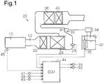
Fig. 1 is a schematic view of an exhaust gas purifier having a urea water suitability determination device according to the invention; -
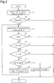
Fig. 2 is a flowchart showing a determination process in the suitability determination device ofFig. 1 ; -
Fig. 3 is a schematic view of an exhaust gas purifier having a urea water suitability determination device according to the invention; -
Fig. 4 is a graph showing one example of result in a comparison between a regular product and a counterfeit product in terms of the relationship between urea water temperature and propagation velocity of ultrasonic waves; and -
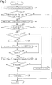
Fig. 5 is a flowchart showing determination processes of the suitability determination device ofFig. 3 . - A urea water suitability determination device according to a first part of the invention will now be described with reference to
Figs. 1 and2 . - As shown in
Fig. 1 , a diesel engine 10 (hereinafter, referred to simply as the engine 10) includes anexhaust gas purifier 20 for purifying exhaust gas, which is arranged in anexhaust passage 12. Exhaust gas that has flowed into theexhaust gas purifier 20 flows into a firststage oxidation catalyst 22. - The first
stage oxidation catalyst 22 is a diesel oxidation catalyst (DOC), which oxidizes and transforms hydrocarbons (HC), carbon monoxide (CO), and nitric monoxide (NO) contained in the exhaust gas into water, carbon dioxide, nitrogen dioxide, and the like. The firststage oxidation catalyst 22 includes, for example, a support, which is formed of alumina, silica, zeolite, and metal, such as platinum and palladium, and metal oxide, which are supported by the support. - The exhaust gas that has passed through the first
stage oxidation catalyst 22 flows into a diesel particulate filter (DPF) 24. TheDPF 24 is formed of ceramics and a metal porous body to capture particulate matter (PM) in the exhaust gas. In a regeneration process of theDPF 24, the temperature of the exhaust gas flowing into theDPF 24 is raised. This is realized, for example, by supplying combustion gas from a burner (not shown) to a portion of theexhaust passage 12 that is located upstream of the firststage oxidation catalyst 22, or by supplying fuel from a fuel injection valve (not shown) to the portion. - An exhaust
gas temperature sensor 29 is arranged downstream of theDPF 24 and upstream of aselective reduction catalyst 36, which will be described later. The exhaustgas temperature sensor 29 serves as a temperature detecting section for detecting a temperature of theexhaust passage 12 as a detection target. The exhaustgas temperature sensor 29 detects a temperature in a portion of theexhaust passage 12 that is located downstream of theDPF 24 at a predetermined control period. The exhaustgas temperature sensor 29 outputs, to theECU 44, signal indicative of an exhaust gas temperature Tex, which is a detected value. - An electronically controlled
injector 30 is arranged downstream of the exhaustgas temperature sensor 29 and supplies urea water, which is a reducing agent, to theexhaust passage 12. Apressure pump 34 pumps urea water stored in atank 32 to theinjector 30. A relief valve (not shown) is built in thepressure pump 34 so that the urea water in thetank 32 is pumped to theinjector 30 at a predetermined pressure. The ECU 44 controls opening and closing of theinjector 30. The urea water supplied to the exhaust gas is hydrolyzed to ammonia with heat of the exhaust gas. - A urea water quality sensor 35 (hereinafter, simply referred to as the "
sensor 35") is arranged in thetank 32. Thesensor 35 detects information of the urea water in thetank 32. Thesensor 35 outputs, to theECU 44, a signal indicative of a urea water temperature Tu, which is a temperature of the urea water, and a signal indicative of a liquid level indicative of the remaining amount of the urea water. Thesensor 35 also measures a propagation velocity Vus of an ultrasonic wave in the urea water. Thesensor 35 then calculates a urea water concentration C by correcting a value obtained from the measured propagation velocity Vus based on the urea water temperature Tu. Thesensor 35 outputs a signal indicative of the urea water concentration C to theECU 44. In other words, thesensor 35 functions as a concentration detecting section for detecting the urea water concentration C and functions as a temperature detecting section for detecting the urea water temperature Tu, which is a temperature of the urea water as a detection target. Theinjector 30, thetank 32, thepressure pump 34, thesensor 35, and the urea water form a urea water supply system. - A
selective reduction catalyst 36 is arranged downstream of theinjector 30. Theselective reduction catalyst 36 performs selective catalytic reduction to reduce NOx using ammonia. Theselective reduction catalyst 36 includes, for example, a support, which is formed of honeycomb ceramics, and high adsorptive zeolite or zirconia, which is supported by the support. NOx in the exhaust gas reacts with ammonia in catalysis of theselective reduction catalyst 36 and is reduced into nitrogen and water. - The exhaust gas that has passed through the
selective reduction catalyst 36 flows into the secondstage oxidation catalyst 40. The secondstage oxidation catalyst 40 is an ammonia slip catalyst (ASC), which dissolves ammonia unconsumed in the reduction reaction of theselective reduction catalyst 36. The secondstage oxidation catalyst 40 includes, for example, a support, which includes alumina, silica, and zeolite, metal, such as platinum and palladium, and metal oxide, which are supported by the support. - The ECU 44 is a microcomputer, which includes a CPU, a RAM, a ROM, and the like. As described above, the
ECU 44 receives signals indicative of the urea water concentration C, the urea water temperature Tu, and the exhaust gas temperature Tex. In addition to those, the ECU 44 receives a signal indicative of a coolant temperature Tw from acoolant temperature sensor 45 at a predetermined control period. Thecoolant temperature sensor 45 serves as a temperature detecting section for detecting a temperature of coolant that cools theengine 10 as a detection target. During operation of theengine 10, the urea water temperature Tu, the exhaust gas temperature Tex, and the coolant temperature Tw are different from one another, and the detectable highest temperatures are also different. In other words, each of the detection targets for the temperature detecting section has a different temperature range during operation of theengine 10. - The
ECU 44 receives signals from various types of sensors at a predetermined control period. The signals include a signal from abrake sensor 47, a signal from agear position sensor 48, and a signal from avehicle speed sensor 49. The signal from thebrake sensor 47 is indicative of brake information Binf, which shows the operation state of the brake. The signal from thegear position sensor 48 is indicative of gear information Ginf, which shows the gear position. The signal from thevehicle speed sensor 49 is indicative of a vehicle speed V of the vehicle, which is equipped with theengine 10. Thebrake sensor 47, thegear position sensor 48, and thevehicle speed sensor 49 function as a parking information detecting section. - The
ECU 44 executes various computations and processes based on information received from each of the sensors, and a control program and various types of data, which are stored in the ROM in advance. TheECU 44 executes a urea water supply process by controlling opening and closing of theinjector 30. TheECU 44 as a suitability determination device executes a determination process that determines whether the urea water in thetank 32 is suitable, i.e., determines the suitability of the urea water. If the urea water is a regular product, which satisfies a desired quality, the urea water is determined as suitable. In the determination process, theECU 44 functions as a determining section that determines the suitability of the urea water. When obtaining abnormality as a determination result, theECU 44 activates analarm 50 to notify the driver of the determination result. - With reference to
Fig. 2 , the determination process according to the first part of the invention will now be described. This determination process is executed every time the ignition of the vehicle is turned ON. - As shown in
Fig. 2 , theECU 44 acquires various types of information at the initial step S11. Such information includes the exhaust gas temperature Tex, the urea water temperature Tu, the coolant temperature Tw, the brake information Binf, the gear information Ginf, and the vehicle speed V. - At the next step S12, the
ECU 44 calculates a temperature difference between a particular detection target and another detection target among a plurality of detection targets. TheECU 44 then acquires a maximum value ΔTmax from the temperature differences. TheECU 44 determines whether the maximum value ΔTma is within a reference range, which is less than or equal to a threshold ΔTt. TheECU 44 selects any two temperatures among the exhaust gas temperature Tex, the urea water temperature Tu, and the coolant temperature Tw as targets for the temperature difference calculation. TheECU 44 calculates the temperature difference between the selected two temperatures. TheECU 44 acquires the greatest value among the temperature differences as the maximum value ΔTmax. TheECU 44 determines whether the maximum value ΔTma is within the reference range, which is less than or equal to the threshold ΔTt. The threshold ΔTt has the maximum value ΔTmax, e.g., 15°C when the urea water is in a quiescent state, i.e., a state without vibrations, bubbles and the like after sufficient time has passed from the previous stop of theengine 10. The threshold ΔTt is a preset value in various types of data, which is determined through various types of experiments and simulations. For example, the temperature difference (Δ|Tex-Tw|) between the exhaust gas temperature Tex and the coolant temperature Tw and the temperature difference (Δ|Tw-Tu|) between the coolant temperature Tw and the urea water temperature Tu have different thresholds, with which it is determined that the urea water is in the quiescent state. In other words, any combinations of two targets are selected, and each of the combinations has a different threshold. With the threshold, it is determined that the urea water is in the quiescent state. The threshold ΔTt has the greatest value among the thresholds of the temperature differences. Here, a determination start condition is defined as that the maximum value ΔTmax is less than or equal to the threshold ΔTt. - When the maximum value ΔTmax exceeds the threshold ΔTt (step S12: NO), i.e., when the determination start condition is not satisfied, stopping time of the
engine 10 is insufficient. Thus,ECU 44 determines that the urea water is not in the quiescent state and finishes a series of processes. In contrast, when the maximum value ΔTmax is less than or equal to the threshold ΔTt (step S12: YES), i.e., when the determination start condition is satisfied, theECU 44 acquires a determination concentration C1 from the sensor 35 (step S13). The determination concentration C1 is a concentration for determining the suitability of the urea water. TheECU 44 determines whether the vehicle speed V, which is acquired atstep 11, is less than or equal to the threshold Vt, e.g. 0 km/h, (step S14). - When the vehicle speed V is less than or equal to the threshold Vt (step S14: YES), the
ECU 44 determines whether the brake information Binf acquired atstep 11 is OFF (step S15). - When the brake information Binf is OFF (step S15: YES), i.e., when the brake is not being operated, the
ECU 44 determines whether the gear information Ginf acquired at step S11 is N, i.e., whether the gear position is neutral, i.e., whether the engine and the transmission are disconnected (step S16). - Here, a stopped condition is defined as a state in which the vehicle speed V is less than or equal to the threshold Vt (step S14); the brake information Binf is OFF (step S15); and the gear information Ginf is N (step S16). When the vehicle speed V is greater than the threshold Vt (step S14: NO); when the brake information Binf is not OFF (step S15: NO); or when the gear information Ginf is N (step S16: NO), the stopped condition is not satisfied. When the stopped condition is not satisfied, the
ECU 44 determines that the vehicle is not in the stopped state and finishes the determination process. - When the gear information Ginf is N (step S16: YES), the
ECU 44 determines whether the determination concentration C1 acquired at step S13 is within a normal range (step S17). The normal range is greater than or equal to a lower limit Cmin and less than or equal to an upper limit Cmax. When the determination concentration C1 is within the normal range, it is determined that the urea water is a regular product. The lower limit Cmin and the upper limit Cmax are provided in advance in the respective types of data and determined in consideration of measurement error of thesensor 35. TheECU 44 includes the determination start condition and the stopped condition as conditions to determine the suitability of the urea water. - When the determination concentration C1 deviates from the normal range (step S17: NO), the
ECU 44 determines that the urea water in thetank 32 is abnormal and activates the alarm 50 (step S19). Thus, theECU 44 warns the driver that the urea water in thetank 32 is abnormal, and finishes the series of processes. - In contrast, when the determination concentration C1 is within the normal range (step S17: YES), the
ECU 44 determines that the urea water in thetank 32 is normal. TheECU 44 newly acquires the same type of information as the information acquired at step S11 (step S18) and moves to step S13. TheECU 44 repeats determination of suitability of the urea water until the stopped condition is no longer satisfied or until it is determined that the urea water is abnormal. - Operation of the determination process, which the
ECU 44 executes in the first part of the invention, will now be described. - In the determination process of the first part of the invention when the maximum value ΔTmax is less than or equal to the threshold ΔTt, the urea water is in the quiescent state in comparison to a case in which the maximum value ΔTmax exceeds the threshold ΔTt. Thus, the
sensor 35 calculates the determination concentration C1 based on the propagation velocity Vus in the urea water, which is in the quiescent state. This decreases error of the determination concentration C1 relative to the actual concentration of the urea water. Thus, the reliability of the determination concentration C1 is increased, and eventually increases the reliability of the determination result in suitability of the urea water. - The urea water suitability determination device according to the first part of the invention achieves the advantages listed below.
- (1) The determination concentration C1 is calculated based on the propagation speed Vus in the urea water, which is in the quiescent state. This increases the reliability of the determination concentration C1, and eventually increases the reliability of the determination result in the suitability of the urea water.
- (2) The threshold ΔTt has the greatest value among the thresholds of temperature difference with which it is determined that the urea water is in the quiescent state. This increases determining opportunity of the urea water in comparison to a case in which the smaller value among the thresholds is set to the threshold ΔTt.
- (3) The maximum value ΔTmax is the greatest value in the temperature difference between two temperatures selected from the urea water temperature Tu, the coolant temperature Tw, and the exhaust gas temperature Tex. The determination start condition includes that the maximum value ΔTmax is less than or equal to the threshold ΔTt. These temperatures greatly change during operation of the
engine 10. Such temperatures are selected as detection targets. Thus, when the determination start condition is satisfied, the reliability of the determination that the urea water is in the quiescent state is increased. As a result, the reliability of the determination concentration C1 is further increased. - (4) When the stopped condition is satisfied, the vehicle has been maintained in the stopped state from when the ignition was turned ON. In other words, the determination concentration C1 is calculated when the urea water is in the state without vibration caused by the moving vehicle. As a result, the reliability of the determination concentration C1 is increased.
- (5) The stopped condition includes that the vehicle speed V is less than or equal to 0 km/h, that the brake information Binf is OFF, and that the gear information Ginf is N. Thus, when the stopped condition is satisfied, it is determined with certainty that the vehicle is in the stopped state.
- (6) The improved reliability of the determination concentration C1 allows the normal range to be set narrower.
- (7) The determination based on the newly acquired determination concentration C1 at step S13 is repeated until the stopped condition is no longer satisfied, i.e., until the vehicle starts moving. Thus, when starting the
engine 10 changes the urea water temperature Tu, determination of suitability in the urea water is performed in multiple states. This increases reliability associated with the suitability of the urea water. - A urea water suitability determination device according to a second part of the invention will now be described with reference to
Figs. 3 to 5 . In the second part of the invention, elements different from the first part will be described in detail, and elements with similar functions to those in the first part will not be described in detail by assigning like reference characters. - As shown in
Fig. 3 , anexhaust gas purifier 20 according to the second part of the invention includes abranch passage 52 divided from the coolant passage, through which the coolant passes to cool theengine 10. A portion of thebranch passage 52 travels in thetank 32. Avalve 54 is arranged in thebranch passage 52, and opens or closes thebranch passage 52. The opening and closing of thevalve 54 is controlled by theECU 44. When thevalve 54 is in an open state, some of the coolant flows into thebranch passage 52. Heat is exchanged between the coolant flowing through thebranch passage 52 and the urea water in thetank 32. Thebranch passage 52 functions as a heating section for heating the urea water. -
Fig. 4 is a graph illustrating the relationship between the urea water temperature Tu and the propagation speed Vus as an example of result when a regular product is compared to a counterfeit product. InFig. 4 , a solid line indicates aregular product 56, and a long dashed double-short dashed line indicates acounterfeit product 58. As shown inFig. 4 , the propagation speeds Vus in the regular product and the counterfeit product are the same at a urea water temperature Tu3. However, it is impossible that the propagation speeds Vus in the regular product and the counterfeit product are the same at every urea water temperature Tu. Thus, in the second part, the suitability of the urea water is determined at two different urea water temperatures Tu. - According to the second part of the invention, the
ECU 44 executes a determination process, which will now be described with reference toFig. 5 . The determination process is executed every time the ignition of the vehicle is turned ON. - As shown in
Fig. 5 , theECU 44 at the initial step S21 acquires various types of information, which includes an exhaust gas temperature Tex, a urea water temperature Tu1, a coolant temperature Tw, brake information Binf, gear information Ginf, and a vehicle speed V. At the next step S22, theECU 44 determines whether the determination start condition is satisfied based on the various types of information. - When the determination start condition is not satisfied (step S22: NO), the
ECU 44 finishes the determination process. In contrast, when the determination start condition is satisfied (step S22: YES), theECU 44 acquires the determination concentration C1 from the sensor 35 (step S23). - At step S24, the
ECU 44 determines whether the stopped condition is satisfied based on the various types of information acquired at step S21. When the stopped condition is not satisfied (step S24: NO), theECU 44 finishes the determination process. In contrast, when the stopped condition is satisfied (step S24: YES), theECU 44 determines whether the determination concentration C1, which is acquired at step S23, is within the normal range (step S25). The process at this step S25 is the first determining opportunity. - When the determination concentration C1 is within the normal range (step S25: YES), the
ECU 44 opens thevalve 54 at step S26 to cause some of the coolant to circulate through thebranch passage 52. This heats the urea water in thetank 32 by exchanging heat with the coolant. Such heat exchange between the coolant and the urea water promotes an increase in the temperature of the urea water. - At step S27, the
ECU 44 acquires a new urea water temperature Tu2 from thesensor 35. TheECU 44 calculates a changing amount ΔTu (ΔTu = Tu2 - Tu1) from the urea water temperature Tu1 acquired at step S21. TheECU 44 determines whether the changing amount ΔTu exceeds a preset amount ΔTut (step S28). As described above, the propagation speed Vus in the regular product becomes equal to the propagation speed Vus in the counterfeit product at the urea water temperature Tu3. Since the determination concentrations C1 are calculated based on the propagation speeds Vus, the determination concentrations C1 in the regular product also becomes equal to the determination concentrations C1 in the counterfeit product. The preset amount ΔTut has a value, e.g., 10°C, that allows determination of whether the urea water is a regular product by using the determination concentration C2 based on the propagation speed Vus at the urea water temperature Tu2 even if the urea water temperature Tu1 is the urea water temperature Tu3. In this case, even if the urea water in thetank 32 is a counterfeit product, it is determined that the determination concentration C2 at the urea water temperature Tu2 certainly deviates from the normal range, which leads to the determination that the urea water is a regular product. The preset amount ΔTu has a value provided in advance in the various types of data and is determined based on various experiments and simulations, which are performed in advance. TheECU 44 repeats the processes from step S27 to step S28 until the changing amount ΔTu exceeds the preset amount ΔTut. - When the changing amount ΔTu exceeds the preset amount ΔTut (step S28: YES), the
ECU 44 acquires a new determination concentration C2 from the sensor 35 (step S29) and determines whether the determination concentration C2 is within the normal range (step S30). The process at this step S30 is a second determining opportunity. - When the determination concentration C2 is within the normal range (step S30: YES), the
ECU 44 determines that the urea water in thetank 32 is normal. TheECU 44 closes the valve 54 (step S31) and finishes a series of processes. In contrast, when the determination concentration C1 or C2 deviates from the normal range at step S25 or step S30, i.e., at the first and second determination opportunities, theECU 44 activates the alarm 50 (step S32) and closes the valve 54 (step S31). TheECU 44 then finishes the series of processes. - Operation of the determination process which the
ECU 44 executes in the second embodiment will now be described. - In the determination process of the second embodiment, the determination concentrations C1 and C2 are calculated at two urea water temperatures Tu1 and Tu2, which differ at least by the preset amount ΔTut. Using the determination concentrations C1 and C2, the suitability of the urea water is determined. When any one of the determination concentrations C1 and C2 deviates from the normal range, it is determined that the urea water in the
tank 32 is abnormal. In other words, the suitability of the urea water is determined at two different temperatures. This further increases the reliability of determination results in the suitability of the urea water. - The urea water suitability determination device according to the second part of the invention achieves the following advantages in addition to the advantages (1) to (6), which are described in the first part of the invention.
- (8) The suitability of the urea water is determined at the first and second determination opportunities. This further increases the reliability of determination result in the suitability of the urea water.
- (9) The heated urea water in the
tank 32 accelerates the temperature increase of the urea water. This shortens the required time between the first determining opportunity and the second determining opportunity. - (10) Before many vibrations are given to the vehicle, i.e., when the urea water is in the quiescent state, the second determining opportunity is more easily obtained. This increases the reliability in the determination result at the second determining opportunity.
- The above-illustrated invention may be modified in the following forms.
- The determination process of the second part may be modified as long as multiple determination opportunities are obtained at different urea water temperatures Tu. For example, both of the urea water temperatures Tu1 and Tu2 may be set in advance. A third determining opportunity may be set according to the changing amount of the urea water temperature Tu2. The start timing of the determination process is not limited to when the ignition is turned ON. For example, the determination process may be started after operation of the ignition or when the ignition is turned OFF. Even in the case in which the determination process is started when the ignition is turned OFF, multiple determination opportunities are obtained at different urea water temperatures, while the urea water temperature converges to the ambient temperature.
- In the determination process of the second part, the second determining opportunity is set based on the change amount ΔTu. Instead of this, the second determining opportunity may be set, for example, based on an amount of elapsed time from the first determining opportunity. The elapsed time may be changed according to a change in an operating state of the
engine 10 after the first determining opportunity. - In the second part of the invention, the heating section for heating the urea water is not limited to the
branch passage 52, which is divided from the cooling passage of the engine. For example, the heating section may be an electronic device such as a heater or a passage divided from theexhaust passage 12, through which some of the exhaust gas flows. - In the determination process of the first and second embodiments, the stopped condition does not necessarily need to include three conditions, which are conditions in which V is less than or equal to 0 km/h, Binf = OFF, and Ginf = N. As long as the stopped condition includes a condition that allows determining that the vehicle is stopped, the invention may be modified. For example, the stopped condition may include only a condition associated with the vehicle speed V among the above three conditions. A new condition other than the three conditions may be added to the stopped condition.
- In the determination process of the above-illustrated invention, the stopped condition may be omitted. In other words, if the determination start condition is satisfied when the ignition is turned ON, the suitability of the urea water may be determined.
- In the determination process of the invention, an alternative condition may be set such that it is determined that the state of the urea water is maintained in the quiescent state. For example, the threshold Vt of the vehicle speed V may be replaced with 5 km/h.
- In the determination process of the first part, under a condition that the determination start condition and the stopped condition both are satisfied, the suitability of the urea water may be repeatedly determined. In other words, the
ECU 44 may move to the process at step S12 when the process at step S18 inFig. 2 is finished. - In the determination process of the above-illustrated invention, detection targets of the temperature detecting section are not limited to the above three detection targets, i.e., the urea water, the coolant of the
engine 10, and the exhaust passage of theengine 10. The detection targets of the temperature detecting section may include any targets having different temperatures on operation of theengine 10 in a space defined by the vehicle. For example, the detection targets may be any two of the three detection targets. The detection targets may include the ambient temperature, engine oil, and the like. Preferably, the highest temperatures of the detection targets that may be detected during operation of theengine 10 greatly differ. In addition, the exhaust passage as the detection targets is not limited to a portion of theexhaust passage 12. The exhaust passage may be a pipe itself, which forms theexhaust passage 12. In other words, the temperature detecting section may detect the temperature in the pipe of theexhaust passage 12 instead of the temperature in theexhaust passage 12. - In the above-illustrated invention, the
sensor 35 as the concentration detecting section outputs a urea water temperature Tu and a propagation speed Vus to theECU 44. TheECU 44 may calculate the urea water concentration C based on the urea water temperature Tu and the propagation speed Vus. Furthermore, theECU 44 is provided with data that defines a normal range of propagation speeds Vus at each urea water temperature Tu, and the suitability of the urea water may be determined based on the data. - In the above-illustrated invention, the threshold may be set for each combination of any two selected detection targets. The threshold ΔTt may be set at the smallest value among the thresholds, which are set for each combination.
- In the above illustrated invention, the determination concentration C1 may be a concentration in the process at step S11, i.e., immediately before the determination start condition is satisfied.
- The engine is not limited to a diesel engine. The engine may be a gasoline engine or natural gas engine.
Claims (5)
- A urea water suitability determination device comprising:a concentration detecting section (35), which detects a concentration (C) of urea water and outputs the detected value;a determining section (44), which determines whether the urea water is suitable by using the detected value output from the concentration detecting section (35); anda temperature detecting section (29, 35, 45), which detects temperatures (Tex, Tu, Tw) of a plurality of detection targets at different locations in a vehicle, whereinthe detection targets have temperatures that are different from one another during operation of an engine (10),the determining section (44) is adapted to:calculate a temperature difference between a temperature of a particular detection target and a temperature of another detection target among the detection targets; andwhen a determination start condition is satisfied, start determining whether the urea water is suitable,the determination start condition includes that the temperature difference is within a reference range,the reference range is defined as a range of temperature differences in which it is determined that the urea water is in a quiescent state, which is suitable for the determination,the detection targets include the urea water,the concentration detecting section (35) is adapted to detect a concentration (C) of the urea water based on a temperature (Tu) of the urea water and a propagation velocity (Vus) of an ultrasonic wave in the urea water,the determining section (44) is adapted to:determine suitability of the urea water at a first determining opportunity, where the urea water is at a first temperature (Tu1), anddetermine suitability of the urea water at a second determining opportunity, where the urea water is at a second temperature (Tu2), which is different from the first temperature,the urea water suitability determination device further comprises a heating section (52) for heating the urea water,the determining section (44) is adapted to:when the urea water is determined as suitable at the first determining opportunity, heat the urea water by the heating section (52),determine whether a changing amount (ΔTu) of the urea water temperature from the first temperature (Tu1) exceeds a preset amount (ΔTut), andwhen the changing amount (ΔTu) exceeds the preset amount (ΔTut), determines suitability of the urea water at the second determining opportunity.
- The urea water suitability determination device according to claim 1, wherein each of the detection targets is used as the particular detection target.
- The urea water suitability determination device according to claim 1 or 2, wherein:the detection targets are three or more detection targets, andan upper limit of the reference range is the largest value among temperature differences between the detection targets when it is determined that the urea water is in a quiescent state, which is suitable for the determination.
- The urea water suitability determination device according to any one of claims 1 to 3, wherein the detection targets include the urea water, coolant for cooling the engine, and an exhaust passage (12) of the engine (10).
- The urea water suitability determination device according to any one of claims 1 to 4, wherein the determination start condition includes that the vehicle is in a stopped state.
Applications Claiming Priority (2)
| Application Number | Priority Date | Filing Date | Title |
|---|---|---|---|
| JP2013126775A JP6220572B2 (en) | 2013-06-17 | 2013-06-17 | Appropriateness determination device for urea water |
| PCT/JP2014/065603 WO2014203802A1 (en) | 2013-06-17 | 2014-06-12 | Urea water suitability determination device |
Publications (3)
| Publication Number | Publication Date |
|---|---|
| EP3012425A1 EP3012425A1 (en) | 2016-04-27 |
| EP3012425A4 EP3012425A4 (en) | 2016-12-14 |
| EP3012425B1 true EP3012425B1 (en) | 2017-12-27 |
Family
ID=52104538
Family Applications (1)
| Application Number | Title | Priority Date | Filing Date |
|---|---|---|---|
| EP14813624.5A Not-in-force EP3012425B1 (en) | 2013-06-17 | 2014-06-12 | Urea water suitability determination device |
Country Status (5)
| Country | Link |
|---|---|
| US (1) | US9810677B2 (en) |
| EP (1) | EP3012425B1 (en) |
| JP (1) | JP6220572B2 (en) |
| CN (1) | CN105247180B (en) |
| WO (1) | WO2014203802A1 (en) |
Families Citing this family (10)
| Publication number | Priority date | Publication date | Assignee | Title |
|---|---|---|---|---|
| JP3173630B2 (en) | 1993-02-03 | 2001-06-04 | セイレイ工業株式会社 | Speed change operation structure of differential planetary gear type continuously variable transmission |
| JP6049058B2 (en) * | 2012-10-09 | 2016-12-21 | 株式会社サンエー | Fluid state identification device |
| JP6344306B2 (en) * | 2015-05-19 | 2018-06-20 | 王子ホールディングス株式会社 | Anti-counterfeit paper and printed matter using it |
| JP6902560B2 (en) * | 2016-12-15 | 2021-07-14 | 株式会社堀場製作所 | Urea water alkalinity evaluation method |
| US10253668B2 (en) | 2017-06-20 | 2019-04-09 | Hino Motors, Ltd. | Urea SCR system |
| JP6905910B2 (en) * | 2017-10-12 | 2021-07-21 | ボッシュ株式会社 | Diagnostic device and diagnostic method |
| US10690032B2 (en) * | 2018-07-11 | 2020-06-23 | GM Global Technology Operations LLC | Urea concentration sensor reflector |
| CN111058926B (en) * | 2019-12-05 | 2021-02-23 | 潍柴动力股份有限公司 | Urea concentration stability detection method and device and post-processor controller |
| CN113092580A (en) * | 2021-03-04 | 2021-07-09 | 广西玉柴机器股份有限公司 | Method for measuring solution concentration based on ultrasonic wave and controller |
| CN114382573A (en) * | 2022-03-24 | 2022-04-22 | 潍柴动力股份有限公司 | Urea injection quantity determining method and device |
Family Cites Families (12)
| Publication number | Priority date | Publication date | Assignee | Title |
|---|---|---|---|---|
| JP2002371831A (en) | 2001-06-13 | 2002-12-26 | Nissan Diesel Motor Co Ltd | Exhaust emission control device of automobile |
| JP2003286888A (en) * | 2002-03-27 | 2003-10-10 | Honda Motor Co Ltd | Vehicle control device that detects abnormality of temperature sensor |
| JP4075491B2 (en) * | 2002-07-10 | 2008-04-16 | トヨタ自動車株式会社 | Engine downtime estimation device |
| JP3687916B2 (en) * | 2003-10-28 | 2005-08-24 | 日産ディーゼル工業株式会社 | Engine exhaust purification system |
| JP3687917B2 (en) | 2003-10-31 | 2005-08-24 | 日産ディーゼル工業株式会社 | Liquid reducing agent concentration and remaining amount detection device |
| JP4498983B2 (en) * | 2005-06-10 | 2010-07-07 | Udトラックス株式会社 | Liquid reducing agent discrimination device |
| JP2007192045A (en) * | 2006-01-17 | 2007-08-02 | Toyota Motor Corp | Temperature sensor abnormality detection device |
| JP2009062032A (en) * | 2007-08-09 | 2009-03-26 | Honda Motor Co Ltd | Control device for damping force variable damper |
| JP5779191B2 (en) * | 2009-12-21 | 2015-09-16 | ヴェマ・システム・アーエスWema System As | Quality sensor equipment |
| JP5671839B2 (en) * | 2010-05-17 | 2015-02-18 | いすゞ自動車株式会社 | Urea quality diagnostic system |
| KR101834596B1 (en) * | 2010-11-11 | 2018-03-05 | 에스에스아이 테크놀로지스, 인크. | Systems and methods of determining a quality and/or depth of diesel exhaust fluid |
| SE535967C2 (en) * | 2011-07-11 | 2013-03-12 | Scania Cv Ab | Method for controlling a fluid |
-
2013
- 2013-06-17 JP JP2013126775A patent/JP6220572B2/en active Active
-
2014
- 2014-06-12 CN CN201480023425.2A patent/CN105247180B/en not_active Expired - Fee Related
- 2014-06-12 WO PCT/JP2014/065603 patent/WO2014203802A1/en not_active Ceased
- 2014-06-12 US US14/786,061 patent/US9810677B2/en not_active Expired - Fee Related
- 2014-06-12 EP EP14813624.5A patent/EP3012425B1/en not_active Not-in-force
Non-Patent Citations (1)
| Title |
|---|
| None * |
Also Published As
| Publication number | Publication date |
|---|---|
| EP3012425A4 (en) | 2016-12-14 |
| WO2014203802A1 (en) | 2014-12-24 |
| EP3012425A1 (en) | 2016-04-27 |
| US20160146776A1 (en) | 2016-05-26 |
| CN105247180A (en) | 2016-01-13 |
| CN105247180B (en) | 2018-02-23 |
| JP6220572B2 (en) | 2017-10-25 |
| JP2015001208A (en) | 2015-01-05 |
| US9810677B2 (en) | 2017-11-07 |
Similar Documents
| Publication | Publication Date | Title |
|---|---|---|
| US9810677B2 (en) | Urea water suitability determination device | |
| EP3012426B1 (en) | Diagnostic device for urea water supply system | |
| JP5478110B2 (en) | Reducing agent abnormality detection method | |
| JP6087580B2 (en) | Exhaust purification device for internal combustion engine and exhaust purification method thereof | |
| JP2011058485A (en) | Apparatus and method for controlling ammonia occlusion amount of scr catalyst | |
| JP6175292B2 (en) | NOx sensor failure determination device and failure determination method | |
| JP2010261326A (en) | Reducing agent abnormality detection method | |
| CN103703221B (en) | Deterioration detection device for selective reduction NOX catalyst | |
| EP3784886B1 (en) | Method and system for control of an activation of at least one liquid sensitive sensor | |
| US20090158716A1 (en) | Exhaust gas purification system for an internal combustion engine | |
| KR101601426B1 (en) | DEVICE AND METHOD FOR CONTROLLING RECYCLE OF Diesel Particular Filter | |
| US10364727B2 (en) | Exhaust gas purification apparatus for an internal combustion engine | |
| JP6523889B2 (en) | Exhaust purification system | |
| JP7616036B2 (en) | Catalyst abnormality detection device | |
| JP2012233463A (en) | Device for detecting defect in exhaust purificastion system | |
| JP2016003615A (en) | Method and apparatus for detecting thermal degradation of oxidation catalyst | |
| JP2022063960A (en) | Internal combustion engine cooling system |
Legal Events
| Date | Code | Title | Description |
|---|---|---|---|
| PUAI | Public reference made under article 153(3) epc to a published international application that has entered the european phase |
Free format text: ORIGINAL CODE: 0009012 |
|
| 17P | Request for examination filed |
Effective date: 20151014 |
|
| AK | Designated contracting states |
Kind code of ref document: A1 Designated state(s): AL AT BE BG CH CY CZ DE DK EE ES FI FR GB GR HR HU IE IS IT LI LT LU LV MC MK MT NL NO PL PT RO RS SE SI SK SM TR |
|
| AX | Request for extension of the european patent |
Extension state: BA ME |
|
| DAX | Request for extension of the european patent (deleted) | ||
| A4 | Supplementary search report drawn up and despatched |
Effective date: 20161114 |
|
| RIC1 | Information provided on ipc code assigned before grant |
Ipc: G01N 33/18 20060101ALI20161108BHEP Ipc: F01N 3/20 20060101ALI20161108BHEP Ipc: G01N 25/00 20060101ALI20161108BHEP Ipc: B01D 53/94 20060101ALI20161108BHEP Ipc: F01N 11/00 20060101ALI20161108BHEP Ipc: F01N 3/08 20060101AFI20161108BHEP Ipc: B01D 53/86 20060101ALI20161108BHEP Ipc: G01N 29/024 20060101ALI20161108BHEP |
|
| GRAP | Despatch of communication of intention to grant a patent |
Free format text: ORIGINAL CODE: EPIDOSNIGR1 |
|
| INTG | Intention to grant announced |
Effective date: 20171018 |
|
| GRAS | Grant fee paid |
Free format text: ORIGINAL CODE: EPIDOSNIGR3 |
|
| GRAA | (expected) grant |
Free format text: ORIGINAL CODE: 0009210 |
|
| AK | Designated contracting states |
Kind code of ref document: B1 Designated state(s): AL AT BE BG CH CY CZ DE DK EE ES FI FR GB GR HR HU IE IS IT LI LT LU LV MC MK MT NL NO PL PT RO RS SE SI SK SM TR |
|
| REG | Reference to a national code |
Ref country code: GB Ref legal event code: FG4D |
|
| REG | Reference to a national code |
Ref country code: CH Ref legal event code: EP |
|
| REG | Reference to a national code |
Ref country code: AT Ref legal event code: REF Ref document number: 958501 Country of ref document: AT Kind code of ref document: T Effective date: 20180115 |
|
| REG | Reference to a national code |
Ref country code: IE Ref legal event code: FG4D |
|
| REG | Reference to a national code |
Ref country code: DE Ref legal event code: R096 Ref document number: 602014019221 Country of ref document: DE |
|
| PG25 | Lapsed in a contracting state [announced via postgrant information from national office to epo] |
Ref country code: NO Free format text: LAPSE BECAUSE OF FAILURE TO SUBMIT A TRANSLATION OF THE DESCRIPTION OR TO PAY THE FEE WITHIN THE PRESCRIBED TIME-LIMIT Effective date: 20180327 Ref country code: FI Free format text: LAPSE BECAUSE OF FAILURE TO SUBMIT A TRANSLATION OF THE DESCRIPTION OR TO PAY THE FEE WITHIN THE PRESCRIBED TIME-LIMIT Effective date: 20171227 Ref country code: LT Free format text: LAPSE BECAUSE OF FAILURE TO SUBMIT A TRANSLATION OF THE DESCRIPTION OR TO PAY THE FEE WITHIN THE PRESCRIBED TIME-LIMIT Effective date: 20171227 |
|
| REG | Reference to a national code |
Ref country code: NL Ref legal event code: MP Effective date: 20171227 |
|
| REG | Reference to a national code |
Ref country code: LT Ref legal event code: MG4D |
|
| REG | Reference to a national code |
Ref country code: AT Ref legal event code: MK05 Ref document number: 958501 Country of ref document: AT Kind code of ref document: T Effective date: 20171227 |
|
| PG25 | Lapsed in a contracting state [announced via postgrant information from national office to epo] |
Ref country code: LV Free format text: LAPSE BECAUSE OF FAILURE TO SUBMIT A TRANSLATION OF THE DESCRIPTION OR TO PAY THE FEE WITHIN THE PRESCRIBED TIME-LIMIT Effective date: 20171227 Ref country code: BG Free format text: LAPSE BECAUSE OF FAILURE TO SUBMIT A TRANSLATION OF THE DESCRIPTION OR TO PAY THE FEE WITHIN THE PRESCRIBED TIME-LIMIT Effective date: 20180327 Ref country code: HR Free format text: LAPSE BECAUSE OF FAILURE TO SUBMIT A TRANSLATION OF THE DESCRIPTION OR TO PAY THE FEE WITHIN THE PRESCRIBED TIME-LIMIT Effective date: 20171227 Ref country code: RS Free format text: LAPSE BECAUSE OF FAILURE TO SUBMIT A TRANSLATION OF THE DESCRIPTION OR TO PAY THE FEE WITHIN THE PRESCRIBED TIME-LIMIT Effective date: 20171227 Ref country code: GR Free format text: LAPSE BECAUSE OF FAILURE TO SUBMIT A TRANSLATION OF THE DESCRIPTION OR TO PAY THE FEE WITHIN THE PRESCRIBED TIME-LIMIT Effective date: 20180328 |
|
| PG25 | Lapsed in a contracting state [announced via postgrant information from national office to epo] |
Ref country code: NL Free format text: LAPSE BECAUSE OF FAILURE TO SUBMIT A TRANSLATION OF THE DESCRIPTION OR TO PAY THE FEE WITHIN THE PRESCRIBED TIME-LIMIT Effective date: 20171227 |
|
| PG25 | Lapsed in a contracting state [announced via postgrant information from national office to epo] |
Ref country code: CY Free format text: LAPSE BECAUSE OF FAILURE TO SUBMIT A TRANSLATION OF THE DESCRIPTION OR TO PAY THE FEE WITHIN THE PRESCRIBED TIME-LIMIT Effective date: 20171227 Ref country code: ES Free format text: LAPSE BECAUSE OF FAILURE TO SUBMIT A TRANSLATION OF THE DESCRIPTION OR TO PAY THE FEE WITHIN THE PRESCRIBED TIME-LIMIT Effective date: 20171227 Ref country code: SK Free format text: LAPSE BECAUSE OF FAILURE TO SUBMIT A TRANSLATION OF THE DESCRIPTION OR TO PAY THE FEE WITHIN THE PRESCRIBED TIME-LIMIT Effective date: 20171227 Ref country code: CZ Free format text: LAPSE BECAUSE OF FAILURE TO SUBMIT A TRANSLATION OF THE DESCRIPTION OR TO PAY THE FEE WITHIN THE PRESCRIBED TIME-LIMIT Effective date: 20171227 Ref country code: EE Free format text: LAPSE BECAUSE OF FAILURE TO SUBMIT A TRANSLATION OF THE DESCRIPTION OR TO PAY THE FEE WITHIN THE PRESCRIBED TIME-LIMIT Effective date: 20171227 |
|
| PG25 | Lapsed in a contracting state [announced via postgrant information from national office to epo] |
Ref country code: AT Free format text: LAPSE BECAUSE OF FAILURE TO SUBMIT A TRANSLATION OF THE DESCRIPTION OR TO PAY THE FEE WITHIN THE PRESCRIBED TIME-LIMIT Effective date: 20171227 Ref country code: PL Free format text: LAPSE BECAUSE OF FAILURE TO SUBMIT A TRANSLATION OF THE DESCRIPTION OR TO PAY THE FEE WITHIN THE PRESCRIBED TIME-LIMIT Effective date: 20171227 Ref country code: IS Free format text: LAPSE BECAUSE OF FAILURE TO SUBMIT A TRANSLATION OF THE DESCRIPTION OR TO PAY THE FEE WITHIN THE PRESCRIBED TIME-LIMIT Effective date: 20180427 Ref country code: IT Free format text: LAPSE BECAUSE OF FAILURE TO SUBMIT A TRANSLATION OF THE DESCRIPTION OR TO PAY THE FEE WITHIN THE PRESCRIBED TIME-LIMIT Effective date: 20171227 Ref country code: RO Free format text: LAPSE BECAUSE OF FAILURE TO SUBMIT A TRANSLATION OF THE DESCRIPTION OR TO PAY THE FEE WITHIN THE PRESCRIBED TIME-LIMIT Effective date: 20171227 Ref country code: SM Free format text: LAPSE BECAUSE OF FAILURE TO SUBMIT A TRANSLATION OF THE DESCRIPTION OR TO PAY THE FEE WITHIN THE PRESCRIBED TIME-LIMIT Effective date: 20171227 |
|
| REG | Reference to a national code |
Ref country code: DE Ref legal event code: R097 Ref document number: 602014019221 Country of ref document: DE |
|
| PGFP | Annual fee paid to national office [announced via postgrant information from national office to epo] |
Ref country code: GB Payment date: 20180627 Year of fee payment: 5 |
|
| PLBE | No opposition filed within time limit |
Free format text: ORIGINAL CODE: 0009261 |
|
| STAA | Information on the status of an ep patent application or granted ep patent |
Free format text: STATUS: NO OPPOSITION FILED WITHIN TIME LIMIT |
|
| PG25 | Lapsed in a contracting state [announced via postgrant information from national office to epo] |
Ref country code: DK Free format text: LAPSE BECAUSE OF FAILURE TO SUBMIT A TRANSLATION OF THE DESCRIPTION OR TO PAY THE FEE WITHIN THE PRESCRIBED TIME-LIMIT Effective date: 20171227 |
|
| 26N | No opposition filed |
Effective date: 20180928 |
|
| REG | Reference to a national code |
Ref country code: CH Ref legal event code: PL |
|
| PG25 | Lapsed in a contracting state [announced via postgrant information from national office to epo] |
Ref country code: SI Free format text: LAPSE BECAUSE OF FAILURE TO SUBMIT A TRANSLATION OF THE DESCRIPTION OR TO PAY THE FEE WITHIN THE PRESCRIBED TIME-LIMIT Effective date: 20171227 |
|
| REG | Reference to a national code |
Ref country code: BE Ref legal event code: MM Effective date: 20180630 |
|
| REG | Reference to a national code |
Ref country code: IE Ref legal event code: MM4A |
|
| PG25 | Lapsed in a contracting state [announced via postgrant information from national office to epo] |
Ref country code: MC Free format text: LAPSE BECAUSE OF FAILURE TO SUBMIT A TRANSLATION OF THE DESCRIPTION OR TO PAY THE FEE WITHIN THE PRESCRIBED TIME-LIMIT Effective date: 20171227 Ref country code: LU Free format text: LAPSE BECAUSE OF NON-PAYMENT OF DUE FEES Effective date: 20180612 |
|
| PG25 | Lapsed in a contracting state [announced via postgrant information from national office to epo] |
Ref country code: LI Free format text: LAPSE BECAUSE OF NON-PAYMENT OF DUE FEES Effective date: 20180630 Ref country code: CH Free format text: LAPSE BECAUSE OF NON-PAYMENT OF DUE FEES Effective date: 20180630 Ref country code: IE Free format text: LAPSE BECAUSE OF NON-PAYMENT OF DUE FEES Effective date: 20180612 Ref country code: FR Free format text: LAPSE BECAUSE OF NON-PAYMENT OF DUE FEES Effective date: 20180630 |
|
| PG25 | Lapsed in a contracting state [announced via postgrant information from national office to epo] |
Ref country code: BE Free format text: LAPSE BECAUSE OF NON-PAYMENT OF DUE FEES Effective date: 20180630 |
|
| PGFP | Annual fee paid to national office [announced via postgrant information from national office to epo] |
Ref country code: DE Payment date: 20190619 Year of fee payment: 6 |
|
| PG25 | Lapsed in a contracting state [announced via postgrant information from national office to epo] |
Ref country code: MT Free format text: LAPSE BECAUSE OF NON-PAYMENT OF DUE FEES Effective date: 20180612 |
|
| GBPC | Gb: european patent ceased through non-payment of renewal fee |
Effective date: 20190612 |
|
| PG25 | Lapsed in a contracting state [announced via postgrant information from national office to epo] |
Ref country code: TR Free format text: LAPSE BECAUSE OF FAILURE TO SUBMIT A TRANSLATION OF THE DESCRIPTION OR TO PAY THE FEE WITHIN THE PRESCRIBED TIME-LIMIT Effective date: 20171227 |
|
| PG25 | Lapsed in a contracting state [announced via postgrant information from national office to epo] |
Ref country code: GB Free format text: LAPSE BECAUSE OF NON-PAYMENT OF DUE FEES Effective date: 20190612 |
|
| PG25 | Lapsed in a contracting state [announced via postgrant information from national office to epo] |
Ref country code: PT Free format text: LAPSE BECAUSE OF FAILURE TO SUBMIT A TRANSLATION OF THE DESCRIPTION OR TO PAY THE FEE WITHIN THE PRESCRIBED TIME-LIMIT Effective date: 20171227 |
|
| PG25 | Lapsed in a contracting state [announced via postgrant information from national office to epo] |
Ref country code: HU Free format text: LAPSE BECAUSE OF FAILURE TO SUBMIT A TRANSLATION OF THE DESCRIPTION OR TO PAY THE FEE WITHIN THE PRESCRIBED TIME-LIMIT; INVALID AB INITIO Effective date: 20140612 Ref country code: MK Free format text: LAPSE BECAUSE OF NON-PAYMENT OF DUE FEES Effective date: 20171227 Ref country code: SE Free format text: LAPSE BECAUSE OF FAILURE TO SUBMIT A TRANSLATION OF THE DESCRIPTION OR TO PAY THE FEE WITHIN THE PRESCRIBED TIME-LIMIT Effective date: 20171227 |
|
| PG25 | Lapsed in a contracting state [announced via postgrant information from national office to epo] |
Ref country code: AL Free format text: LAPSE BECAUSE OF FAILURE TO SUBMIT A TRANSLATION OF THE DESCRIPTION OR TO PAY THE FEE WITHIN THE PRESCRIBED TIME-LIMIT Effective date: 20171227 |
|
| REG | Reference to a national code |
Ref country code: DE Ref legal event code: R119 Ref document number: 602014019221 Country of ref document: DE |
|
| PG25 | Lapsed in a contracting state [announced via postgrant information from national office to epo] |
Ref country code: DE Free format text: LAPSE BECAUSE OF NON-PAYMENT OF DUE FEES Effective date: 20210101 |