EP3012470A1 - Mutter zur Befestigung an einem Blech - Google Patents
Mutter zur Befestigung an einem Blech Download PDFInfo
- Publication number
- EP3012470A1 EP3012470A1 EP14190285.8A EP14190285A EP3012470A1 EP 3012470 A1 EP3012470 A1 EP 3012470A1 EP 14190285 A EP14190285 A EP 14190285A EP 3012470 A1 EP3012470 A1 EP 3012470A1
- Authority
- EP
- European Patent Office
- Prior art keywords
- nut
- sheet
- internal thread
- hole
- punching
- Prior art date
- Legal status (The legal status is an assumption and is not a legal conclusion. Google has not performed a legal analysis and makes no representation as to the accuracy of the status listed.)
- Granted
Links
Images
Classifications
-
- F—MECHANICAL ENGINEERING; LIGHTING; HEATING; WEAPONS; BLASTING
- F16—ENGINEERING ELEMENTS AND UNITS; GENERAL MEASURES FOR PRODUCING AND MAINTAINING EFFECTIVE FUNCTIONING OF MACHINES OR INSTALLATIONS; THERMAL INSULATION IN GENERAL
- F16B—DEVICES FOR FASTENING OR SECURING CONSTRUCTIONAL ELEMENTS OR MACHINE PARTS TOGETHER, e.g. NAILS, BOLTS, CIRCLIPS, CLAMPS, CLIPS OR WEDGES; JOINTS OR JOINTING
- F16B37/00—Nuts or like thread-engaging members
- F16B37/04—Devices for fastening nuts to surfaces, e.g. sheets, plates
- F16B37/06—Devices for fastening nuts to surfaces, e.g. sheets, plates by means of welding or riveting
- F16B37/062—Devices for fastening nuts to surfaces, e.g. sheets, plates by means of welding or riveting by means of riveting
- F16B37/068—Devices for fastening nuts to surfaces, e.g. sheets, plates by means of welding or riveting by means of riveting by deforming the material of the support, e.g. the sheet or plate
Definitions
- the invention further relates to a tool for connecting such a nut with a metal sheet according to claim 9, a nut-sheet metal connection with such a nut according to the patent claim 13 and a method for fixing such a nut to a metal sheet according to claim 14.
- punching nuts are used, as they are among others from the DE 36 26 466 are known.
- Such a punch nut is pressed into a non-pre-punched sheet and acts as a punch, which punches a slug from the sheet.
- the counterforce is applied by a die, which supports the sheet metal on the side opposite the punching nut around the punched out around the neck.
- Punching nuts in which only the plate, but not the nut itself is deformed during the press-fitting process of the mother in the sheet, are to be distinguished from the similarly designed so-called rivet nuts, in which during the Einpressvorgangs and the mother, in part in addition to the sheet, usually in free end of the shaft portion is deformed.
- the invention aims to remedy this situation.
- the invention is based on the object to provide a nut for attachment to a metal sheet, in particular to a thin sheet metal sheet thickness of ⁇ 1.5 mm, which allows a time and effort minimized attachment to a metal sheet. According to the invention, this object is solved by the features of the characterizing part of patent claim 1.
- a nut is provided for attachment to a metal sheet, which allows a time and effort minimized attachment to the sheet.
- a sheet metal connection by molding of sheet material in the nut body is made possible.
- the connection of sheet metal and nut is achieved by the introduced in the manner of a collar in the mother body sheet material, which is pressed against the fastening contour.
- the nut body can have both a round and a polygonal cross-section.
- the nut body may also be provided at the end with a flange, whereby the contact surface is increased on the sheet.
- the sheet to be joined with the mother can also be designed as a multi-layer or sandwich sheet.
- the nut can also be used for the purpose of connecting two or more sheets.
- the fastening contour has a pressing section which merges into a passage section reduced in diameter relative to the pressing section.
- a shoulder is formed between the pressing portion and the outlet portion.
- the shoulder is preferably formed as a conically inclined annular surface in the direction of the outer shell of the nut body, whereby the strength of the connection between nut and plate is further improved.
- the outlet section and / or the pressing section are cylindrical. As a result, the production of the nut body is simplified.
- the fastening contour has a tapering in the direction of the internal thread centering, which adjoins the internal thread. This allows a good centering of the Umformungsstkovs relative to the mother.
- the outlet portion and / or the pressing portion is at least partially provided with a toothing.
- the nut body is provided on its side facing away from the internal thread contact surface with a toothing or ribbing.
- the invention is further based on the object to provide a tool for connecting such a nut with a metal sheet, which allows a time and effort minimized attachment of the nut to a metal sheet. According to the invention, this object is achieved by a tool having the features of claim 9.
- a tool for connecting an aforementioned mother is provided with a metal sheet that allows a time and effort minimized attachment of the nut to a metal sheet.
- the tool has a support hole having a first bore, in which a Durgangsbohrung exhibiting a forming die for insertion into the mounting contour of the nut body of the nut is slidably disposed.
- a punching and centering punch which can be moved into the through bore of the forming punch and whose outer diameter is essentially the same as that of FIG Core diameter of the internal thread of the nut corresponds.
- the attachment of the nut can be done via a single step, which includes a pre-perforation and sheet metal displacement or sheet metal embossing or sheet metal allocation in the fastening contour of the nut body.
- the punching and centering punch which can be moved into the through bore of the forming punch, the sheet can first be punched through the nut body. Subsequently, with the fate of the punching and centering punch in the nut, the sheet metal area surrounding the hole can be shaped into the fastening contour of the nut via the forming punch, which is movable along the punching and centering punch.
- the through-bore of the forming die has an enlarged diameter portion for removing a stamped by the punching and centering stamped from the sheet metal stamping. As a result, a hindrance of the subsequent forming process is avoided by the punched joint.
- the support block is mounted resiliently in the displacement direction relative to the forming die. This causes a movement of the tool in the initial state after the attachment of a nut to a plate by the restoring forces of a spring element.
- a shoulder is preferably integrally formed on the forming die, at least in regions, on which the support block can be tapped.
- connection between one of the aforementioned nuts and a sheet metal is preferably formed such that a hole is punched into the sheet, wherein a sheet metal surrounding the hole is formed in the manner of a collar in the fastening contour of the nut body of the nut and rests against this, whereby the Connection is effected.
- the invention is further based on the object to provide a method for fixing a nut of the aforementioned type to a sheet, which allows a time and effort minimized attachment of the nut to the sheet. According to the invention, this object is solved by the features of claim 15.
- a method for fixing a nut of the aforementioned type is provided on a metal sheet, by allowing a time and effort minimized attachment of the nut to the sheet.
- the perforation of the sheet is effected by a punching and centering punch, which is guided by the internal thread of the nut (more precisely, by the passage of the nut limited by the internal thread) and punches the hole in the sheet, wherein the punching and centering during the subsequent forming process in which the voltage applied to the mounting plate metal collar is formed within the internal thread of the nut remains.
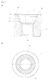
- the selected as an embodiment nut 1 consists essentially of a hollow cylindrical nut body 11 having an internal thread 12.
- the outer contour of the nut 1 corresponds to a common, known in the prior art contour for a positionally correct feed.
- the female thread 12 is adjoined by a fastening contour 13 formed by a countersink.
- the fastening contour 13 comprises a conically widening centering section 14, adjoined by a cylindrically formed outlet section 15, which merges into a likewise cylindrically shaped, diameter-expanded pressing section 16.
- a shoulder 17 is formed, which is formed inclined radially outwardly, so that a conically tapering inwardly annular surface is formed.
- the outlet section 15 is provided in the embodiment with a - not shown - ribbing.
- the depth of the counterbore and thus the fastening contour 13 is matched to the diameter of the internal thread 12.
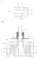
- FIG. 2 a tool for connecting the nut described above with a sheet 8.
- the tool 2 comprises a housing 3, in which a support block 4 is mounted via a spring 7.
- the support block 4 is penetrated by a forming die 5, in the through hole 55, a punching and centering 6 is hineinbewegbar.
- the housing 3 is formed substantially hollow cylindrical. At its upper side, the housing 3 is executed reduced in diameter, whereby a stop 31 is formed to bear the support bracket 4. At its end opposite the stop 31, a ring plate 32 is arranged in the housing 3. The ring plate 32 serves both the support of a spring 7 and the system of the forming die 5, from which it is penetrated.
- the support block 4 is formed substantially cylindrical and has at its the ring plate 32 facing the end of a flange circumferentially integrally formed collar 41. In the middle of the support block 4 is penetrated by a bore 42.
- the forming die 5 is rotationally symmetrical and has a stepped diameter-reduced outer contour, whereby three sections 51, 52, 53 are formed, each with different outer diameters.
- the lower portion 51 facing the support block 4 has an outer diameter that is greater than the inner diameter of the annular plate 32, which corresponds substantially to the outer diameter of the central portion 52, which penetrates the annular plate 32.
- the outer diameter of the bearing block 4 facing upper portion 53 substantially corresponds to the inner diameter of the bore 42 of the support block 4, in which this protrudes.
- the forming die 5 is guided with its upper cutout 53 in the bore 42 of the support block 4.
- a stamping die 54 which is matched to the fastening contour 13 of the nut body 11 of the nut 1, is integrally formed on the upper portion 53.
- a through hole 55 is introduced, the maintenance of the punch die 54 is formed enlarged in diameter, whereby a Stanzbutzenkanal 56 is formed.
- a vertically movable push stamp 9 is arranged by the punching and centering punch 6 is arranged vertically movable relative to the push temple 9.
- the punching and centering punch 6 is formed substantially cylindrical and has an outer diameter which corresponds substantially to the core diameter of the internal thread 12 of the nut 1.
- the punching and centering punch 6 is provided with an annular punching contour.
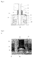
- the sheet 8 is first positioned on the support block 4, after which a nut 1 is placed with its contact surface 18 on the plate 8 on the plate 8. Subsequently, the push-9 is moved vertically to the nut 1, wherein the punching and centering 6 is introduced into the internal thread 12 and the limited by the internal thread 12 passage, whereby the nut is fixed radially on the plate.
- the nut 1 is pressed against the sheet 8 and the punching and centering punch 6 is moved out of the push temple 9 further and moved into the through hole 55 of the forming die 5, whereby a circular punched slug from the sheet 8 is broken, which falls through the Stanzbutzenkanal 56 of the forming die 5.
- a further feed of the thrust temple 9 of the support block 4 is moved against the biasing force of the spring 7, whereby the nut 1 is moved with its fastening contour 13 on the die matrix 54 of the forming die 5.
- the sheet material located in the area of the punched in the sheet 8 hole sheet metal material is shaped collar shaped by the punch die 54 and pressed against the mounting contour 13 of the nut body 11, whereby the connection of sheet 8 and nut 1 is achieved.
- the push plate 9 is moved upwards, which is moved over the restoring force of the spring 7 of the support block 4 against the stop 31 of the housing 3.
- the punching and centering punch 6 is moved out of the internal thread 12 of the nut 11 in further process of the thrust temple 9.
- the sheet 8 connected to the nut 1 can now be removed.
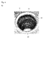
- FIG. 4 played As in FIG. 4a Immediately visible, the sheet metal area located around the hole is formed deep along the fastening contour 13 of the nut 1, wherein material flowing out beyond the pressing portion 16 is received by the outlet portion 15. The fferenauerkeit the nut 1 is given here.
Landscapes
- Engineering & Computer Science (AREA)
- General Engineering & Computer Science (AREA)
- Mechanical Engineering (AREA)
- Automatic Assembly (AREA)
- Bolts, Nuts, And Washers (AREA)
- Connection Of Plates (AREA)
- Forging (AREA)
- Perforating, Stamping-Out Or Severing By Means Other Than Cutting (AREA)
Abstract
Description
- Die Erfindung betrifft eine Mutter zur Befestigung an einem Blech nach dem Oberbegriff des Patentanspruchs 1. Die Erfindung betrifft weiterhin ein Werkzeug zur Verbindung einer solchen Mutter mit einem Blech nach dem Patentanspruch 9, eine Muttern-Blech-Verbindung mit einer solchen Mutter nach dem Patentanspruch 13 sowie ein Verfahren zur Befestigung einer solchen Mutter an einem Blech nach dem Patentanspruch 14.
- Zur Verbindung von Muttern mit einem Blech sind unterschiedliche Lösungen bekannt. So kommen beispielsweise Stanzmuttern zum Einsatz, wie sie unter anderem aus der
DE 36 26 466 bekannt sind. Eine solche Stanzmutter wird in ein nicht vorgelochtes Blech eingepresst und wirkt dabei als Stanzstempel, der einen Butzen aus dem Blech ausstanzt. Die Gegenkraft wird dabei von einer Matrize aufgebracht, die das Blech auf der der Stanzmutter gegenüberliegenden Seite um den auszustanzenden Butzen herum abstützt. Stanzmuttern bei denen während des Einpressvorgangs der Mutter in das Blech ausschließlich das Blech, nicht aber die Mutter selbst verformt wird, sind von den ähnlich gestalteten so genannten Nietmuttern zu unterscheiden, bei denen während des Einpressvorgangs auch die Mutter, teilweise zusätzlich zum Blech, zumeist im freien Ende des Schaftbereichs verformt wird. - Vor dem Hintergrund der aktuellen Blechentwicklung hin zu immer dünneren Blechen erweisen sich die vorbekannten Lösungen als nur bedingt geeignet. Bei Dünnblechen mit Blechstärken von weniger als 1,5 mm werden häufig Nietmuttern verwendet, die einen hohen zeitlichen Montageaufwand benötigen.
- Hier will die Erfindung Abhilfe schaffen. Der Erfindung liegt die Aufgabe zu Grunde, eine Mutter zu Befestigung an einem Blech, insbesondere an einem Dünnblech mit Blechstärken von ≤1,5 mm bereitzustellen, die eine zeit-und aufwandminimierte Befestigung an einem Blech ermöglicht. Gemäß der Erfindung wird diese Aufgabe durch die Merkmale des kennzeichnenden Teils des Patentanspruchs 1 gelöst.
- Mit der Erfindung ist eine Mutter zu Befestigung an einem Blech geschaffen, die eine zeit- und aufwandminimierte Befestigung an dem Blech ermöglicht. Dadurch, dass dem Innengewinde vorgelagert eine gegenüber dem Kerndurchmesser des Innengewindes durchmesservergrößerte Befestigungskontur zur Aufnahme vom Blechmaterial angeordnet ist, ist eine Blechverbindung durch Einformung von Blechmaterial in den Mutternkörper hinein ermöglicht. Die Verbindung von Blech und Mutter wird durch das in Art eines Kragens in den Mutterkörper eingeführte Blechmaterial, das gegen die Befestigungskontur gepresst wird, erzielt. Der Mutternkörper kann sowohl einen runden sowie auch einen mehrkantförmigen Querschnitt aufweisen. Weiterhin kann der Mutternkörper auch endseitig mit einem Flansch versehen sein, wodurch die Anlagefläche an dem Blech vergrößert ist. Das mit der Mutter zu verbindende Blech kann auch als Mehrschicht- beziehungsweise Sandwich blech ausgebildet sein. Weiterhin kann die Mutter auch zum Zwecke der Verbindung von zwei oder mehr Blechen eingesetzt werden.
- In Weiterbildung der Erfindung weist die Befestigungskontur einen Pressabschnitt auf, der in einen gegenüber dem Pressabschnitt durchmesserverminderten Auslaufabschnitt übergeht. Hierdurch ist eine große Anlagefläche für den einzubringenden Blechkragen bereitgestellt, wodurch eine gute Verbindung zwischen Mutter und Blech erzielt ist. Überschüssiges verdrängtes Blechmaterial kann von dem Auslaufabschnitt aufgenommen werden, ohne dass die Schraubengängigkeit der Mutter beeinträchtigt wird.
- In weiterer Ausgestaltung der Erfindung ist zwischen dem Pressabschnitt und dem Auslaufabschnitt ein Absatz ausgebildet. Hierdurch ist der Kraft-Formschluss zwischen Mutter und Blech weiter verbessert. Dabei ist der Absatz bevorzugt als konisch in Richtung des Außenmantels des Mutternkörpers geneigte Ringfläche ausgebildet, wodurch die Festigkeit der Verbindung zwischen Mutter und Blech weiter verbessert ist.
- In Weiterbildung der Erfindung sind der Auslaufabschnitt und/oder der Pressabschnitt zylindrisch ausgebildet. Hierdurch ist die Herstellung des Mutternkörpers vereinfacht.
- In weiterer Ausgestaltung der Erfindung weist die Befestigungskontur einen sich konisch in Richtung des Innengewindes verjüngenden Zentrierabschnitt auf, der sich an das Innengewinde anschließt. Hierdurch ist eine gute Zentrierung des Umformungsstempels relativ zur Mutter ermöglicht.
- In weiterer Ausgestaltung der Erfindung ist der Auslaufabschnitt und/oder der Pressabschnitt zumindest bereichsweise mit einer Verzahnung versehen. Hierdurch ist eine weitere Erhöhung der Festigkeit der Verbindung zwischen Mutter und Blech erzielbar.
- In Weiterbildung der Erfindung ist der Mutternkörper an seiner dem Innengewinde abgewandten Anlagefläche mit einer Verzahnung oder Verrippung versehen. Hierdurch ist eine erhöhte Drehfestigkeit zwischen Mutter und Blech erzielbar.
- Der Erfindung liegt weiterhin die Aufgabe zu Grunde, ein Werkzeug zur Verbindung einer solchen Mutter mit einem Blech bereitzustellen, das eine zeit- und aufwandminimierte Befestigung der Mutter an einem Blech ermöglicht. Gemäß der Erfindung wird diese Aufgabe durch ein Werkzeug mit den Merkmalen des Patentanspruchs 9 gelöst.
- Mit der Erfindung ist ein Werkzeug zur Verbindung einer vorgenannten Mutter mit einem Blech bereitgestellt, dass eine zeit- und aufwandminimierte Befestigung der Mutter an einem Blech ermöglicht. Hierzu weist das Werkzeug einen eine erste Bohrung aufweisenden Auflageblock auf, in der ein eine Durgangsbohrung aufweisender Umformstempel zum Einbringen in die Befestigungskontur des Mutternkörpers der Mutter verschiebbar angeordnet ist. Weiterhin ist ein in die Durchgangsbohrung des Umformstempels bewegbarer Stanz- und Zentrierstempel angeordnet, dessen Außendurchmesser im Wesentlichen dem Kerndurchmesser des Innengewindes der Mutter entspricht. Durch diese Anordnung kann die Befestigung der Mutter über einen einzigen Arbeitsschritt erfolgen, der eine Vorlochung und Blechverdrängung bzw. Blechverprägung oder Blechumlegung in die Befestigungskontur des Mutternkörpers beinhaltet. Durch den in die Durchgangsbohrung des Umformstempels hineinbewegbaren Stanz- und Zentrierstempel kann zunächst das Blech durch den Mutternkörper hindurch gelocht werden. Anschließend kann unter Verbleib des Stanz- und Zentrierstempels in der Mutter der das Loch umgebende Blechbereich über den Umformstempel, der entlang des Stanz- und Zentrierstempels bewegbar ist, in die Befestigungskontur der Mutter umgeformt werden.
- In Weiterbildung der Erfindung weist die Durchgangsbohrung des Umformstempels einen durchmesservergrößerten Abschnitt zur Abfuhr einer von dem Stanz- und Zentrierstempel aus dem Blech ausgestanzten Stanzbutzens auf. Hierdurch ist eine Behinderung des nachfolgenden Umformprozesses durch den Stanzbutzen vermieden.
- In weiterer Ausgestaltung der Erfindung ist der Auflageblock in Verschiebungsrichtung relativ zum Umformstempel federnd gelagert. Hierdurch ist eine Verbringung des Werkzeugs in den Ausgangszustand nach erfolgter Befestigung einer Mutter an einem Blech durch die Rückstellkräfte eines Federelements bewirkt. Dabei ist bevorzugt an dem Umformstempel zumindest bereichsweise umlaufend ein Absatz angeformt, an dem der Auflageblock anschlagbar ist.
- Die Verbindung zwischen einer der vorgenannten Muttern und einem Blech ist bevorzugt derart ausgebildet, dass in das Blech ein Loch eingestanzt ist, wobei ein das Loch umgebender Blechbereich in Art eines Kragens in die Befestigungskontur des Mutternkörpers der Mutter eingeformt ist und an dieser anliegt, wodurch die Verbindung bewirkt ist.
- Der Erfindung liegt weiterhin die Aufgabe zu Grunde, ein Verfahren zur Befestigung einer Mutter der vorgenannten Art an einem Blech bereitzustellen, das eine zeit- und aufwandminimierte Befestigung der Mutter an dem Blech ermöglicht. Gemäß der Erfindung wird diese Aufgabe durch die Merkmale des Patentanspruchs 15 gelöst.
- Mit der Erfindung ist ein Verfahren zur Befestigung einer Mutter der vorgenannten Art an einem Blech bereit gestellt, durch das eine zeit- und aufwandminimierte Befestigung der Mutter an dem Blech ermöglicht. Bevorzugt erfolgt die Lochung des Bleches durch einen Stanz- und Zentrierstempel, der durch das Innengewinde der Mutter (genauer: durch den von dem Innengewinde begrenzten Durchgang der Mutter) geführt wird und das Loch in das Blech stanzt, wobei der Stanz- und Zentrierstempel während des anschließenden Umformprozesses, bei dem der an der Befestigungskontur anliegende Blechkragen gebildet wird, innerhalb des inneren Gewindes der Mutter verbleibt.
- Andere Weiterbildungen und Ausgestaltungen der Erfindung sind in den übrigen Unteransprüchen angegeben. Ein Ausführungsbeispiel der Erfindung ist in den Zeichnungen dargestellt und wird nachfolgend im Einzelnen beschrieben. Es zeigen:
- Figur 1
- die schematische Darstellung einer Mutter
- a) im Längsschnitt;
- b) in der Draufsicht;
- c) in Detaildarstellung des Ausschnitts "B";
- Figur 2
- die schematische Darstellung eines Werkzeugs zur Verbindung der Mutter gemäß
Figur 1 mit einem Blech nach dem Stanzprozess; - Figur 3
- die Darstellung des Werkzeugs nach
Figur 2 nach dem Umformprozess; - Figur 4
- die Ansicht einer Muttern-Blech-Verbindung
- a) im Längsschnitt;
- b) in der Draufsicht.
- Die als Ausführungsbeispiel gewählte Mutter 1 besteht im Wesentlichen aus einem hohlzylindrischen Mutternkörper 11, der ein Innengewinde 12 aufweist.
- Die Außenkontur der Mutter 1 entspricht einer gängigen, im Stand der Technik bekannten Kontur für eine lagegerechte Zuführung. An das Innengewinde 12 schließt sich eine durch eine Aussenkung gebildete Befestigungskontur 13 an. Die Befestigungskontur 13 umfasst einen konisch sich erweiternden Zentrierabschnitt 14, an den sich ein zylindrisch ausgebildeter Auslaufabschnitt 15 anschließt, der in einen ebenfalls zylindrisch ausgebildeten durchmessererweiterten Pressabschnitt 16 übergeht. Zwischen Auslaufabschnitt 15 und Pressabschnitt 16 ist ein Absatz 17 gebildet, der radial nach außen geneigt ausgebildet ist, so dass eine konisch sich nach innen verjüngende Ringfläche gebildet ist. Der Auslaufabschnitt 15 ist im Ausführungsbeispiel mit einer - nicht dargestellten - Verrippung versehen. An seiner dem Innengewinde 12 entgegen gerichteten Anlagefläche 18 ist der Mutternkörper 11 im Ausführungsbeispiel weiterhin mit einer - nicht dargestellten - Sperrverzahnung versehen. Die Tiefe der Aussenkung und damit der Befestigungskontur 13 ist auf den Durchmesser des Innengewindes 12 abgestimmt.
- In
Figur 2 ist ein Werkzeug zur Verbindung der zuvor beschriebenen Mutter mit einem Blech 8 gezeigt. Das Werkzeug 2 umfasst ein Gehäuse 3, in dem ein Auflageblock 4 über eine Feder 7 gelagert ist. Der Auflageblock 4 ist von einem Umformstempel 5 durchdrungen, in dessen Durchgangsbohrung 55 ein Stanz- und Zentrierstempel 6 hineinbewegbar ist. - Das Gehäuse 3 ist im Wesentlichen hohlzylindrisch ausgebildet. An seiner Oberseite ist das Gehäuse 3 durchmesservermindert ausgeführt, wodurch ein Anschlag 31 zur Anlage des Auflagebocks 4 gebildet ist. An seinem dem Anschlag 31 gegenüberliegenden Ende ist in dem Gehäuse 3 eine Ringplatte 32 angeordnet. Die Ringplatte 32 dient sowohl der Auflage einer Feder 7 sowie der Anlage des Umformstempels 5, von dem diese durchdrungen ist.
- Der Auflageblock 4 ist im Wesentlichen zylinderförmig ausgebildet und weist an seinem der Ringplatte 32 zugewandten Ende einen flanschartig umlaufend angeformten Kragen 41 auf. Mittig ist der Auflagebock 4 von einer Bohrung 42 durchdrungen.
- Der Umformstempel 5 ist rotationssymmetrisch ausgebildet und weist eine stufenförmig durchmesserreduzierte Außenkontur auf, wodurch drei Abschnitte 51, 52, 53 mit jeweils unterschiedlichen Außendurchmessern gebildet sind. Der dem Auflageblock 4 entgegengerichtete, untere Abschnitt 51 weist einen Außendurchmesser auf, der größer ist, als der Innendurchmesser der Ringplatte 32, der im Wesentlichen dem Außendurchmesser des mittleren Abschnitts 52 entspricht, der die Ringplatte 32 durchdringt. Der Außendurchmesser des dem Auflagebock 4 zugewandten oberen Abschnitts 53 entspricht im Wesentlichen dem Innendurchmesser der Bohrung 42 des Auflageblocks 4, in den dieser hineinragt. Der Umformstempel 5 ist mit seinem oberen Ausschnitt 53 in der Bohrung 42 des Auflageblocks 4 geführt. Endseitig ist an dem oberen Abschnitt 53 eine auf die Befestigungskontur 13 des Mutternkörpers 11 der Mutter 1 abgestimmte Stempelmatrize 54 angeformt. Entlang seiner Rotationsachse ist in den Umformstempel 5 eine Durchgangsbohrung 55 eingebracht, die unterhalt der Stempelmatrize 54 durchmesservergrößert ausgebildet ist, wodurch ein Stanzbutzenkanal 56 gebildet ist.
- Oberhalb des Gehäuses 3 ist ein vertikal bewegbarer Schubstempel 9 angeordnet, indem der Stanz- und Zentrierstempels 6 vertikal relativ zu dem Schubstempel 9 bewegbar angeordnet ist. Der Stanz- und Zentrierstempel 6 ist im Wesentlichen zylindrisch ausgebildet und weist einen Außendurchmesser auf, der im Wesentlichen dem Kerndurchmesser des Innengewindes 12 der Mutter 1 entspricht. An seinem dem Gehäuse 3 zugewandten Ende ist der Stanz- und Zentrierstempels 6 mit einer kreisringförmige Stanzkontur versehen.
- Zur Befestigung der Mutter 1 an einem Blech 8, dass im Ausführungsbeispiel als Sandwichblech ausgebildet ist, wird das Blech 8 zunächst auf dem Auflageblock 4 positioniert, wonach auf dem Blech 8 eine Mutter 1 mit ihrer Anlagefläche 18 auf dem Blech 8 aufgestellt wird. Nachfolgend wird der Schubstempel 9 vertikal auf die Mutter 1 gefahren, wobei der Stanz- und Zentrierstempel 6 in das Innengewinde 12 bzw. den von dem Innengewinde 12 begrenzten Durchgang eingebracht wird, wodurch die Mutter auf dem Blech radial fixiert wird. Durch den Schubstempel 9 wird die Mutter 1 gegen das Blech 8 gedrückt und der Stanz- und Zentrierstempel 6 wird aus dem Schubstempel 9 weiter herausgefahren und in die Durchgangsbohrung 55 des Umformstempels 5 bewegt, wodurch ein kreisrunder Stanzbutzen aus dem Blech 8 gebrochen wird, der durch den Stanzbutzenkanal 56 des Umformstempels 5 herausfällt. Durch einen weiteren Vorschub des Schubstempels 9 wird der Auflageblock 4 entgegen der Vorspannkraft der Feder 7 bewegt, wodurch die Mutter 1 mit ihrer Befestigungskontur 13 auf die Stempelmatrize 54 des Umformstempels 5 bewegt wird. Hierbei wird das im Bereich des in das Blech 8 eingestanzten Loches befindliche Blechmaterial kragenförmig durch die Stempelmatrize 54 umgeformt und an die Befestigungskontur 13 des Mutternkörpers 11 angepresst, wodurch die Verbindung von Blech 8 und Mutter 1 erzielt ist. Nachfolgend wird der Schubstempel 9 nach oben gefahren, wodurch über die Rückstellkraft der Feder 7 der Auflageblock 4 gegen den Anschlag 31 des Gehäuses 3 verfahren wird. Nachfolgend wird bei weiterem Verfahren des Schubstempels 9 der Stanz- und Zentrierstempel 6 aus dem Innengewinde 12 der Mutter 11 herausbewegt. Das mit der Mutter 1 verbundene Blech 8 kann nun entnommen werden.
- Die so erzielte Verbindung zwischen Mutter 1 und Blech 8 ist in
Figur 4 wiedergegeben. Wie inFigur 4a unmittelbar ersichtlich ist der um das Loch befindliche Blechbereich tief entlang der Befestigungskontur 13 der Mutter 1 hinein umgeformt, wobei über den Pressabschnitt 16 hinausfließendes Material vom Auslaufabschnitt 15 aufgenommen ist. Die Schraubengängigkeit der Mutter 1 ist vorliegend gegeben.
Claims (15)
- Mutter zur Befestigung an einem Blech, mit einem Mutternkörper, der mit einem Innengewinde versehen ist, dadurch gekennzeichnet, dass dem Innengewinde (12) vorgelagert eine gegenüber dem Kerndurchmesser des Innengewindes (12) durchmesservergrößerte Befestigungskontur (13) zur Aufnahme von Blechmaterial angeordnet ist.
- Mutter nach Anspruch 1, dadurch gekennzeichnet, dass die Befestigungskontur (13) einen Pressabschnitt (16) aufweist, der in einen gegenüber dem Pressabschnitt (16) durchmesserverminderten Auslaufabschnitt (15) übergeht.
- Mutter nach Anspruch 2, dadurch gekennzeichnet, dass zwischen dem Pressabschnitt (16) und dem Auslaufabschnitt (15) ein Absatz (17) ausgebildet ist.
- Mutter nach Anspruch 3, dadurch gekennzeichnet, dass der Absatz (17) als konisch in Richtung des Außenmantels des Mutternkörpers (11) geneigte Ringfläche ausgebildet ist.
- Mutter nach einem der Ansprüche 2 bis 4, dadurch gekennzeichnet, dass der Auslaufabschnitt (15) und/oder der Pressabschnitt (16) zylindrisch ausgebildet sind.
- Mutter nach einem der vorgenannten Ansprüche, dadurch gekennzeichnet, dass die Befestigungskontur (13) einen sich konisch in Richtung des Innengewindes verjüngenden Zentrierabschnitt (14) aufweist, der sich an das Innengewinde (12) anschließt.
- Mutter nach einem der Ansprüche 2 bis 6, dadurch gekennzeichnet, dass der Auslaufabschnitt (15) und/oder der Pressabschnitt (16) zumindest bereichsweise mit einer Verzahnung oder Verrippung versehen ist.
- Mutter nach einem der vorgenannten Ansprüche, dadurch gekennzeichnet, dass der Mutternkörper (11) an seiner dem Innengewinde (12) abgewandten Anlagefläche (18) mit einer Verzahnung oder Verrippung versehen ist.
- Werkzeug zur Verbindung einer Mutter (1) nach einem der vorgenannten Ansprüche mit einem Blech (8), umfassend einen eine Bohrung (42) aufweisenden Auflageblock (4), einen in dieser Bohrung (42) verschiebbar angeordneten, eine Durchgangsbohrung (55) aufweisenden Umformstempel (5) zum Einbringen in die Befestigungskontur (13) des Mutternkörpers (11) der Mutter (1) sowie einen in die Durchgangsbohrung (55) des Umformstempels (5) bewegbar angeordneten Stanz- und Zentrierstempel (6), dessen Außendurchmesser im Wesentlichen dem Kerndurchmesser des Innengewindes (12) der Mutter (1) entspricht.
- Werkzeug nach Anspruch 9, dadurch gekennzeichnet, dass die Durchgangsbohrung (55) des Umformstempels (5) einen durchmesservergrößerten Abschnitt zur Abfuhr eines von dem Stanz- und Zentrierstempel (6) aus dem Blech (8) ausgestanzten Stanzbutzens aufweist.
- Werkzeug nach Anspruch 9 oder 10, dadurch gekennzeichnet, dass der Auflageblock (4) in Verschiebungsrichtung relativ zum Umformstempel (5) federnd gelagert ist.
- Werkzeug nach Anspruch 11, dadurch gekennzeichnet, dass an dem Umformstempel (5) zumindest bereichsweise umlaufend ein Absatz angeformt ist, an dem der Auflageblock (4) anschlagbar ist.
- Muttern-Blech-Verbindung, umfassend eine Mutter (1) nach einem der Ansprüche 1 bis 9, die auf ein Blech (8) aufgebracht ist, dadurch gekennzeichnet, dass in das Blech (8) ein Loch eingestanzt ist, wobei ein das Loch umgebender Bereich in Art eines Kragens (81) in die Befestigungskontur (13) des Mutternkörpers (11) der Mutter (1) eingeformt ist und an dieser anliegt, wodurch die Verbindung bewirkt ist.
- Verfahren zur Befestigung einer Mutter (1) nach einem der Ansprüche 1 bis 8 an einem Blech (8), bei dem zunächst in das Blech (8) ein Loch eingebracht wird, dessen Lochdurchmesser kleiner ist, als der Kerndurchmesser des Innengewindes (12) der Mutter (1), nachfolgend die Mutter (1) gegen das Blech (8) gepresst wird, wobei die Mutter (1) derart positioniert wird, dass das Innengewinde (12) zentriert zu dem Loch des Blechs (8) angeordnet ist und wobei ein um das Loch befindlicher Blechbereich in die Befestigungskontur (13) der Mutter (1) hinein umgeformt wird, wodurch ein an der Befestigungskontur (13) anliegender Blechkragen (81) gebildet wird.
- Verfahren nach Anspruch 14, dadurch gekennzeichnet, dass die Lochung des Bleches (8) durch einen Stanz- und Zentrierstempel (6) erfolgt, der durch das Innengewinde (12) der Mutter (1) geführt wird und das Loch in das Blech (8) stanzt, wobei der Stanz- und Zentrierstempel (6) während des anschließenden Umformprozesses, bei dem der an der Befestigungskontur (13) anliegende Blechkragen (81) gebildet wird, in dem Innengewinde (12) der Mutter (1) verbleibt.
Priority Applications (4)
| Application Number | Priority Date | Filing Date | Title |
|---|---|---|---|
| ES14190285.8T ES2664340T3 (es) | 2014-10-24 | 2014-10-24 | Tuerca para la fijación a una chapa |
| EP14190285.8A EP3012470B1 (de) | 2014-10-24 | 2014-10-24 | Mutter zur Befestigung an einem Blech |
| PCT/EP2015/071122 WO2016062462A1 (de) | 2014-10-24 | 2015-09-15 | Mutter zur befestigung an einem blech |
| CN201580056969.3A CN107110192B (zh) | 2014-10-24 | 2015-09-15 | 用于固定在板材处的螺母 |
Applications Claiming Priority (1)
| Application Number | Priority Date | Filing Date | Title |
|---|---|---|---|
| EP14190285.8A EP3012470B1 (de) | 2014-10-24 | 2014-10-24 | Mutter zur Befestigung an einem Blech |
Publications (2)
| Publication Number | Publication Date |
|---|---|
| EP3012470A1 true EP3012470A1 (de) | 2016-04-27 |
| EP3012470B1 EP3012470B1 (de) | 2018-02-21 |
Family
ID=51790607
Family Applications (1)
| Application Number | Title | Priority Date | Filing Date |
|---|---|---|---|
| EP14190285.8A Active EP3012470B1 (de) | 2014-10-24 | 2014-10-24 | Mutter zur Befestigung an einem Blech |
Country Status (4)
| Country | Link |
|---|---|
| EP (1) | EP3012470B1 (de) |
| CN (1) | CN107110192B (de) |
| ES (1) | ES2664340T3 (de) |
| WO (1) | WO2016062462A1 (de) |
Cited By (1)
| Publication number | Priority date | Publication date | Assignee | Title |
|---|---|---|---|---|
| CN108747301A (zh) * | 2018-07-10 | 2018-11-06 | 联德精密材料(中国)股份有限公司 | 超薄板铆合螺母或铆合螺丝装置及其铆合方法 |
Citations (5)
| Publication number | Priority date | Publication date | Assignee | Title |
|---|---|---|---|---|
| US3961412A (en) * | 1974-06-05 | 1976-06-08 | Multifastener Corporation | Method of installing a fastener |
| DE3626466A1 (de) | 1986-08-05 | 1988-02-18 | Lamson & Sessions Gmbh | Einpressmutter |
| US5782594A (en) * | 1996-08-16 | 1998-07-21 | Profil-Verbindungstechnik Gmbh & Co Kg | Self-attaching fastener & method |
| WO2001003881A1 (de) * | 1999-07-09 | 2001-01-18 | Profil Verbindungstechnik Gmbh & Co. Kg | Verfahren zur anbringung eines funktionselementes; matrize; funktionselement; zusammenbauteil und stempelanordnung |
| DE10348851A1 (de) * | 2003-10-21 | 2005-07-07 | Profil Verbindungstechnik Gmbh & Co. Kg | Funktionselement, Funktionselement in Kombination mit einem Blechteil, Verfahren zur Herstellung einer solchen Kombination und Matrize |
Family Cites Families (1)
| Publication number | Priority date | Publication date | Assignee | Title |
|---|---|---|---|---|
| DE69230291T3 (de) * | 1991-11-27 | 2005-08-11 | Henrob Ltd., Flint | Verfahren zur verbindung von platten |
-
2014
- 2014-10-24 EP EP14190285.8A patent/EP3012470B1/de active Active
- 2014-10-24 ES ES14190285.8T patent/ES2664340T3/es active Active
-
2015
- 2015-09-15 CN CN201580056969.3A patent/CN107110192B/zh active Active
- 2015-09-15 WO PCT/EP2015/071122 patent/WO2016062462A1/de not_active Ceased
Patent Citations (5)
| Publication number | Priority date | Publication date | Assignee | Title |
|---|---|---|---|---|
| US3961412A (en) * | 1974-06-05 | 1976-06-08 | Multifastener Corporation | Method of installing a fastener |
| DE3626466A1 (de) | 1986-08-05 | 1988-02-18 | Lamson & Sessions Gmbh | Einpressmutter |
| US5782594A (en) * | 1996-08-16 | 1998-07-21 | Profil-Verbindungstechnik Gmbh & Co Kg | Self-attaching fastener & method |
| WO2001003881A1 (de) * | 1999-07-09 | 2001-01-18 | Profil Verbindungstechnik Gmbh & Co. Kg | Verfahren zur anbringung eines funktionselementes; matrize; funktionselement; zusammenbauteil und stempelanordnung |
| DE10348851A1 (de) * | 2003-10-21 | 2005-07-07 | Profil Verbindungstechnik Gmbh & Co. Kg | Funktionselement, Funktionselement in Kombination mit einem Blechteil, Verfahren zur Herstellung einer solchen Kombination und Matrize |
Cited By (2)
| Publication number | Priority date | Publication date | Assignee | Title |
|---|---|---|---|---|
| CN108747301A (zh) * | 2018-07-10 | 2018-11-06 | 联德精密材料(中国)股份有限公司 | 超薄板铆合螺母或铆合螺丝装置及其铆合方法 |
| CN108747301B (zh) * | 2018-07-10 | 2023-08-22 | 联德精密材料(中国)股份有限公司 | 超薄板铆合螺母或铆合螺丝装置及其铆合方法 |
Also Published As
| Publication number | Publication date |
|---|---|
| CN107110192B (zh) | 2020-01-14 |
| WO2016062462A1 (de) | 2016-04-28 |
| ES2664340T3 (es) | 2018-04-19 |
| EP3012470B1 (de) | 2018-02-21 |
| CN107110192A (zh) | 2017-08-29 |
Similar Documents
| Publication | Publication Date | Title |
|---|---|---|
| WO1994001688A1 (de) | Einpressteil als verbindungselement für auspress- und drehfeste fügeverbindungen | |
| DE102006019405A1 (de) | Werkzeug zur Kaltexpansion von Löchern | |
| DE10135588B4 (de) | Lagerring | |
| EP3031564A1 (de) | Verfahren zum thermischen fügen von bauteilen mittels eines durch einpressen verformten hilfselementes ; vorrichtung zur durchführung dieses verfahrens ; entsprechendes hilfselement | |
| EP3158208B1 (de) | Bauteilverbindung | |
| DE102004042478B4 (de) | Verfahren zur verdrehsicheren Befestigung eines Funktionselements in einem Bauteil sowie Verbindung zwischen einem Bauteil und einem Funktionselement | |
| EP2845679B1 (de) | Verfahren zum einstanzen und befestigen eines befestigungselements | |
| DE102009012243B4 (de) | Stanzmutter, Stanzmutter-Vorrichtung und Stanzmutter-Blechverbindung | |
| EP1003243B1 (de) | Verfahren zur Herstellung einer elektrischen Verbindung zu einem Blechteil und Zusammenbauteil | |
| WO2017098016A1 (de) | Befestigungselement | |
| DE102014207977B4 (de) | Verfahren sowie Einpressvorrichtung zum Ausbilden einer Einpressverbindung zwischen einem Fügeelement und einem vorgelochten Bauteil | |
| EP3157692B1 (de) | Verfahren zum herstellen einer bauteilverbindung | |
| EP3012470B1 (de) | Mutter zur Befestigung an einem Blech | |
| DE10215608B4 (de) | Rohrverbinder | |
| DE102015202776A1 (de) | Befestigungselement | |
| EP2503163A2 (de) | Befestigungseinheit | |
| DE4444857C1 (de) | Verfahren und Vorrichtung zur Herstellung mindestens einer Öffnung in der Wandung eines rohrartigen Teils | |
| DE102018124493B4 (de) | Gelenkgehäuse und Verfahren zur Herstellung eines Gelenkgehäuses | |
| EP2603335B1 (de) | Verfahren und werkzeug zur herstellung eines vollstanznietes | |
| DE10218520B4 (de) | Verfahren zur Herstellung einer Gewindedurchsetzung | |
| DE102015209531B4 (de) | Verfahren zum Herstellen einer Bauteilverbindung | |
| DE202007005755U1 (de) | Vorrichtung zum Stanzen eines Lochs in Blechen mit einer Fase | |
| DE202010008829U1 (de) | Flachteil mit unverlierbar gehaltertem bolzenartigen Teil und bolzenartiges Teil | |
| DE102006018847B4 (de) | Verfahren und Vorrichtung zum Stanzen eines Loches mit kleinem Durchmesser-Längen-Verhältnis | |
| WO2018162629A1 (de) | Verfahren zum verbinden eines sandwich-bauteils |
Legal Events
| Date | Code | Title | Description |
|---|---|---|---|
| PUAI | Public reference made under article 153(3) epc to a published international application that has entered the european phase |
Free format text: ORIGINAL CODE: 0009012 |
|
| AK | Designated contracting states |
Kind code of ref document: A1 Designated state(s): AL AT BE BG CH CY CZ DE DK EE ES FI FR GB GR HR HU IE IS IT LI LT LU LV MC MK MT NL NO PL PT RO RS SE SI SK SM TR |
|
| AX | Request for extension of the european patent |
Extension state: BA ME |
|
| 17P | Request for examination filed |
Effective date: 20160713 |
|
| RBV | Designated contracting states (corrected) |
Designated state(s): AL AT BE BG CH CY CZ DE DK EE ES FI FR GB GR HR HU IE IS IT LI LT LU LV MC MK MT NL NO PL PT RO RS SE SI SK SM TR |
|
| 17Q | First examination report despatched |
Effective date: 20170330 |
|
| GRAP | Despatch of communication of intention to grant a patent |
Free format text: ORIGINAL CODE: EPIDOSNIGR1 |
|
| INTG | Intention to grant announced |
Effective date: 20171106 |
|
| GRAS | Grant fee paid |
Free format text: ORIGINAL CODE: EPIDOSNIGR3 |
|
| GRAA | (expected) grant |
Free format text: ORIGINAL CODE: 0009210 |
|
| AK | Designated contracting states |
Kind code of ref document: B1 Designated state(s): AL AT BE BG CH CY CZ DE DK EE ES FI FR GB GR HR HU IE IS IT LI LT LU LV MC MK MT NL NO PL PT RO RS SE SI SK SM TR |
|
| REG | Reference to a national code |
Ref country code: GB Ref legal event code: FG4D Free format text: NOT ENGLISH |
|
| REG | Reference to a national code |
Ref country code: CH Ref legal event code: EP |
|
| REG | Reference to a national code |
Ref country code: AT Ref legal event code: REF Ref document number: 972074 Country of ref document: AT Kind code of ref document: T Effective date: 20180315 |
|
| REG | Reference to a national code |
Ref country code: IE Ref legal event code: FG4D Free format text: LANGUAGE OF EP DOCUMENT: GERMAN |
|
| REG | Reference to a national code |
Ref country code: DE Ref legal event code: R096 Ref document number: 502014007308 Country of ref document: DE |
|
| REG | Reference to a national code |
Ref country code: ES Ref legal event code: FG2A Ref document number: 2664340 Country of ref document: ES Kind code of ref document: T3 Effective date: 20180419 |
|
| REG | Reference to a national code |
Ref country code: SE Ref legal event code: TRGR |
|
| REG | Reference to a national code |
Ref country code: NL Ref legal event code: MP Effective date: 20180221 |
|
| REG | Reference to a national code |
Ref country code: LT Ref legal event code: MG4D |
|
| PG25 | Lapsed in a contracting state [announced via postgrant information from national office to epo] |
Ref country code: LT Free format text: LAPSE BECAUSE OF FAILURE TO SUBMIT A TRANSLATION OF THE DESCRIPTION OR TO PAY THE FEE WITHIN THE PRESCRIBED TIME-LIMIT Effective date: 20180221 Ref country code: CY Free format text: LAPSE BECAUSE OF FAILURE TO SUBMIT A TRANSLATION OF THE DESCRIPTION OR TO PAY THE FEE WITHIN THE PRESCRIBED TIME-LIMIT Effective date: 20180221 Ref country code: HR Free format text: LAPSE BECAUSE OF FAILURE TO SUBMIT A TRANSLATION OF THE DESCRIPTION OR TO PAY THE FEE WITHIN THE PRESCRIBED TIME-LIMIT Effective date: 20180221 Ref country code: NO Free format text: LAPSE BECAUSE OF FAILURE TO SUBMIT A TRANSLATION OF THE DESCRIPTION OR TO PAY THE FEE WITHIN THE PRESCRIBED TIME-LIMIT Effective date: 20180521 Ref country code: FI Free format text: LAPSE BECAUSE OF FAILURE TO SUBMIT A TRANSLATION OF THE DESCRIPTION OR TO PAY THE FEE WITHIN THE PRESCRIBED TIME-LIMIT Effective date: 20180221 Ref country code: NL Free format text: LAPSE BECAUSE OF FAILURE TO SUBMIT A TRANSLATION OF THE DESCRIPTION OR TO PAY THE FEE WITHIN THE PRESCRIBED TIME-LIMIT Effective date: 20180221 |
|
| PG25 | Lapsed in a contracting state [announced via postgrant information from national office to epo] |
Ref country code: RS Free format text: LAPSE BECAUSE OF FAILURE TO SUBMIT A TRANSLATION OF THE DESCRIPTION OR TO PAY THE FEE WITHIN THE PRESCRIBED TIME-LIMIT Effective date: 20180221 Ref country code: GR Free format text: LAPSE BECAUSE OF FAILURE TO SUBMIT A TRANSLATION OF THE DESCRIPTION OR TO PAY THE FEE WITHIN THE PRESCRIBED TIME-LIMIT Effective date: 20180522 Ref country code: BG Free format text: LAPSE BECAUSE OF FAILURE TO SUBMIT A TRANSLATION OF THE DESCRIPTION OR TO PAY THE FEE WITHIN THE PRESCRIBED TIME-LIMIT Effective date: 20180521 Ref country code: LV Free format text: LAPSE BECAUSE OF FAILURE TO SUBMIT A TRANSLATION OF THE DESCRIPTION OR TO PAY THE FEE WITHIN THE PRESCRIBED TIME-LIMIT Effective date: 20180221 |
|
| PG25 | Lapsed in a contracting state [announced via postgrant information from national office to epo] |
Ref country code: MT Free format text: LAPSE BECAUSE OF FAILURE TO SUBMIT A TRANSLATION OF THE DESCRIPTION OR TO PAY THE FEE WITHIN THE PRESCRIBED TIME-LIMIT Effective date: 20180221 |
|
| REG | Reference to a national code |
Ref country code: FR Ref legal event code: PLFP Year of fee payment: 5 |
|
| PG25 | Lapsed in a contracting state [announced via postgrant information from national office to epo] |
Ref country code: AL Free format text: LAPSE BECAUSE OF FAILURE TO SUBMIT A TRANSLATION OF THE DESCRIPTION OR TO PAY THE FEE WITHIN THE PRESCRIBED TIME-LIMIT Effective date: 20180221 Ref country code: EE Free format text: LAPSE BECAUSE OF FAILURE TO SUBMIT A TRANSLATION OF THE DESCRIPTION OR TO PAY THE FEE WITHIN THE PRESCRIBED TIME-LIMIT Effective date: 20180221 Ref country code: RO Free format text: LAPSE BECAUSE OF FAILURE TO SUBMIT A TRANSLATION OF THE DESCRIPTION OR TO PAY THE FEE WITHIN THE PRESCRIBED TIME-LIMIT Effective date: 20180221 Ref country code: PL Free format text: LAPSE BECAUSE OF FAILURE TO SUBMIT A TRANSLATION OF THE DESCRIPTION OR TO PAY THE FEE WITHIN THE PRESCRIBED TIME-LIMIT Effective date: 20180221 |
|
| REG | Reference to a national code |
Ref country code: DE Ref legal event code: R097 Ref document number: 502014007308 Country of ref document: DE |
|
| PG25 | Lapsed in a contracting state [announced via postgrant information from national office to epo] |
Ref country code: SK Free format text: LAPSE BECAUSE OF FAILURE TO SUBMIT A TRANSLATION OF THE DESCRIPTION OR TO PAY THE FEE WITHIN THE PRESCRIBED TIME-LIMIT Effective date: 20180221 Ref country code: CZ Free format text: LAPSE BECAUSE OF FAILURE TO SUBMIT A TRANSLATION OF THE DESCRIPTION OR TO PAY THE FEE WITHIN THE PRESCRIBED TIME-LIMIT Effective date: 20180221 Ref country code: DK Free format text: LAPSE BECAUSE OF FAILURE TO SUBMIT A TRANSLATION OF THE DESCRIPTION OR TO PAY THE FEE WITHIN THE PRESCRIBED TIME-LIMIT Effective date: 20180221 Ref country code: SM Free format text: LAPSE BECAUSE OF FAILURE TO SUBMIT A TRANSLATION OF THE DESCRIPTION OR TO PAY THE FEE WITHIN THE PRESCRIBED TIME-LIMIT Effective date: 20180221 |
|
| PLBE | No opposition filed within time limit |
Free format text: ORIGINAL CODE: 0009261 |
|
| STAA | Information on the status of an ep patent application or granted ep patent |
Free format text: STATUS: NO OPPOSITION FILED WITHIN TIME LIMIT |
|
| 26N | No opposition filed |
Effective date: 20181122 |
|
| PG25 | Lapsed in a contracting state [announced via postgrant information from national office to epo] |
Ref country code: SI Free format text: LAPSE BECAUSE OF FAILURE TO SUBMIT A TRANSLATION OF THE DESCRIPTION OR TO PAY THE FEE WITHIN THE PRESCRIBED TIME-LIMIT Effective date: 20180221 |
|
| REG | Reference to a national code |
Ref country code: CH Ref legal event code: PL |
|
| GBPC | Gb: european patent ceased through non-payment of renewal fee |
Effective date: 20181024 |
|
| REG | Reference to a national code |
Ref country code: BE Ref legal event code: MM Effective date: 20181031 |
|
| PG25 | Lapsed in a contracting state [announced via postgrant information from national office to epo] |
Ref country code: LU Free format text: LAPSE BECAUSE OF NON-PAYMENT OF DUE FEES Effective date: 20181024 Ref country code: MC Free format text: LAPSE BECAUSE OF FAILURE TO SUBMIT A TRANSLATION OF THE DESCRIPTION OR TO PAY THE FEE WITHIN THE PRESCRIBED TIME-LIMIT Effective date: 20180221 |
|
| REG | Reference to a national code |
Ref country code: IE Ref legal event code: MM4A |
|
| PG25 | Lapsed in a contracting state [announced via postgrant information from national office to epo] |
Ref country code: LI Free format text: LAPSE BECAUSE OF NON-PAYMENT OF DUE FEES Effective date: 20181031 Ref country code: BE Free format text: LAPSE BECAUSE OF NON-PAYMENT OF DUE FEES Effective date: 20181031 Ref country code: CH Free format text: LAPSE BECAUSE OF NON-PAYMENT OF DUE FEES Effective date: 20181031 |
|
| PG25 | Lapsed in a contracting state [announced via postgrant information from national office to epo] |
Ref country code: IE Free format text: LAPSE BECAUSE OF NON-PAYMENT OF DUE FEES Effective date: 20181024 Ref country code: GB Free format text: LAPSE BECAUSE OF NON-PAYMENT OF DUE FEES Effective date: 20181024 |
|
| PG25 | Lapsed in a contracting state [announced via postgrant information from national office to epo] |
Ref country code: TR Free format text: LAPSE BECAUSE OF FAILURE TO SUBMIT A TRANSLATION OF THE DESCRIPTION OR TO PAY THE FEE WITHIN THE PRESCRIBED TIME-LIMIT Effective date: 20180221 |
|
| PG25 | Lapsed in a contracting state [announced via postgrant information from national office to epo] |
Ref country code: PT Free format text: LAPSE BECAUSE OF FAILURE TO SUBMIT A TRANSLATION OF THE DESCRIPTION OR TO PAY THE FEE WITHIN THE PRESCRIBED TIME-LIMIT Effective date: 20180221 |
|
| PG25 | Lapsed in a contracting state [announced via postgrant information from national office to epo] |
Ref country code: HU Free format text: LAPSE BECAUSE OF FAILURE TO SUBMIT A TRANSLATION OF THE DESCRIPTION OR TO PAY THE FEE WITHIN THE PRESCRIBED TIME-LIMIT; INVALID AB INITIO Effective date: 20141024 Ref country code: MK Free format text: LAPSE BECAUSE OF NON-PAYMENT OF DUE FEES Effective date: 20180221 |
|
| PG25 | Lapsed in a contracting state [announced via postgrant information from national office to epo] |
Ref country code: IS Free format text: LAPSE BECAUSE OF FAILURE TO SUBMIT A TRANSLATION OF THE DESCRIPTION OR TO PAY THE FEE WITHIN THE PRESCRIBED TIME-LIMIT Effective date: 20180621 |
|
| REG | Reference to a national code |
Ref country code: AT Ref legal event code: MM01 Ref document number: 972074 Country of ref document: AT Kind code of ref document: T Effective date: 20191024 |
|
| PG25 | Lapsed in a contracting state [announced via postgrant information from national office to epo] |
Ref country code: AT Free format text: LAPSE BECAUSE OF NON-PAYMENT OF DUE FEES Effective date: 20191024 |
|
| PGFP | Annual fee paid to national office [announced via postgrant information from national office to epo] |
Ref country code: DE Payment date: 20251015 Year of fee payment: 12 |
|
| PGFP | Annual fee paid to national office [announced via postgrant information from national office to epo] |
Ref country code: IT Payment date: 20251031 Year of fee payment: 12 |
|
| PGFP | Annual fee paid to national office [announced via postgrant information from national office to epo] |
Ref country code: FR Payment date: 20251024 Year of fee payment: 12 |
|
| PGFP | Annual fee paid to national office [announced via postgrant information from national office to epo] |
Ref country code: SE Payment date: 20251023 Year of fee payment: 12 |
|
| PGFP | Annual fee paid to national office [announced via postgrant information from national office to epo] |
Ref country code: ES Payment date: 20251114 Year of fee payment: 12 |