EP3012502A1 - Schlauch und anschlussvorrichtung für einen schlauch - Google Patents
Schlauch und anschlussvorrichtung für einen schlauch Download PDFInfo
- Publication number
- EP3012502A1 EP3012502A1 EP15185497.3A EP15185497A EP3012502A1 EP 3012502 A1 EP3012502 A1 EP 3012502A1 EP 15185497 A EP15185497 A EP 15185497A EP 3012502 A1 EP3012502 A1 EP 3012502A1
- Authority
- EP
- European Patent Office
- Prior art keywords
- screw
- connecting element
- hose
- annular groove
- metal
- Prior art date
- Legal status (The legal status is an assumption and is not a legal conclusion. Google has not performed a legal analysis and makes no representation as to the accuracy of the status listed.)
- Granted
Links
Images


Classifications
-
- F—MECHANICAL ENGINEERING; LIGHTING; HEATING; WEAPONS; BLASTING
- F16—ENGINEERING ELEMENTS AND UNITS; GENERAL MEASURES FOR PRODUCING AND MAINTAINING EFFECTIVE FUNCTIONING OF MACHINES OR INSTALLATIONS; THERMAL INSULATION IN GENERAL
- F16L—PIPES; JOINTS OR FITTINGS FOR PIPES; SUPPORTS FOR PIPES, CABLES OR PROTECTIVE TUBING; MEANS FOR THERMAL INSULATION IN GENERAL
- F16L25/00—Construction or details of pipe joints not provided for in, or of interest apart from, groups F16L13/00 - F16L23/00
- F16L25/0036—Joints for corrugated pipes
- F16L25/0045—Joints for corrugated pipes of the quick-acting type
-
- F—MECHANICAL ENGINEERING; LIGHTING; HEATING; WEAPONS; BLASTING
- F16—ENGINEERING ELEMENTS AND UNITS; GENERAL MEASURES FOR PRODUCING AND MAINTAINING EFFECTIVE FUNCTIONING OF MACHINES OR INSTALLATIONS; THERMAL INSULATION IN GENERAL
- F16L—PIPES; JOINTS OR FITTINGS FOR PIPES; SUPPORTS FOR PIPES, CABLES OR PROTECTIVE TUBING; MEANS FOR THERMAL INSULATION IN GENERAL
- F16L33/00—Arrangements for connecting hoses to rigid members; Rigid hose-connectors, i.e. single members engaging both hoses
- F16L33/24—Arrangements for connecting hoses to rigid members; Rigid hose-connectors, i.e. single members engaging both hoses with parts screwed directly on or into the hose
-
- F—MECHANICAL ENGINEERING; LIGHTING; HEATING; WEAPONS; BLASTING
- F16—ENGINEERING ELEMENTS AND UNITS; GENERAL MEASURES FOR PRODUCING AND MAINTAINING EFFECTIVE FUNCTIONING OF MACHINES OR INSTALLATIONS; THERMAL INSULATION IN GENERAL
- F16L—PIPES; JOINTS OR FITTINGS FOR PIPES; SUPPORTS FOR PIPES, CABLES OR PROTECTIVE TUBING; MEANS FOR THERMAL INSULATION IN GENERAL
- F16L33/00—Arrangements for connecting hoses to rigid members; Rigid hose-connectors, i.e. single members engaging both hoses
- F16L33/26—Arrangements for connecting hoses to rigid members; Rigid hose-connectors, i.e. single members engaging both hoses specially adapted for hoses made of metal
-
- F—MECHANICAL ENGINEERING; LIGHTING; HEATING; WEAPONS; BLASTING
- F16—ENGINEERING ELEMENTS AND UNITS; GENERAL MEASURES FOR PRODUCING AND MAINTAINING EFFECTIVE FUNCTIONING OF MACHINES OR INSTALLATIONS; THERMAL INSULATION IN GENERAL
- F16L—PIPES; JOINTS OR FITTINGS FOR PIPES; SUPPORTS FOR PIPES, CABLES OR PROTECTIVE TUBING; MEANS FOR THERMAL INSULATION IN GENERAL
- F16L37/00—Couplings of the quick-acting type
- F16L37/08—Couplings of the quick-acting type in which the connection between abutting or axially overlapping ends is maintained by locking members
- F16L37/084—Couplings of the quick-acting type in which the connection between abutting or axially overlapping ends is maintained by locking members combined with automatic locking
- F16L37/088—Couplings of the quick-acting type in which the connection between abutting or axially overlapping ends is maintained by locking members combined with automatic locking by means of a split elastic ring
-
- E—FIXED CONSTRUCTIONS
- E03—WATER SUPPLY; SEWERAGE
- E03C—DOMESTIC PLUMBING INSTALLATIONS FOR FRESH WATER OR WASTE WATER; SINKS
- E03C1/00—Domestic plumbing installations for fresh water or waste water; Sinks
- E03C1/02—Plumbing installations for fresh water
- E03C1/025—Water supply lines as such, e.g. shower hoses
Definitions
- a hose of the present type consists at least of a metal hose and a connection device which is attached to one end of the metal hose and serves for connecting the hose to another component.
- the metal tube is made of one or more helically wound profiles and is therefore also referred to as a winding tube.
- hoses are used in a variety of applications, such as in the electrical industry and mechanical engineering for the protection of electrical cables and for the protection of optical fibers and other sensitive cables. Also for the protection of flexible shafts and hoses winding tubes are used; Thus, a hose of the present type can also be used as a shower hose.
- a hose of the present type is for example from the DE 27 57 901 A1 known.
- the connection device comprises a screw-in part for insertion into the metal hose, wherein the screw-in part has a screw-in area and a connection area.
- the screw-in area of the screw-in part is provided with at least one web which essentially describes a helical line and engages in the profiles of the metal hose, in order to form a positive locking against axial movements of the screw-in part in the metal hose.
- a hose of the present type is in EP 2 716 824 A2 disclosed.
- the screw-in part of the connection device is from the Einschraub Scheme to the end of the hose towards a connection region, which is configured as a connection flange with a radial sealing surface.
- connection devices to attach the hose to a further component, for example a valve
- a further component for example a valve
- a union nut or a screw-on sleeve is used which engages behind the flange of the screw-in part and presses it against a sealing surface of this component when screwed onto a corresponding external thread on the further component
- Hoses of the present type are usually completed on site, i.
- the metal tube which is available by the meter, is cut to the required length on site, after which the connecting device is attached to the end of the metal tube.
- the union nut or Aufschraubhülse must first be threaded onto the metal tube, after which the screw is inserted into the metal tube or placed on this.
- the connection device comprises an outer casing and / or an inner hose in addition to the metal hose, further components are required for the connection device, so that the assembly of the connection device is cumbersome and can - especially on construction sites - lead to errors that a permanent connection between the connection device and affect the metal hose.
- connection devices that do not rely on the component to which the hose is to be connected to provide a sealing surface for a flange as well as an external thread for the union nut or Aufschraubhülse. Rather, it should also be possible to use a connection device with a connection piece, which has an external thread, in order to be able to screw this connection piece into an internal thread of a secondary component. For some applications, connectors are desirable.
- the present invention is therefore based on the object to provide a hose of the type mentioned above and a connection device for such a hose, which is easy to assemble, allows different connection techniques for connecting the hose to another component and the disadvantage of co-rotation of the hose Ansch manen avoids.
- a hose designed according to the invention is accordingly distinguished from known hoses by the connecting device according to the invention, which as before comprises a screw-in part for insertion into and / or for mounting on the metal hose and a screw-in area with at least one web for screwing or screwing into or onto the Has metal hose.
- the connecting device according to the invention also comprises a connecting element, which is fastened to the connecting portion of the screw-in and serves to connect the hose with another component.
- This connector expands the possibilities for connection to a secondary component, since it can be in all possible forms, for example, as a male thread, as a screw-on with internal thread, as a connector, as a flange and much more.
- the connecting element according to the invention can be plugged onto the screw-in part or inserted into this and forms an overlap region with the connecting region of the screw-in part.
- the opposing surfaces of the connecting element and the screw-in in the overlap region describe coaxial cylindrical or conical lateral surfaces, so that the connecting element is freely rotatable relative to the screwed part about the common axis.
- the connecting element in the overlapping region according to the invention has a first annular groove, while the screw-in part in the overlapping region, opposite the first annular groove, is provided with a second annular groove.
- the first and second annular grooves form an annular space when they face each other in the overlapping area.
- a snap ring is arranged, which sits partly in the first annular groove and partly in the second annular groove and thus fixes the connecting element axially on the screw without hindering the free rotation of the connecting element relative to the screw about the common axis.
- the connecting element is thus rotatably attached to the screw-in part, which solves the previously existing problem that the hose rotates when screwing on a continuing component.
- the fastening of the connecting element according to the invention on the screw-in part results in the widest variety of possibilities for the shaping of the connecting element, such as, for example, a socket with external thread, sleeve with internal thread, flange or plug connection.
- connection device is very easy to assemble: It is sufficient to screw the screw in the metal hose or screwed onto this, wherein expediently the snap ring is already in the annular groove of the screw. Then only the connecting element has to be plugged onto the screw-in part or plugged into this - depending on the configuration of these two components -, wherein the snap ring reduces its diameter by means of its elastic properties or increases and allows the mating of the two parts.
- the snap ring expands again due to its elastic properties or reduces its diameter again, so that it is partly in the first and partly seated in the second annular groove.
- the snap ring thus locks the annular grooves to one another and prevents relative axial movements between the connecting element and the screw-in part, but not rotational movements about the common axis.
- annular grooves for forming a sealing seat for a ring seal may be provided in the overlapping area between the connecting element and the screw-in part.
- ring grooves can be provided only in the connecting element or in the screw-in part, or in turn in each case in both components, wherein in the latter case these in turn each form an annular space.
- connection device The ease of installation of the connecting device according to the invention is improved when the connecting element continues from the overlap region hose side in an insertion region which receives the end of the metal tube and preferably has a conically tapered inner surface to facilitate the insertion of the metal tube.
- the insertion area also simplifies the diameter reduction of the snap ring, which is necessary in order to be able to attach the connecting element to the screw-in part.
- the metal hose can be surrounded on the outside by a plastic hose or a plastic layer, which protects it against the environment.
- the end of the metal tube is such in the preferably present Insertion of the connecting element used, that the plastic tube or the plastic layer is pressed circumferentially against the inner surface of the insertion region of the connecting element. Due to the flexibility of a plastic tube or a plastic layer, this results in a sealing effect.
- the metal tube is, as is known, also in the context of the present invention preferably a Agraffschlauch from Agraffprofilen.
- the present invention is not limited to this profile shape.
- the connecting device expediently comprises an inner sleeve for insertion into the inner tube, which clamps the inner tube between itself and the screw-in part or between itself and the metal tube.
- This inner sleeve is attached to the screw and / or on the connecting element, or it is held between the screw and the connecting element, so that ultimately the inner tube is fixed to the connecting element and thereby forms a double Auszieh rejoin for the connecting device, since axial pull-both in the metal hose as well as in the inner tube are introduced.
- At least one circumferential seal can be provided between the connecting element and the inner sleeve, so that the inner tube can be fluid-tightly connected to a further component to which the hose is connected.
- the connecting device according to the invention is preferably not detachable as soon as the connecting element and the screw-in part are latched together via the snap ring.
- this latching connection can also be provided to design this latching connection releasably.
- the first and / or the second annular groove are provided with chamfered groove walls, so that at correspondingly high axial forces of the snap ring due to the chamfered groove walls reduces its diameter (or widening), whereby the locking is released.
- the screw-in part is fixed on or in the metal tube by means of an adhesive substance.
- This adhesive prevents the screw-in part from being able to disengage from the metal hose by means of rotational movements. It suffice for this relatively weak Adotrosiv specification; because the axial extraction forces are introduced via the web of the screw into the metal hose.
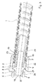
- FIGS. 1 to 4 illustrated embodiments of an inventively designed hose each comprise a metal hose 1, which consists of a wound Agraffprofil, a screw-2 with a round wire snap ring 3 and a connecting element 4 which is rotatably mounted on the snap ring 2 on the screw 2.
- the connecting element 4 has at its end a connecting piece 5 with an external thread 6 in order to be able to connect the hose to a further component (not shown).
- a ring seal 7 is arranged behind the external thread 6.
- the connecting element 4 also has an external hexagon 8 in order to facilitate screwing into a further component.
- the connecting element 4 is provided with an insertion region 9 which has a conically tapered inner surface 10 in order to facilitate the attachment of the connecting element 4 to the metal hose 1 and the screw-in part 2.
- the screw-in part 2 consists of a screw-in area 11 and an adjoining connecting area 12.
- the screw-in area 11 is provided for insertion into the metal tube 1, while the connecting area 12 remains outside the metal tube 1.
- the connecting region 12 forms an axially extending, circumferential lateral surface with a second annular groove 13, in which the snap ring 3 is held.
- an overlap region 14 in which the outer surface of the connecting portion 12 and the, also an axially extending, circumferential circumferential surface forming, inner surface of the connecting element 4 are opposite.
- the connecting element 4 has in the overlapping region 14, a first annular groove 15, which forms a circumferential in the overlap region 14 annular space with the second annular groove 13.
- the snap ring 3 sits in such a way in the annular space formed by the annular grooves 13, 15, that the connecting element 4 does not move axially relative to the screw 2. However, it is freely rotatable about a common axis 16; this rotation is not hindered by the snap ring 3.
- the second annular groove 13 in the screw 2 is designed so deep that the snap ring 3 completely fits into it, if its diameter is reduced. This allows the attachment of the connecting element 4 on the screw-2, supported by the tapered inner surface 10 of the insertion portion 9 of the connecting element 4.
- the first annular groove 15 in the connecting element 4 provided with a smaller depth, so that the snap ring 3, when in wants to elastically deform its original extent, can only extend to the bottom of the first annular groove 15 and a small elastic expansion force remains.
- the geometry of the first annular groove 15 is in this case selected so that the snap ring 3 then sits in approximately half of its cross section in the first annular groove 15 and the other half of its cross section in the second annular groove 13.
- the connecting element 4 is fixed with respect to axial movements on the screw 2. At the same time this type of attachment does not hinder rotational movement of the connecting element relative to the screw-in part 2.
- the screw-2 has a circumferential web 17 at its Einschraub Colour 11. This describes a helical line with a slope that corresponds to the pitch of the windings of the metal tube 1. This is in FIG. 5 clarified. Like again FIG. 1 best shows, engages the web 17 in the Agraffprofil of the metal tube 1 and forms such a positive connection against axial withdrawal of the screw 2 from the metal tube 1. This positive connection is due to the corresponding slopes of the Agraffprofils and the web 17 by simply screwing the Screw 2 in the end of the metal tube 1 has been prepared.
- FIG. 2 illustrated embodiment differs from that FIG. 1 on the one hand, that the metal hose 1 is surrounded by a plastic tube 8, the metal hose 1 against the environment protects. Furthermore, an O-ring seal 19 is arranged in the overlapping region 14 between the connecting element 4 and the screw-in part 2, which is seated in a screw-in part 2 in a seal groove designed as a further annular groove 20.
- the O-ring seal 19 ensures that the interior of the connection device is sealed liquid-tight on the hose side to the outside. Another sealing effect results from the fact that the outer plastic tube 18 is pressed from the metal tube 1 against the chamfered inner surface 10 of the insertion region 9 of the connecting element 4 all around. Apart from the fact that the metal hose 1 in FIG. 2 is wound from a simple hook profile, there are no further differences from the embodiment according to FIG. 1 ,
- FIG. 3 illustrated embodiment differs from the exemplary embodiment FIG. 1 essentially in that in addition an inner tube 21 is present, in which an inner sleeve 22 is inserted.
- the inner sleeve 22 pushes the inner tube 21 from the inside against the Einschraub Colour 11 of the screw 2, which forms, in conjunction with hook-shaped retaining rings 23 on the outer circumference of the inner sleeve 22, a pull-out, ie the inner tube 21 is fixed to the inner sleeve 22.
- the inner sleeve 22 is the end in a flange 24 and an adjoining nipple 25 away.
- the nipple 25 carries two O-ring seals 26, with which the interior of the inner sleeve 22 and thus the interior of the inner tube 21 is sealed to the outside.
- the flange 24 is seated between the screw 2 and the connecting element 4 and is thus fixed between this form-fitting axially. Pull-out forces acting on the connection device are thus introduced to the one on the snap ring 3 and the screw 2 in the metal hose 1, and at the same time on the flange 24 and the inner sleeve 22 in the inner tube 21st
- FIG. 4 shows an embodiment, which is essentially a combination of the embodiments of the Figures 2 and 3 corresponds to: the metal hose 1, which in turn is wound from simple hook profiles, is surrounded by a plastic tube 18 and simultaneously performs an inner tube 21, which is why the in FIG. 3 already shown inner sleeve 22 is present.
- the connecting element 4 and the screw-2 are formed as shown in Figure 2, ie in the overlap region 14 is adjacent to the first and second annular grooves 13, 15 with the snap ring 3, a further annular groove 20 with an O-ring seal 19th
- the assembly of the connecting device according to the invention, as described for example in FIG. 3 is performed in the following steps: First, the in FIG. 5 shown screwed 2 or on the web 17 applied an adhesive, and then screwed the screw 2 into the metal tube 1. The adhesive prevents the screw-2 can be unscrewed out of the metal tube 1 after installation. Then, the inner sleeve 22 is inserted into the screw-in and the inner tube 21.
- connection device After insertion of the snap ring 3 in the second annular groove 13 of the screw 2 results in the situation as in FIG. 6 is shown; the connection device is pre-assembled. Now, the connecting element 4 is attached to the connecting portion 12 of the screw 2. Here, the chamfered inner surface 10 of the insertion region 9 of the connecting element 4 helps to reduce the snap ring 3 in its diameter. As soon as the first annular groove 15 in the overlapping region 14 of the connecting element 4 faces the second annular groove 13 in the screw-in part 2, the snap ring 3 snaps into the first annular groove 15, so that the connecting element 4 is latched onto the screw-in part 2. The connection device is then completed and the hose can be connected to a further component.
Landscapes
- Engineering & Computer Science (AREA)
- General Engineering & Computer Science (AREA)
- Mechanical Engineering (AREA)
- Joints That Cut Off Fluids, And Hose Joints (AREA)
Description
- Die Erfindung betrifft einen Schlauch nach dem Oberbegriff des Anspruchs 1 sowie eine Anschlussvorrichtung für einen solchen Schlauch. Ein Schlauch der vorliegenden Art besteht demnach zumindest aus einem Metallschlauch und einer Anschlussvorrichtung, die an einem Ende des Metallschlauchs an diesem angebracht ist und zum Verbinden des Schlauchs mit einem anderen Bauteil dient. Der Metallschlauch ist aus einem oder mehreren helixförmig gewickelten Profilen gefertigt und wird daher auch als Wickelschlauch bezeichnet.
- Solche Schläuche werden in unterschiedlichen Anwendungsbereichen eingesetzt, wie beispielsweise in der Elektroindustrie und im Maschinenbau zum Schutz elektrischer Kabel sowie zum Schutz von Lichtleitern und anderen empfindlichen Leitungen. Auch zum Schutz von biegsamen Wellen und Schläuchen werden Wickelschläuche eingesetzt; so kann ein Schlauch der vorliegenden Art auch als Brauseschlauch eingesetzt werden.
- Ein Schlauch der vorliegenden Art ist beispielsweise aus der
DE 27 57 901 A1 bekannt. Dort umfasst die Anschlussvorrichtung ein Einschraubteil zum Einsetzen in den Metallschlauch, wobei das Einschraubteil einen Einschraubbereich und einen Verbindungsbereich aufweist. Der Einschraubbereich des Einschraubteils ist mit mindestens einem Steg versehen, welcher im Wesentlichen eine Schraubenlinie beschreibt und in die Profile des Metallschlauchs eingreift, um mit diesem einen Formschluss gegen axiale Bewegungen des Einschraubteils im Metallschlauch zu bilden. - Ein weiteres Beispiel für einen Schlauch der vorliegenden Art ist in der
EP 2 716 824 A2 offenbart. Es handelt sich dort um einen Brauseschlauch, und das Einschraubteil der Anschlussvorrichtung setzt sich vom Einschraubbereich zum Ende des Schlauchs hin in einen Verbindungsbereich fort, der als Anschlussflansch mit radialer Dichtfläche ausgestaltet ist. - Um mit den bekannten Anschlussvorrichtungen den Schlauch an ein weiterführendes Bauteil, beispielsweise eine Armatur, anzuschießen, wird herkömmlicherweise eine Überwurfmutter oder eine Aufschraubhülse verwendet, die den Flansch des Einschraubteils hintergreift und diesen beim Aufschrauben auf ein entsprechendes Außengewinde am weiterführenden Bauteil gegen eine Dichtfläche dieses Bauteils drückt.
- Schläuche der vorliegenden Art werden in der Regel vor Ort fertiggestellt, d.h. der als Meterware vorliegende Metallschlauch wird vor Ort auf die benötigte Länge abgeschnitten, wonach die Anschlussvorrichtung am Ende des Metallschlauchs angebracht wird. Hierfür muss zunächst die Überwurfmutter oder Aufschraubhülse auf den Metallschlauch aufgefädelt werden, wonach das Einschraubteil in den Metallschlauch eingesetzt oder auf diesen aufgesetzt wird. Soweit der Schlauch zusätzlich zum Metallschlauch eine äußere Ummantelung und/oder einen Innenschlauch umfasst, sind weitere Bauteile für die Anschlussvorrichtung notwendig, so dass die Montage der Anschlussvorrichtung umständlich ist und - insbesondere auf Baustellen - zu Fehlern führen kann, die eine dauerhafte Verbindung zwischen der Anschlussvorrichtung und dem Metallschlauch beeinträchtigen können.
- Daneben besteht oft das Problem, dass sich der Schlauch beim Aufschrauben der Überwurfmutter bzw. der Aufschraubhülse auf ein Gewinde eines weiterführenden Bauteils mitdreht, was nachteilige Verwindungen des Metallschlauchs bzw. von dessen Profilen zur Folge haben kann. Diese Problematik besteht auch bei vorgefertigten Schläuchen, deren Anschlussvorrichtungen bereits am Metallschlauch angebracht sind.
- Schließlich gibt es Bedarf, Anschlussvorrichtungen zu verwenden, die nicht darauf angewiesen sind, dass das Bauteil, an das der Schlauch angeschlossen werden soll, eine Dichtungsfläche für einen Flansch sowie für ein Außengewinde für die Überwurfmutter bzw. die Aufschraubhülse aufweist. Es sollte vielmehr auch möglich sein, eine Anschlussvorrichtung mit einem Anschlussstutzen, der ein Außengewinde aufweist, zu verwenden, um diesen Anschlussstutzen in ein Innengewinde eines weiterführenden Bauteils einschrauben zu können. Für manche Anwendungsfälle sind auch Steckverbindungen wünschenswert.
- Der vorliegenden Erfindung liegt daher die Aufgabe zugrunde, einen Schlauch der eingangs genannten Art sowie eine Anschlussvorrichtung für einen solchen Schlauch vorzuschlagen, der leicht zu montieren ist, unterschiedliche Anschlusstechniken für das Anschließen des Schlauchs an ein anderes Bauteil ermöglicht und den Nachteil eines Mitdrehens des Schlauchs beim Anschießen vermeidet.
- Gelöst ist diese Aufgabe durch einen Schlauch mit den Merkmalen des Anspruchs 1 sowie durch eine Anschlussvorrichtung mit den Merkmalen des Anspruchs 11. Bevorzugte Ausgestaltungen des erfindungsgemäßen Schlauchs finden sich in den Ansprüchen 2 bis 10; vorteilhafte Weiterbildungen der erfindungsgemäßen Anschlussvorrichtung sind in den Ansprüchen 12 bis 16 niedergelegt.
- Ein erfindungsgemäß ausgebildeter Schlauch zeichnet sich gegenüber bekannten Schläuchen demnach durch die erfindungsgemäße Anschlussvorrichtung aus, welche wie bisher ein Einschraubteil zum Einsetzen in den und/oder zum Aufsetzen auf den Metallschlauch umfasst und einen Einschraubbereich mit mindestens einem Steg zum Einschrauben oder Aufschrauben in den oder auf den Metallschlauch aufweist. Anders als im Stand der Technik umfasst die erfindungsgemäße Anschlussvorrichtung außerdem ein Verbindungselement, welches am Verbindungsbereich des Einschraubteils befestigbar ist und zum Verbinden des Schlauchs mit einem anderen Bauteil dient. Dieses Verbindungselement erweitert die Möglichkeiten für den Anschluss mit einem weiterführenden Bauteil, da es in allen möglichen Formen vorliegen kann, beispielsweise als Stutzen mit Außengewinde, als Aufschraubteil mit Innengewinde, als Steckverbinder, als Flansch und vieles mehr.
- Das Verbindungselement ist erfindungsgemäß auf das Einschraubteil aufsteckbar oder in dieses einsteckbar und bildet hierbei einen Überlappungsbereich mit dem Verbindungsbereich des Einschraubteils. Die im Überlappungsbereich einander gegenüberliegenden Flächen des Verbindungselements und des Einschraubteils beschreiben koaxiale zylindrische oder konische Mantelflächen, so dass das Verbindungselement gegenüber dem Einschraubteil um die gemeinsame Achse frei drehbar ist. Zum Befestigen des Verbindungselements am Einschraubteil weist das Verbindungselement im Überlappungsbereich erfindungsgemäß eine erste Ringnut auf, während das Einschraubteil im Überlappungsbereich, der ersten Ringnut gegenüberliegend, mit einer zweiten Ringnut versehen ist. Die erste und die zweite Ringnut bilden, wenn sie im Überlappungsbereich einander gegenüberliegen, einen Ringraum. In diesem Ringraum ist ein Sprengring angeordnet, der zum Teil in der ersten Ringnut und zum Teil in der zweiten Ringnut sitzt und so das Verbindungselement axial am Einschraubteil festlegt, ohne die freie Drehbarkeit des Verbindungselements gegenüber dem Einschraubteil um die gemeinsame Achse zu behindern.
- Gemäß der vorliegenden Erfindung ist das Verbindungselement also drehbar am Einschraubteil befestigt, was das bislang bestehende Problem löst, dass sich der Schlauch beim Aufschrauben auf ein weiterführendes Bauteil mitdreht. Gleichzeitig ergeben sich durch die erfindungsgemäße Befestigung des Verbindungselements am Einschraubteil die unterschiedlichsten Möglichkeiten für die Ausformung des Verbindungselements, wie beispielsweise als Stutzen mit Außengewinde, Hülse mit Innengewinde, Flansch oder Steckverbindung.
- Schließlich ist die erfindungsgemäße Anschlussvorrichtung sehr leicht zu montieren: Es genügt, das Einschraubteil in den Metallschlauch einzuschrauben oder auf diesen aufzuschrauben, wobei zweckmäßigerweise der Sprengring bereits in der Ringnut des Einschraubteils sitzt. Sodann muss nur noch das Verbindungselement auf das Einschraubteil aufgesteckt oder in dieses eingesteckt werden - je nach Ausgestaltung dieser beiden Bauteile -, wobei der Sprengring mittels seiner elastischen Eigenschaften seinen Durchmesser verringert bzw. vergrößert und so das Zusammenstecken der beiden Teile ermöglicht. Sobald die erste Ringnut im Verbindungselement auf der Höhe der zweiten Ringnut im Einschraubteil ankommt, sich die beiden Ringnuten also gegenüberliegen und einen Ringraum bilden, dehnt sich der Sprengring aufgrund seiner elastischen Eigenschaften wieder aus oder verringert seinen Durchmesser wieder, so dass er zum Teil in der ersten und zum Teil in der zweiten Ringnut sitzt. Der Sprengring verrastet die Ringnuten also aneinander und verhindert axiale Relativbewegungen zwischen dem Verbindungselement und dem Einschraubteil, nicht jedoch Drehbewegungen um die gemeinsame Achse. Im Ergebnis wird durch simples Zusammenstecken der Bauteile und Einrasten des Verbindungselements am Einschraubteil eine drehbare Befestigung des Verbindungselements am Einschraubteil erzielt.
- Um eine Fluiddichtheit der Anschlussvorrichtung zu schaffen, können im Überlappungsbereich zwischen dem Verbindungselement und dem Einschraubteil weitere Ringnuten zur Bildung eines Dichtungssitzes für eine Ringdichtung, insbesondere für eine O-Ring-Dichtung vorgesehen sein. Hierbei können nur im Verbindungselement oder im Einschraubteil, oder aber wiederum jeweils in beiden Bauteilen Ringnuten vorgesehen sein, wobei diese im letzteren Fall wiederum jeweils einen Ringraum bilden.
- Die Montagefreundlichkeit der erfindungsgemäßen Anschlussvorrichtung wird verbessert, wenn sich das Verbindungselement vom Überlappungsbereich aus schlauchseitig in einen Einführbereich fortsetzt, der das Ende des Metallschlauchs aufnimmt und vorzugsweise eine kegelförmig abgeschrägte Innenfläche aufweist, um das Einführen des Metallschlauchs zu erleichtern. Der Einführbereich vereinfacht insbesondere auch die Durchmesserverringerung des Sprengrings, die notwendig ist, um das Verbindungselement auf das Einschraubteil aufstecken zu können.
- Der Metallschlauch kann außen von einem Kunststoffschlauch oder einer Kunststoffschicht umgeben sein, die ihn gegen die Umgebung schützt. Vorzugsweise wird das Ende des Metallschlauchs solcherart in den bevorzugt vorhandenen Einführbereich des Verbindungselements eingesetzt, dass der Kunststoffschlauch oder die Kunststoffschicht umlaufend gegen die Innenfläche des Einführbereichs des Verbindungselements gedrückt wird. Durch die Nachgiebigkeit eines Kunststoffschlauchs oder einer Kunststoffschicht ergibt sich so ein Abdichtungseffekt.
- Der Metallschlauch ist, wie an sich bekannt, auch im Rahmen der vorliegenden Erfindung bevorzugt ein Agraffschlauch aus Agraffprofilen. Die vorliegende Erfindung ist jedoch nicht auf diese Profilform beschränkt.
- Wenn der erfindungsgemäße Schlauch beispielsweise als Brauseschlauch ausgestaltet ist, kann im Inneren des Metallschlauchs ein Innenschlauch aus elastomerem Material verlaufen. In diesem Fall umfasst die Anschlussvorrichtung zweckmäßigerweise eine Innenhülse zum Einsetzen in den Innenschlauch, die den Innenschlauch zwischen sich und dem Einschraubteil oder zwischen sich und dem Metallschlauch einklemmt. Diese Innenhülse wird am Einschraubteil und/oder am Verbindungselement befestigt, oder aber sie wird zwischen dem Einschraubteil und dem Verbindungselement gehalten, so dass letztlich auch der Innenschlauch am Verbindungselement fixiert ist und sich hierdurch eine doppelte Ausziehsicherung für die Anschlussvorrichtung ausbildet, da axiale Auszugskräfte sowohl in den Metallschlauch als auch in den Innenschlauch eingeleitet werden.
- Soweit ein Innenschlauch vorhanden ist und die Anschlussvorrichtung eine Innenhülse aufweist, kann zwischen dem Verbindungselement und der Innenhülse mindestens eine umlaufende Dichtung vorgesehen sein, so dass der Innenschlauch fluiddicht mit einem weiterführenden Bauteil, an das der Schlauch angeschlossen wird, verbunden werden kann.
- Die erfindungsgemäße Anschlussvorrichtung ist vorzugsweise nicht lösbar, sobald das Verbindungselement und das Einschraubteil über den Sprengring miteinander verrastet sind. Im Rahmen der vorliegenden Erfindung kann jedoch auch vorgesehen sein, diese Rastverbindung lösbar auszugestalten. Hierfür ist es zweckmäßig, wenn die erste und/oder die zweite Ringnut mit abgeschrägten Nutwänden versehen sind, so dass bei entsprechend hohen axialen Kräften der Sprengring aufgrund der abgeschrägten Nutwände seinen Durchmesser verringert (oder aufweitet), wodurch die Verrastung gelöst wird.
- Nach einer besonders bevorzugten Ausgestaltung der vorliegenden Erfindung ist vorgesehen, dass das Einschraubteil mittels eines Adhäsivstoffs am bzw. im Metallschlauch fixiert wird. Dieser Adhäsivstoff verhindert, dass das Einschraubteil sich durch Drehbewegungen aus dem Eingriff mit dem Metallschlauch lösen kann. Es genügen hierfür relativ schwache Adhäsivkräfte; denn die axialen Ausziehkräfte werden über den Steg des Einschraubteils in den Metallschlauch eingeleitet.
- Mehrere Ausführungsbeispiele für erfindungsgemäß ausgestaltete Schläuche und deren Anschlussvorrichtungen werden im Folgenden anhand der beigefügten Zeichnungen näher beschrieben und erläutert. Es zeigen:
- Figur 1
- eine schematisch Schnittdarstellung eines erfindungsgemäßen Schlauchs, mit Metallschlauch und Anschlussvorrichtung;
- Figur 2
- eine Schnittdarstellung wie
Figur 1 , wobei der Metallschlauch außen von einem Kunststoffschlauch umgeben ist; - Figur 3
- eine Darstellung wie
Figur 1 , wobei der dargestellte Schlauch neben dem Metallschlauch auch einen Innenschlauch aufweist; - Figur 4
- eine Darstellung wie
Figur 1 jedoch mit Innenschlauch und äußerem Kunststoffschlauch; - Figur 5
- eine Ansicht eines Einschraubteils;
- Figur 6
- eine Ansicht eines Schlauchs wie
Figur 3 , vor der Montage der Anschlussvorrichtung. - Die in den
Figuren 1 bis 4 dargestellten Ausführungsbeispiele für einen erfindungsgemäß ausgestalteten Schlauch umfassen jeweils einen Metallschlauch 1, der aus einem gewickelten Agraffprofil besteht, ein Einschraubteil 2 mit einem Runddraht-Sprengring 3 und ein Verbindungselement 4, das über den Sprengring 3 drehbar am Einschraubteil 2 befestigt ist. Das Verbindungselement 4 weist endseitig einen Stutzen 5 mit einem Außengewinde 6 auf, um den Schlauch mit einem (nicht dargestellten) weiterführenden Bauteil verbinden zu können. Um diese Verbindung abzudichten, ist hinter dem Außengewinde 6 eine Ringdichtung 7 angeordnet. - Das Verbindungselement 4 weist außerdem einen Außensechskant 8 auf, um das Einschrauben in ein weiterführendes Bauteil zu erleichtern. Schlauchseitig ist das Verbindungselement 4 mit einem Einführbereich 9 versehen, der eine kegelförmig abgeschrägte Innenfläche 10 aufweist, um das Aufstecken des Verbindungselements 4 auf den Metallschlauch 1 und das Einschraubteil 2 zu erleichtern.
- Das Einschraubteil 2 besteht aus einem Einschraubbereich 11 sowie einem sich daran anschließenden Verbindungsbereich 12. Der Einschraubbereich 11 ist zum Einsetzen in den Metallschlauch 1 vorgesehen, während der Verbindungsbereich 12 außerhalb des Metallschlauchs 1 verbleibt. Der Verbindungsbereich 12 bildet eine axial verlaufende, umlaufende Mantelfläche mit einer zweiten Ringnut 13 aus, in der der Sprengring 3 gehalten ist. Beim Aufstecken des Verbindungselements 4 auf das Einschraubteil 2 entsteht an dieser Mantelfläche des Verbindungsbereichs 12 ein Überlappungsbereich 14, in dem sich die Außenfläche des Verbindungsbereichs 12 und die, ebenfalls eine axial verlaufende, umlaufende Mantelfläche bildende, Innenfläche des Verbindungselements 4 gegenüberliegen. Auch das Verbindungselement 4 weist im Überlappungsbereich 14 eine erste Ringnut 15 auf, die mit der zweiten Ringnut 13 einen im Überlappungsbereich 14 umlaufenden Ringraum bildet.
- Wie beispielsweise in
Figur 1 zu erkennen ist, sitzt der Sprengring 3 solcherart in dem von den Ringnuten 13, 15 gebildeten Ringraum, dass sich das Verbindungselement 4 nicht axial gegenüber dem Einschraubteil 2 bewegen lässt. Allerdings ist es um eine gemeinsame Achse 16 frei drehbar; diese Drehbewegung wird vom Sprengring 3 nicht behindert. - Im vorliegenden Ausführungsbeispiel ist die zweite Ringnut 13 im Einschraubteil 2 so tief ausgestaltet, dass der Sprengring 3 vollständig darin Platz findet, wenn sein Durchmesser verkleinert wird. Dies ermöglicht das Aufstecken des Verbindungselements 4 auf das Einschraubteil 2, unterstützt durch die abgeschrägte Innenfläche 10 des Einführbereichs 9 des Verbindungselements 4. Die erste Ringnut 15 im Verbindungselement 4 ist hingegen mit einer geringeren Tiefe versehen, so dass der Sprengring 3, wenn er sich in seine ursprüngliche Ausdehnung elastisch zurückverformen will, sich nur bis zum Boden der ersten Ringnut 15 ausdehnen kann und eine geringe elastische Aufweitkraft verbleibt. Die Geometrie der ersten Ringnut 15 ist hierbei so gewählt, dass der Sprengring 3 dann in etwa zur Hälfte seines Querschnitts in der ersten Ringnut 15 und zur anderen Hälfte seines Querschnitts in der zweiten Ringnut 13 sitzt. Damit ist das Verbindungselement 4 im Hinblick auf axiale Bewegungen am Einschraubteil 2 festgelegt. Gleichzeitig behindert diese Art der Befestigung eine Drehbewegung des Verbindungselements gegenüber dem Einschraubteil 2 nicht.
- Das Einschraubteil 2 weist an seinem Einschraubbereich 11 einen umlaufenden Steg 17 auf. Dieser beschreibt eine Schraubenlinie mit einer Steigung, die der Steigung der Wicklungen des Metallschlauchs 1 entspricht. Dies ist in
Figur 5 verdeutlicht. Wie wiederumFigur 1 am besten zeigt, greift der Steg 17 in das Agraffprofil des Metallschlauchs 1 ein und bildet solcherart einen Formschluss gegen ein axiales Ausziehen des Einschraubteils 2 aus dem Metallschlauch 1. Dieser Formschluss ist aufgrund der sich entsprechenden Steigungen des Agraffprofils und des Stegs 17 durch einfaches Einschrauben des Einschraubteils 2 in das Ende des Metallschlauchs 1 hergestellt worden. - Das in
Figur 2 dargestellte Ausführungsbeispiel unterscheidet sich von demjenigen ausFigur 1 zum einen darin, dass der Metallschlauch 1 von einem Kunststoffschlauch 8 umgeben ist, der den Metallschlauch 1 gegen die Umgebung schützt. Des Weiteren ist im Überlappungsbereich 14 zwischen dem Verbindungselement 4 und dem Einschraubteil 2 eine O-Ring-Dichtung 19 angeordnet ist, die in einer als Dichtungssitz ausgestalteten, weiteren Ringnut 20 im Einschraubteil 2 sitzt. - Die O-Ring-Dichtung 19 sorgt dafür, dass der Innenraum der Anschlussvorrichtung schlauchseitig nach außen flüssigkeitsdicht abgedichtet ist. Ein weiterer Dichtungseffekt ergibt sich dadurch, dass der äußere Kunststoffschlauch 18 vom Metallschlauch 1 gegen die abgeschrägte Innenfläche 10 des Einführbereichs 9 des Verbindungselements 4 rundum angedrückt wird. Abgesehen davon, dass der Metallschlauch 1 in
Figur 2 aus einem einfachen Hakenprofil gewickelt ist, gibt es keine weiteren Unterschiede zum Ausführungsbeispiel gemäßFigur 1 . - Das in
Figur 3 dargestellte Ausführungsbeispiel unterscheidet sich vom Ausführungsbeispiel nachFigur 1 im Wesentlichen dadurch, dass zusätzlich ein Innenschlauch 21 vorhanden ist, in den eine Innenhülse 22 eingesetzt ist. Die Innenhülse 22 drückt den Innenschlauch 21 von innen gegen den Einschraubbereich 11 des Einschraubteils 2, wodurch sich, in Verbindung mit hakenförmig profilierten Halteringen 23 am Außenumfang der Innenhülse 22, eine Ausziehsicherung ausbildet, d.h. der Innenschlauch 21 wird an der Innenhülse 22 festgelegt. - Die Innenhülse 22 setzt sich endseitig in einen Flansch 24 sowie einen sich daran anschließenden Nippel 25 fort. Der Nippel 25 trägt zwei O-Ring-Dichtungen 26, mit denen der Innenraum der Innenhülse 22 und somit das Innere des Innenschlauchs 21 nach außen abgedichtet wird. Der Flansch 24 sitzt zwischen dem Einschraubteil 2 und dem Verbindungselement 4 und wird so zwischen diesem formschlüssig axial festgelegt. Auszugskräfte, die auf die Anschlussvorrichtung wirken, werden damit zum einen über den Sprengring 3 und das Einschraubteil 2 in den Metallschlauch 1 eingeleitet, sowie gleichzeitig über den Flansch 24 und die Innenhülse 22 in den Innenschlauch 21.
-
Figur 4 zeigt ein Ausführungsbeispiel, das im Wesentlichen einer Kombination der Ausführungsbeispiele aus denFiguren 2 und3 entspricht: Der Metallschlauch 1, der hier wiederum aus einfachen Hakenprofilen gewickelt ist, ist von einem Kunststoffschlauch 18 umgeben und führt gleichzeitig einen Innenschlauch 21, weswegen die inFigur 3 bereits dargestellte Innenhülse 22 vorhanden ist. Das Verbindungselement 4 und das Einschraubteil 2 sind wie in Figur 2 ausgebildet, d.h. im Überlappungsbereich 14 befindet sich neben den ersten und zweiten Ringnuten 13, 15 mit dem Sprengring 3 eine weitere Ringnut 20 mit einer O-Ring-Dichtung 19. - Die Montage der erfindungsgemäßen Anschlussvorrichtung, wie sie beispielsweise in
Figur 3 dargestellt ist, erfolgt in folgenden Schritten: Zunächst wird auf das inFigur 5 dargestellte Einschraubteil 2 bzw. auf dessen Steg 17 ein Adhäsivstoff aufgebracht, und dann das Einschraubteil 2 in den Metallschlauch 1 eingeschraubt. Der Adhäsivstoff verhindert, dass das Einschraubteil 2 nach erfolgter Montage wieder aus dem Metallschlauch 1 herausgedreht werden kann. Sodann wird die Innenhülse 22 in das Einschraubteil und den Innenschlauch 21 eingesteckt. - Nach Einsetzen des Sprengrings 3 in die zweite Ringnut 13 des Einschraubteils 2 ergibt sich die Situation, wie sie in
Figur 6 dargestellt ist; die Anschlussvorrichtung ist vormontiert. Nun wird das Verbindungselement 4 auf den Verbindungsbereich 12 des Einschraubteils 2 aufgesteckt. Hierbei hilft die abgeschrägte Innenfläche 10 des Einführbereichs 9 des Verbindungselements 4 dabei, den Sprengring 3 in seinem Durchmesser zu verringern. Sobald die erste Ringnut 15 im Überlappungsbereich 14 des Verbindungselements 4 der zweiten Ringnut 13 im Einschraubteil 2 gegenüberliegt, schnappt der Sprengring 3 in die erste Ringnut 15 ein, so dass das Verbindungselement 4 auf dem Einschraubteil 2 verrastet wird. Die Anschlussvorrichtung ist dann fertiggestellt und der Schlauch kann an ein weiterführendes Bauteil angeschlossen werden.
Claims (16)
- Schlauch, zumindest bestehend aus einem Metallschlauch (1), der aus einem oder mehreren helixförmig gewickelten Profilen gefertigt ist, und einer Anschlussvorrichtung, die an einem Ende des Metallschlauchs (1) an diesem angebracht ist,
wobei die Anschlussvorrichtung ein Einschraubteil (2) zum Einsetzen in den und/oder zum Aufsetzen auf den Metallschlauch (1) umfasst, welches Einschraubteil (2) einen Einschraubbereich (11) und einen Verbindungsbereich (12) aufweist, wobei der Einschraubbereich (11) mit mindestens einem Steg (17) versehen ist, welcher im Wesentlichen eine Schraubenlinie beschreibt und in die Profile oder in Zwischenräume zwischen den Profilen des Metallschlauchs (1) eingreift, um mit diesen einen Formschluss gegen axiale Bewegungen des Einschraubteils (2) im Metallschlauch (1) zu bilden,
dadurch gekennzeichnet,
dass die Anschlussvorrichtung außerdem ein Verbindungselement (4) umfasst, welches am Verbindungsbereich (12) des Einschraubteils (2) befestigbar ist und zum Verbinden des Schlauchs mit einem anderen Bauteil dient,
dass das Verbindungselement (4) auf das Einschraubteil (2) aufsteckbar oder in dieses einsteckbar ist und hierbei einen Überlappungsbereich (14) mit dem Verbindungsbereich (12) des Einschraubteils (2) bildet, wobei die im Überlappungsbereich (14) einander gegenüberliegenden Flächen des Verbindungselements (4) und des Einschraubteils (2) koaxiale zylindrische oder konische Mantelflächen beschreiben,
dass das Verbindungselement (4) im Überlappungsbereich (14) eine erste Ringnut (15) aufweist, während das Einschraubteil (2) im Überlappungsbereich (14), der ersten Ringnut (15) gegenüberliegend, mit einer zweiten Ringnut (13) versehen ist,
und dass in einem durch die erste (15) und die zweite Ringnut (13) gebildeten Ringraum ein Sprengring (3) angeordnet ist. - Schlauch nach Anspruch 1,
dadurch gekennzeichnet,
dass das Verbindungselement (4) und/oder das Einschraubteil (2) im Überlappungsbereich (14) mit einer oder mehreren weiteren Ringnuten (20) zur Bildung eines Dichtungssitzes für eine Ringdichtung, insbesondere eine O-Ring-Dichtung (19), versehen ist. - Schlauch nach einem der Ansprüche 1 oder 2,
dadurch gekennzeichnet,
dass das Einschraubteil (2) in den Metallschlauch (1) eingesetzt und das Verbindungselement (4) auf das Einschraubteil (2) aufsteckbar ausgebildet ist, und dass sich das Verbindungselement (4) vom Überlappungsbereich (14) aus schlauchseitig in einen Einführbereich (9) fortsetzt, der das Ende des Metallschlauchs (1) aufnimmt und vorzugsweise eine kegelförmig abgeschrägte Innenfläche (10) aufweist. - Schlauch nach mindestens einem der Ansprüche 1 bis 3,
dadurch gekennzeichnet,
dass der Metallschlauch (1) außen von einem Kunststoffschlauch (18) oder einer Kunststoffschicht umgeben ist. - Schlauch nach den Ansprüchen 3 und 4,
dadurch gekennzeichnet,
dass das Ende des Metallschlauchs (1) solcherart im Einführbereich (9) des Verbindungselements (4) sitzt, dass der Kunststoffschlauch (18) oder die Kunststoffschicht umlaufend gegen die Innenfläche (10) des Einführbereichs (9) des Verbindungselements (4) gedrückt wird. - Schlauch nach mindestens einem der Ansprüche 1 bis 5,
dadurch gekennzeichnet,
dass der Metallschlauch (1) ein Agraffschlauch aus Agraffprofilen ist. - Schlauch nach mindestens einem der Ansprüche 1 bis 6,
dadurch gekennzeichnet,
dass im Inneren des Metallschlauchs (1) ein Innenschlauch (21) aus elastomerem Material angeordnet ist, und dass die Anschlussvorrichtung außerdem eine Innenhülse (22) zum Einsetzen in den Innenschlauch (21) aufweist, die den Innenschlauch (21) zwischen sich und dem Einschraubteil (2) oder dem Metallschlauch (1) einklemmt, wobei die Innenhülse (22) am Einschraubteil (2) und/oder am Verbindungselement (4) befestigt oder zwischen dem Einschraubteil (2) und dem Verbindungselement (4) gehalten ist. - Schlauch nach Anspruch 7,
dadurch gekennzeichnet,
dass zwischen dem Verbindungselement (4) und der Innenhülse (22) mindestens eine umlaufende Dichtung (26) vorgesehen ist. - Schlauch nach mindestens einem der Ansprüche 1 bis 8,
dadurch gekennzeichnet,
dass die erste (15) und/oder die zweite Ringnut (13) mit abgeschrägten Nutwänden versehen ist, um eine Lösbarkeit der Verbindung zwischen dem Verbindungselement (4) und dem Einschraubteil (2) zu gewährleisten. - Schlauch nach mindestens einem der Ansprüche 1 bis 9,
dadurch gekennzeichnet,
dass das Einschraubteil (2) mittels eines Adhäsivstoffs am Metallschlauch (1) fixiert ist. - Anschlussvorrichtung für einen Schlauch nach mindestens einem der Ansprüche 1 bis 10,
mit einem Einschraubteil (2), das einen Einschraubbereich (11) und einen Verbindungsbereich (12) aufweist, wobei der Einschraubbereich (11) mit mindestens einem Steg (17) versehen ist, welcher im Wesentlichen eine Schraubenlinie beschreibt, um in Profile oder in Zwischenräume zwischen den Profilen eines gewickelten Metallschlauchs (1) einzugreifen, dadurch gekennzeichnet,
dass die Anschlussvorrichtung außerdem ein Verbindungselement (4) umfasst, das am Verbindungsbereich (12) des Einschraubteils (2) befestigbar ist und zum Verbinden des Schlauchs mit einem anderen Bauteil dient, dass das Verbindungselement (4) auf das Einschraubteil (2) aufsteckbar oder in dieses einsteckbar ist und hierbei einen Überlappungsbereich (14) mit dem Verbindungsbereich (12) des Einschraubteils (2) bildet, wobei die im Überlappungsbereich (14) einander gegenüberliegenden Flächen des Verbindungselements (4) und des Einschraubteils (2) koaxiale zylindrische oder konische Mantelflächen beschreiben,
dass das Verbindungselement (4) im Überlappungsbereich (14) eine erste Ringnut (15) aufweist, während das Einschraubteil (2) im Überlappungsbereich (14), der ersten Ringnut (15) gegenüberliegend, mit einer zweiten Ringnut (13) versehen ist,
und dass ein Sprengring (3) vorgesehen ist, der in einen durch die erste und die zweite Ringnut (13, 15) gebildeten Ringraum einsetzbar ist, um das Verbindungselement (4) am Einschraubteil (2) zu befestigen. - Anschlussvorrichtung nach Anspruch 11,
dadurch gekennzeichnet,
dass das Verbindungselement (4) und/oder das Einschraubteil (2) im Überlappungsbereich (14) mit einer oder mehreren weiteren Ringnuten (20) zur Bildung eines Dichtungssitzes für eine Ringdichtung, insbesondere eine O-Ring-Dichtung (19), versehen ist. - Anschlussvorrichtung nach einem der Ansprüche 11 oder 12,
dadurch gekennzeichnet,
dass sich das Verbindungselement (4) vom Überlappungsbereich (14) aus in einen Einführbereich (9) fortsetzt, um das Ende des Metallschlauchs (1) aufzunehmen, welcher Einführbereich (9) vorzugsweise eine kegelförmig abgeschrägte Innenfläche (10) aufweist. - Anschlussvorrichtung nach mindestens einem der Ansprüche 11 bis 13,
dadurch gekennzeichnet,
dass die Anschlussvorrichtung außerdem eine Innenhülse (22) zum Einsetzen in einen Innenschlauch (21) aufweist, wobei die Innenhülse (22) am Einschraubteil (2) und/oder am Verbindungselement (4) befestigt oder zwischen dem Einschraubteil (2) und dem Verbindungselement (4) gehalten ist. - Anschlussvorrichtung nach mindestens einem der Ansprüche 11 bis 14,
dadurch gekennzeichnet,
dass zwischen dem Verbindungselement (4) und der Innenhülse (22) mindestens eine umlaufende Dichtung (26) vorgesehen ist. - Anschlussvorrichtung nach mindestens einem der Ansprüche 11 bis 15,
dadurch gekennzeichnet,
dass die erste und/oder die zweite Ringnut (13, 15) mit abgeschrägten Nutwänden versehen ist, um eine Lösbarkeit der Verbindung zwischen dem Verbindungselement (4) und dem Einschraubteil (2) zu gewährleisten.
Applications Claiming Priority (1)
| Application Number | Priority Date | Filing Date | Title |
|---|---|---|---|
| DE102014115390.1A DE102014115390A1 (de) | 2014-10-22 | 2014-10-22 | Schlauch und Anschlussvorrichtung für einen Schlauch |
Publications (2)
| Publication Number | Publication Date |
|---|---|
| EP3012502A1 true EP3012502A1 (de) | 2016-04-27 |
| EP3012502B1 EP3012502B1 (de) | 2019-07-17 |
Family
ID=54148393
Family Applications (1)
| Application Number | Title | Priority Date | Filing Date |
|---|---|---|---|
| EP15185497.3A Active EP3012502B1 (de) | 2014-10-22 | 2015-09-16 | Anschlussvorrichtung für einen schlauch und schlauch mit einer solchen anschlussvorrichtung |
Country Status (2)
| Country | Link |
|---|---|
| EP (1) | EP3012502B1 (de) |
| DE (1) | DE102014115390A1 (de) |
Cited By (2)
| Publication number | Priority date | Publication date | Assignee | Title |
|---|---|---|---|---|
| CN109405700A (zh) * | 2018-12-18 | 2019-03-01 | 东风商用车有限公司 | 一种金属软管安装姿态的检测用具及使用方法 |
| US11378215B2 (en) * | 2019-02-01 | 2022-07-05 | Hamilton Sundstrand Corporation | Apparatus for duct connection |
Citations (7)
| Publication number | Priority date | Publication date | Assignee | Title |
|---|---|---|---|---|
| DE2711584A1 (de) * | 1977-03-17 | 1978-09-21 | Dietz Armaturen Gmbh | Schlauch mit verdrehbarer schlauchverschraubung |
| DE2757901A1 (de) | 1977-12-24 | 1979-06-28 | Speck Albert Kg | Anschlussvorrichtung fuer einen metallschlauch |
| EP0423644A1 (de) * | 1989-10-14 | 1991-04-24 | American Standard Inc. | Verbindungsstück für einen Brausekopf |
| DE29724465U1 (de) * | 1997-11-28 | 2001-08-09 | Friedhelm Ramspott Metall- und Kunststoffverarbeitung GmbH & Co KG, 59909 Bestwig | Vorrichtung für den Anschluß eines Schlauchs an eine sanitäre Armatur |
| EP1956149A1 (de) * | 2007-02-07 | 2008-08-13 | Ramspott GmbH & Co. KG | Schlauch, inbesondere Brauseschlauch, mit Umspritzung |
| DE202009004737U1 (de) * | 2009-04-24 | 2010-09-16 | Gebrüder Beul GmbH & Co KG | Rohrverbinder |
| EP2716824A2 (de) | 2012-10-02 | 2014-04-09 | Witzenmann GmbH | Schlauch, insbesondere Brauseschlauch |
Family Cites Families (7)
| Publication number | Priority date | Publication date | Assignee | Title |
|---|---|---|---|---|
| US3773360A (en) * | 1972-09-01 | 1973-11-20 | W Timbers | Quick disconnect coupling |
| US5857716A (en) * | 1997-02-07 | 1999-01-12 | Tru-Flex Metal Hose Corporation | Corrugated flexible hose coupling system |
| DE20103860U1 (de) * | 2001-03-06 | 2001-10-31 | Vieregge, Uwe, 63584 Gründau | Sprinkleranordnung sowie ummantelter Schlauch bestimmt für eine solche |
| CH696250A5 (de) * | 2003-04-04 | 2007-02-28 | Pma Ag | Verbindungselement zum Verbinden von zwei Wellrohren. |
| DE202004016773U1 (de) * | 2004-10-29 | 2005-02-03 | Oldoplast Kunststoffprofile Gmbh & Co. Kg | Anschlußkupplung für einen Sanitärschlauch |
| DE202005010010U1 (de) * | 2005-06-23 | 2005-09-15 | Az Pokorny S R O | Wellrohrleitung |
| DE202010011576U1 (de) * | 2010-08-19 | 2011-11-21 | Witzenmann Gmbh | Anschlussvorrichtung zum Anschließen eines Wellrohrs und entsprechende Anschlussverbindung |
-
2014
- 2014-10-22 DE DE102014115390.1A patent/DE102014115390A1/de not_active Withdrawn
-
2015
- 2015-09-16 EP EP15185497.3A patent/EP3012502B1/de active Active
Patent Citations (7)
| Publication number | Priority date | Publication date | Assignee | Title |
|---|---|---|---|---|
| DE2711584A1 (de) * | 1977-03-17 | 1978-09-21 | Dietz Armaturen Gmbh | Schlauch mit verdrehbarer schlauchverschraubung |
| DE2757901A1 (de) | 1977-12-24 | 1979-06-28 | Speck Albert Kg | Anschlussvorrichtung fuer einen metallschlauch |
| EP0423644A1 (de) * | 1989-10-14 | 1991-04-24 | American Standard Inc. | Verbindungsstück für einen Brausekopf |
| DE29724465U1 (de) * | 1997-11-28 | 2001-08-09 | Friedhelm Ramspott Metall- und Kunststoffverarbeitung GmbH & Co KG, 59909 Bestwig | Vorrichtung für den Anschluß eines Schlauchs an eine sanitäre Armatur |
| EP1956149A1 (de) * | 2007-02-07 | 2008-08-13 | Ramspott GmbH & Co. KG | Schlauch, inbesondere Brauseschlauch, mit Umspritzung |
| DE202009004737U1 (de) * | 2009-04-24 | 2010-09-16 | Gebrüder Beul GmbH & Co KG | Rohrverbinder |
| EP2716824A2 (de) | 2012-10-02 | 2014-04-09 | Witzenmann GmbH | Schlauch, insbesondere Brauseschlauch |
Cited By (3)
| Publication number | Priority date | Publication date | Assignee | Title |
|---|---|---|---|---|
| CN109405700A (zh) * | 2018-12-18 | 2019-03-01 | 东风商用车有限公司 | 一种金属软管安装姿态的检测用具及使用方法 |
| CN109405700B (zh) * | 2018-12-18 | 2024-03-22 | 东风商用车有限公司 | 一种金属软管安装姿态的检测用具及使用方法 |
| US11378215B2 (en) * | 2019-02-01 | 2022-07-05 | Hamilton Sundstrand Corporation | Apparatus for duct connection |
Also Published As
| Publication number | Publication date |
|---|---|
| DE102014115390A1 (de) | 2016-04-28 |
| EP3012502B1 (de) | 2019-07-17 |
Similar Documents
| Publication | Publication Date | Title |
|---|---|---|
| EP2054558B1 (de) | Entwässerungsvorrichtung | |
| EP3428498B1 (de) | Rohr, insbesondere kunststoffrohr für abwasserleitungen | |
| EP2233814B1 (de) | Vorrichtung zum lösbaren Verbinden mit einem Ende einer röhrenartigen Leitung, insbesondere Schlauch-Schnellverbinder | |
| EP2413012B1 (de) | Steckverbindung | |
| AT3080U1 (de) | Vorrichtung zum verbinden eines rohrstutzens, rohrförmigen armaturenteils oder fittings mit einem rohr | |
| DE4430114C2 (de) | Anschlußstück für einen Kunststoffschlauch einer Badezimmer-Handbrause | |
| DE102014108563B3 (de) | Abgasrohr, Abgasrohrsystem sowie Montageverfahren | |
| EP3314156B1 (de) | Überwurfschraube und anschlussvorrichtung zum lösbaren anschluss von kunststoff-rohrleitungen | |
| DE60115413T2 (de) | Fitting für eine druckmittelkupplung für kunststoffrohre | |
| DE3923579A1 (de) | Anschlussarmatur fuer rohre, insbesondere fuer kunststoffrohre | |
| EP2778298B1 (de) | Sanitärarmaturen-Anschlusssystem | |
| EP3012502B1 (de) | Anschlussvorrichtung für einen schlauch und schlauch mit einer solchen anschlussvorrichtung | |
| EP2568207B1 (de) | Rohrverbinder | |
| EP3397889B1 (de) | Anschlussvorrichtung | |
| DE3104518A1 (de) | Anschlussarmatur | |
| DE102006023650A1 (de) | Rohrverbindung mit einem umgeformten Rohr | |
| DE102009011151B4 (de) | Gliederheizkörpertrennelement und Gliederheizkörper | |
| EP2194308B1 (de) | Kupplungsstück für Wellenschlauch-Anschlussteile | |
| EP1921364A1 (de) | Klemmfitting für ein Rohr, insbesondere Heizungs- und/oder Sanitärrohr | |
| EP1479960A1 (de) | Steckverbindung zwischen einem ringgewellten Metallschlauch und einem Anschlussstück | |
| EP2476939A2 (de) | Anschlussverbinder zum Anschließen eines Rohrendes | |
| EP3366851A1 (de) | Universal-füllventil-set | |
| EP2642173A1 (de) | Anschlussvorrichtung für einen ringgewellten Schlauch | |
| EP2017515A2 (de) | Fluidverbindungsvorrichtung | |
| DE102016223744B4 (de) | Bremssystem mit einem Verbindungselement |
Legal Events
| Date | Code | Title | Description |
|---|---|---|---|
| PUAI | Public reference made under article 153(3) epc to a published international application that has entered the european phase |
Free format text: ORIGINAL CODE: 0009012 |
|
| AK | Designated contracting states |
Kind code of ref document: A1 Designated state(s): AL AT BE BG CH CY CZ DE DK EE ES FI FR GB GR HR HU IE IS IT LI LT LU LV MC MK MT NL NO PL PT RO RS SE SI SK SM TR |
|
| AX | Request for extension of the european patent |
Extension state: BA ME |
|
| 17P | Request for examination filed |
Effective date: 20160531 |
|
| RBV | Designated contracting states (corrected) |
Designated state(s): AL AT BE BG CH CY CZ DE DK EE ES FI FR GB GR HR HU IE IS IT LI LT LU LV MC MK MT NL NO PL PT RO RS SE SI SK SM TR |
|
| STAA | Information on the status of an ep patent application or granted ep patent |
Free format text: STATUS: EXAMINATION IS IN PROGRESS |
|
| 17Q | First examination report despatched |
Effective date: 20180719 |
|
| GRAP | Despatch of communication of intention to grant a patent |
Free format text: ORIGINAL CODE: EPIDOSNIGR1 |
|
| STAA | Information on the status of an ep patent application or granted ep patent |
Free format text: STATUS: GRANT OF PATENT IS INTENDED |
|
| RIC1 | Information provided on ipc code assigned before grant |
Ipc: F16L 33/24 20060101ALI20190116BHEP Ipc: F16L 33/26 20060101ALI20190116BHEP Ipc: E03C 1/02 20060101ALI20190116BHEP Ipc: F16L 37/088 20060101ALI20190116BHEP Ipc: F16L 25/00 20060101AFI20190116BHEP |
|
| INTG | Intention to grant announced |
Effective date: 20190205 |
|
| GRAS | Grant fee paid |
Free format text: ORIGINAL CODE: EPIDOSNIGR3 |
|
| GRAA | (expected) grant |
Free format text: ORIGINAL CODE: 0009210 |
|
| STAA | Information on the status of an ep patent application or granted ep patent |
Free format text: STATUS: THE PATENT HAS BEEN GRANTED |
|
| AK | Designated contracting states |
Kind code of ref document: B1 Designated state(s): AL AT BE BG CH CY CZ DE DK EE ES FI FR GB GR HR HU IE IS IT LI LT LU LV MC MK MT NL NO PL PT RO RS SE SI SK SM TR |
|
| REG | Reference to a national code |
Ref country code: GB Ref legal event code: FG4D Free format text: NOT ENGLISH |
|
| REG | Reference to a national code |
Ref country code: CH Ref legal event code: EP |
|
| REG | Reference to a national code |
Ref country code: IE Ref legal event code: FG4D Free format text: LANGUAGE OF EP DOCUMENT: GERMAN |
|
| REG | Reference to a national code |
Ref country code: DE Ref legal event code: R096 Ref document number: 502015009648 Country of ref document: DE |
|
| REG | Reference to a national code |
Ref country code: AT Ref legal event code: REF Ref document number: 1156168 Country of ref document: AT Kind code of ref document: T Effective date: 20190815 |
|
| REG | Reference to a national code |
Ref country code: CH Ref legal event code: NV Representative=s name: VALIPAT S.A. C/O BOVARD SA NEUCHATEL, CH |
|
| REG | Reference to a national code |
Ref country code: SE Ref legal event code: TRGR |
|
| REG | Reference to a national code |
Ref country code: NL Ref legal event code: MP Effective date: 20190717 |
|
| REG | Reference to a national code |
Ref country code: LT Ref legal event code: MG4D |
|
| PG25 | Lapsed in a contracting state [announced via postgrant information from national office to epo] |
Ref country code: BG Free format text: LAPSE BECAUSE OF FAILURE TO SUBMIT A TRANSLATION OF THE DESCRIPTION OR TO PAY THE FEE WITHIN THE PRESCRIBED TIME-LIMIT Effective date: 20191017 Ref country code: HR Free format text: LAPSE BECAUSE OF FAILURE TO SUBMIT A TRANSLATION OF THE DESCRIPTION OR TO PAY THE FEE WITHIN THE PRESCRIBED TIME-LIMIT Effective date: 20190717 Ref country code: PT Free format text: LAPSE BECAUSE OF FAILURE TO SUBMIT A TRANSLATION OF THE DESCRIPTION OR TO PAY THE FEE WITHIN THE PRESCRIBED TIME-LIMIT Effective date: 20191118 Ref country code: NL Free format text: LAPSE BECAUSE OF FAILURE TO SUBMIT A TRANSLATION OF THE DESCRIPTION OR TO PAY THE FEE WITHIN THE PRESCRIBED TIME-LIMIT Effective date: 20190717 Ref country code: LT Free format text: LAPSE BECAUSE OF FAILURE TO SUBMIT A TRANSLATION OF THE DESCRIPTION OR TO PAY THE FEE WITHIN THE PRESCRIBED TIME-LIMIT Effective date: 20190717 Ref country code: NO Free format text: LAPSE BECAUSE OF FAILURE TO SUBMIT A TRANSLATION OF THE DESCRIPTION OR TO PAY THE FEE WITHIN THE PRESCRIBED TIME-LIMIT Effective date: 20191017 |
|
| PG25 | Lapsed in a contracting state [announced via postgrant information from national office to epo] |
Ref country code: AL Free format text: LAPSE BECAUSE OF FAILURE TO SUBMIT A TRANSLATION OF THE DESCRIPTION OR TO PAY THE FEE WITHIN THE PRESCRIBED TIME-LIMIT Effective date: 20190717 Ref country code: ES Free format text: LAPSE BECAUSE OF FAILURE TO SUBMIT A TRANSLATION OF THE DESCRIPTION OR TO PAY THE FEE WITHIN THE PRESCRIBED TIME-LIMIT Effective date: 20190717 Ref country code: GR Free format text: LAPSE BECAUSE OF FAILURE TO SUBMIT A TRANSLATION OF THE DESCRIPTION OR TO PAY THE FEE WITHIN THE PRESCRIBED TIME-LIMIT Effective date: 20191018 Ref country code: IS Free format text: LAPSE BECAUSE OF FAILURE TO SUBMIT A TRANSLATION OF THE DESCRIPTION OR TO PAY THE FEE WITHIN THE PRESCRIBED TIME-LIMIT Effective date: 20191117 Ref country code: LV Free format text: LAPSE BECAUSE OF FAILURE TO SUBMIT A TRANSLATION OF THE DESCRIPTION OR TO PAY THE FEE WITHIN THE PRESCRIBED TIME-LIMIT Effective date: 20190717 Ref country code: RS Free format text: LAPSE BECAUSE OF FAILURE TO SUBMIT A TRANSLATION OF THE DESCRIPTION OR TO PAY THE FEE WITHIN THE PRESCRIBED TIME-LIMIT Effective date: 20190717 |
|
| PG25 | Lapsed in a contracting state [announced via postgrant information from national office to epo] |
Ref country code: TR Free format text: LAPSE BECAUSE OF FAILURE TO SUBMIT A TRANSLATION OF THE DESCRIPTION OR TO PAY THE FEE WITHIN THE PRESCRIBED TIME-LIMIT Effective date: 20190717 |
|
| PG25 | Lapsed in a contracting state [announced via postgrant information from national office to epo] |
Ref country code: IT Free format text: LAPSE BECAUSE OF FAILURE TO SUBMIT A TRANSLATION OF THE DESCRIPTION OR TO PAY THE FEE WITHIN THE PRESCRIBED TIME-LIMIT Effective date: 20190717 Ref country code: RO Free format text: LAPSE BECAUSE OF FAILURE TO SUBMIT A TRANSLATION OF THE DESCRIPTION OR TO PAY THE FEE WITHIN THE PRESCRIBED TIME-LIMIT Effective date: 20190717 Ref country code: EE Free format text: LAPSE BECAUSE OF FAILURE TO SUBMIT A TRANSLATION OF THE DESCRIPTION OR TO PAY THE FEE WITHIN THE PRESCRIBED TIME-LIMIT Effective date: 20190717 Ref country code: PL Free format text: LAPSE BECAUSE OF FAILURE TO SUBMIT A TRANSLATION OF THE DESCRIPTION OR TO PAY THE FEE WITHIN THE PRESCRIBED TIME-LIMIT Effective date: 20190717 Ref country code: DK Free format text: LAPSE BECAUSE OF FAILURE TO SUBMIT A TRANSLATION OF THE DESCRIPTION OR TO PAY THE FEE WITHIN THE PRESCRIBED TIME-LIMIT Effective date: 20190717 |
|
| PG25 | Lapsed in a contracting state [announced via postgrant information from national office to epo] |
Ref country code: MC Free format text: LAPSE BECAUSE OF FAILURE TO SUBMIT A TRANSLATION OF THE DESCRIPTION OR TO PAY THE FEE WITHIN THE PRESCRIBED TIME-LIMIT Effective date: 20190717 Ref country code: IS Free format text: LAPSE BECAUSE OF FAILURE TO SUBMIT A TRANSLATION OF THE DESCRIPTION OR TO PAY THE FEE WITHIN THE PRESCRIBED TIME-LIMIT Effective date: 20200224 Ref country code: SK Free format text: LAPSE BECAUSE OF FAILURE TO SUBMIT A TRANSLATION OF THE DESCRIPTION OR TO PAY THE FEE WITHIN THE PRESCRIBED TIME-LIMIT Effective date: 20190717 Ref country code: SM Free format text: LAPSE BECAUSE OF FAILURE TO SUBMIT A TRANSLATION OF THE DESCRIPTION OR TO PAY THE FEE WITHIN THE PRESCRIBED TIME-LIMIT Effective date: 20190717 Ref country code: CZ Free format text: LAPSE BECAUSE OF FAILURE TO SUBMIT A TRANSLATION OF THE DESCRIPTION OR TO PAY THE FEE WITHIN THE PRESCRIBED TIME-LIMIT Effective date: 20190717 |
|
| REG | Reference to a national code |
Ref country code: DE Ref legal event code: R097 Ref document number: 502015009648 Country of ref document: DE |
|
| PLBE | No opposition filed within time limit |
Free format text: ORIGINAL CODE: 0009261 |
|
| STAA | Information on the status of an ep patent application or granted ep patent |
Free format text: STATUS: NO OPPOSITION FILED WITHIN TIME LIMIT |
|
| PG2D | Information on lapse in contracting state deleted |
Ref country code: IS |
|
| PG25 | Lapsed in a contracting state [announced via postgrant information from national office to epo] |
Ref country code: LU Free format text: LAPSE BECAUSE OF NON-PAYMENT OF DUE FEES Effective date: 20190916 Ref country code: IE Free format text: LAPSE BECAUSE OF NON-PAYMENT OF DUE FEES Effective date: 20190916 |
|
| REG | Reference to a national code |
Ref country code: BE Ref legal event code: MM Effective date: 20190930 |
|
| 26N | No opposition filed |
Effective date: 20200603 |
|
| PG25 | Lapsed in a contracting state [announced via postgrant information from national office to epo] |
Ref country code: SI Free format text: LAPSE BECAUSE OF FAILURE TO SUBMIT A TRANSLATION OF THE DESCRIPTION OR TO PAY THE FEE WITHIN THE PRESCRIBED TIME-LIMIT Effective date: 20190717 Ref country code: BE Free format text: LAPSE BECAUSE OF NON-PAYMENT OF DUE FEES Effective date: 20190930 |
|
| GBPC | Gb: european patent ceased through non-payment of renewal fee |
Effective date: 20191017 |
|
| PG25 | Lapsed in a contracting state [announced via postgrant information from national office to epo] |
Ref country code: FR Free format text: LAPSE BECAUSE OF NON-PAYMENT OF DUE FEES Effective date: 20190917 Ref country code: GB Free format text: LAPSE BECAUSE OF NON-PAYMENT OF DUE FEES Effective date: 20191017 |
|
| PGFP | Annual fee paid to national office [announced via postgrant information from national office to epo] |
Ref country code: FI Payment date: 20200918 Year of fee payment: 6 |
|
| PGFP | Annual fee paid to national office [announced via postgrant information from national office to epo] |
Ref country code: SE Payment date: 20200923 Year of fee payment: 6 |
|
| PG25 | Lapsed in a contracting state [announced via postgrant information from national office to epo] |
Ref country code: CY Free format text: LAPSE BECAUSE OF FAILURE TO SUBMIT A TRANSLATION OF THE DESCRIPTION OR TO PAY THE FEE WITHIN THE PRESCRIBED TIME-LIMIT Effective date: 20190717 |
|
| PG25 | Lapsed in a contracting state [announced via postgrant information from national office to epo] |
Ref country code: HU Free format text: LAPSE BECAUSE OF FAILURE TO SUBMIT A TRANSLATION OF THE DESCRIPTION OR TO PAY THE FEE WITHIN THE PRESCRIBED TIME-LIMIT; INVALID AB INITIO Effective date: 20150916 Ref country code: MT Free format text: LAPSE BECAUSE OF FAILURE TO SUBMIT A TRANSLATION OF THE DESCRIPTION OR TO PAY THE FEE WITHIN THE PRESCRIBED TIME-LIMIT Effective date: 20190717 |
|
| PGFP | Annual fee paid to national office [announced via postgrant information from national office to epo] |
Ref country code: CH Payment date: 20210923 Year of fee payment: 7 |
|
| REG | Reference to a national code |
Ref country code: AT Ref legal event code: MM01 Ref document number: 1156168 Country of ref document: AT Kind code of ref document: T Effective date: 20200916 |
|
| PG25 | Lapsed in a contracting state [announced via postgrant information from national office to epo] |
Ref country code: AT Free format text: LAPSE BECAUSE OF NON-PAYMENT OF DUE FEES Effective date: 20200916 |
|
| REG | Reference to a national code |
Ref country code: FI Ref legal event code: MAE |
|
| PG25 | Lapsed in a contracting state [announced via postgrant information from national office to epo] |
Ref country code: FI Free format text: LAPSE BECAUSE OF NON-PAYMENT OF DUE FEES Effective date: 20210916 |
|
| REG | Reference to a national code |
Ref country code: SE Ref legal event code: EUG |
|
| PG25 | Lapsed in a contracting state [announced via postgrant information from national office to epo] |
Ref country code: MK Free format text: LAPSE BECAUSE OF FAILURE TO SUBMIT A TRANSLATION OF THE DESCRIPTION OR TO PAY THE FEE WITHIN THE PRESCRIBED TIME-LIMIT Effective date: 20190717 |
|
| PG25 | Lapsed in a contracting state [announced via postgrant information from national office to epo] |
Ref country code: SE Free format text: LAPSE BECAUSE OF NON-PAYMENT OF DUE FEES Effective date: 20210917 |
|
| REG | Reference to a national code |
Ref country code: CH Ref legal event code: PL |
|
| P01 | Opt-out of the competence of the unified patent court (upc) registered |
Effective date: 20230509 |
|
| PG25 | Lapsed in a contracting state [announced via postgrant information from national office to epo] |
Ref country code: LI Free format text: LAPSE BECAUSE OF NON-PAYMENT OF DUE FEES Effective date: 20220930 Ref country code: CH Free format text: LAPSE BECAUSE OF NON-PAYMENT OF DUE FEES Effective date: 20220930 |
|
| PGFP | Annual fee paid to national office [announced via postgrant information from national office to epo] |
Ref country code: DE Payment date: 20250813 Year of fee payment: 11 |