EP3012651A2 - Système de détection acoustique - Google Patents
Système de détection acoustique Download PDFInfo
- Publication number
- EP3012651A2 EP3012651A2 EP15187029.2A EP15187029A EP3012651A2 EP 3012651 A2 EP3012651 A2 EP 3012651A2 EP 15187029 A EP15187029 A EP 15187029A EP 3012651 A2 EP3012651 A2 EP 3012651A2
- Authority
- EP
- European Patent Office
- Prior art keywords
- sensors
- acoustic
- sensor
- wavefield
- array
- Prior art date
- Legal status (The legal status is an assumption and is not a legal conclusion. Google has not performed a legal analysis and makes no representation as to the accuracy of the status listed.)
- Withdrawn
Links
Images



Classifications
-
- G—PHYSICS
- G01—MEASURING; TESTING
- G01S—RADIO DIRECTION-FINDING; RADIO NAVIGATION; DETERMINING DISTANCE OR VELOCITY BY USE OF RADIO WAVES; LOCATING OR PRESENCE-DETECTING BY USE OF THE REFLECTION OR RERADIATION OF RADIO WAVES; ANALOGOUS ARRANGEMENTS USING OTHER WAVES
- G01S5/00—Position-fixing by co-ordinating two or more direction or position line determinations; Position-fixing by co-ordinating two or more distance determinations
- G01S5/18—Position-fixing by co-ordinating two or more direction or position line determinations; Position-fixing by co-ordinating two or more distance determinations using ultrasonic, sonic or infrasonic waves
-
- G—PHYSICS
- G01—MEASURING; TESTING
- G01V—GEOPHYSICS; GRAVITATIONAL MEASUREMENTS; DETECTING MASSES OR OBJECTS; TAGS
- G01V1/00—Seismology; Seismic or acoustic prospecting or detecting
- G01V1/16—Receiving elements for seismic signals; Arrangements or adaptations of receiving elements
- G01V1/18—Receiving elements, e.g. seismometer, geophone or torque detectors, for localised single point measurements
-
- G—PHYSICS
- G01—MEASURING; TESTING
- G01S—RADIO DIRECTION-FINDING; RADIO NAVIGATION; DETERMINING DISTANCE OR VELOCITY BY USE OF RADIO WAVES; LOCATING OR PRESENCE-DETECTING BY USE OF THE REFLECTION OR RERADIATION OF RADIO WAVES; ANALOGOUS ARRANGEMENTS USING OTHER WAVES
- G01S15/00—Systems using the reflection or reradiation of acoustic waves, e.g. sonar systems
-
- G—PHYSICS
- G01—MEASURING; TESTING
- G01S—RADIO DIRECTION-FINDING; RADIO NAVIGATION; DETERMINING DISTANCE OR VELOCITY BY USE OF RADIO WAVES; LOCATING OR PRESENCE-DETECTING BY USE OF THE REFLECTION OR RERADIATION OF RADIO WAVES; ANALOGOUS ARRANGEMENTS USING OTHER WAVES
- G01S3/00—Direction-finders for determining the direction from which infrasonic, sonic, ultrasonic or electromagnetic waves, or particle emission, not having a directional significance, are being received
- G01S3/80—Direction-finders for determining the direction from which infrasonic, sonic, ultrasonic or electromagnetic waves, or particle emission, not having a directional significance, are being received using ultrasonic, sonic or infrasonic waves
-
- G—PHYSICS
- G01—MEASURING; TESTING
- G01S—RADIO DIRECTION-FINDING; RADIO NAVIGATION; DETERMINING DISTANCE OR VELOCITY BY USE OF RADIO WAVES; LOCATING OR PRESENCE-DETECTING BY USE OF THE REFLECTION OR RERADIATION OF RADIO WAVES; ANALOGOUS ARRANGEMENTS USING OTHER WAVES
- G01S3/00—Direction-finders for determining the direction from which infrasonic, sonic, ultrasonic or electromagnetic waves, or particle emission, not having a directional significance, are being received
- G01S3/80—Direction-finders for determining the direction from which infrasonic, sonic, ultrasonic or electromagnetic waves, or particle emission, not having a directional significance, are being received using ultrasonic, sonic or infrasonic waves
- G01S3/801—Details
-
- G—PHYSICS
- G01—MEASURING; TESTING
- G01S—RADIO DIRECTION-FINDING; RADIO NAVIGATION; DETERMINING DISTANCE OR VELOCITY BY USE OF RADIO WAVES; LOCATING OR PRESENCE-DETECTING BY USE OF THE REFLECTION OR RERADIATION OF RADIO WAVES; ANALOGOUS ARRANGEMENTS USING OTHER WAVES
- G01S5/00—Position-fixing by co-ordinating two or more direction or position line determinations; Position-fixing by co-ordinating two or more distance determinations
- G01S5/18—Position-fixing by co-ordinating two or more direction or position line determinations; Position-fixing by co-ordinating two or more distance determinations using ultrasonic, sonic or infrasonic waves
- G01S5/20—Position of source determined by a plurality of spaced direction-finders
-
- H—ELECTRICITY
- H04—ELECTRIC COMMUNICATION TECHNIQUE
- H04R—LOUDSPEAKERS, MICROPHONES, GRAMOPHONE PICK-UPS OR LIKE ACOUSTIC ELECTROMECHANICAL TRANSDUCERS; ELECTRIC HEARING AIDS; PUBLIC ADDRESS SYSTEMS
- H04R2430/00—Signal processing covered by H04R, not provided for in its groups
- H04R2430/20—Processing of the output signals of the acoustic transducers of an array for obtaining a desired directivity characteristic
- H04R2430/21—Direction finding using differential microphone array [DMA]
-
- H—ELECTRICITY
- H04—ELECTRIC COMMUNICATION TECHNIQUE
- H04R—LOUDSPEAKERS, MICROPHONES, GRAMOPHONE PICK-UPS OR LIKE ACOUSTIC ELECTROMECHANICAL TRANSDUCERS; ELECTRIC HEARING AIDS; PUBLIC ADDRESS SYSTEMS
- H04R3/00—Circuits for transducers
- H04R3/005—Circuits for transducers for combining the signals of two or more microphones
Definitions
- the present invention relates generally to an acoustic detection system and particularly to the measurement of propagating wavefields.
- the detection, characterisation and location of acoustic sources are very valuable.
- An obvious example using geophones fixed to the earth to measure either velocity or acceleration is the detection of elastic signals associated with earthquakes.
- the epicentre of the earthquake can be determined from measurements made at a number of different locations around the planet.
- Omnidirectional sensors can measure the time at which the acoustic signal arrives at the sensor, but they have no sense of direction.
- Arrays of omnidirectional sensors are often used to provide direction information, where the elements are spatially separated from each other in known locations. The differences in a signal's arrival time as its wave sweeps across the array can be used to determine the direction in which the acoustic signal is travelling.
- a number of arrays that are spatially separated from one another along a baseline can provide directional information from which the source location of the acoustic signal can be located by triangulation.
- the present invention seeks to provide improvements in or relating to acoustic detection.
- an acoustic detection system for measuring a propagating wavefield, comprising one or more acoustic sensors, the or each sensor providing a bi-directional measurement component.
- the current invention relates, for example, to the measurement of a 1-component, 2-component or 3-component vector of the acoustic wavefield from which arrival time and direction of propagation of the acoustics signals can be determined.
- a I-dimensional measurement might be for monitoring acoustic signals in a conduit (such as a pipe, tunnel or culvert) where the sensor axis is aligned with the geometry of the conduit.
- a 2-dimensional measurement could be used to make measurements for acoustic propagation in a plane.
- a 3-dimensional measurement could be used to locate the source of an acoustic wavefield.
- the present invention may relate to the use of I, 2 or 3-component measurements in air (gas) and/or water (liquid).
- a further aspect provides an acoustic detection system for determining the source of an acoustic wavefield, comprising multiple acoustic sensors, the sensors being configured to provide multiple different components of a vector from the source of the acoustic wavefield to the system.
- the present invention describes the utility of multi-dimensional pressure gradient measurements in water to measure the vector of a propagating acoustic, sonic or ultrasonic wavefield.
- the current invention is also sensitive to the directional response of the sensor, which is critical if the vector of the acoustic signal is to be measured accurately.
- the present invention relates to the use of specially designed and configured acoustic sensors that are co-located to the same position and that measure both the arrival time and direction of travel of an acoustic signal.
- the present invention provides an acoustic detection system for measuring a propagating wavefield, comprising an array of a plurality of acoustic sensors, each of the sensors providing a bi-directional measurement component.
- a further aspect provides an acoustic detection system for providing a three-dimensional acoustic wavefield measurement, comprising an array of sensor arranged in three different dimensions for measuring multiple respective components of the arrival time and direction of travel of an acoustic signal.
- a further aspect provides an acoustic detection system for determining the source of an acoustic wavefield, comprising a plurality of sensors configured to generate bi-directional acoustic measurements representing multiple components of a vector from the source of the acoustic wavefield.
- a further aspect provides an acoustic detection system for determining the source of an acoustic wavefield, comprising a multiple acoustic sensors each of which provides a bi-directional acoustic measurement, the sensors being configured to provide multiple respective components of a vector from the source of the acoustic wavefield to the system.
- a further aspect provides a detection system for determining the relative position of a source of an acoustic wavefield, the system comprising a plurality of bi-directional acoustic sensors each configured to generate acoustic measurements representing multiple components of a position vector to the source of the acoustic wavefield.
- multiple sensors are provided and are disposed in an array such that the principal axes of directionality of the sensors are orthogonal to one another.
- multiple sensors are provided and the sensors are disposed in an array such that the principal axes of directionality of the sensors are oriented substantially 120deg relative to one another and elevated by a preselected angle to the horizontal.
- a plurality of sensors may be disposed atop one another.
- a plurality of sensors may provided and the sensitivity of the sensors may be matched.
- the or at least one of the sensors may comprise two or more sub-sensors.
- the sensitivity of the sub-sensors may be matched.
- the present invention also provides an acoustic detection system comprising a plurality of sensors, the acoustic response of each of the sensors being matched.
- Sensors and/or sub-sensors may be sensitivity matched by selection and/or by manufacture and/or by calibration.
- the calibration may be a mathematical calibration.
- the mathematical calibration may be a scalar constant calibration
- the mathematical calibration may be corrected for amplitude and/or phase.
- a constant amplitude correction and a constant phase rotation may be applied across the whole of a signal.
- the corrections may be different for each frequency of the sensor's response. Frequency dependent amplitude and phase corrections may be made (also known as matching filters).
- the sensitivity matching may be better than 5%, better than 1% or better than 0.1 %.
- the or each sensor may comprise two or more sub-sensors facing in different directions.
- the or each sensor may comprise two sub-sensors facing in different directions.
- the sub-sensors may face in generally opposite directions (“back-to-back").
- the sensitivity of the sub-sensors may be matched.
- the system may include means for altering polar directivity, such as a horn or the like.
- the system may further comprise means for directional filtering of one or more of the acoustic responses.
- the direction filtering may be accomplished by polarisation filter and/or wavefield separation.
- the system is capable of providing a one-component measurement and/or a two-component measurement and/or a three-component measurement.
- two or more principal orthogonal measurements may be taken, and an additional measurement may be taken to provide redundancy and/or calibration functionality.
- the system may further comprise a further component measuring sensor the vector of which can also be calculated from the remaining sensors, whereby the further sensor can be used as a check for the remaining sensors.
- the system may be capable of providing additional measurements to provide redundancy and/or calibration functionality to the principal orthogonal measurements.
- sensors in, for example, a Galperin configuration could be provided, with an additional bi-directional measurement pointing vertically upward; or a Cartesian configuration with an additional bi-directional measurement pointing to the apex of the three (or two) orthogonal components.
- This additional 4th component's response can be calculated from a mathematical combination of measurements from the other measurements and compared with the actual measurement from the 4th component. This would be a calibration test. If one of the orthogonal components failed, then its data could be calculated from the remaining orthogonal measurements and the additional 4th (or 3rd for a 2-D system) bi-directional sensor measurement, thus providing redundancy.
- the response from each sensor may comprise, consist of or include a generally cardioid response.
- One or more the sensors may be composed of sub-sensor elements which can be combined to provide a bi-directional measurement for that sensor dimension.
- the system may include sensor components arranged in a Cartesian array; this may be a rotated Cartesian array.
- the system may include sensor components arranged in a Galperin array.
- the orthogonal configurations may be an arbitrary orientation with respect to the horizontal plane, with matrix rotation used to transform into a preferred, desired vector orientation.
- a plurality of sensors may be provided and and arranged in a vertical stack.
- At least some of the sensors may be microphones. At least some of the sensors may be hydrophones. Microphone measures the pressure in air or in a gas, while a hydrophone measures pressure in water or a liquid (or emulsion or slurry or mud). The bi-directional response of either a microphone or a hydrophone measures the pressure gradient.
- bi-directional microphones microphones with a figure-of-eight polar pattern
- a pair of opposed cardioid response microphones is used.
- the system may further comprise a location determining means, such as a GPS module.
- the system may further comprise an inclinometer.
- the system may further comprise a magnetometer.
- the system may further comprise a gyroscope.
- the system may further comprise means for dynamically determining position and orientation of the sensor array so as to enable correction to a defined reference frame.
- the system may further comprise additional sensing means, which may include visual and/or temperature and/or vibration and/or infra-red imaging and/or chemical detection.
- additional sensing means may include visual and/or temperature and/or vibration and/or infra-red imaging and/or chemical detection.
- the acoustic measurement/s may be used to trigger the additional sensing means.
- the acoustic measurement could be used as a trigger to activate other measurement methods or to provide an alarm to focus security attention on a specific CCTV feed. Therefore there could be other sensing methods other than visual linked with the acoustic.
- the present invention also provides an acoustic source detection array comprising or including one or more systems as claimed in any preceding claim which are spatially separated from each other along a baseline.
- the present invention also provides a vector measurement arrangement comprising or including one or more systems as claimed in any preceding claim.
- the present invention also provides a method for sound source localisation using an acoustic detection system including an array of bi-directional acoustic sensors, the method comprising: generating multiple acoustic measurements using respective ones of the sensors in response to an acoustic wavefield originating from the sound source; and using the acoustic measurements to generate data representing multiple components of a position vector to the sound source.
- Generating the data may include using measurements relating to time difference of arrival of sound from the source at respective ones of the multiple sensors.
- the present invention also provides a computer program product, comprising a computer usable medium having computer readable program code embodied therein, said computer readable program code adapted to be executed to implement a method for sound source localisation as described herein.
- Examples of some applications for the measurement systems of the present invention include military, sewer and culvert surveying and monitoring, tunnel surveying and monitoring, and acoustic leak detection and location.
- Snipers are a major danger to military forces.
- the location of the sniper's position from the acoustic signals: explosion of the charge within the gun to fire the projectile and the Mach wave from the projectile as it passes through the air, can be used to determine the location of the sniper so that counter measures can be applied.
- Acoustic signals associated with artillery, mortar bombs, aircraft, helicopters, drones and mini-drones can also be used to map their positions and trajectories.
- Conduits, culverts, pipes, sewers, drains and tunnels that pass beneath a road, track or railway line (route of transport) can be packed with explosives with which the route can be disrupted, materiel damaged and destroyed, and personnel either killed or injured.
- Conduits, culverts, pipes, tunnels, drains and especially sewers can become either totally or partially blocked due to cave-ins, disruption by tree roots or simply the build-up of solid components of the sewerage.
- Conduits and pipes in complex industrial processing systems are prone to leaks.
- the acoustic signals associated with these leaks can be located and remedial action taken.
- the methods described in this patent memo describe means of detecting and determining the location of acoustic signals associated with events. Once these signals have been characterised and located remedial actions can be taken. Means of detecting and locating the source of an acoustic emission are described for measurements in air (gas) and water (liquid).
- the present invention relates to either 1-dimensional, 2-dimensional or 3-dimensional measurement of an acoustic wavefield propagating either in air (gas) or water (liquid).
- Galperin (1974) An alternative 3-dimensional sensor configuration known as the Galperin configuration (Galperin (1974)), that was developed for application to geophones, can also be applied to bi-directional microphones and hydrophones.
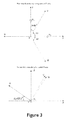
- a major advantage is that the gravitational field is experienced equally by each sensor in the 3-dimensional Galperin configuration - figure 3 .
- the Cartesian and Galperin configurations can be constructed using many spatial arrangements of sensor elements.
- the sensor elements can, for instance, be stacked one above the other to provide a vertical distribution - figures 4 and 5 .
- the sensors may be bi-directional microphones, for example comprising two back-to-back microphones each capable of giving a generally cardioid response.
- the senor of choice In air the sensor of choice will be a microphone, while in water to sensor of choice will be a hydrophone.
- the term sensor will henceforth be used to mean either microphone or hydrophone.
- Each sensor is designed to record a bi-directional response. These sensors could directly measure the bi-directional response of an acoustic wavefield or they could be composed of sub-sensor elements that when combined provide a bi-directional measurement.
- Figure 6 shows how omnidirectional and bidirectional microphone responses can be constructed from cardioid microphone sensor elements. The present invention uses this approach to the construction of omnidirectional and bi-directional hydrophones for use in water.
- omnidirectional and bi-directional sensors from cardioid elements requires those elements to be extremely well matched in terms of their sensitivity, directional and frequency responses.
- Matched cardioid elements can be found, for example, by characterising the elements very carefully and then combining only those elements with well matched characteristics.
- An alternative approach is to characterise the cardioid sensor elements through calibration testing and then apply sensitivity, directivity and frequency corrections to each element in software so that their output characteristics are matched before their data are combined to construct omnidirectional and bidirectional sensors.
- the 1, 2 or 3-component sensor can be augmented by the addition of at least one additional bidirectional sensor aligned in such a way that its response is a vector sum of the orthogonal components measured by either the Cartesian or Galperin configurations.
- This additional sensor or sensors can provide a check that the calibration approaches applied to the orthogonal measurements are stable, because a vector sum of the orthogonal components should match the measurement from the additional sensor. Similarly, if one of the orthogonal sensors fails, then its component can be calculated from the remaining orthogonal sensor measurements and the additional non-orthogonal measurement.
- the 2 or 3-dimensional sensor's measurement vector can be orientated using calibration acoustic pings activated from known positions. The measured vector and then be rotated to a desired reference frame by vector rotation. Alternatively, the sensors orientation can be surveyed. If the sensor is mounted on a vehicle, then its instantaneous vector orientation needs to be measured using a combination of inclinometers, accelerometers, magnetometers and gyroscopes. These auxiliary measurements provide roll, pitch and yaw information, so that the vector of the acoustic sensor measurements can be rotated to a desired orientation.
- the 2 or 3-dimensional acoustic sensors provide both timing and direction information relating to the incident acoustic wavefield
- multiple 2 or 3-dimensional sensors can be distributed in either an areal (2D) or a spatial (3D) array with an inter-sensor separation of less than I m, so that arrival time differences can also be measured that will improve the accuracy with which the acoustic wavefield can be characterised.
- Multiple 2 or 3-dimensional acoustic sensors can also be located with some distance between measurement locations, greater than 1m, along a baseline at positions A and B, and separated by a distance S so that their combined data can be triangulated to locate the source of the incident acoustic signal and its range D - figure 7 .
- the 2 or 3-dimensional measurements that form part of this invention require only two positions to be occupied for accurate acoustic source origins to be identified using the method of triangulation, because the arrival time and propagation direction of the acoustic wavefield are measured at each sensor location.
- the use of scalar measurements as described in the prior art require three locations to be occupied by sensors to determine from which side of the principal baseline the acoustic signal originates when using the triangulation method.
- the cardioid response of a sensor can be altered through either the use of horns or by forming a curved sensor element.
- the objective of this part of the invention is to alter the directivity response and have each sensor sub-element measure one half of the bi-directional response as shown in figure 6 (instead of a cardioid response), so that each sub-element is only sensitive to the direction towards which it is facing and its directivity response varies as the cosine of the angle of incidence.
- the desired bi-directional sensor response can then be constructed by simple combination of sensor elements that are orientated 180° from one another.
- the standard bi-directional response with a directivity proportional to the cosine of the angle of incidence is ideal, so long as its directivity response has a single lobe in each hemisphere and its directivity response is known, then multi-component measurements can be combined to describe the vector of the incident acoustic wavefield.
- the sensor could have a directional sensitivity proportional to the cosine 2 of the angle of incidence.
- polarisation filters can be applied to the data to enhance the sensitivity of the measurement in required directions and to reduce or nullify the sensitivity of the measurement in undesired directions.
- FIGS 8 to 11 show an acoustic detector generally indicated 50.
- the detector 50 comprises a base 55, a pair of support legs 60, 65 and a sensor head 70.
- the head 70 is generally spherical and is hollow.
- the shell has six sensor apertures 75a, 75b, 80a, 80b, 85a, 85b, being three pairs (the members of each pair being opposite each other) positioned to define three orthogonal components: X, Y, Z in a Cartesian array.
- Acoustic sensors can be mounted in each of the apertures.
- cardioid response microphones with well matched responses
- Figures 12 to 14 show a detector 150 formed according to a further embodiment.
- the detector 150 is similar to the detector 50 and includes a spherical head 170 with six apertures 175a, 175b, 180a, 180b, 185a, 185b arranged in three pairs; members of each pair being opposite each other and the three pairs being orthogonal to each other.
- the head is mounted on a U-section stem 190.
- the orthogonal components G 1 , G 2 , G 3 are arranged in a Galperin array, in use providing for a three-component acoustic wavefield measurement.
- Space/High altitude 3 component cosmic ray detector Data logging (3D array in a 'pig') Water Mains detect leaks Sewers listen for high flow rates - somehow detect blockages detect cave-ins Gas Pipes listen for leaks Oils wells Scan the bore hole for leaks Security Border/Perimeter Protection Detect selected noises - track them Footfalls, Engine/Wheel/Tracked vehicles Gates opening and closing noises Person detection - people smuggling etc. House/Garden protection Link to home PCor 'Internet of Things' Pre-gunshot noises - cocking of a rifle etc. school protection etc. Voice monitoring Track people based on the content of speech - keywords, Stress levels in voices Airports, Shoppingcentres and train stations.
- a further embodiment (not shown) relates to directional sensing of acoustic events and in particular to a sniper detection system.
- a four component microphone is provided that delivers highly accurate position information relating to the source of a sound. Detection of the muzzle blast and the shock wave enables trajectory information to be established in support of accurately determining the location of the acoustic source.
Landscapes
- Engineering & Computer Science (AREA)
- Remote Sensing (AREA)
- Physics & Mathematics (AREA)
- General Physics & Mathematics (AREA)
- Radar, Positioning & Navigation (AREA)
- Life Sciences & Earth Sciences (AREA)
- Computer Networks & Wireless Communication (AREA)
- Acoustics & Sound (AREA)
- Environmental & Geological Engineering (AREA)
- Geology (AREA)
- General Life Sciences & Earth Sciences (AREA)
- Geophysics (AREA)
- Measurement Of Velocity Or Position Using Acoustic Or Ultrasonic Waves (AREA)
Applications Claiming Priority (2)
| Application Number | Priority Date | Filing Date | Title |
|---|---|---|---|
| GBGB1417583.0A GB201417583D0 (en) | 2014-10-06 | 2014-10-06 | An acoustic detection system |
| GBGB1514557.6A GB201514557D0 (en) | 2015-08-15 | 2015-08-15 | An acoustic detection system |
Publications (2)
| Publication Number | Publication Date |
|---|---|
| EP3012651A2 true EP3012651A2 (fr) | 2016-04-27 |
| EP3012651A3 EP3012651A3 (fr) | 2016-07-27 |
Family
ID=54207380
Family Applications (1)
| Application Number | Title | Priority Date | Filing Date |
|---|---|---|---|
| EP15187029.2A Withdrawn EP3012651A3 (fr) | 2014-10-06 | 2015-09-28 | Système de détection acoustique |
Country Status (3)
| Country | Link |
|---|---|
| US (1) | US20160216363A1 (fr) |
| EP (1) | EP3012651A3 (fr) |
| GB (1) | GB2531161A (fr) |
Cited By (2)
| Publication number | Priority date | Publication date | Assignee | Title |
|---|---|---|---|---|
| EP3525478A1 (fr) * | 2018-02-08 | 2019-08-14 | Audio-Technica Corporation | Dispositif de microphone |
| US20200333429A1 (en) * | 2017-12-29 | 2020-10-22 | Ubicquia Iq Llc | Sonic pole position triangulation in a lighting system |
Families Citing this family (19)
| Publication number | Priority date | Publication date | Assignee | Title |
|---|---|---|---|---|
| US9213078B1 (en) * | 2014-05-31 | 2015-12-15 | The Boeing Company | Noise source decomposition system and method using an adaptable aperture phased array |
| US10082560B2 (en) * | 2014-10-17 | 2018-09-25 | Pgs Geophysical As | Sensor receiver nulls and null steering |
| US10042038B1 (en) * | 2015-09-01 | 2018-08-07 | Digimarc Corporation | Mobile devices and methods employing acoustic vector sensors |
| US10060578B2 (en) * | 2016-05-16 | 2018-08-28 | International Business Machines Corporation | Automated gas detection and reporting system |
| US10394239B2 (en) | 2017-04-04 | 2019-08-27 | At&T Intellectual Property I, L.P. | Acoustic monitoring system |
| FR3078401B1 (fr) * | 2018-02-26 | 2020-02-07 | Airbus Helicopters | Procede de surveillance et de detection de la formation d'une degradation dans au moins une piece mobile d'un mecanisme tournant et systeme associe |
| EP3844044B1 (fr) * | 2018-08-30 | 2024-04-03 | Voestalpine Signaling USA Inc. | Procédé mis en oeuvre par ordinateur pour un système de surveillance acoustique pour véhicules ferroviaires |
| US10761176B1 (en) | 2018-10-16 | 2020-09-01 | Honeywell International Inc. | Systems and methods for distance independent differential signature detection |
| US11158174B2 (en) | 2019-07-12 | 2021-10-26 | Carrier Corporation | Security system with distributed audio and video sources |
| US20210165426A1 (en) * | 2019-12-02 | 2021-06-03 | Here Global B.V. | Method and apparatus for determining aerial routes based on mapping drone disabling instruments |
| US11796562B2 (en) * | 2020-05-29 | 2023-10-24 | Aivs Inc. | Acoustic intensity sensor using a MEMS triaxial accelerometer and MEMS microphones |
| WO2022075035A1 (fr) * | 2020-10-05 | 2022-04-14 | 株式会社オーディオテクニカ | Dispositif de localisation de source sonore, procédé de localisation de source sonore et programme |
| US20220148411A1 (en) * | 2020-11-06 | 2022-05-12 | Ford Global Technologies, Llc | Collective anomaly detection systems and methods |
| US11778712B2 (en) * | 2020-11-17 | 2023-10-03 | Energy Control Services Llc | System and method for analysis of lighting control events |
| CN113687305B (zh) * | 2021-07-26 | 2024-11-29 | 浙江大华技术股份有限公司 | 声源方位的定位方法、装置、设备及计算机可读存储介质 |
| FR3131640B1 (fr) * | 2021-12-31 | 2024-05-10 | Observatoire Regional Du Bruit En Idf | Systeme de localisation d’une source sonore, notamment de nuisances sonores provenant de vehicules |
| WO2023212156A1 (fr) * | 2022-04-28 | 2023-11-02 | Aivs Inc. | Capteur de vecteur de formeur de faisceaux acoustiques à base d'accéléromètres à microphone de mems colocalisé |
| CN115352438B (zh) * | 2022-08-10 | 2025-03-21 | 东风商用车有限公司 | 井下矿区的安全保护方法、装置、设备及可读存储介质 |
| CN116592987B (zh) * | 2023-07-17 | 2023-09-26 | 中国特种设备检测研究院 | 面内全向波动场矢量探测方法及装置 |
Family Cites Families (9)
| Publication number | Priority date | Publication date | Assignee | Title |
|---|---|---|---|---|
| US4173748A (en) * | 1978-08-03 | 1979-11-06 | Sanders Associates, Inc. | Acoustic transducing system |
| US5010531A (en) * | 1989-10-02 | 1991-04-23 | Western Atlas International, Inc. | Three-dimensional geophone |
| US6041127A (en) * | 1997-04-03 | 2000-03-21 | Lucent Technologies Inc. | Steerable and variable first-order differential microphone array |
| DE19915036C2 (de) * | 1999-04-01 | 2003-09-18 | Adnr Technology Services Gmbh | Verfahren zum Auffinden, zur Identifizierung der Art und der geometrischen Abmessungen von Kohlenwasserstoffvorkommen |
| CN101556335A (zh) * | 2007-11-20 | 2009-10-14 | 中国船舶重工集团公司第七一○研究所 | 一种三分量海洋地震波检测传感器 |
| US9304221B2 (en) * | 2011-04-04 | 2016-04-05 | Westerngeco L.L.C. | Determining an indication of wavefield velocity |
| US9973848B2 (en) * | 2011-06-21 | 2018-05-15 | Amazon Technologies, Inc. | Signal-enhancing beamforming in an augmented reality environment |
| EP2747449B1 (fr) * | 2012-12-20 | 2016-03-30 | Harman Becker Automotive Systems GmbH | Système de capture sonore |
| EP2960679B1 (fr) * | 2013-02-01 | 2022-03-16 | WesternGeco, L.L.C. | Calcul de données de rotation à l'aide d'un gradient de données de translation |
-
2015
- 2015-09-28 EP EP15187029.2A patent/EP3012651A3/fr not_active Withdrawn
- 2015-09-28 GB GB1517055.8A patent/GB2531161A/en not_active Withdrawn
- 2015-10-08 US US14/878,835 patent/US20160216363A1/en not_active Abandoned
Cited By (4)
| Publication number | Priority date | Publication date | Assignee | Title |
|---|---|---|---|---|
| US20200333429A1 (en) * | 2017-12-29 | 2020-10-22 | Ubicquia Iq Llc | Sonic pole position triangulation in a lighting system |
| EP3525478A1 (fr) * | 2018-02-08 | 2019-08-14 | Audio-Technica Corporation | Dispositif de microphone |
| US10536762B2 (en) | 2018-02-08 | 2020-01-14 | Audio-Technica Corporation | Microphone device and case for microphone device |
| US10951969B2 (en) | 2018-02-08 | 2021-03-16 | Audio-Technica Corporation | Case for microphone device |
Also Published As
| Publication number | Publication date |
|---|---|
| EP3012651A3 (fr) | 2016-07-27 |
| GB2531161A (en) | 2016-04-13 |
| US20160216363A1 (en) | 2016-07-28 |
| GB201517055D0 (en) | 2015-11-11 |
Similar Documents
| Publication | Publication Date | Title |
|---|---|---|
| EP3012651A2 (fr) | Système de détection acoustique | |
| US6178141B1 (en) | Acoustic counter-sniper system | |
| US6536553B1 (en) | Method and apparatus using acoustic sensor for sub-surface object detection and visualization | |
| Jolly et al. | Capturing the acoustic radiation pattern of strombolian eruptions using infrasound sensors aboard a tethered aerostat, Yasur volcano, Vanuatu | |
| Garcés et al. | Infrasonic tremor observed at Kīlauea Volcano, Hawai'i | |
| Duckworth et al. | OptaSense distributed acoustic and seismic sensing using COTS fiber optic cables for infrastructure protection and counter terrorism | |
| Zhao et al. | Model space exploration for determining landslide source history from long-period seismic data | |
| Contrucci et al. | Aseismic mining subsidence in an abandoned mine: influence factors and consequences for post-mining risk management | |
| Hashimov et al. | Detection of Unobserved Ground Targets by Use of Seismic Location Stations | |
| EP3635441B1 (fr) | Procédé d'acquisition d'un ensemble de données sismiques sur une région d'intérêt | |
| Park et al. | Seismo-acoustic characterisation of the 2018 Ambae (Manaro Voui) eruption, Vanuatu | |
| RU2436134C1 (ru) | Способ оперативного исследования атмосферы, земной поверхности и океана | |
| RU2189051C2 (ru) | Способ обнаружения ионосферного возмущения и определения местоположения его источника | |
| Pasyanos et al. | Advances in geophysical forensic event monitoring | |
| Duckworth et al. | Optasense® distributed acoustic and seismic sensing performance for multi-threat, multi-environment border monitoring | |
| Nippress et al. | Seismoacoustic analysis of the 7 July 2011 Abadan, Turkmenistan, explosions | |
| Bird et al. | Topographically scattered infrasound waves observed on microbarometer arrays in the lower stratosphere | |
| US20090126464A1 (en) | Acoustic Detector | |
| Bonnin et al. | Short‐Range Recordings of Shallow Underwater Explosions with Short‐Period and Broadband Seismometers in the Bay of Hyères, France | |
| Sheetz | Advancements in buried mine detection using seismic sonar | |
| Che et al. | Generation of infrasound waves at sites of underground mine collapses | |
| Reiff | Acoustic source localization and cueing from an aerostat during the NATO SET-093 field experiment | |
| Assaad | Surface geophysical petroleum exploration methods | |
| US3922635A (en) | Method of locating and destroying water borne targets | |
| Khristoforov | About the control of the underwater and above water nuclear explosions by hydroacoustic methods |
Legal Events
| Date | Code | Title | Description |
|---|---|---|---|
| PUAI | Public reference made under article 153(3) epc to a published international application that has entered the european phase |
Free format text: ORIGINAL CODE: 0009012 |
|
| AK | Designated contracting states |
Kind code of ref document: A2 Designated state(s): AL AT BE BG CH CY CZ DE DK EE ES FI FR GB GR HR HU IE IS IT LI LT LU LV MC MK MT NL NO PL PT RO RS SE SI SK SM TR |
|
| AX | Request for extension of the european patent |
Extension state: BA ME |
|
| PUAL | Search report despatched |
Free format text: ORIGINAL CODE: 0009013 |
|
| AK | Designated contracting states |
Kind code of ref document: A3 Designated state(s): AL AT BE BG CH CY CZ DE DK EE ES FI FR GB GR HR HU IE IS IT LI LT LU LV MC MK MT NL NO PL PT RO RS SE SI SK SM TR |
|
| AX | Request for extension of the european patent |
Extension state: BA ME |
|
| RIC1 | Information provided on ipc code assigned before grant |
Ipc: G01S 5/18 20060101ALI20160623BHEP Ipc: G01S 5/20 20060101ALI20160623BHEP Ipc: G01S 3/801 20060101AFI20160623BHEP |
|
| STAA | Information on the status of an ep patent application or granted ep patent |
Free format text: STATUS: REQUEST FOR EXAMINATION WAS MADE |
|
| 17P | Request for examination filed |
Effective date: 20161114 |
|
| RBV | Designated contracting states (corrected) |
Designated state(s): AL AT BE BG CH CY CZ DE DK EE ES FI FR GB GR HR HU IE IS IT LI LT LU LV MC MK MT NL NO PL PT RO RS SE SI SK SM TR |
|
| STAA | Information on the status of an ep patent application or granted ep patent |
Free format text: STATUS: THE APPLICATION HAS BEEN WITHDRAWN |
|
| 18W | Application withdrawn |
Effective date: 20170928 |