EP3012921B1 - Connecteur étanche à l'eau et équipement électronique - Google Patents
Connecteur étanche à l'eau et équipement électronique Download PDFInfo
- Publication number
- EP3012921B1 EP3012921B1 EP14813270.7A EP14813270A EP3012921B1 EP 3012921 B1 EP3012921 B1 EP 3012921B1 EP 14813270 A EP14813270 A EP 14813270A EP 3012921 B1 EP3012921 B1 EP 3012921B1
- Authority
- EP
- European Patent Office
- Prior art keywords
- shell
- providing
- support
- sealing member
- waterproof connector
- Prior art date
- Legal status (The legal status is an assumption and is not a legal conclusion. Google has not performed a legal analysis and makes no representation as to the accuracy of the status listed.)
- Active
Links
Images


Classifications
-
- H—ELECTRICITY
- H01—ELECTRIC ELEMENTS
- H01R—ELECTRICALLY-CONDUCTIVE CONNECTIONS; STRUCTURAL ASSOCIATIONS OF A PLURALITY OF MUTUALLY-INSULATED ELECTRICAL CONNECTING ELEMENTS; COUPLING DEVICES; CURRENT COLLECTORS
- H01R13/00—Details of coupling devices of the kinds covered by groups H01R12/70 or H01R24/00 - H01R33/00
- H01R13/46—Bases; Cases
- H01R13/52—Dustproof, splashproof, drip-proof, waterproof, or flameproof cases
- H01R13/5219—Sealing means between coupling parts, e.g. interfacial seal
-
- H—ELECTRICITY
- H01—ELECTRIC ELEMENTS
- H01R—ELECTRICALLY-CONDUCTIVE CONNECTIONS; STRUCTURAL ASSOCIATIONS OF A PLURALITY OF MUTUALLY-INSULATED ELECTRICAL CONNECTING ELEMENTS; COUPLING DEVICES; CURRENT COLLECTORS
- H01R13/00—Details of coupling devices of the kinds covered by groups H01R12/70 or H01R24/00 - H01R33/00
- H01R13/46—Bases; Cases
- H01R13/52—Dustproof, splashproof, drip-proof, waterproof, or flameproof cases
- H01R13/5202—Sealing means between parts of housing or between housing part and a wall, e.g. sealing rings
-
- H—ELECTRICITY
- H01—ELECTRIC ELEMENTS
- H01R—ELECTRICALLY-CONDUCTIVE CONNECTIONS; STRUCTURAL ASSOCIATIONS OF A PLURALITY OF MUTUALLY-INSULATED ELECTRICAL CONNECTING ELEMENTS; COUPLING DEVICES; CURRENT COLLECTORS
- H01R13/00—Details of coupling devices of the kinds covered by groups H01R12/70 or H01R24/00 - H01R33/00
- H01R13/73—Means for mounting coupling parts to apparatus or structures, e.g. to a wall
-
- H—ELECTRICITY
- H01—ELECTRIC ELEMENTS
- H01R—ELECTRICALLY-CONDUCTIVE CONNECTIONS; STRUCTURAL ASSOCIATIONS OF A PLURALITY OF MUTUALLY-INSULATED ELECTRICAL CONNECTING ELEMENTS; COUPLING DEVICES; CURRENT COLLECTORS
- H01R12/00—Structural associations of a plurality of mutually-insulated electrical connecting elements, specially adapted for printed circuits, e.g. printed circuit boards [PCB], flat or ribbon cables, or like generally planar structures, e.g. terminal strips, terminal blocks; Coupling devices specially adapted for printed circuits, flat or ribbon cables, or like generally planar structures; Terminals specially adapted for contact with, or insertion into, printed circuits, flat or ribbon cables, or like generally planar structures
- H01R12/70—Coupling devices
- H01R12/71—Coupling devices for rigid printing circuits or like structures
- H01R12/72—Coupling devices for rigid printing circuits or like structures coupling with the edge of the rigid printed circuits or like structures
- H01R12/722—Coupling devices for rigid printing circuits or like structures coupling with the edge of the rigid printed circuits or like structures coupling devices mounted on the edge of the printed circuits
- H01R12/724—Coupling devices for rigid printing circuits or like structures coupling with the edge of the rigid printed circuits or like structures coupling devices mounted on the edge of the printed circuits containing contact members forming a right angle
-
- H—ELECTRICITY
- H01—ELECTRIC ELEMENTS
- H01R—ELECTRICALLY-CONDUCTIVE CONNECTIONS; STRUCTURAL ASSOCIATIONS OF A PLURALITY OF MUTUALLY-INSULATED ELECTRICAL CONNECTING ELEMENTS; COUPLING DEVICES; CURRENT COLLECTORS
- H01R13/00—Details of coupling devices of the kinds covered by groups H01R12/70 or H01R24/00 - H01R33/00
- H01R13/40—Securing contact members in or to a base or case; Insulating of contact members
- H01R13/405—Securing in non-demountable manner, e.g. moulding, riveting
-
- H—ELECTRICITY
- H01—ELECTRIC ELEMENTS
- H01R—ELECTRICALLY-CONDUCTIVE CONNECTIONS; STRUCTURAL ASSOCIATIONS OF A PLURALITY OF MUTUALLY-INSULATED ELECTRICAL CONNECTING ELEMENTS; COUPLING DEVICES; CURRENT COLLECTORS
- H01R13/00—Details of coupling devices of the kinds covered by groups H01R12/70 or H01R24/00 - H01R33/00
- H01R13/62—Means for facilitating engagement or disengagement of coupling parts or for holding them in engagement
- H01R13/627—Snap or like fastening
- H01R13/6271—Latching means integral with the housing
-
- H—ELECTRICITY
- H01—ELECTRIC ELEMENTS
- H01R—ELECTRICALLY-CONDUCTIVE CONNECTIONS; STRUCTURAL ASSOCIATIONS OF A PLURALITY OF MUTUALLY-INSULATED ELECTRICAL CONNECTING ELEMENTS; COUPLING DEVICES; CURRENT COLLECTORS
- H01R13/00—Details of coupling devices of the kinds covered by groups H01R12/70 or H01R24/00 - H01R33/00
- H01R13/62—Means for facilitating engagement or disengagement of coupling parts or for holding them in engagement
- H01R13/627—Snap or like fastening
- H01R13/6275—Latching arms not integral with the housing
-
- H—ELECTRICITY
- H01—ELECTRIC ELEMENTS
- H01R—ELECTRICALLY-CONDUCTIVE CONNECTIONS; STRUCTURAL ASSOCIATIONS OF A PLURALITY OF MUTUALLY-INSULATED ELECTRICAL CONNECTING ELEMENTS; COUPLING DEVICES; CURRENT COLLECTORS
- H01R24/00—Two-part coupling devices, or either of their cooperating parts, characterised by their overall structure
- H01R24/60—Contacts spaced along planar side wall transverse to longitudinal axis of engagement
- H01R24/62—Sliding engagements with one side only, e.g. modular jack coupling devices
Definitions
- This invention relates to a method of manufacturing a waterproof connector.
- Japanese Patent Application Publication No. 2009-176734 describes a conventional waterproof connector having a waterproof function for electronic equipment.
- This waterproof connector is formed by providing a contact terminal in a resin housing by insert molding, attaching a shell to the resin housing by fitting a rear end portion of the shell to a front end portion of the housing from outside, and fitting a flange-like sealing member in a connection groove formed in the outer periphery of the resin housing.
- the sealing member has an outer periphery provided with a groove part.
- a bottom case and a top case to accommodate the waterproof connector therein each have a protrusion inserted tightly in the groove part, thereby forming a watertight structure.
- CN 102 820 579 discloses an electrical connector and a manufacturing method of the electrical connector, relating to the preamble of claim 1.
- the electrical connector comprises an insulating body, a plurality of conductive terminals and a metal shell, wherein the conductive terminals are fixedly arranged in the insulating body; and the metal shell covers the insulating body.
- US 2012/108095 discloses a waterproof connector, including an inner insulating housing, a plurality of electrical contacts, an inner metal shell, a sealing plate, an outer insulating housing, an outer metal shell and a waterproof rubber ring.
- the inner metal shell is pressed to form a plurality of holding blocks and two holes.
- the sealing plate includes a connecting plate and two closing plates for covering the corresponding hole.
- the outer insulating housing is integrally formed with the inner insulating housing, the electrical contacts, the inner metal shell and the sealing plate by insert molding.
- the waterproof rubber ring encompasses a front end of the inner metal shell. The outer insulating housing can seal off the gaps between the sealing plate and the inner metal shell, and between the inner insulating housing and the inner metal shell.
- the aforementioned prior art waterproof connector is formed by attaching the shell to the resin housing by fitting the rear end portion of the shell to the front end portion of the housing from outside and locating the sealing member on the resin housing in a position behind the shell.
- the length of the waterproof connector is increased to increase an area taken up by the waterproof connector.
- the shell of the aforementioned prior art waterproof connector is prepared by forming a metal plate into a plate-like member of a designated shape by press molding, rounding the plate-like member, and connecting opposite end portions of the plate-like member so as to make a fit therebetween. This produces a seam extending in the entire length of a direction where a plug is to be inserted.
- the shell with this seam is likely to start to fracture at the seam or a vicinity thereof if a plug inserted in the connector is pried strongly or prying force is applied to the plug many times, causing a problem of insufficient strength and durability.
- This invention has been suggested in view of the aforementioned problem. It is an aim of this invention to provide a waterproof connector and electronic equipment capable of reducing an area taken up by the connector while ensuring waterproof performance, increasing an available area inside the electronic equipment, achieving layout design of the electronic equipment more freely, and contributing to size reduction of the electronic equipment. It is another aim of this invention to provide a waterproof connector and electronic equipment capable of increasing the strength and durability of a shell dramatically.
- a waterproof connector manufactured by a method according to an embodiment of the present invention includes: a shell of a seamless and substantially tubular shape, the shell being made of metal; a resin support accommodated in a wall pattern in the shell; a contact terminal supported by the support; and a sealing member provided around an outer periphery of the shell.
- the support supporting the contact terminal is accommodated in the seamless shell and the sealing member is provided around the outer periphery of the shell.
- this structure does not require a resin housing outside the shell to be provided for preventing water from entering through a seam. This can make the connector thinner by the thickness of the resin housing.
- an area taken up by the connector can be reduced to increase an available area inside electronic equipment, thereby achieving layout design of the electronic equipment more freely and contributing to size reduction of the electronic equipment.
- Eliminating the need of providing the resin housing outside or behind the shell makes a resin material for the resin housing unnecessary. Thus, manufacturing cost can be reduced.
- the seamless shell has no seam that is likely to cause fracture if a plug inserted in the connector is pried strongly or prying force is applied to the plug many times. This can increase the strength and durability of the shell dramatically.
- the method comprises providing the shell with a stepped part abutting on the sealing member and formed in a peripheral pattern.
- the sealing member can be located in and attached to a designated position on the outer periphery of the shell and can be attached to this designated position stably.
- the method comprises providing the shell with a non-through recess formed so as to bulge outward.
- the non-through recess allows engagement of a hook of a plug.
- This structure allows engagement of a hook of a plug inserted in the waterproof connector, so that the plug can be inserted in the waterproof connector stably with required attachment strength.
- the non-through recess not penetrating the shell is provided as a part where the hook of the plug can be engaged. This can increase the strength and durability of the shell further.
- the step of providing the shell comprises forming a non-perforated surface extending at least in an area of the shell ahead of a front surface of the support.
- the shell is formed of the non-perforated surface with no perforated part extending at least in the area of the shell ahead of the front surface of the support. This can increase the strength and durability of the shell further. Unlike in the case where a through hole is formed and water flows through this through hole as a path, forming the shell using the non-perforated surface removes the occurrence of such a water flow, thereby preventing entry of water into a hard-to-dry place. Further, the sealing member is attached to an anteroposterior position in a direction where a plug is to be inserted that can be determined with a considerably increased degree of freedom.
- the method comprises providing the shell with an engagement hole that allows engagement of a hook of a plug and providing the sealing member around the outer periphery of the shell and behind the engagement hole.
- This structure having the engagement hole in the shell can be achieved only by forming the engagement hole in an appropriate part independently of a different part. This increases a degree of freedom of the shape and provides responsiveness to customization easily. Thus, various requests for the shape of the shell can be responded flexibly while the strength and durability of the shell are increased. Further, the size of the shell can be reduced by reducing the height of the shell in a thickness direction, for example, while the strength and durability of the shell are increased. Additionally, providing the sealing member around the outer periphery of the shell and behind the engagement hole prevents entry of water through the engagement hole. This makes it possible to ensure waterproof performance with the sealing member without the need of providing a resin housing outside the shell.
- the method comprises filling a rear-side receiving part like a recess with a sealing material.
- the receiving part is formed of the shell and the support.
- This structure can reliably prevent entry of water from the inside of the shell into a place adjacent to a circuit board of electronic equipment independently of a condition of the support accommodated in the shell.
- the method comprises fitting the support in the shell in a watertight manner wherein the shell includes a rear section provided with an abutting part abutting on a rear surface of the support.
- a watertight structure formed by the shell and the support can prevent entry of water from the inside of the shell into a place adjacent to the circuit board of the electronic equipment reliably.
- the abutting contact of the rear surface of the support with the abutting part stabilizes a fitting condition of the support while contributing to retention of the support.
- This invention is capable of reducing an area taken up by the connector while ensuring waterproof performance, increasing an available area inside the electronic equipment, achieving layout design of the electronic equipment more freely, and contributing to size reduction of the electronic equipment.
- This invention is also capable of increasing the strength and durability of the shell dramatically.
- a waterproof connector 1 manufactured according to the present invention is used in mobile electronic equipment, etc. such as multifunctional mobile phones, multifunctional mobile information terminals, and mobile audio players.
- the waterproof connector 1 conforms to a standard such as the micro-USB standard.
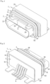
- the waterproof connector 1 includes a shell 2 of a seamless and substantially tubular shape, a resin support 3 accommodated in a wall pattern in the shell 2, contact terminals 4 supported by the support 3, and a sealing member 5 provided around the outer periphery of the shell 2.
- the waterproof connector 1 is attached to electronic equipment by being accommodated in a case of the electronic equipment.
- the shell 2 is formed by drawing press work on a metal flat plate.
- the shell 2 is formed into a substantially rectangular tubular shape without a seam.
- the shell 2 has a stepped part formed in a direction where a plug is to be inserted.
- the shell 2 has a stepped part 24 formed on the upper surface of the shell 2 so as to bulge outward and extend from a front section 21 adjacent to a place where the plug is to be inserted to an intermediate section 22 thicker than the front section 21.
- the shell 2 has a stepped part 25 formed on the peripheral surface of the shell 2 so as to bulge outward in a peripheral pattern and extend from the intermediate section 22 to a rear section 23 thicker than and wider than the intermediate section 22.
- the sealing member 5 described later abuts in a peripheral pattern on the stepped part 25 of the peripheral pattern.
- the upper surface of the shell 2 is provided with non-through recesses 26 formed in two places so as to bulge outward and protrude forward from the stepped part 24.
- the non-through recesses 26 are each formed into a recessed shape that allows engagement of a claw-shaped hook of a plug such as a micro-USB plug when this plug is inserted in the shell 2.
- the non-through recess 26 is formed so as to bulge outward in a step of the drawing press work on the metal flat plate for forming the shell 2.
- the shell 2 is formed of a non-perforated surface extending at least in an area of the shell 2 ahead of a front surface 311 of the support 33 including the front section 21 adjacent to the place where a plug is to be inserted and the intermediate section 22, for example.
- the shell 2 is formed of a non-perforated surface with no perforated part extending through the front section 21, the intermediate section 22, and the rear section 23 entirely.
- the support 3 is made of insulating hard resin.
- the support 3 is formed in a wall pattern so as to block the back of the shell 2.
- the support 3 is inserted and fitted in the rear section 23 of the shell 2 in a manner such that the front surface 311 of body 31 like a substantially rectangular parallelepiped of the support 3 abuts on the inner surface of the stepped part 25.
- the contact terminals 4 are buried in a part of the support 3 by insert molding.
- the contact terminals 4 are attached to the support 3 so as to form a watertight structure by the insert molding. If a receiving part 61 is to be filled with a sealing material 62 described later, the contact terminals 4 can be installed on the support 3 without forming a watertight structure.
- the contact terminals 4 can be attached to the support 3 by being fitted and inserted in through holes in the support 3.
- the contact terminals 4 are each arranged along one side of a protruding part 32 of the support 3 protruding forward and introduced into the shell 2.
- the contact terminals 4 are each exposed in the shell 2 in a manner such that the contact terminal 4 can contact and can be electrically continuous with a contact of a plug. Further, the contact terminals 4 are pulled out of the body 31 from a rear side thereof and connected to a circuit board of the electronic equipment not shown in the drawings. Appropriate ones of the contact terminals 4 can be a power supply terminal and a ground terminal.
- the sealing member 5 is made of soft resin such as elastomer and formed like a ring of a substantially rectangular frame shape.
- the sealing member 5 has a body 51 substantially rectangular in cross section and a protruding strip 52 having a shape like a ridge in cross section protruding outward from the body 51.
- the sealing member 5 can be formed using an appropriate material that achieves sealing with a waterproof function. Not only the soft resin such as elastomer but also an O-ring or a water repelling member can be used for forming the sealing member 5.
- the sealing member 5 is made of the water repelling member
- the water repelling member may be a coating layer of a water repellent and the sealing member 5 can be configured in a manner such that a gap is formed between a case-side member such as the case of the electronic equipment and the water repelling member while the water repelling member does not abut on the case-side member.
- the sealing member 5 is fitted to the outer periphery of the intermediate section 22 in a manner such that one side surface of the body 51 abuts on an outer side surface of the stepped part 25.
- the sealing member 5 is fitted to the intermediate section 22 from outside and located in a fixed position.
- the sealing member 5 is fitted to the outer periphery of the intermediate section 22 having a planar peripheral surface.
- the sealing member 5 can be configured so as to extend in a peripheral pattern by forming a fitting groove into a peripheral pattern in the intermediate section 22 and fitting the sealing member 5 by fitting a protruding strip formed so as to protrude toward the inside of the sealing member 5 in this fitting groove, for example.
- the shell 2 is formed of a non-perforated surface with no perforated part extending through the front section 21, the intermediate section 22, and the rear section 23 entirely.
- the sealing member 5 can be attached in a position that can be determined arbitrarily in an anterior-posterior direction of the shell 2.
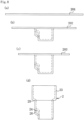
- the protruding strip 52 has a tip that abuts on a bottom case 11 and a top case 12 forming the case of the electronic equipment, for example, in a manner such that the tip is pressed with the bottom case 11 and the top case 12, thereby forming a watertight structure (see Figs. 5 to 7 ).
- 111 is an opening for plug insertion. In the illustration of the drawings, this opening 111 is provided at a side wall of the bottom case 11.
- the watertight structure may be formed by making a fit of the protruding strip 52 in a groove part of the bottom case 11 and a groove part of the top case 12.
- the watertight structure can be formed by pressing the sealing member 5 with the case indirectly.
- the watertight structure can be formed by making abutting contact of the sealing member 5 with a seal receiving member such as rubber provided to the bottom case 11 or the top case 12, or both of the bottom case 11 and the top case 12 so as to press the sealing member 5 with this seal receiving member.
- the rear section 23 of the shell 2 protrudes backward further than the rear surface of the body 31 of the support 3.
- the rear-side receiving part 61 like a recess formed of the protruding portion of the rear section 23 and the rear surface of the body 31 is filled with the sealing material 62 that is formed by pouring bond etc. and hardening the bond in the receiving part 61. Forming the sealing material 62 in the receiving part 61 makes it possible to more reliably prevent entry of water into a circuit board of the electronic equipment arranged adjacent to the rear surface of the support 3, for example. If the support 3 is to be accommodated in the shell 2 by fitting the support 3 in a watertight manner in the shell 2, pouring the sealing material 62 can be omitted.
- the support 3 can also be accommodated in the shell 2 by providing an abutting part such as a bent part same as a bent part 231a of a shell 2a according to a second embodiment described later to the rear section 23 and making abutting contact of the abutting part with the rear surface of the support 3.
- an abutting part such as a bent part same as a bent part 231a of a shell 2a according to a second embodiment described later to the rear section 23 and making abutting contact of the abutting part with the rear surface of the support 3.
- the waterproof connector 1 is formed by forming the shell 2 using drawing press work on a metal flat plate into an entirely seamless and substantially rectangular tubular shape with the stepped parts 24 and 25 and the non-through recess 26 bulging outward.
- the drawing press is performed in stages on a metal flat plate 201 to form respective patterns of the front section 21, the intermediate section 22, and the rear section 23. Further, while a pattern of the non-through recess 26 is formed so as to bulge outward, the metal flat plate 201 is processed into the shape of a work 202 and that of a work 203 sequentially. Further, an opening for plug insertion is punched to penetrate a tip, thereby forming the shell 2.
- the support 3 with the contact terminals 4 formed by insert molding is accommodated in the shell 2 so as to be fitted in the rear section 23.
- the sealing member 5 is fitted to the outer periphery of the intermediate section 22 in a manner such that a lateral portion of the sealing member 5 abuts on the stepped part 25, thereby obtaining the waterproof connector 1.
- the sealing material 62 is poured into and hardened in the rear-side receiving part 61 like a recess formed of the protruding portion of the rear section 23 and the rear surface of the body 31. This implements a waterproof process of preventing entry of water into the shell 2.
- the waterproof connector 1 is formed by accommodating the support 3 supporting the contact terminals 4 in the seamless shell 2. As a result, the length of the connector can be reduced while waterproof performance is ensured. Further, the absence of the resin housing outside the shell 2 can make the connector thinner by the thickness of the housing. This can reduce an area taken up by the connector to increase an available area inside the electronic equipment, thereby achieving layout design of the electronic equipment more freely and contributing to size reduction of the electronic equipment.
- Eliminating the need of providing a resin housing outside or behind the shell 2 makes a resin material for the resin housing unnecessary. Thus, manufacturing cost can be reduced.
- the shell 2 of a seamless and substantially tubular shape has no seam that is likely to cause fracture if a plug inserted in the connector is pried strongly or prying force is applied to the plug many times. This can increase the strength and durability of the shell 2 dramatically.
- the sealing member 5 can be located in and attached to a designated position on the outer periphery of the shell 2 and can be attached to this designated position stably.
- the presence of the non-through recess 26 of the shell 2 allows engagement of a hook of a plug inserted in the waterproof connector 1, so that the plug can be inserted in the waterproof connector 1 stably with required attachment strength.
- the non-through recess 26 not penetrating the shell 2 is provided as a part where the hook of the plug can be engaged. This can increase the strength and durability of the shell 2 further.
- the shell 2 is formed of a non-perforated surface with no perforated part. This can increase the strength and durability of the shell 2 further. Unlike in the case where a through hole is formed and water flows through this through hole as a path, forming the shell 2 using the non-perforated surface removes the occurrence of such a water flow, thereby preventing entry of water into a hard-to-dry place. Further, the sealing member 5 can be attached to any anteroposterior position of the shell 2 in the direction where a plug is to be inserted. Thus, the position where the sealing member 5 is to be attached can be determined with a considerably increased degree of freedom.
- the seamless shell 2 By using drawing press work on a metal flat plate to form the shell 2 into a seamless and substantially tubular shape, the seamless shell 2 of high strength and high durability can be manufactured easily at low cost. Additionally, if the non-through recess 26 is formed so as to bulge outward during this drawing press work, the seamless and substantially tubular shape of the shell 2 and the non-through recess 26 can be formed in the same drawing press step. This achieves efficient manufacture of high productivity. Further, forming the shell 2 as a shell without a through hole can eliminate punching work.
- a waterproof connector 1a manufactured with a method according this invention is also used in mobile electronic equipment, etc. such as multifunctional mobile phones, multifunctional mobile information terminals, and mobile audio players.
- the waterproof connector 1a conforms to a standard such as the micro-USB standard.
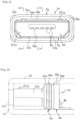
- the waterproof connector 1a also includes a shell 2a of a seamless and substantially tubular shape, a resin support 3a accommodated in a wall pattern in the shell 2a, contact terminals 4a supported by the support 3a, and a sealing member 5a provided around the outer periphery of the shell 2a.
- the waterproof connector 1a is attached to electronic equipment by being accommodated in a case of the electronic equipment.
- the shell 2a is formed by performing drawing press on a metal flat plate and forming an engagement hole using cutting and bending, for example.
- the shell 2a is formed into a substantially rectangular tubular shape without a seam.
- the shell 2a has a stepped part formed in a direction where a plug is to be inserted.
- the shell 2a has a stepped part 24a formed on the upper surface of the shell 2a so as to bulge outward and extend from a front section 21a longer than the front section 21 of the first embodiment in an anterior-posterior direction to an intermediate section 22a thicker than the front section 21a.
- the shell 2a has a stepped part 25a formed on the peripheral surface of the shell 2a so as to bulge outward in a peripheral pattern and extend from the intermediate section 22a to a rear section 23a thicker than and wider than the intermediate section 22a.
- the rear section 23a is formed to be shorter than the rear section 23 of the first embodiment.
- the sealing member 5a abuts in a peripheral pattern on the stepped part 25a of this peripheral pattern.
- the upper surface of the shell 2a is provided with long and thin engagement holes 27a formed in two places extending longitudinally in the anterior-posterior direction.
- Each of the engagement holes 27a has a front end provided with a cut and bent part 271a tilted upward and rearward.
- the cut and bent part 271a is formed as a cut and raised part in the shell 2a in a place near the front end of the engagement hole 27a.
- the engagement hole 27a and the cut and bent part 271a are formed in a manner such that a claw-shaped hook of a plug such as a micro-USB plug can be inserted in the engagement hole 27a and engaged with the cut and bent part 271a when this plug is inserted in the shell 2a.
- the support 3a is made of insulating hard resin and is formed in a wall pattern so as to block the back of the shell 2a.
- the support 3a is inserted and fitted in the intermediate section 22a of the shell 2a in a manner such that a front surface 311a of a body 31a like a substantially rectangular parallelepiped of the support 3a is located in the front section 21a and a stepped surface 312a on the upper surface of the body 31a abuts on the inner surface of the stepped part 24a.
- the support 3a is fitted to and accommodated in the shell 2a in a watertight manner.
- the support 3a accommodated in a designated position in the shell 2a has a rear surface 313a abutting on an abutting part provided to the rear section of the shell 2a.
- the rear surface 313a abuts on a bent part 231a formed by cutting the upper surface of the rear section 23a of the shell 2a and bending the cut inward.
- the bent part 231a includes a pair of right and left bent parts 231a abutting on the rear surface 313a.
- the abutting part such as the bent part 231a is omitted from the rear section 23a.
- the support 3a is fitted to and accommodated in the shell 2a so as to form a watertight structure or not to form a watertight structure and a receiving part like a recess formed of the rear section 23a of the shell 2a and the rear surface 313a of the support 3a is filled with a sealing material.
- the contact terminals 4a are buried in a part of the support 3a by insert molding.
- the contact terminals 4a are attached to the support 3a so as to form a watertight structure by the insert molding.
- the contact terminals 4a are each arranged along one side of a protruding part 32a of the support 3a protruding forward and introduced into the shell 2a.
- the contact terminals 4a are each exposed in the shell 2a in a manner such that the contact terminal 4a can contact and can be electrically continuous with a contact of a plug.
- the contact terminals 4 are pulled out of the body 31a from a rear side thereof and connected to a circuit board of the electronic equipment not shown in the drawings.
- Appropriate ones of the contact terminals 4a can be a power supply terminal and a ground terminal.
- the sealing member 5a is made of soft resin such as elastomer and formed like a ring of a substantially rectangular frame shape.
- the sealing member 5a has a body 51a substantially rectangular in cross section and a protruding strip 52a having a shape like a ridge in cross section protruding outward from the body 51a.
- the sealing member 5a can be formed using an appropriate material that achieves sealing with a waterproof function. Not only the soft resin such as elastomer but also an O-ring or a water repelling member can be used for forming the sealing member 5a, for example.
- the sealing member 5a is fitted to the outer periphery of the intermediate section 22a in a manner such that one side surface of the body 51a abuts on an outer side surface of the stepped part 25a.
- the sealing member 5a is fitted to the intermediate section 22a from outside and located in a fixed position.
- the sealing member 5a is fitted to the outer periphery of the intermediate section 22a having a planar peripheral surface.
- the sealing member 5a may alternatively be configured so as to extend in a peripheral pattern by forming a fitting groove into a peripheral pattern in the intermediate section 22a and fitting the sealing member 5a by fitting a protruding strip formed so as to protrude toward the inside of the sealing member 5a in this fitting groove, for example.
- the sealing member 5a can be attached in a position that can be determined arbitrarily in an anterior-posterior direction of the shell 2a as long as this position is behind the engagement hole 27a.
- the protruding strip 52a has a tip that abuts on a bottom case 11 and a top case 12 having an opening 111 for plug insertion and forming the case of the electronic equipment same as that of the first embodiment, for example, in a manner such that the tip is pressed with the bottom case 11 and the top case 12, thereby forming a watertight structure (see Figs. 12 to 14 ).
- the watertight structure may be formed by making a fit of the protruding strip 52a in a groove part of the bottom case 11 and a groove part of the top case 12. Instead of being formed by pressing the sealing member 5a with the case directly, the watertight structure can be formed by pressing the sealing member 5 with the case indirectly.
- the watertight structure can be formed by making abutting contact of the sealing member 5a with a seal receiving member such as rubber provided to the bottom case 11 or the top case 12, or both of the bottom case 11 and the top case 12 so as to press the sealing member 5a with this seal receiving member.
- a seal receiving member such as rubber provided to the bottom case 11 or the top case 12, or both of the bottom case 11 and the top case 12 so as to press the sealing member 5a with this seal receiving member.
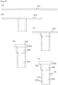
- drawing press is performed in stages on a metal flat plate 211 to form the metal flat plate 211 into the shape of a work 212 having a pattern of the front section 21a and the shape of a work 213 having a pattern of the intermediate section 22a sequentially. Then, the work 213 is brought to a condition including the front section 21a, the intermediate section 22a, and the rear section 23a. Further, an opening for plug insertion is punched to penetrate a tip, thereby obtaining a work 214 of the shell 2a of an entirely seamless and substantially tubular shape.
- cuts are formed on opposite sides of a position corresponding to the front end or vicinity thereof and a part between the cuts is raised by being bent, thereby forming the cut and bent part 271a and a front end neighboring region of the engagement hole 27a. Further, the front section 21a is punched in a position behind the front neighboring region of the engagement hole 27a, thereby forming a rear-side region of the engagement hole 27a, for example. In this way, the front section 21a is cut and bent to form the engagement hole 27a with the cut and bent part 271a.
- the support 3a with the contact terminals 4a formed by insert molding is fitted in the intermediate section 22a and accommodated in the shell 2a so as to form a watertight structure. Further, cutting and bending work is performed on a designated place of the rear section 23a to form the bent part 231a and the bent part 231a is made to abut on the rear surface 313a of the support 3a. Further, the sealing member 5a is fitted to the outer periphery of the intermediate section 22a in a manner such that a lateral portion of the sealing member 5a abuts on the stepped part 25a, thereby obtaining the waterproof connector 1a.
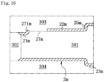
- Fig. 16 explains formation of a shell 2m of an entirely seamless and substantially tubular shape having a cut and bent part 271m and an engagement hole 27m by die casting in a process not according to the invention.
- the structure of the shell 2m is basically the same as that of the shell 2a.
- the shell 2m includes a front section 21m, an intermediate section 22m, a rear section 23m, a stepped part 25m, and the engagement hole 27m having the cut and bent part 271m formed on the upper surface of the front section 21m.
- the shell 2m does not include the stepped part 24a.
- the intermediate section 22m has an upper surface formed at a height substantially corresponding to the position of the upper end of the cut and bent part 271m.
- Die casting is performed with a mold 301 as a core located on a rear side, a mold 302 as a cavity located on a front side, and a mold 303 and a mold 304 as slide cores located by being moved slidingly from peripheral sides, thereby forming the shell 2m into a designated shape. Then, all the molds 301 to 304 are moved backward to extract the shell 2m.
- the upper surface of the intermediate section 22m is formed in the position substantially corresponding to the upper end of the cut and bent part 271m. This prevents the molds 301 and 302 from interfering with the shell 2m during the action of moving the molds 301 and 302 forward in preparation for the casting and the action of moving the molds 301 and 302 backward in preparation for the extraction after the casting.
- the support 3a with the contact terminals 4a formed by insert molding is fitted in the intermediate section 22a and accommodated in the shell 2m so as to form a watertight structure. Further, cutting and bending work is performed on a designated place of the rear section 23m to form a bent part and the bent part is made to abut on the rear surface 313a of the support 3a. Further, the sealing member 5a is fitted to the outer periphery of the intermediate section 22m in a manner such that a lateral portion of the sealing member 5a abuts on the stepped part 25m, thereby obtaining the waterproof connector 1a.
- the waterproof connector 1a is formed by accommodating the support 3a supporting the contact terminals 4a in the seamless shell 2a or 2m. As a result, the length of the connector can be reduced while waterproof performance is ensured. Further, the absence of a resin housing outside the shell 2a or 2m can make the connector thinner by the thickness of the housing. This can reduce an area taken up by the connector to increase an available area inside the electronic equipment, thereby achieving layout design of the electronic equipment more freely and contributing to size reduction of the electronic equipment.
- Eliminating the need of providing a resin housing outside or behind the shell 2a or 2m makes a resin material for the resin housing unnecessary. Thus, manufacturing cost can be reduced.
- the shell 2a or 2m of a seamless and substantially tubular shape has no seam that is likely to cause fracture if a plug inserted in the connector is pried strongly or prying force is applied to the plug many times. This can increase the strength and durability of the shell 2a or 2m dramatically.
- the structure of the shell 2a or 2m having the engagement hole 27a or 27m with the cut and bent part 271a or 271m can be achieved only by forming the engagement hole 27a or 27m with the cut and bent part 271a or 271m in an appropriate part independently of a different part. This increases a degree of freedom of a shape and provides responsiveness to customization easily. Thus, various requests for the shape of the shell 2a or 2m can be responded flexibly while the strength and durability of the shell 2a or 2m are increased. Further, the size of the shell 2a or 2m can be reduced by reducing the height of the shell 2a or 2m in a thickness direction, for example, while the strength and durability of the shell 2a or 2m are increased.
- sealing member 5a around the outer periphery of the shell 2a or 2m and behind the engagement hole 27a or 27m prevents entry of water through the engagement hole 27a or 27m. This makes it possible to ensure waterproof performance with the sealing member 5a without the need of providing a resin housing outside the shell 2a or 2m.
- the watertight structure formed by the shell 2a or 2m and the support 3a fitted to and accommodated in the shell 2a or 2m can prevent entry of water from the inside of the shell 2a or 2m into a place adjacent to the circuit board of the electronic equipment reliably.
- the abutting contact of the rear surface 313a of the support 3a for example with the bent part 231a stabilizes a fitting condition of the support 3a while contributing to retention of the support 3a.
- the seamless shell 2a of high strength and high durability can be manufactured easily at low cost.
- the shape of the engagement hole 27a and that of the cut and bent part 271a formed by the cutting and bending can be changed flexibly and have a high degree of freedom, thereby providing responsiveness to customization more easily.
- the shell according to this invention is not limited to the shell 2, 2a, or 2m of the aforementioned embodiment but can be any shell of a seamless and substantially tubular shape.
- a shell where the non-through recesses 26 in two places are connected to form a long and thin non-through recess in one place, a shell not having both of the stepped parts 24 and 25 or 24a and 25a, a shell having a fitting groove extending in a peripheral direction provided for fitting of the sealing member 5 or 5a or having a plurality of peripheral protruding strips protruding outward as in the aforementioned embodiment, and a shell not having the non-through recess 26 or not having the engagement hole 27a.
- the engagement hole provided to the shell in this invention is not limited to the engagement hole 27a or 27m with the cut and bent part 271a or 271m of the aforementioned embodiment but can be any engagement hole that allows engagement of a hook of a plug.
- the abutting part provided to the rear section of the shell in this invention can also be of any structure that allows the abutting part to abut on the rear surface of the support.
- the abutting part is not limited to the bent part 231a of the aforementioned embodiment, for example.
- the abutting part to abut on the rear surface of the support may be a protrusion protruding inward provided to the rear section of the shell, for example.
- the resultant shell may have a stepped peripheral surface without a part partially protruding outward from the peripheral surface or partially recessed inward from the peripheral surface.
- This shell is preferable as it can be formed only by the drawing press or can be formed with a minimum working step other than the drawing press.
- the sealing member provided around an outer periphery in this invention can be located in any position not limited to a position around the outer periphery of the intermediate section 22 or 22a in the aforementioned embodiment.
- the position of the sealing member covered by this invention includes any position around the outer periphery of the shell where the performance of preventing entry of water into a place behind the sealing member can be ensured such as a position around the outer periphery of a place near the front end of the shell or a position around the outer periphery of the front section or the rear section of the shell.
- the sealing member 5 can be provided in any position around the outer periphery of the shell in the anterior-posterior direction, for example.
- the sealing member 5a can be provided in any position around the outer periphery of the shell 2a or 2m and behind the engagement hole 27a or 27m, for example.
- the support of this invention can be of any structure that allows the support to be accommodated in a wall pattern in the shell. It is preferable that this structure allows the support to be fitted to and accommodated in a shell such as the shell 2, 2a, or 2m in terms of contribution to increase in attachment strength and water-tightness between the shell and the support.
- This invention is applicable as a waterproof connector used for electrical connection of various types of electronic equipment such as multifunctional mobile phones, multifunctional mobile information terminals, and mobile audio players.
Landscapes
- Connector Housings Or Holding Contact Members (AREA)
- Casings For Electric Apparatus (AREA)
Claims (9)
- Un procédé de fabrication d'un connecteur (1) imperméable à l'eau, le procédé comprenant :la fourniture d'une coque (2) avec une forme sans soudure et substantiellement tubulaire ;la fourniture d'un support en résine (3) formé en une configuration de paroi ;le placement dudit support en résine (3) dans ladite coque (2) ;la fourniture d'une borne de contact (4) et le support de ladite borne de contact (4) avec ledit support en résine (3) ; etla fourniture d'un élément d'étanchéité (5) et le positionnement dudit élément d'étanchéité (5) sur une périphérie, et autour de cette dernière, de ladite coque (2) ;caractérisé en ce quel'étape de la fourniture de ladite coque (2) comprend ;la fourniture d'une plaque de métal plate ;la formation de la coque (2) à partir de ladite plaque de métal plate en utilisant une presse à étirer et la fourniture d'une partie épaulée (25) en butée sur l'élément d'étanchéité (5) et formée en une configuration périphérique.
- Le procédé selon la revendication 1, dans lequel le procédé comprend l'ajustement de l'élément d'étanchéité (5) à la périphérie extérieure de la partie épaulée (25) de manière telle qu'une surface latérale du corps (51) soit en butée sur une surface latérale extérieure de la partie épaulée (25).
- Le procédé selon la revendication 2, comprenant l'étape de l'insertion et de l'ajustement du support (3) dans la coque (2) de telle sorte que le corps du support (3) soit en butée sur la surface intérieure de la partie épaulée (25).
- Le procédé selon la revendication 1, dans lequel le procédé comprend la fourniture de la coque (2) avec un évidement sans passage (26) formé afin d'être renflé vers l'extérieur, l'évidement sans passage (26) permettant l'enclenchement d'un crochet d'une fiche.
- Le procédé selon l'une quelconque des revendications 1 à 4, dans lequel l'étape de la fourniture de la coque (2) comprend la formation d'une surface non perforée s'étendant au moins dans une zone de la coque (2) devant une surface avant (311) du support (3).
- Le procédé selon la revendication 1, dans lequelle procédé comprend la fourniture de la coque (2) avec un trou d'enclenchement (27a) qui permet l'enclenchement d'un crochet d'une fiche, etla fourniture de l'élément d'étanchéité (5) autour de la périphérie extérieure de la coque (2) et derrière le trou d'enclenchement (27a).
- Le procédé selon l'une quelconque des revendications 1 à 6, comprenant la formation d'une partie de réception côté arrière (61), comme un évidement, de la coque (2) et du support (3) ; et
le remplissage de la partie de réception côté arrière (61) avec un matériau d'étanchéité (62). - Le procédé selon l'une quelconque des revendications 1 à 6, comprenant en outre les étapes del'ajustement du support (3) dans la coque (2) de manière hermétique à l'eau, etla fourniture d'une section arrière (23) de la coque (2), et en outre la fourniture de la section arrière (23) avec une partie de butée en butée sur une surface arrière (313a) du support (3).
- Le procédé selon l'une quelconque des revendications 1 à 8, dans lequel l'étape de la fourniture de la coque (2) comprend la fourniture de parties épaulées (24, 25) et d'un évidement sans passage (26) qui s'étendent vers l'extérieur depuis la coque (2).
Applications Claiming Priority (2)
| Application Number | Priority Date | Filing Date | Title |
|---|---|---|---|
| JP2013129294A JP6257182B2 (ja) | 2013-06-20 | 2013-06-20 | 防水コネクタ及び電子機器、防水コネクタの製造方法 |
| PCT/JP2014/003006 WO2014203486A1 (fr) | 2013-06-20 | 2014-06-05 | Connecteur étanche à l'eau et équipement électronique |
Publications (3)
| Publication Number | Publication Date |
|---|---|
| EP3012921A1 EP3012921A1 (fr) | 2016-04-27 |
| EP3012921A4 EP3012921A4 (fr) | 2017-02-01 |
| EP3012921B1 true EP3012921B1 (fr) | 2024-06-05 |
Family
ID=52104238
Family Applications (1)
| Application Number | Title | Priority Date | Filing Date |
|---|---|---|---|
| EP14813270.7A Active EP3012921B1 (fr) | 2013-06-20 | 2014-06-05 | Connecteur étanche à l'eau et équipement électronique |
Country Status (6)
| Country | Link |
|---|---|
| US (1) | US9991625B2 (fr) |
| EP (1) | EP3012921B1 (fr) |
| JP (1) | JP6257182B2 (fr) |
| KR (1) | KR102143885B1 (fr) |
| CN (1) | CN105308800A (fr) |
| WO (1) | WO2014203486A1 (fr) |
Families Citing this family (45)
| Publication number | Priority date | Publication date | Assignee | Title |
|---|---|---|---|---|
| JP6145333B2 (ja) * | 2013-06-26 | 2017-06-07 | 矢崎総業株式会社 | 防食部成形方法 |
| US10826255B2 (en) * | 2013-07-19 | 2020-11-03 | Foxconn Interconnect Technology Limited | Flippable electrical connector |
| KR101412127B1 (ko) * | 2013-08-07 | 2014-06-26 | 엘에스엠트론 주식회사 | 방수형 리셉터클 커넥터 |
| JP5910682B2 (ja) | 2014-08-08 | 2016-04-27 | Smk株式会社 | 電気コネクタ |
| CN104538781B (zh) * | 2014-12-19 | 2023-05-05 | 连展科技电子(昆山)有限公司 | 防水型插座电连接器 |
| CN104538782B (zh) * | 2014-12-19 | 2023-05-05 | 连展科技电子(昆山)有限公司 | 防水型插座电连接器 |
| KR102093434B1 (ko) * | 2015-01-08 | 2020-03-25 | 엘에스엠트론 주식회사 | 리셉터클 커넥터 |
| JP6544790B2 (ja) * | 2015-01-28 | 2019-07-17 | 日本圧着端子製造株式会社 | コネクタ |
| JP5905977B1 (ja) * | 2015-01-29 | 2016-04-20 | 日本航空電子工業株式会社 | コネクタの製造方法およびコネクタ |
| US9865962B2 (en) * | 2015-02-06 | 2018-01-09 | Shenzhen Everwin Precision Technology Co., Ltd. | Electrical connector assembly having waterproof function and method of manufacturing the same |
| JP6053883B1 (ja) * | 2015-07-29 | 2016-12-27 | 株式会社エクセル電子 | 防水コネクタ及び電子機器 |
| JP6292201B2 (ja) * | 2015-09-18 | 2018-03-14 | Smk株式会社 | 電気コネクタ |
| JP6058771B1 (ja) * | 2015-10-13 | 2017-01-11 | 日本航空電子工業株式会社 | レセプタクルコネクタ |
| KR102517696B1 (ko) * | 2016-02-25 | 2023-04-04 | 엘에스엠트론 주식회사 | 리셉터클 커넥터 |
| KR102654772B1 (ko) * | 2017-02-24 | 2024-04-03 | 엘에스엠트론 주식회사 | 리셉터클 커넥터 |
| KR102220112B1 (ko) * | 2016-03-16 | 2021-02-25 | 엘에스엠트론 주식회사 | 리셉터클 커넥터 |
| CN205752743U (zh) * | 2016-05-06 | 2016-11-30 | 富士康(昆山)电脑接插件有限公司 | 电连接器 |
| JP6632068B2 (ja) * | 2016-05-31 | 2020-01-15 | 日本圧着端子製造株式会社 | コネクタ |
| KR101776642B1 (ko) * | 2016-06-24 | 2017-09-12 | 주식회사 제이앤티씨 | 전자기기용 소켓 커넥터 |
| CN108232699B (zh) * | 2016-12-15 | 2020-10-30 | 富士康(昆山)电脑接插件有限公司 | 电连接器 |
| KR102654771B1 (ko) * | 2017-02-08 | 2024-04-04 | 엘에스엠트론 주식회사 | 리셉터클 커넥터 |
| WO2018174422A1 (fr) * | 2017-03-23 | 2018-09-27 | 엘에스엠트론 주식회사 | Embase de connecteur |
| JP6230012B1 (ja) * | 2017-03-28 | 2017-11-15 | Smk株式会社 | 電気コネクタ |
| JP6890779B2 (ja) | 2017-03-30 | 2021-06-18 | ミツミ電機株式会社 | コネクタ |
| JP2018170196A (ja) | 2017-03-30 | 2018-11-01 | ミツミ電機株式会社 | コネクタ |
| JP6230013B1 (ja) * | 2017-04-07 | 2017-11-15 | Smk株式会社 | 電気コネクタ |
| CN108987978B (zh) * | 2017-06-02 | 2021-08-20 | 富士康(昆山)电脑接插件有限公司 | 电连接器 |
| JP6590866B2 (ja) * | 2017-06-09 | 2019-10-16 | 矢崎総業株式会社 | パッキン配置構造 |
| JP6844455B2 (ja) * | 2017-07-04 | 2021-03-17 | 株式会社オートネットワーク技術研究所 | 回路装置 |
| WO2019011830A1 (fr) * | 2017-07-12 | 2019-01-17 | Koninklijke Philips N.V. | Ensemble connecteur de dispositif d'imagerie médicale |
| US10340622B2 (en) * | 2017-10-15 | 2019-07-02 | Lg Electronics Inc. | Input-output port and mobile terminal having the same |
| TWM561936U (zh) * | 2018-01-30 | 2018-06-11 | Matrix Electronics Co Ltd | 防水網路型板端連接器 |
| JP6739469B2 (ja) * | 2018-05-15 | 2020-08-12 | 三菱電機株式会社 | 防水型基板収納筐体 |
| JP7025991B2 (ja) * | 2018-05-21 | 2022-02-25 | 日本航空電子工業株式会社 | コネクタユニット |
| US10276972B1 (en) * | 2018-08-14 | 2019-04-30 | Avertronics, Inc. | Power connector |
| JP7175392B2 (ja) * | 2018-11-28 | 2022-11-18 | エル エス エムトロン リミテッド | レセプタクルコネクタ |
| KR102372641B1 (ko) * | 2018-11-30 | 2022-03-10 | 삼성전자주식회사 | 실링 구조 및 이를 포함하는 전자 장치 |
| KR102814573B1 (ko) * | 2019-02-20 | 2025-05-30 | 엘에스엠트론 주식회사 | 리셉터클 커넥터 |
| JP7232674B2 (ja) * | 2019-03-11 | 2023-03-03 | ホシデン株式会社 | コネクタ |
| CN110191608A (zh) * | 2019-06-27 | 2019-08-30 | Oppo(重庆)智能科技有限公司 | 电子设备 |
| DE102019127440A1 (de) * | 2019-10-11 | 2021-04-15 | Kiekert Aktiengesellschaft | Antriebsgehäuse für kraftfahrzeugtechnische Anwendungen |
| KR102229956B1 (ko) * | 2019-11-04 | 2021-03-18 | 정영찬 | 커넥터 결합형 방수하우징 |
| WO2021087787A1 (fr) * | 2019-11-05 | 2021-05-14 | 深圳市大疆创新科技有限公司 | Connecteur électrique et plateforme mobile |
| DE102019130582A1 (de) * | 2019-11-13 | 2021-05-20 | Hanon Systems | Dichtanordnung einer Steckverbindung zum Steckverbinden elektrischer Anschlüsse und Vorrichtung zum Antreiben eines Verdichters mit der Dichtanordnung |
| JP7423168B2 (ja) * | 2021-10-20 | 2024-01-29 | 矢崎総業株式会社 | コネクタ |
Citations (6)
| Publication number | Priority date | Publication date | Assignee | Title |
|---|---|---|---|---|
| US3457761A (en) * | 1967-03-20 | 1969-07-29 | Western Electric Co | Method and apparatus for drawing and stretching a flat blank into a tubular shell |
| US4789357A (en) * | 1986-07-15 | 1988-12-06 | Hirose Electric Co., Ltd. | Electrical connector shield case |
| CN1353021A (zh) * | 2000-11-08 | 2002-06-12 | 富士康(昆山)电脑接插件有限公司 | 电连接器金属壳体的制造方法及其成品 |
| CN202103249U (zh) * | 2011-03-11 | 2012-01-04 | 富港电子(东莞)有限公司 | 电连接器 |
| WO2013054551A1 (fr) * | 2011-10-12 | 2013-04-18 | 住友電装株式会社 | Connecteur blindé |
| EP2602889A2 (fr) * | 2011-12-05 | 2013-06-12 | Sumitomo Wiring Systems, Ltd. | Élément de fixation de fils et procédé de fixation de fil |
Family Cites Families (28)
| Publication number | Priority date | Publication date | Assignee | Title |
|---|---|---|---|---|
| US3480905A (en) | 1967-08-17 | 1969-11-25 | Itt Blackburn Corp | Electrical connector manifold |
| US4283597A (en) | 1979-03-19 | 1981-08-11 | International Telephone And Telegraph Corporation | Wide-range insulating/sealing sleeve |
| GB2218927B (en) * | 1988-02-08 | 1992-07-29 | Cinch Connectors Limited | Shielded cable connector |
| JP3097367B2 (ja) * | 1991-12-25 | 2000-10-10 | 住友電装株式会社 | 防水シールドコネクタ |
| US5886294A (en) | 1995-05-30 | 1999-03-23 | Scrimpshire; James Michael | Interference suppressing cable boot assembly |
| US6007378A (en) | 1997-05-02 | 1999-12-28 | Qualcomm Incorporated | Locking boot system |
| US7035112B2 (en) | 2002-07-08 | 2006-04-25 | Aten International Co., Ltd. | Automatic switch |
| SE0400100D0 (sv) | 2004-01-16 | 2004-01-16 | Ericsson Telefon Ab L M | Tätningsanordning |
| US7611369B2 (en) * | 2007-08-01 | 2009-11-03 | Sumitomo Wiring Systems, Ltd | Connector |
| EP2083555A3 (fr) * | 2008-01-28 | 2011-09-07 | Tyco Electronics AMP Korea Limited | Procédé d'imperméabilisation et structure de téléphone mobile |
| US8025530B2 (en) | 2008-07-14 | 2011-09-27 | Savi Technology, Inc. | Method and apparatus involving a housing with a sealed electrical connector |
| US7838775B2 (en) | 2009-03-30 | 2010-11-23 | John Mezzalingua Associates, Inc. | Cover for cable connectors |
| KR20130014504A (ko) * | 2010-03-03 | 2013-02-07 | 가부시키가이샤 에쿠세루 덴시 | 전자기기의 접속 기구 및 접속 장치 |
| CN201789147U (zh) | 2010-05-21 | 2011-04-06 | 富港电子(东莞)有限公司 | 电连接器 |
| JP2012009358A (ja) * | 2010-06-25 | 2012-01-12 | Jst Mfg Co Ltd | コネクタ用シールドケース及び電気コネクタ |
| CN201820953U (zh) | 2010-08-06 | 2011-05-04 | 富港电子(东莞)有限公司 | 防水型通用串行总线连接器 |
| JP5099566B2 (ja) * | 2010-09-06 | 2012-12-19 | Smk株式会社 | 防水機能付きコネクタ |
| JP5623836B2 (ja) | 2010-09-09 | 2014-11-12 | 日本圧着端子製造株式会社 | 防水コネクタの製造方法 |
| US8348688B2 (en) * | 2010-11-02 | 2013-01-08 | Cheng Uei Precision Industry Co., Ltd. | Waterproof connector |
| JP5916197B2 (ja) * | 2010-12-02 | 2016-05-11 | 日本圧着端子製造株式会社 | 防水コネクタ及びその製造方法 |
| JP2012129078A (ja) * | 2010-12-15 | 2012-07-05 | Sumitomo Wiring Syst Ltd | コネクタ及びゴム栓 |
| JP5689000B2 (ja) * | 2011-03-16 | 2015-03-25 | 株式会社エクセル電子 | 電子機器のコネクタ、電子機器のプラグ及び電子機器の防水構造 |
| CN102820579B (zh) * | 2011-06-10 | 2015-11-18 | 富士康(昆山)电脑接插件有限公司 | 电连接器及其制造方法 |
| CN202585913U (zh) * | 2012-03-13 | 2012-12-05 | 富士康(昆山)电脑接插件有限公司 | 电连接器 |
| CN202585914U (zh) * | 2012-03-26 | 2012-12-05 | 富士康(昆山)电脑接插件有限公司 | 电连接器 |
| JP5913183B2 (ja) * | 2013-04-12 | 2016-04-27 | 日本圧着端子製造株式会社 | 防水コネクタ及びその製造方法 |
| CN103972719A (zh) * | 2014-05-06 | 2014-08-06 | 连展科技电子(昆山)有限公司 | 防水电连接器 |
| KR102229153B1 (ko) * | 2014-06-27 | 2021-03-18 | 삼성전자주식회사 | 커넥터 장치 및 이를 구비한 전자 장치 |
-
2013
- 2013-06-20 JP JP2013129294A patent/JP6257182B2/ja active Active
-
2014
- 2014-06-05 US US14/900,057 patent/US9991625B2/en active Active
- 2014-06-05 KR KR1020157037207A patent/KR102143885B1/ko active Active
- 2014-06-05 EP EP14813270.7A patent/EP3012921B1/fr active Active
- 2014-06-05 CN CN201480035124.1A patent/CN105308800A/zh active Pending
- 2014-06-05 WO PCT/JP2014/003006 patent/WO2014203486A1/fr not_active Ceased
Patent Citations (6)
| Publication number | Priority date | Publication date | Assignee | Title |
|---|---|---|---|---|
| US3457761A (en) * | 1967-03-20 | 1969-07-29 | Western Electric Co | Method and apparatus for drawing and stretching a flat blank into a tubular shell |
| US4789357A (en) * | 1986-07-15 | 1988-12-06 | Hirose Electric Co., Ltd. | Electrical connector shield case |
| CN1353021A (zh) * | 2000-11-08 | 2002-06-12 | 富士康(昆山)电脑接插件有限公司 | 电连接器金属壳体的制造方法及其成品 |
| CN202103249U (zh) * | 2011-03-11 | 2012-01-04 | 富港电子(东莞)有限公司 | 电连接器 |
| WO2013054551A1 (fr) * | 2011-10-12 | 2013-04-18 | 住友電装株式会社 | Connecteur blindé |
| EP2602889A2 (fr) * | 2011-12-05 | 2013-06-12 | Sumitomo Wiring Systems, Ltd. | Élément de fixation de fils et procédé de fixation de fil |
Also Published As
| Publication number | Publication date |
|---|---|
| US20160149337A1 (en) | 2016-05-26 |
| KR102143885B1 (ko) | 2020-08-12 |
| WO2014203486A1 (fr) | 2014-12-24 |
| KR20160022314A (ko) | 2016-02-29 |
| JP6257182B2 (ja) | 2018-01-10 |
| EP3012921A1 (fr) | 2016-04-27 |
| US9991625B2 (en) | 2018-06-05 |
| JP2015005383A (ja) | 2015-01-08 |
| EP3012921A4 (fr) | 2017-02-01 |
| CN105308800A (zh) | 2016-02-03 |
Similar Documents
| Publication | Publication Date | Title |
|---|---|---|
| EP3012921B1 (fr) | Connecteur étanche à l'eau et équipement électronique | |
| JP5623836B2 (ja) | 防水コネクタの製造方法 | |
| CN102148447B (zh) | 多极插头 | |
| US9130301B2 (en) | Waterproof electrical connector and method for making the same | |
| CN104795665B (zh) | 电连接器及其制造方法 | |
| JP4875130B2 (ja) | 電気コネクタ及びその製造方法 | |
| US9112299B2 (en) | Waterproof electrical connector and method for making the same | |
| EP1592090A1 (fr) | Joint d'étanchéité pour connecteur étanche et connecteur étanche | |
| JP2015170485A (ja) | 電気コネクタ | |
| US10096961B2 (en) | Electrical connector having upper and lower power contacts in contact with metallic plate and making method thereof | |
| JP2015115094A (ja) | コネクタ | |
| KR20020053725A (ko) | 소형안테나 및 그 제조방법 | |
| US9685740B1 (en) | Waterproof connector | |
| TW201810828A (zh) | 電連接器及其製造方法 | |
| US20160359256A1 (en) | Electrical connector having improved contact module and method for making same | |
| US10749305B2 (en) | Electrical connector with sealing member formed after mounting upon printed circuit board | |
| TWI549389B (zh) | Electrical connector and manufacturing method thereof | |
| CN103594860B (zh) | 电连接器及其制造方法 | |
| CN202737218U (zh) | 电连接器 | |
| JP2011100659A (ja) | 基板用同軸コネクタ、一対の連鎖端子、および基板用同軸コネクタを製造する製造方法 | |
| EP2947725B1 (fr) | Jack multipolaire, son procédé de fabrication et dispositif électronique | |
| JP2014194854A (ja) | ケース一体型コネクタ及びその製造方法 | |
| CN202772334U (zh) | 电连接器 | |
| JP2013065581A (ja) | 電気コネクタ及びその製造方法 | |
| JP5738119B2 (ja) | 電気コネクタ |
Legal Events
| Date | Code | Title | Description |
|---|---|---|---|
| PUAI | Public reference made under article 153(3) epc to a published international application that has entered the european phase |
Free format text: ORIGINAL CODE: 0009012 |
|
| 17P | Request for examination filed |
Effective date: 20151123 |
|
| AK | Designated contracting states |
Kind code of ref document: A1 Designated state(s): AL AT BE BG CH CY CZ DE DK EE ES FI FR GB GR HR HU IE IS IT LI LT LU LV MC MK MT NL NO PL PT RO RS SE SI SK SM TR |
|
| AX | Request for extension of the european patent |
Extension state: BA ME |
|
| DAX | Request for extension of the european patent (deleted) | ||
| A4 | Supplementary search report drawn up and despatched |
Effective date: 20170105 |
|
| RIC1 | Information provided on ipc code assigned before grant |
Ipc: H01R 13/52 20060101AFI20161223BHEP Ipc: H01R 13/405 20060101ALN20161223BHEP Ipc: H01R 24/62 20110101ALN20161223BHEP Ipc: H01R 12/72 20110101ALN20161223BHEP |
|
| STAA | Information on the status of an ep patent application or granted ep patent |
Free format text: STATUS: EXAMINATION IS IN PROGRESS |
|
| 17Q | First examination report despatched |
Effective date: 20180117 |
|
| GRAP | Despatch of communication of intention to grant a patent |
Free format text: ORIGINAL CODE: EPIDOSNIGR1 |
|
| STAA | Information on the status of an ep patent application or granted ep patent |
Free format text: STATUS: GRANT OF PATENT IS INTENDED |
|
| RIC1 | Information provided on ipc code assigned before grant |
Ipc: H01R 24/62 20110101ALN20231219BHEP Ipc: H01R 12/72 20110101ALN20231219BHEP Ipc: H01R 13/405 20060101ALN20231219BHEP Ipc: H01R 13/52 20060101AFI20231219BHEP |
|
| RIC1 | Information provided on ipc code assigned before grant |
Ipc: H01R 24/62 20110101ALN20231222BHEP Ipc: H01R 12/72 20110101ALN20231222BHEP Ipc: H01R 13/405 20060101ALN20231222BHEP Ipc: H01R 13/52 20060101AFI20231222BHEP |
|
| INTG | Intention to grant announced |
Effective date: 20240118 |
|
| GRAS | Grant fee paid |
Free format text: ORIGINAL CODE: EPIDOSNIGR3 |
|
| GRAA | (expected) grant |
Free format text: ORIGINAL CODE: 0009210 |
|
| STAA | Information on the status of an ep patent application or granted ep patent |
Free format text: STATUS: THE PATENT HAS BEEN GRANTED |
|
| AK | Designated contracting states |
Kind code of ref document: B1 Designated state(s): AL AT BE BG CH CY CZ DE DK EE ES FI FR GB GR HR HU IE IS IT LI LT LU LV MC MK MT NL NO PL PT RO RS SE SI SK SM TR |
|
| REG | Reference to a national code |
Ref country code: GB Ref legal event code: FG4D |
|
| REG | Reference to a national code |
Ref country code: CH Ref legal event code: EP |
|
| REG | Reference to a national code |
Ref country code: DE Ref legal event code: R096 Ref document number: 602014090302 Country of ref document: DE |
|
| REG | Reference to a national code |
Ref country code: IE Ref legal event code: FG4D |
|
| REG | Reference to a national code |
Ref country code: LT Ref legal event code: MG9D |
|
| PG25 | Lapsed in a contracting state [announced via postgrant information from national office to epo] |
Ref country code: BG Free format text: LAPSE BECAUSE OF FAILURE TO SUBMIT A TRANSLATION OF THE DESCRIPTION OR TO PAY THE FEE WITHIN THE PRESCRIBED TIME-LIMIT Effective date: 20240605 |
|
| REG | Reference to a national code |
Ref country code: NL Ref legal event code: MP Effective date: 20240605 |
|
| PG25 | Lapsed in a contracting state [announced via postgrant information from national office to epo] |
Ref country code: HR Free format text: LAPSE BECAUSE OF FAILURE TO SUBMIT A TRANSLATION OF THE DESCRIPTION OR TO PAY THE FEE WITHIN THE PRESCRIBED TIME-LIMIT Effective date: 20240605 Ref country code: FI Free format text: LAPSE BECAUSE OF FAILURE TO SUBMIT A TRANSLATION OF THE DESCRIPTION OR TO PAY THE FEE WITHIN THE PRESCRIBED TIME-LIMIT Effective date: 20240605 |
|
| PG25 | Lapsed in a contracting state [announced via postgrant information from national office to epo] |
Ref country code: GR Free format text: LAPSE BECAUSE OF FAILURE TO SUBMIT A TRANSLATION OF THE DESCRIPTION OR TO PAY THE FEE WITHIN THE PRESCRIBED TIME-LIMIT Effective date: 20240906 |
|
| PG25 | Lapsed in a contracting state [announced via postgrant information from national office to epo] |
Ref country code: ES Free format text: LAPSE BECAUSE OF FAILURE TO SUBMIT A TRANSLATION OF THE DESCRIPTION OR TO PAY THE FEE WITHIN THE PRESCRIBED TIME-LIMIT Effective date: 20240605 |
|
| PG25 | Lapsed in a contracting state [announced via postgrant information from national office to epo] |
Ref country code: LV Free format text: LAPSE BECAUSE OF FAILURE TO SUBMIT A TRANSLATION OF THE DESCRIPTION OR TO PAY THE FEE WITHIN THE PRESCRIBED TIME-LIMIT Effective date: 20240605 |
|
| PG25 | Lapsed in a contracting state [announced via postgrant information from national office to epo] |
Ref country code: NO Free format text: LAPSE BECAUSE OF FAILURE TO SUBMIT A TRANSLATION OF THE DESCRIPTION OR TO PAY THE FEE WITHIN THE PRESCRIBED TIME-LIMIT Effective date: 20240905 Ref country code: LV Free format text: LAPSE BECAUSE OF FAILURE TO SUBMIT A TRANSLATION OF THE DESCRIPTION OR TO PAY THE FEE WITHIN THE PRESCRIBED TIME-LIMIT Effective date: 20240605 Ref country code: HR Free format text: LAPSE BECAUSE OF FAILURE TO SUBMIT A TRANSLATION OF THE DESCRIPTION OR TO PAY THE FEE WITHIN THE PRESCRIBED TIME-LIMIT Effective date: 20240605 Ref country code: GR Free format text: LAPSE BECAUSE OF FAILURE TO SUBMIT A TRANSLATION OF THE DESCRIPTION OR TO PAY THE FEE WITHIN THE PRESCRIBED TIME-LIMIT Effective date: 20240906 Ref country code: FI Free format text: LAPSE BECAUSE OF FAILURE TO SUBMIT A TRANSLATION OF THE DESCRIPTION OR TO PAY THE FEE WITHIN THE PRESCRIBED TIME-LIMIT Effective date: 20240605 Ref country code: ES Free format text: LAPSE BECAUSE OF FAILURE TO SUBMIT A TRANSLATION OF THE DESCRIPTION OR TO PAY THE FEE WITHIN THE PRESCRIBED TIME-LIMIT Effective date: 20240605 Ref country code: BG Free format text: LAPSE BECAUSE OF FAILURE TO SUBMIT A TRANSLATION OF THE DESCRIPTION OR TO PAY THE FEE WITHIN THE PRESCRIBED TIME-LIMIT Effective date: 20240605 Ref country code: RS Free format text: LAPSE BECAUSE OF FAILURE TO SUBMIT A TRANSLATION OF THE DESCRIPTION OR TO PAY THE FEE WITHIN THE PRESCRIBED TIME-LIMIT Effective date: 20240905 |
|
| PG25 | Lapsed in a contracting state [announced via postgrant information from national office to epo] |
Ref country code: NL Free format text: LAPSE BECAUSE OF FAILURE TO SUBMIT A TRANSLATION OF THE DESCRIPTION OR TO PAY THE FEE WITHIN THE PRESCRIBED TIME-LIMIT Effective date: 20240605 |
|
| REG | Reference to a national code |
Ref country code: AT Ref legal event code: MK05 Ref document number: 1693150 Country of ref document: AT Kind code of ref document: T Effective date: 20240605 |
|
| PG25 | Lapsed in a contracting state [announced via postgrant information from national office to epo] |
Ref country code: NL Free format text: LAPSE BECAUSE OF FAILURE TO SUBMIT A TRANSLATION OF THE DESCRIPTION OR TO PAY THE FEE WITHIN THE PRESCRIBED TIME-LIMIT Effective date: 20240605 |
|
| PG25 | Lapsed in a contracting state [announced via postgrant information from national office to epo] |
Ref country code: PT Free format text: LAPSE BECAUSE OF FAILURE TO SUBMIT A TRANSLATION OF THE DESCRIPTION OR TO PAY THE FEE WITHIN THE PRESCRIBED TIME-LIMIT Effective date: 20241007 |
|
| PG25 | Lapsed in a contracting state [announced via postgrant information from national office to epo] |
Ref country code: PT Free format text: LAPSE BECAUSE OF FAILURE TO SUBMIT A TRANSLATION OF THE DESCRIPTION OR TO PAY THE FEE WITHIN THE PRESCRIBED TIME-LIMIT Effective date: 20241007 |
|
| PG25 | Lapsed in a contracting state [announced via postgrant information from national office to epo] |
Ref country code: PL Free format text: LAPSE BECAUSE OF FAILURE TO SUBMIT A TRANSLATION OF THE DESCRIPTION OR TO PAY THE FEE WITHIN THE PRESCRIBED TIME-LIMIT Effective date: 20240605 |
|
| PG25 | Lapsed in a contracting state [announced via postgrant information from national office to epo] |
Ref country code: EE Free format text: LAPSE BECAUSE OF FAILURE TO SUBMIT A TRANSLATION OF THE DESCRIPTION OR TO PAY THE FEE WITHIN THE PRESCRIBED TIME-LIMIT Effective date: 20240605 |
|
| PG25 | Lapsed in a contracting state [announced via postgrant information from national office to epo] |
Ref country code: IS Free format text: LAPSE BECAUSE OF FAILURE TO SUBMIT A TRANSLATION OF THE DESCRIPTION OR TO PAY THE FEE WITHIN THE PRESCRIBED TIME-LIMIT Effective date: 20241005 Ref country code: AT Free format text: LAPSE BECAUSE OF FAILURE TO SUBMIT A TRANSLATION OF THE DESCRIPTION OR TO PAY THE FEE WITHIN THE PRESCRIBED TIME-LIMIT Effective date: 20240605 |
|
| PG25 | Lapsed in a contracting state [announced via postgrant information from national office to epo] |
Ref country code: CZ Free format text: LAPSE BECAUSE OF FAILURE TO SUBMIT A TRANSLATION OF THE DESCRIPTION OR TO PAY THE FEE WITHIN THE PRESCRIBED TIME-LIMIT Effective date: 20240605 |
|
| PG25 | Lapsed in a contracting state [announced via postgrant information from national office to epo] |
Ref country code: RO Free format text: LAPSE BECAUSE OF FAILURE TO SUBMIT A TRANSLATION OF THE DESCRIPTION OR TO PAY THE FEE WITHIN THE PRESCRIBED TIME-LIMIT Effective date: 20240605 Ref country code: SK Free format text: LAPSE BECAUSE OF FAILURE TO SUBMIT A TRANSLATION OF THE DESCRIPTION OR TO PAY THE FEE WITHIN THE PRESCRIBED TIME-LIMIT Effective date: 20240605 |
|
| PG25 | Lapsed in a contracting state [announced via postgrant information from national office to epo] |
Ref country code: SM Free format text: LAPSE BECAUSE OF FAILURE TO SUBMIT A TRANSLATION OF THE DESCRIPTION OR TO PAY THE FEE WITHIN THE PRESCRIBED TIME-LIMIT Effective date: 20240605 |
|
| PG25 | Lapsed in a contracting state [announced via postgrant information from national office to epo] |
Ref country code: SM Free format text: LAPSE BECAUSE OF FAILURE TO SUBMIT A TRANSLATION OF THE DESCRIPTION OR TO PAY THE FEE WITHIN THE PRESCRIBED TIME-LIMIT Effective date: 20240605 Ref country code: SK Free format text: LAPSE BECAUSE OF FAILURE TO SUBMIT A TRANSLATION OF THE DESCRIPTION OR TO PAY THE FEE WITHIN THE PRESCRIBED TIME-LIMIT Effective date: 20240605 Ref country code: RO Free format text: LAPSE BECAUSE OF FAILURE TO SUBMIT A TRANSLATION OF THE DESCRIPTION OR TO PAY THE FEE WITHIN THE PRESCRIBED TIME-LIMIT Effective date: 20240605 Ref country code: PL Free format text: LAPSE BECAUSE OF FAILURE TO SUBMIT A TRANSLATION OF THE DESCRIPTION OR TO PAY THE FEE WITHIN THE PRESCRIBED TIME-LIMIT Effective date: 20240605 Ref country code: IS Free format text: LAPSE BECAUSE OF FAILURE TO SUBMIT A TRANSLATION OF THE DESCRIPTION OR TO PAY THE FEE WITHIN THE PRESCRIBED TIME-LIMIT Effective date: 20241005 Ref country code: EE Free format text: LAPSE BECAUSE OF FAILURE TO SUBMIT A TRANSLATION OF THE DESCRIPTION OR TO PAY THE FEE WITHIN THE PRESCRIBED TIME-LIMIT Effective date: 20240605 Ref country code: CZ Free format text: LAPSE BECAUSE OF FAILURE TO SUBMIT A TRANSLATION OF THE DESCRIPTION OR TO PAY THE FEE WITHIN THE PRESCRIBED TIME-LIMIT Effective date: 20240605 Ref country code: AT Free format text: LAPSE BECAUSE OF FAILURE TO SUBMIT A TRANSLATION OF THE DESCRIPTION OR TO PAY THE FEE WITHIN THE PRESCRIBED TIME-LIMIT Effective date: 20240605 |
|
| REG | Reference to a national code |
Ref country code: CH Ref legal event code: PL |
|
| PG25 | Lapsed in a contracting state [announced via postgrant information from national office to epo] |
Ref country code: IT Free format text: LAPSE BECAUSE OF FAILURE TO SUBMIT A TRANSLATION OF THE DESCRIPTION OR TO PAY THE FEE WITHIN THE PRESCRIBED TIME-LIMIT Effective date: 20240605 |
|
| PG25 | Lapsed in a contracting state [announced via postgrant information from national office to epo] |
Ref country code: LU Free format text: LAPSE BECAUSE OF NON-PAYMENT OF DUE FEES Effective date: 20240605 |
|
| REG | Reference to a national code |
Ref country code: DE Ref legal event code: R097 Ref document number: 602014090302 Country of ref document: DE |
|
| PG25 | Lapsed in a contracting state [announced via postgrant information from national office to epo] |
Ref country code: MC Free format text: LAPSE BECAUSE OF FAILURE TO SUBMIT A TRANSLATION OF THE DESCRIPTION OR TO PAY THE FEE WITHIN THE PRESCRIBED TIME-LIMIT Effective date: 20240605 |
|
| PG25 | Lapsed in a contracting state [announced via postgrant information from national office to epo] |
Ref country code: MC Free format text: LAPSE BECAUSE OF FAILURE TO SUBMIT A TRANSLATION OF THE DESCRIPTION OR TO PAY THE FEE WITHIN THE PRESCRIBED TIME-LIMIT Effective date: 20240605 |
|
| PLBE | No opposition filed within time limit |
Free format text: ORIGINAL CODE: 0009261 |
|
| STAA | Information on the status of an ep patent application or granted ep patent |
Free format text: STATUS: NO OPPOSITION FILED WITHIN TIME LIMIT |
|
| PG25 | Lapsed in a contracting state [announced via postgrant information from national office to epo] |
Ref country code: DK Free format text: LAPSE BECAUSE OF FAILURE TO SUBMIT A TRANSLATION OF THE DESCRIPTION OR TO PAY THE FEE WITHIN THE PRESCRIBED TIME-LIMIT Effective date: 20240605 |
|
| PG25 | Lapsed in a contracting state [announced via postgrant information from national office to epo] |
Ref country code: IE Free format text: LAPSE BECAUSE OF NON-PAYMENT OF DUE FEES Effective date: 20240605 |
|
| PG25 | Lapsed in a contracting state [announced via postgrant information from national office to epo] |
Ref country code: BE Free format text: LAPSE BECAUSE OF NON-PAYMENT OF DUE FEES Effective date: 20240630 Ref country code: CH Free format text: LAPSE BECAUSE OF NON-PAYMENT OF DUE FEES Effective date: 20240630 |
|
| REG | Reference to a national code |
Ref country code: BE Ref legal event code: MM Effective date: 20240630 |
|
| 26N | No opposition filed |
Effective date: 20250306 |
|
| PGFP | Annual fee paid to national office [announced via postgrant information from national office to epo] |
Ref country code: GB Payment date: 20250627 Year of fee payment: 12 |
|
| PGFP | Annual fee paid to national office [announced via postgrant information from national office to epo] |
Ref country code: FR Payment date: 20250627 Year of fee payment: 12 |
|
| PG25 | Lapsed in a contracting state [announced via postgrant information from national office to epo] |
Ref country code: SE Free format text: LAPSE BECAUSE OF FAILURE TO SUBMIT A TRANSLATION OF THE DESCRIPTION OR TO PAY THE FEE WITHIN THE PRESCRIBED TIME-LIMIT Effective date: 20240605 |
|
| PGFP | Annual fee paid to national office [announced via postgrant information from national office to epo] |
Ref country code: DE Payment date: 20250630 Year of fee payment: 12 |
|
| PG25 | Lapsed in a contracting state [announced via postgrant information from national office to epo] |
Ref country code: CY Free format text: LAPSE BECAUSE OF FAILURE TO SUBMIT A TRANSLATION OF THE DESCRIPTION OR TO PAY THE FEE WITHIN THE PRESCRIBED TIME-LIMIT; INVALID AB INITIO Effective date: 20140605 |
|
| PG25 | Lapsed in a contracting state [announced via postgrant information from national office to epo] |
Ref country code: HU Free format text: LAPSE BECAUSE OF FAILURE TO SUBMIT A TRANSLATION OF THE DESCRIPTION OR TO PAY THE FEE WITHIN THE PRESCRIBED TIME-LIMIT; INVALID AB INITIO Effective date: 20140605 |