EP3012949A1 - Améliorations apportées aux machines à champ magnétique rotatif - Google Patents
Améliorations apportées aux machines à champ magnétique rotatif Download PDFInfo
- Publication number
- EP3012949A1 EP3012949A1 EP14814074.2A EP14814074A EP3012949A1 EP 3012949 A1 EP3012949 A1 EP 3012949A1 EP 14814074 A EP14814074 A EP 14814074A EP 3012949 A1 EP3012949 A1 EP 3012949A1
- Authority
- EP
- European Patent Office
- Prior art keywords
- stator
- magnetic field
- rotating magnetic
- machines
- poles
- Prior art date
- Legal status (The legal status is an assumption and is not a legal conclusion. Google has not performed a legal analysis and makes no representation as to the accuracy of the status listed.)
- Withdrawn
Links
Images

Classifications
-
- H—ELECTRICITY
- H02—GENERATION; CONVERSION OR DISTRIBUTION OF ELECTRIC POWER
- H02K—DYNAMO-ELECTRIC MACHINES
- H02K1/00—Details of the magnetic circuit
- H02K1/06—Details of the magnetic circuit characterised by the shape, form or construction
- H02K1/12—Stationary parts of the magnetic circuit
- H02K1/17—Stator cores with permanent magnets
-
- H—ELECTRICITY
- H02—GENERATION; CONVERSION OR DISTRIBUTION OF ELECTRIC POWER
- H02K—DYNAMO-ELECTRIC MACHINES
- H02K21/00—Synchronous motors having permanent magnets; Synchronous generators having permanent magnets
- H02K21/38—Synchronous motors having permanent magnets; Synchronous generators having permanent magnets with rotating flux distributors, and armatures and magnets both stationary
- H02K21/44—Synchronous motors having permanent magnets; Synchronous generators having permanent magnets with rotating flux distributors, and armatures and magnets both stationary with armature windings wound upon the magnets
-
- H—ELECTRICITY
- H02—GENERATION; CONVERSION OR DISTRIBUTION OF ELECTRIC POWER
- H02K—DYNAMO-ELECTRIC MACHINES
- H02K19/00—Synchronous motors or generators
- H02K19/02—Synchronous motors
- H02K19/04—Synchronous motors for single-phase current
- H02K19/06—Motors having windings on the stator and a variable-reluctance soft-iron rotor without windings, e.g. inductor motors
-
- H—ELECTRICITY
- H02—GENERATION; CONVERSION OR DISTRIBUTION OF ELECTRIC POWER
- H02K—DYNAMO-ELECTRIC MACHINES
- H02K21/00—Synchronous motors having permanent magnets; Synchronous generators having permanent magnets
- H02K21/12—Synchronous motors having permanent magnets; Synchronous generators having permanent magnets with stationary armatures and rotating magnets
- H02K21/125—Synchronous motors having permanent magnets; Synchronous generators having permanent magnets with stationary armatures and rotating magnets having an annular armature coil
Definitions
- the improvements proposed in this invention patent relate to the structures of the stator and the excitation system of conventional rotating magnetic field machines.
- the improvements to the excitation electromagnets may be applied to many other machines and apparatuses.
- stator or excitation topology like those proposed in this patent, which may be applied to generators and engines, both conventional and excited by magnetic transference, the latter being the object of the utility model U 200402396 and the invention patent P 201200334, of the applicant, as well as to other machines and apparatuses.
- the innovation consists of the fact that the stator poles are axial, do not have slots between the shoes of the poles in the air gap, and in that each excitation electromagnet is formed by several equal electromagnets in parallel, which share a common yoke or cylinder head and a common collector or shoe.
- the perfected stator has the advantage over the conventional stator that it eliminates voltage and power loses, electromagnetic and mechanical vibration, and start-up torque, the copper content thereof is at least 25 % lower, and it has a better cooling air passage, its size being equal or smaller than the conventional stator.
- the improved electromagnet has 50 % less copper than the conventional one, for the same number of amperes per turn, its size being equal or smaller and having a much better cooling air passage.
- Both the common collector and the yoke may be permanent magnets.
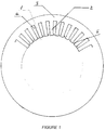
- position 1 is the enlargement or shoe of a pole; 2 is the radial pole; 3 is the yoke or cylinder head; 4 is the space between poles for housing the coil or winding; 5 is the slot between the pole shoes.
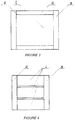
- Fig. 3 1 is the core or armature of the electromagnet; 2 is the coil wound in the core; 3 are the polar parts: yoke or cylinder head and shoe or collector.
- FIG No. 2 can be observed a section A-A, through the geometric axis, of the stator 1 armature assembly, formed by as many cores or axial poles 2 as required by the design chosen.
- the slot between the poles 3 may be as small as needed, because the conductors forming the stator winding 4 are introduced in each pole through the end 5 opposite to the area where the rotor 6 rotates, spaced apart from the stator by the air gap 7.
- the heads poles of the stator have enlargements 8, or shoes, between which, there is a slot 3, having a surface that is a very small fraction of the pole surface, for example, a tenth or less, or none.
- the heads of the stator winding are much shorter than in the conventional stator, because the turns 4, are housed in the axial enlargements of the poles 2, Fig. 2 , without interfering one another. That is why the length of the electric conductor of the improved winding is shorter than that of the conventional one. In a specific case of a commercial automotive alternator, the decrease or saving amounts to 35 %, which is quite significant.
- the yoke 9 may be a magnet.
- stator coils 4 are not superimposed, but are placed in successive segments of the axial cores 2, Fig 2 , so that may be manufactured with suitable molds and inserted in the cores, before being fastened to the yoke by appropriate mechanical means of common use.
- the air cooling of the stator coils is much better than in the conventional arrangement, due to the fact that the axial cores and the windings thereof leave large passages for the cooling air. All the above may be applied to an axial air gap.
- the improvements being claimed consist of replacing the conventional electromagnet with several electromagnets having a smaller section 1, Fig. 4 , in parallel, located between a soft iron plate joining the polarities, for example, North, which herein is known as collector or shoe 2, and another one joining the South polarities, which herein is known as cylinder head or yoke 3, having the same external dimensions as the conventional one, and whose content as far as the conductor wire is concerned for the same number of amperes per turn is much lower than that of the conventional electromagnet.
- the air cooling is better in the improved inductor, given the same external dimensions, since it has a larger length of wire exposed to the air, and a better air passage, than the conventional inductor.
- the cores of the magnets of the improved electromagnet may be permanent magnets, surrounded by their corresponding coils.
- the collector and the cylinder head may be permanent magnets, with coordinated polarities.
- excitation electromagnet may be applicable for other uses, since the described system, which in the patent is related to the excitation of electric machines, may be used in other machines and apparatuses as well.
Landscapes
- Engineering & Computer Science (AREA)
- Power Engineering (AREA)
- Iron Core Of Rotating Electric Machines (AREA)
- Permanent Magnet Type Synchronous Machine (AREA)
Applications Claiming Priority (2)
| Application Number | Priority Date | Filing Date | Title |
|---|---|---|---|
| ES201300586A ES2537220B1 (es) | 2013-06-21 | 2013-06-21 | Perfeccionamientos de las máquinas de campo magnético rotatorio |
| PCT/ES2014/070478 WO2014202808A1 (fr) | 2013-06-21 | 2014-06-10 | Améliorations apportées aux machines à champ magnétique rotatif |
Publications (2)
| Publication Number | Publication Date |
|---|---|
| EP3012949A1 true EP3012949A1 (fr) | 2016-04-27 |
| EP3012949A4 EP3012949A4 (fr) | 2017-02-15 |
Family
ID=52103992
Family Applications (1)
| Application Number | Title | Priority Date | Filing Date |
|---|---|---|---|
| EP14814074.2A Withdrawn EP3012949A4 (fr) | 2013-06-21 | 2014-06-10 | Améliorations apportées aux machines à champ magnétique rotatif |
Country Status (9)
| Country | Link |
|---|---|
| US (1) | US20160149446A1 (fr) |
| EP (1) | EP3012949A4 (fr) |
| JP (1) | JP6441327B2 (fr) |
| KR (1) | KR20160021857A (fr) |
| CN (1) | CN105453396A (fr) |
| BR (1) | BR212015031857U2 (fr) |
| ES (1) | ES2537220B1 (fr) |
| MX (1) | MX2015017736A (fr) |
| WO (1) | WO2014202808A1 (fr) |
Families Citing this family (1)
| Publication number | Priority date | Publication date | Assignee | Title |
|---|---|---|---|---|
| CN111509942A (zh) * | 2020-03-31 | 2020-08-07 | 河北大学 | 一种新型永磁发电机及其发电方法 |
Family Cites Families (32)
| Publication number | Priority date | Publication date | Assignee | Title |
|---|---|---|---|---|
| US1334832A (en) * | 1919-10-23 | 1920-03-23 | Gen Electric | Dynamo-electric machine |
| US2192073A (en) * | 1937-02-05 | 1940-02-27 | Philips Nv | Electric generator |
| CH208422A (de) * | 1938-08-15 | 1940-01-31 | Maier Haupt Otto | Stromerzeuger für Fahrradbeleuchtung, Taschenlampen und dergl. |
| US3619678A (en) * | 1970-01-22 | 1971-11-09 | Goodyear Tire & Rubber | Dual output ac transducer |
| US4221985A (en) * | 1978-04-14 | 1980-09-09 | Eaton Corporation | Vehicle tachometer generator |
| US4511831A (en) * | 1981-04-07 | 1985-04-16 | Mcinnis Stirling A | Speed control of a D.C. electric motor |
| JPH0158288U (fr) * | 1987-10-05 | 1989-04-12 | ||
| US5168187A (en) * | 1991-02-20 | 1992-12-01 | Dana Corporation, Warner Electric Brake & Clutch Division | Axial pole stepping motor |
| US5418436A (en) * | 1993-08-19 | 1995-05-23 | International Business Machines Corporation | Motor starting method and apparatus |
| US6053705A (en) * | 1996-09-10 | 2000-04-25 | Sulzer Electronics Ag | Rotary pump and process to operate it |
| EP0899857B1 (fr) * | 1997-08-25 | 2007-11-28 | LUST ANTRIEBSTECHNIK GmbH | Dispositif rotatif avec palier magnétique |
| KR20010102036A (ko) * | 1999-02-10 | 2001-11-15 | 추후제출 | 축 형태의 자속을 지닌 전기 다중극 모터/발전기 |
| EP1063753B1 (fr) * | 1999-06-22 | 2009-07-22 | Levitronix LLC | Entraînement électrique rotatif comprenant un rotor suspendu magnétiquement |
| TW553555U (en) * | 2001-09-26 | 2003-09-11 | Jia-Hau Fan | Modular stator structure |
| FR2835978B1 (fr) * | 2001-12-12 | 2005-08-05 | Valeo Equip Electr Moteur | Alternateur, notamment pour vehicule automobile |
| US6707221B2 (en) * | 2002-04-08 | 2004-03-16 | General Electric Company | Axial flux machine, stator and fabrication method |
| JP4298311B2 (ja) * | 2003-02-07 | 2009-07-15 | キヤノン株式会社 | モータ |
| DE102004055578A1 (de) * | 2003-12-06 | 2005-06-30 | Luk Lamellen Und Kupplungsbau Beteiligungs Kg | Bürstenlose elektrische Maschine |
| FR2876231B1 (fr) * | 2004-05-06 | 2006-12-22 | Gerard Koehler | Machine dynamo-electrique tournante a reluctance variable a globalisation des circuits magnetiques, electriques et de polarisation et son procede de fabrication |
| GB2428903B (en) * | 2005-08-03 | 2009-10-07 | Imra Europ S A S Uk Res Ct | Salient pole electrical machine |
| JP3811179B1 (ja) * | 2005-10-06 | 2006-08-16 | 山洋電気株式会社 | モータ用ステータ |
| TWI384123B (zh) * | 2006-02-23 | 2013-02-01 | Levitronix Technologies Llc | 旋轉泵,具有旋轉泵的液體動力混合機,及使用旋轉泵來處理流體 |
| JP5122124B2 (ja) * | 2006-07-26 | 2013-01-16 | 日立金属株式会社 | アキシャルギャップ型回転機、及びこれを搭載した空調用圧縮機、送風機、及び自動車 |
| CN100525009C (zh) * | 2007-09-21 | 2009-08-05 | 东南大学 | 双通道容错式磁通切换永磁电机及其控制方法 |
| KR100932687B1 (ko) * | 2007-10-24 | 2009-12-21 | 한국과학기술연구원 | 고 토크밀도 하이브리드 스테핑 모터 |
| EP2280471B1 (fr) * | 2009-07-30 | 2019-08-07 | Levitronix GmbH | Entraînement rotatif électrique |
| US8872395B2 (en) * | 2009-11-04 | 2014-10-28 | Fraen Mechatronics, Llc | Rotary single-phase electromagnetic actuator |
| JP5515662B2 (ja) * | 2009-11-16 | 2014-06-11 | シンフォニアテクノロジー株式会社 | アキシャルモータ |
| EP2709688B1 (fr) * | 2011-05-20 | 2018-01-03 | Levitronix GmbH | Machine rotative et dispositif doté d'une machine rotatif |
| EP3232549B1 (fr) * | 2016-04-14 | 2020-12-16 | Levitronix GmbH | Entrainement rotatif electromagnetique et dispositif de rotation |
| WO2019125718A1 (fr) * | 2017-12-22 | 2019-06-27 | Massachusetts Institute Of Technology | Moteurs de tranches homopolaires sans palier |
| US11177719B2 (en) * | 2018-05-18 | 2021-11-16 | Levitronix Gmbh | Electromagnetic rotary drive and rotational device |
-
2013
- 2013-06-21 ES ES201300586A patent/ES2537220B1/es active Active
-
2014
- 2014-06-10 WO PCT/ES2014/070478 patent/WO2014202808A1/fr not_active Ceased
- 2014-06-10 EP EP14814074.2A patent/EP3012949A4/fr not_active Withdrawn
- 2014-06-10 MX MX2015017736A patent/MX2015017736A/es unknown
- 2014-06-10 CN CN201480046281.2A patent/CN105453396A/zh active Pending
- 2014-06-10 KR KR1020167001463A patent/KR20160021857A/ko not_active Ceased
- 2014-06-10 JP JP2016520554A patent/JP6441327B2/ja active Active
- 2014-06-10 US US14/900,179 patent/US20160149446A1/en not_active Abandoned
- 2014-06-10 BR BR212015031857U patent/BR212015031857U2/pt not_active Application Discontinuation
Non-Patent Citations (1)
| Title |
|---|
| See references of WO2014202808A1 * |
Also Published As
| Publication number | Publication date |
|---|---|
| JP6441327B2 (ja) | 2018-12-19 |
| ES2537220B1 (es) | 2016-03-17 |
| EP3012949A4 (fr) | 2017-02-15 |
| US20160149446A1 (en) | 2016-05-26 |
| BR212015031857U2 (pt) | 2016-08-16 |
| MX2015017736A (es) | 2016-04-04 |
| WO2014202808A1 (fr) | 2014-12-24 |
| KR20160021857A (ko) | 2016-02-26 |
| ES2537220A1 (es) | 2015-06-03 |
| CN105453396A (zh) | 2016-03-30 |
| JP2016522672A (ja) | 2016-07-28 |
Similar Documents
| Publication | Publication Date | Title |
|---|---|---|
| CN111293848B (zh) | 无槽无刷直流马达/致动器 | |
| KR101255934B1 (ko) | 횡방향 스위치드 릴럭턴스 모터 | |
| RU2603680C2 (ru) | Электродвигатель с обмоткой, не содержащей железа | |
| US20170338726A1 (en) | Polyphase motor having an alternation of permanent magnets and salient poles | |
| WO2014205523A4 (fr) | Machine électrique dotée d'un stator interne | |
| CN106981966B (zh) | 一种永磁偏置无轴承开关磁阻起动/发电机 | |
| US20130134805A1 (en) | Switched reluctance motor | |
| JP2009540788A (ja) | リングコイルモータ | |
| KR20140037375A (ko) | 모터의 회전자와 이를 포함하는 동기 모터 및 권선형 회전자 동기 모터 | |
| US20130214623A1 (en) | Switched reluctance motor | |
| CN106655553B (zh) | 一种复合结构电机 | |
| CN108880184A (zh) | 一种新型短动子凸极结构的直线旋转永磁作动器 | |
| US20190312476A1 (en) | Motor | |
| CN102694444A (zh) | 定位力互补式双定子圆筒型直线电机 | |
| JP2014155373A (ja) | マルチギャップ型回転電機 | |
| CN109412370A (zh) | 磁通切换式直线旋转永磁作动器 | |
| US20150084472A1 (en) | Electrical Power Motor-Generator Excited by Magnetic Transference | |
| US10770956B2 (en) | Electric machine | |
| JP2016123143A (ja) | ロータ及びその製造方法、並びにそれを備えた回転電気機械 | |
| US20160149446A1 (en) | Improvements to rotating magnetic field machines | |
| CN107809159A (zh) | 一种新型单相圆筒型横向磁通开关磁阻直线电机 | |
| WO2011089797A1 (fr) | Rotor, machine électrique rotative utilisant celui-ci, et générateur d'électricité | |
| CN109818474A (zh) | 一种高磁阻扭矩集中绕组无刷电机 | |
| CN202713091U (zh) | 定位力互补式双定子圆筒型直线电机 | |
| RU2543512C1 (ru) | Линейный электродвигатель |
Legal Events
| Date | Code | Title | Description |
|---|---|---|---|
| PUAI | Public reference made under article 153(3) epc to a published international application that has entered the european phase |
Free format text: ORIGINAL CODE: 0009012 |
|
| 17P | Request for examination filed |
Effective date: 20160119 |
|
| AK | Designated contracting states |
Kind code of ref document: A1 Designated state(s): AL AT BE BG CH CY CZ DE DK EE ES FI FR GB GR HR HU IE IS IT LI LT LU LV MC MK MT NL NO PL PT RO RS SE SI SK SM TR |
|
| AX | Request for extension of the european patent |
Extension state: BA ME |
|
| DAX | Request for extension of the european patent (deleted) | ||
| A4 | Supplementary search report drawn up and despatched |
Effective date: 20170116 |
|
| RIC1 | Information provided on ipc code assigned before grant |
Ipc: H02K 21/44 20060101AFI20170110BHEP Ipc: H02K 19/06 20060101ALI20170110BHEP Ipc: H02K 21/12 20060101ALI20170110BHEP |
|
| 17Q | First examination report despatched |
Effective date: 20190424 |
|
| STAA | Information on the status of an ep patent application or granted ep patent |
Free format text: STATUS: THE APPLICATION IS DEEMED TO BE WITHDRAWN |
|
| 18D | Application deemed to be withdrawn |
Effective date: 20201117 |