EP3012964B1 - Verfahren und Vorrichtung zur Schätzung eines Drehmoments - Google Patents
Verfahren und Vorrichtung zur Schätzung eines Drehmoments Download PDFInfo
- Publication number
- EP3012964B1 EP3012964B1 EP14190048.0A EP14190048A EP3012964B1 EP 3012964 B1 EP3012964 B1 EP 3012964B1 EP 14190048 A EP14190048 A EP 14190048A EP 3012964 B1 EP3012964 B1 EP 3012964B1
- Authority
- EP
- European Patent Office
- Prior art keywords
- motor
- frequency
- axle
- rotor
- active power
- Prior art date
- Legal status (The legal status is an assumption and is not a legal conclusion. Google has not performed a legal analysis and makes no representation as to the accuracy of the status listed.)
- Active
Links
Images
Classifications
-
- G—PHYSICS
- G01—MEASURING; TESTING
- G01L—MEASURING FORCE, STRESS, TORQUE, WORK, MECHANICAL POWER, MECHANICAL EFFICIENCY, OR FLUID PRESSURE
- G01L5/00—Apparatus for, or methods of, measuring force, work, mechanical power, or torque, specially adapted for specific purposes
-
- H—ELECTRICITY
- H02—GENERATION; CONVERSION OR DISTRIBUTION OF ELECTRIC POWER
- H02P—CONTROL OR REGULATION OF ELECTRIC MOTORS, ELECTRIC GENERATORS OR DYNAMO-ELECTRIC CONVERTERS; CONTROLLING TRANSFORMERS, REACTORS OR CHOKE COILS
- H02P23/00—Arrangements or methods for the control of AC motors characterised by a control method other than vector control
- H02P23/14—Estimation or adaptation of motor parameters, e.g. rotor time constant, flux, speed, current or voltage
-
- G—PHYSICS
- G01—MEASURING; TESTING
- G01L—MEASURING FORCE, STRESS, TORQUE, WORK, MECHANICAL POWER, MECHANICAL EFFICIENCY, OR FLUID PRESSURE
- G01L3/00—Measuring torque, work, mechanical power, or mechanical efficiency, in general
- G01L3/02—Rotary-transmission dynamometers
-
- H—ELECTRICITY
- H02—GENERATION; CONVERSION OR DISTRIBUTION OF ELECTRIC POWER
- H02P—CONTROL OR REGULATION OF ELECTRIC MOTORS, ELECTRIC GENERATORS OR DYNAMO-ELECTRIC CONVERTERS; CONTROLLING TRANSFORMERS, REACTORS OR CHOKE COILS
- H02P21/00—Arrangements or methods for the control of electric machines by vector control, e.g. by control of field orientation
- H02P21/14—Estimation or adaptation of machine parameters, e.g. flux, current or voltage
- H02P21/20—Estimation of torque
Definitions
- This present disclosure relates to a method and apparatus for estimating torque, and, in particular, to a method and apparatus for estimating the torque of an axle of a running motor.
- the "Steinmetz equivalent circuit” may be used to describe how an induction motor's electrical input is transformed into useful mechanical energy output.
- the parameters of the Steinmetz equivalent circuit can be obtained by starting the motor in a "no load” condition and in a "locked rotor” condition.
- both conditions are disruptive to normal operation of the motor since they each require the motor to be in a non-running state.
- DSP digital signal processing
- US Patent No. US 6 505 132 B1 (Takaku ) describes a detection device for detecting instantaneously generated torque and an average generated torque of a three-phase motor. In advance of determining the instantaneously generated torque, the described device is required to detect a "no load" current of the motor.
- Data indicative of the total electrical active power, P, supplied to the motor may be obtained by measuring the total electrical active power, P, supplied to the motor.
- Measuring the total electrical active power, P, supplied to the motor may include measuring one or both of an instantaneous motor voltage and an instantaneous motor current on each connected phase of the motor.
- Receiving data indicative of the total electrical active power, P may include receiving data indicative of one or more frequency components, P 1 , P 2 , P 3 , P 4 ,..., of the total electrical active power, P, and receiving data indicative of symmetrical components, P + , P - , of the fundamental frequency component, P 1 .
- Data indicative of one or more frequency components, P 1 , P 2 , P 3 , P 4 ,..., of the total electrical active power, P may be obtained by Fourier analysis of total electrical active power, P, and/or data indicative of symmetrical components, P + , P - , of the fundamental frequency component, P 1 , may be obtained by symmetrical decomposition of the fundamental frequency component, P 1 .
- Receiving data indicative of a rotor speed, n r , or rotor frequency, f r , of the axle includes receiving data indicative of one or more of the fundamental electrical frequency, f 1 , of the current supplied to the motor, the load dependent slip, s, of the motor, the frequency shift, ⁇ f, due to rotor slip, and the number of poles, p, of the motor.
- the method may further include the step of determining the load dependent slip, s, by analysis of a frequency spectrum of the current supplied to the motor.
- the method may further comprise the step of creating a frequency spectrum of the current supplied to the motor.
- the motor may be an asynchronous induction motor.
- an apparatus configured to carry out any of the methods described above in relation to the first aspect of the present disclosure.
- Embodiments of the present disclosure provide a method and apparatus for estimating the torque of an axle of a running motor.
- the method and apparatus may be used to estimate torque without interrupting operation of the motor.
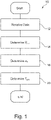
- Figure 1 illustrates a method 10 of determining the electromechanical torque, T em , of an axle of a running motor.
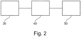
- the method 10 may be performed by an apparatus 40 as illustrated in Figure 2 .
- the apparatus 40 may be positioned between a power source 30 and a motor 50.
- the method 10 comprises a step 12 of receiving data that is indicative of the total electrical active power, P, supplied to the motor 50 by the power source 30. Additionally at step 12, data is received that is indicative of a rotor speed, n r , or rotor frequency, f r , of the axle.
- the electromechanical power, P em supplied to an axle of the motor 50 is determined using the data indicative of the total electrical active power, P.
- the angular rotor frequency, ⁇ r of the axle is determined using the data indicative of rotor speed, n r , or rotor frequency, f r , of the axle.
- the electromechanical axle torque, T em is determined at step 20.
- the electromechanical axle torque, T em is estimated using only data relating to the total electrical active power, P, supplied to the motor 50 by the power source and the rotor speed, n r , or rotor frequency, f r , of the axle.
- this data may be received without interrupting the operation of the motor 50.
- data indicative of the total electrical active power, P, supplied to the motor 50 is obtained by measuring the total electrical active power, P, supplied to the motor 50.
- the total electrical active power, P, supplied to the motor 50 may be determined by measurement of the instantaneous motor voltage and instantaneous motor current on each connected phase of the motor 50.
- the total electrical active power, P, supplied to the motor 50 may be derived using the measured voltages and currents.
- the voltage and/or current may be measured in accordance with IEC 61000-4-30 , and/or the total electrical active power, P, may be calculated in accordance with IEEE Std 1459.
- the mechanical power at the axle of a motor arises due to the electrical active power, P , supplied to the motor. However, not all electrical active power, P, is converted into mechanical power.
- the total electrical active power may therefore be decomposed into three categories, namely (i) electrical active power components positively contributing to mechanical power, (ii) electrical active power negatively contributing to mechanical power, and (iii) electrical active power components not contributing to mechanical power.
- the total electrical active power, P may be decomposed into its individual frequency components.
- this decomposition may be achieved by Fourier analysis.
- this decomposition may be achieved by a fast Fourier transform (FFT) in accordance with the standard IEC 61000-4-7.
- FFT fast Fourier transform
- the fundamental frequency is typically the mains frequency (e.g. 50 Hz or 60 Hz), however, in the case of electronic variable speed drive circuits, the fundamental frequency may be a varying frequency.
- the fundamental component P 1 may be further decomposed into its symmetrical components using the established method symmetrical decomposition (originally proposed by C. L. Fortescue).
- the power components not contributing to the mechanical power at the axle may, for example, generate heat, noise or mechanical malfunction, but contribute neither positively nor negatively to the mechanical power supplied to the axle.
- one method for determining the electromechanical power, P em is to measure or otherwise obtain data indicative of the total electrical active power, P, supplied to the axle (e.g., by measuring the instantaneous voltage and current as described above), and then decomposing the total active power, P, to obtain the components required to determine P em .
- Any method or apparatus in which data that is indicative of the total electrical active power, P, is received and then used to determine electromechanical power, P em may be used within the scope of the present disclosure.
- the rotor speed, n r , or rotor frequency, f r , of the axle may be ascertained by receiving data indicative of the slip, s, and the synchronous speed, n s , or frequency, f s .
- the rotor speed, n r , or rotor frequency, f r , of the axle may be ascertained by receiving data indicative of the slip, s, the fundamental electrical frequency, f 1 , and the number of poles of the motor, p.
- the nominal speed n nom and nominal frequency f nom are quantities defined on the motor nameplate (also known as the motor type shield or motor rating plate) found on most, if not all, motors (typically listed simply as "speed” and "frequency").
- ⁇ f (and f 1 , if unknown) can be obtained by analysis of the frequency spectrum of the motor current.
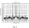
- Figure 3 shows an example of a motor current frequency spectrum where the fundamental frequency, f 1 , is 60 Hz. On either side of the fundamental frequency, f 1 , there is a notable sideband frequency that is shifted relative to the fundamental frequency, f 1 , by ⁇ f.
- analysis of the frequency spectrum can provide the value of ⁇ f.
- the resolution of the frequency spectrum should be sufficiently great.
- a resolution of 0.1 to 0.5 Hz is sufficient.
- the sideband signals may be significantly lower than the signal at the fundamental frequency, f 1
- the frequency spectrum is preferably obtained with a sufficiently great dynamic range to permit the sidebands to be accurately identified.
- the sidebands are approximately 60 dB lower than the fundamental component, f 1 .
- ⁇ r 2. ⁇ .f r
- ⁇ r 2 . ⁇ . 1 ⁇ s .2 . f 1 / p .
- the angular rotor frequency, ⁇ r may be determined.
- the electromechanical axle torque, T em P em / ⁇ r .
- Certain methods according to embodiments of the present disclosure are particularly suited to calculating electromechanical axle torque in asynchronous motors.
- the skilled person will appreciate that for synchronous motors, the effects of slip will not apply.
- the apparatus 40 may be any suitable apparatus for obtaining the required data and determining electromechanical axle torque, T em , in accordance with methods according to embodiments of the present disclosure.
- the apparatus 40 may include any suitable means, sensor, or system for measuring the instantaneous voltage and current on each connected phase of the motor 50.
- the apparatus 40 may include a control means in the form of a control unit that comprises one or more processors for executing computer software instructions that may be arranged, when executed, to perform a method according to an embodiment of the present disclosure.
- the software instructions may be stored in a non-transitory computer-readable medium, such as a memory of the control unit.
- the control unit may be communicably coupled to the means, sensor or system (if present) for measuring the instantaneous voltage and current on each connected phase of the motor 50.
- the apparatus 40 may include a display for displaying information, which may include, for example, the calculated electromechanical axle torque, T em .
- the apparatus may include one or more transmitters and/or receivers for transmitting and/or receiving data.
- the apparatus 40 may be configured to transmit data indicative of the electromechanical axle torque, T em .
Landscapes
- Engineering & Computer Science (AREA)
- Power Engineering (AREA)
- Physics & Mathematics (AREA)
- General Physics & Mathematics (AREA)
- Control Of Ac Motors In General (AREA)
- Tests Of Circuit Breakers, Generators, And Electric Motors (AREA)
Claims (15)
- Verfahren (10) zum Schätzen des Drehmoments einer Achse eines laufenden Motors (50), umfassend:Empfangen von Daten (12), die indikativ für die gesamte elektrische Wirkleistung P sind, die dem Motor zugeführt wird;Zerlegen der gesamten elektrischen Wirkleistung P in eine Grundfrequenzkomponente P1 und harmonische Frequenzkomponenten;Zerlegen der Grundfrequenzkomponente P1 in symmetrische Komponenten, die mindestens eine Mitsystem-Leistungskomponente P+ und eine Gegensystem-Leistungskomponente P- beinhalten;Bestimmen (14) der elektromechanischen Leistung, Pem, die der Achse zugeführt wird, unter Verwendung der Daten, die indikativ für die gesamte elektrische Wirkleistung, P, sind, durch Subtrahieren einer Summe der Gegensystem-Leistungskomponente, P-, und der Oberwellenfrequenzkomponenten, die einen negativen Beitrag zur mechanischen Leistung an der Achse bereitstellen, von einer Summe der Mitsystem-Leistungskomponente, P+, und der Oberwellenfrequenzkomponenten, die einen positiven Beitrag zu der mechanischen Leistung an der Achse bereitstellen;Empfangen von Daten, die indikativ für eine Rotordrehzahl, nr, oder eine Rotorfrequenz, fr, der Achse sind, einschließlich eines Empfangens von Daten, die indikativ für den lastabhängigen Schlupf, s, und die Synchrondrehzahl, ns, oder die Frequenz, fs, des Motors sind;Bestimmen (16) einer Rotorwinkelfrequenz, ωr, der Achse unter Verwendung der Daten, die indikativ für die Rotordrehzahl, nr, oder die Rotorfrequenz, fr, der Achse sind; undBestimmen (20) des elektromechanischen Achsmoments, Tem, unter Verwendung der bestimmten elektromechanischen Leistung, Pem, und der bestimmten Rotorwinkelfrequenz, ωr.
- Verfahren nach Anspruch 1, wobei Daten, die indikativ für die gesamte elektrische Gesamtwirkleistung, P, sind, die dem Motor zugeführt wird, durch Messen der gesamten elektrischen Gesamtwirkleistung, P, die dem Motor zugeführt wird, erlangt werden.
- Verfahren nach Anspruch 2, wobei ein Messen der gesamten elektrischen Gesamtwirkleistung, P, die dem Motor zugeführt wird, ein Messen einer oder beider von einer momentanen Motorspannung und eines momentanen Motorstroms an jeder verbundenen Phase des Motors beinhaltet.
- Verfahren nach einem der vorherigen Ansprüche, wobei ein Empfangen von Daten, die indikativ für die gesamte elektrische Gesamtwirkleistung, P, sind, einen Empfangen von Daten beinhaltet, die indikativ für eine oder mehrere Frequenzkomponenten, P1, P2, P3, P4, ..., der gesamten elektrischen Wirkleistung, P, sind.
- Verfahren nach Anspruch 4, wobei Daten, die indikativ für eine oder mehrere Frequenzkomponenten, P1, P2, P3, P4, ..., der gesamten elektrischen Wirkleistung, P, sind, durch Fourier-Analyse der gesamten elektrischen Wirkleistung, P, erlangt werden.
- Verfahren nach einem der vorherigen Ansprüche, wobei ein Bestimmen von Daten, die indikativ für eine Rotordrehzahl, nr, oder eine Rotorfrequenz, fr, der Achse sind, ein Empfangen von Daten beinhaltet, die indikativ für eines oder mehrere von der elektrischen Grundfrequenz, f1, dem Strom, der dem Motor zugeführt wird, dem lastabhängigen Schlupf, s, des Motors, der Frequenzverschiebung, Δf, aufgrund des Rotorschlupfs und der Anzahl von Polen, p, des Motors sind.
- Verfahren nach Anspruch 6, wobei die Rotordrehzahl, nr, oder die Rotorfrequenz, fr, der Achse bestimmt wird, wobei fr (Hz) = (1-s)·fs = (1-s)·2·f1/p = nr(U/min)/60 ist und fs die Synchronfrequenz des Motors ist.
- Verfahren nach Anspruch 6 oder 7, wobei das Verfahren ferner den Schritt eines Bestimmens der Polzahl p des Motors umfasst, wobei p = INTEGER((120·fnom)/nnom) ist, wobei nnom die Nenndrehzahl des Motors ist, der mit seiner Nennfrequenz, fnom, betrieben wird.
- Verfahren nach einem der Ansprüche 6 bis 8, wobei das Verfahren ferner den Schritt eines Bestimmens des lastabhängigen Schlupfs s durch Analyse eines Frequenzspektrums des Stroms beinhaltet, der dem Motor zugeführt wird.
- Verfahren nach Anspruch 9, wobei die Frequenzverschiebung Δf aufgrund des Rotorschlupfs und die elektrische Grundfrequenz f1 des Stroms, der dem Motor zugeführt wird, aus dem Frequenzspektrum des Stroms bestimmt werden, der dem Motor zugeführt wird, und der lastabhängige Schlupf s als s = 2·Δf/f1 bestimmt wird.
- Verfahren nach Anspruch 9 oder 10, wobei das Verfahren ferner den Schritt einer Erzeugung eines Frequenzspektrums des Stroms umfasst, der dem Motor zugeführt wird.
- Verfahren nach einem der Ansprüche 6 bis 11, wobei die Rotorwinkelfrequenz, ωr, der Achse durch Berechnen von ωr (rad/s) = 2 π fr = 4·ω·(1- s) ·f1/p bestimmt wird.
- Verfahren nach einem der vorherigen Ansprüche, wobei das elektromechanische Achsendrehmoment Tem durch Berechnen von Tem = Pem/ ωr bestimmt wird.
- Verfahren nach einem der vorherigen Ansprüche, wobei der Motor ein Asynchron-Induktionsmotor ist.
- Vorrichtung zum Schätzen des Drehmoments einer Achse eines laufenden Motors, wobei die Vorrichtung konfiguriert ist, um das Verfahren nach einem vorherigen Anspruch durchzuführen.
Priority Applications (3)
| Application Number | Priority Date | Filing Date | Title |
|---|---|---|---|
| EP14190048.0A EP3012964B1 (de) | 2014-10-23 | 2014-10-23 | Verfahren und Vorrichtung zur Schätzung eines Drehmoments |
| US14/919,547 US10712216B2 (en) | 2014-10-23 | 2015-10-21 | Method and apparatus for estimating torque |
| CN201510692241.1A CN105553376B (zh) | 2014-10-23 | 2015-10-23 | 用于估计转矩的方法和装置 |
Applications Claiming Priority (1)
| Application Number | Priority Date | Filing Date | Title |
|---|---|---|---|
| EP14190048.0A EP3012964B1 (de) | 2014-10-23 | 2014-10-23 | Verfahren und Vorrichtung zur Schätzung eines Drehmoments |
Publications (2)
| Publication Number | Publication Date |
|---|---|
| EP3012964A1 EP3012964A1 (de) | 2016-04-27 |
| EP3012964B1 true EP3012964B1 (de) | 2022-05-11 |
Family
ID=51795517
Family Applications (1)
| Application Number | Title | Priority Date | Filing Date |
|---|---|---|---|
| EP14190048.0A Active EP3012964B1 (de) | 2014-10-23 | 2014-10-23 | Verfahren und Vorrichtung zur Schätzung eines Drehmoments |
Country Status (3)
| Country | Link |
|---|---|
| US (1) | US10712216B2 (de) |
| EP (1) | EP3012964B1 (de) |
| CN (1) | CN105553376B (de) |
Families Citing this family (3)
| Publication number | Priority date | Publication date | Assignee | Title |
|---|---|---|---|---|
| US9941831B1 (en) | 2017-06-09 | 2018-04-10 | Caterpillar Inc. | Switched reluctance motor power estimation compensation for variable DC-link voltage |
| EP3907568A1 (de) * | 2020-05-08 | 2021-11-10 | Siemens Aktiengesellschaft | Verfahren und systeme zum bereitstellen eines simulationsmodells einer elektrischen rotatorischen maschine |
| CN114598192B (zh) * | 2021-02-04 | 2025-09-30 | 长城汽车股份有限公司 | 电机转矩的确定方法和装置 |
Family Cites Families (10)
| Publication number | Priority date | Publication date | Assignee | Title |
|---|---|---|---|---|
| US5057760A (en) * | 1985-01-31 | 1991-10-15 | Aeg Westinghouse Transportation Systems, Inc. | Torque determination for control of an induction motor apparatus |
| ES8706260A1 (es) | 1985-01-31 | 1987-06-01 | Westinghouse Electric Corp | Metodo para determinar el par de salida de un motor de corriente alterna |
| CN1067744A (zh) | 1991-06-08 | 1993-01-06 | 桂徐福泉 | 测量电功率和电能的方法及装置 |
| JP2001186794A (ja) | 1999-12-27 | 2001-07-06 | Kaneo Takaku | 三相交流電動機の高精度瞬時発生トルク検出装置 |
| JP2007222918A (ja) | 2006-02-24 | 2007-09-06 | Jfe Steel Kk | 幅圧下プレス設備におけるスリップ検出方法およびスリップ防止方法 |
| WO2008148075A1 (en) * | 2007-05-24 | 2008-12-04 | Alexander George Parlos | Machine condition assessment through power distribution networks |
| US8473228B2 (en) * | 2009-05-29 | 2013-06-25 | General Electric Company | Detection of rotor side anomaly in an induction machine |
| CN101788604A (zh) | 2010-01-19 | 2010-07-28 | 河北省电力研究院 | 一种基于频域分析和序分量分析的电功率及电量测量方法 |
| US9109517B2 (en) * | 2011-03-14 | 2015-08-18 | General Electric Company | Condition monitoring of mechanical drive train coupled with electrical machines |
| US8766578B2 (en) | 2012-02-27 | 2014-07-01 | Canadian Space Agency | Method and apparatus for high velocity ripple suppression of brushless DC motors having limited drive/amplifier bandwidth |
-
2014
- 2014-10-23 EP EP14190048.0A patent/EP3012964B1/de active Active
-
2015
- 2015-10-21 US US14/919,547 patent/US10712216B2/en active Active
- 2015-10-23 CN CN201510692241.1A patent/CN105553376B/zh active Active
Also Published As
| Publication number | Publication date |
|---|---|
| EP3012964A1 (de) | 2016-04-27 |
| CN105553376B (zh) | 2020-10-20 |
| US10712216B2 (en) | 2020-07-14 |
| US20160116354A1 (en) | 2016-04-28 |
| CN105553376A (zh) | 2016-05-04 |
Similar Documents
| Publication | Publication Date | Title |
|---|---|---|
| CN102947711B (zh) | 在ac感应电机中的转速探测系统和方法 | |
| Alwodai et al. | A comparison of different techniques for induction motor rotor fault diagnosis | |
| US10658961B2 (en) | Method for identifying the discrete instantaneous angular speed of an electromechanical system | |
| CN103502827B (zh) | 用于监测机电系统的状况方法和设备 | |
| US20160266208A1 (en) | Fault detection and diagnosis in an induction motor | |
| EP2942867B1 (de) | Induktionsmotordrehzahlschätzung | |
| US20220170987A1 (en) | Abnormality diagnosis device and abnormality diagnosis method | |
| JP2019221084A (ja) | 誘導電動機の過熱監視方法、誘導電動機監視装置、および誘導電動機の制御システム | |
| US10877098B2 (en) | Method for detecting a fault in an electrical machine | |
| JP2020153965A (ja) | 異常診断装置および異常診断方法 | |
| EP3012964B1 (de) | Verfahren und Vorrichtung zur Schätzung eines Drehmoments | |
| EP1729405B1 (de) | Gerät zur Drehzahlregelung eines feldorientiert geregelten Wechselstrommotors | |
| WO2019159249A1 (ja) | 電動機監視装置、電動機制御システム、鉄鋼圧延システムおよび電動機監視方法 | |
| TWI612765B (zh) | 決定三相感應馬達之固有特徵量的方法 | |
| CN107210691B (zh) | 位置检测器的角度误差校正装置以及角度误差校正方法 | |
| JP5332667B2 (ja) | 誘導電動機の制御装置 | |
| Mahmud | An adaptive EMD technique for induction motor fault detection | |
| Choi et al. | Broken Rotor Bar Detection in AC Induction Motors using Cascaded Flux-Current State Observer | |
| US20250244206A1 (en) | Electrical machine monitoring | |
| Montero et al. | Estimation of Torque Sharing for Industrial Dual Induction Motor Drives under Special Current Sensor Configuration | |
| Odavic et al. | Real-time fault diagnostics for a permanent magnet synchronous motor drive for aerospace applications | |
| JP2021029077A (ja) | 電圧形インバータの制御装置 | |
| Schreiber et al. | The application of various current-sensing devices for induction motor fault diagnostics |
Legal Events
| Date | Code | Title | Description |
|---|---|---|---|
| PUAI | Public reference made under article 153(3) epc to a published international application that has entered the european phase |
Free format text: ORIGINAL CODE: 0009012 |
|
| AK | Designated contracting states |
Kind code of ref document: A1 Designated state(s): AL AT BE BG CH CY CZ DE DK EE ES FI FR GB GR HR HU IE IS IT LI LT LU LV MC MK MT NL NO PL PT RO RS SE SI SK SM TR |
|
| AX | Request for extension of the european patent |
Extension state: BA ME |
|
| STAA | Information on the status of an ep patent application or granted ep patent |
Free format text: STATUS: REQUEST FOR EXAMINATION WAS MADE |
|
| 17P | Request for examination filed |
Effective date: 20161027 |
|
| RBV | Designated contracting states (corrected) |
Designated state(s): AL AT BE BG CH CY CZ DE DK EE ES FI FR GB GR HR HU IE IS IT LI LT LU LV MC MK MT NL NO PL PT RO RS SE SI SK SM TR |
|
| STAA | Information on the status of an ep patent application or granted ep patent |
Free format text: STATUS: EXAMINATION IS IN PROGRESS |
|
| 17Q | First examination report despatched |
Effective date: 20201021 |
|
| GRAP | Despatch of communication of intention to grant a patent |
Free format text: ORIGINAL CODE: EPIDOSNIGR1 |
|
| STAA | Information on the status of an ep patent application or granted ep patent |
Free format text: STATUS: GRANT OF PATENT IS INTENDED |
|
| INTG | Intention to grant announced |
Effective date: 20220218 |
|
| GRAS | Grant fee paid |
Free format text: ORIGINAL CODE: EPIDOSNIGR3 |
|
| GRAA | (expected) grant |
Free format text: ORIGINAL CODE: 0009210 |
|
| STAA | Information on the status of an ep patent application or granted ep patent |
Free format text: STATUS: THE PATENT HAS BEEN GRANTED |
|
| AK | Designated contracting states |
Kind code of ref document: B1 Designated state(s): AL AT BE BG CH CY CZ DE DK EE ES FI FR GB GR HR HU IE IS IT LI LT LU LV MC MK MT NL NO PL PT RO RS SE SI SK SM TR |
|
| REG | Reference to a national code |
Ref country code: GB Ref legal event code: FG4D |
|
| REG | Reference to a national code |
Ref country code: CH Ref legal event code: EP |
|
| REG | Reference to a national code |
Ref country code: AT Ref legal event code: REF Ref document number: 1492343 Country of ref document: AT Kind code of ref document: T Effective date: 20220515 |
|
| REG | Reference to a national code |
Ref country code: DE Ref legal event code: R096 Ref document number: 602014083673 Country of ref document: DE |
|
| REG | Reference to a national code |
Ref country code: IE Ref legal event code: FG4D |
|
| REG | Reference to a national code |
Ref country code: LT Ref legal event code: MG9D |
|
| REG | Reference to a national code |
Ref country code: NL Ref legal event code: MP Effective date: 20220511 |
|
| REG | Reference to a national code |
Ref country code: AT Ref legal event code: MK05 Ref document number: 1492343 Country of ref document: AT Kind code of ref document: T Effective date: 20220511 |
|
| PG25 | Lapsed in a contracting state [announced via postgrant information from national office to epo] |
Ref country code: SE Free format text: LAPSE BECAUSE OF FAILURE TO SUBMIT A TRANSLATION OF THE DESCRIPTION OR TO PAY THE FEE WITHIN THE PRESCRIBED TIME-LIMIT Effective date: 20220511 Ref country code: PT Free format text: LAPSE BECAUSE OF FAILURE TO SUBMIT A TRANSLATION OF THE DESCRIPTION OR TO PAY THE FEE WITHIN THE PRESCRIBED TIME-LIMIT Effective date: 20220912 Ref country code: NO Free format text: LAPSE BECAUSE OF FAILURE TO SUBMIT A TRANSLATION OF THE DESCRIPTION OR TO PAY THE FEE WITHIN THE PRESCRIBED TIME-LIMIT Effective date: 20220811 Ref country code: NL Free format text: LAPSE BECAUSE OF FAILURE TO SUBMIT A TRANSLATION OF THE DESCRIPTION OR TO PAY THE FEE WITHIN THE PRESCRIBED TIME-LIMIT Effective date: 20220511 Ref country code: LT Free format text: LAPSE BECAUSE OF FAILURE TO SUBMIT A TRANSLATION OF THE DESCRIPTION OR TO PAY THE FEE WITHIN THE PRESCRIBED TIME-LIMIT Effective date: 20220511 Ref country code: HR Free format text: LAPSE BECAUSE OF FAILURE TO SUBMIT A TRANSLATION OF THE DESCRIPTION OR TO PAY THE FEE WITHIN THE PRESCRIBED TIME-LIMIT Effective date: 20220511 Ref country code: GR Free format text: LAPSE BECAUSE OF FAILURE TO SUBMIT A TRANSLATION OF THE DESCRIPTION OR TO PAY THE FEE WITHIN THE PRESCRIBED TIME-LIMIT Effective date: 20220812 Ref country code: FI Free format text: LAPSE BECAUSE OF FAILURE TO SUBMIT A TRANSLATION OF THE DESCRIPTION OR TO PAY THE FEE WITHIN THE PRESCRIBED TIME-LIMIT Effective date: 20220511 Ref country code: ES Free format text: LAPSE BECAUSE OF FAILURE TO SUBMIT A TRANSLATION OF THE DESCRIPTION OR TO PAY THE FEE WITHIN THE PRESCRIBED TIME-LIMIT Effective date: 20220511 Ref country code: BG Free format text: LAPSE BECAUSE OF FAILURE TO SUBMIT A TRANSLATION OF THE DESCRIPTION OR TO PAY THE FEE WITHIN THE PRESCRIBED TIME-LIMIT Effective date: 20220811 Ref country code: AT Free format text: LAPSE BECAUSE OF FAILURE TO SUBMIT A TRANSLATION OF THE DESCRIPTION OR TO PAY THE FEE WITHIN THE PRESCRIBED TIME-LIMIT Effective date: 20220511 |
|
| PG25 | Lapsed in a contracting state [announced via postgrant information from national office to epo] |
Ref country code: RS Free format text: LAPSE BECAUSE OF FAILURE TO SUBMIT A TRANSLATION OF THE DESCRIPTION OR TO PAY THE FEE WITHIN THE PRESCRIBED TIME-LIMIT Effective date: 20220511 Ref country code: PL Free format text: LAPSE BECAUSE OF FAILURE TO SUBMIT A TRANSLATION OF THE DESCRIPTION OR TO PAY THE FEE WITHIN THE PRESCRIBED TIME-LIMIT Effective date: 20220511 Ref country code: LV Free format text: LAPSE BECAUSE OF FAILURE TO SUBMIT A TRANSLATION OF THE DESCRIPTION OR TO PAY THE FEE WITHIN THE PRESCRIBED TIME-LIMIT Effective date: 20220511 Ref country code: IS Free format text: LAPSE BECAUSE OF FAILURE TO SUBMIT A TRANSLATION OF THE DESCRIPTION OR TO PAY THE FEE WITHIN THE PRESCRIBED TIME-LIMIT Effective date: 20220911 |
|
| PG25 | Lapsed in a contracting state [announced via postgrant information from national office to epo] |
Ref country code: SM Free format text: LAPSE BECAUSE OF FAILURE TO SUBMIT A TRANSLATION OF THE DESCRIPTION OR TO PAY THE FEE WITHIN THE PRESCRIBED TIME-LIMIT Effective date: 20220511 Ref country code: SK Free format text: LAPSE BECAUSE OF FAILURE TO SUBMIT A TRANSLATION OF THE DESCRIPTION OR TO PAY THE FEE WITHIN THE PRESCRIBED TIME-LIMIT Effective date: 20220511 Ref country code: RO Free format text: LAPSE BECAUSE OF FAILURE TO SUBMIT A TRANSLATION OF THE DESCRIPTION OR TO PAY THE FEE WITHIN THE PRESCRIBED TIME-LIMIT Effective date: 20220511 Ref country code: EE Free format text: LAPSE BECAUSE OF FAILURE TO SUBMIT A TRANSLATION OF THE DESCRIPTION OR TO PAY THE FEE WITHIN THE PRESCRIBED TIME-LIMIT Effective date: 20220511 Ref country code: DK Free format text: LAPSE BECAUSE OF FAILURE TO SUBMIT A TRANSLATION OF THE DESCRIPTION OR TO PAY THE FEE WITHIN THE PRESCRIBED TIME-LIMIT Effective date: 20220511 Ref country code: CZ Free format text: LAPSE BECAUSE OF FAILURE TO SUBMIT A TRANSLATION OF THE DESCRIPTION OR TO PAY THE FEE WITHIN THE PRESCRIBED TIME-LIMIT Effective date: 20220511 |
|
| REG | Reference to a national code |
Ref country code: DE Ref legal event code: R097 Ref document number: 602014083673 Country of ref document: DE |
|
| PLBE | No opposition filed within time limit |
Free format text: ORIGINAL CODE: 0009261 |
|
| STAA | Information on the status of an ep patent application or granted ep patent |
Free format text: STATUS: NO OPPOSITION FILED WITHIN TIME LIMIT |
|
| PG25 | Lapsed in a contracting state [announced via postgrant information from national office to epo] |
Ref country code: AL Free format text: LAPSE BECAUSE OF FAILURE TO SUBMIT A TRANSLATION OF THE DESCRIPTION OR TO PAY THE FEE WITHIN THE PRESCRIBED TIME-LIMIT Effective date: 20220511 |
|
| 26N | No opposition filed |
Effective date: 20230214 |
|
| PG25 | Lapsed in a contracting state [announced via postgrant information from national office to epo] |
Ref country code: SI Free format text: LAPSE BECAUSE OF FAILURE TO SUBMIT A TRANSLATION OF THE DESCRIPTION OR TO PAY THE FEE WITHIN THE PRESCRIBED TIME-LIMIT Effective date: 20220511 Ref country code: MC Free format text: LAPSE BECAUSE OF FAILURE TO SUBMIT A TRANSLATION OF THE DESCRIPTION OR TO PAY THE FEE WITHIN THE PRESCRIBED TIME-LIMIT Effective date: 20220511 |
|
| REG | Reference to a national code |
Ref country code: CH Ref legal event code: PL |
|
| REG | Reference to a national code |
Ref country code: BE Ref legal event code: MM Effective date: 20221031 |
|
| PG25 | Lapsed in a contracting state [announced via postgrant information from national office to epo] |
Ref country code: LU Free format text: LAPSE BECAUSE OF NON-PAYMENT OF DUE FEES Effective date: 20221023 |
|
| PG25 | Lapsed in a contracting state [announced via postgrant information from national office to epo] |
Ref country code: LI Free format text: LAPSE BECAUSE OF NON-PAYMENT OF DUE FEES Effective date: 20221031 Ref country code: CH Free format text: LAPSE BECAUSE OF NON-PAYMENT OF DUE FEES Effective date: 20221031 |
|
| PG25 | Lapsed in a contracting state [announced via postgrant information from national office to epo] |
Ref country code: BE Free format text: LAPSE BECAUSE OF NON-PAYMENT OF DUE FEES Effective date: 20221031 |
|
| PG25 | Lapsed in a contracting state [announced via postgrant information from national office to epo] |
Ref country code: IE Free format text: LAPSE BECAUSE OF NON-PAYMENT OF DUE FEES Effective date: 20221023 |
|
| PG25 | Lapsed in a contracting state [announced via postgrant information from national office to epo] |
Ref country code: IT Free format text: LAPSE BECAUSE OF FAILURE TO SUBMIT A TRANSLATION OF THE DESCRIPTION OR TO PAY THE FEE WITHIN THE PRESCRIBED TIME-LIMIT Effective date: 20220511 |
|
| PG25 | Lapsed in a contracting state [announced via postgrant information from national office to epo] |
Ref country code: HU Free format text: LAPSE BECAUSE OF FAILURE TO SUBMIT A TRANSLATION OF THE DESCRIPTION OR TO PAY THE FEE WITHIN THE PRESCRIBED TIME-LIMIT; INVALID AB INITIO Effective date: 20141023 |
|
| PG25 | Lapsed in a contracting state [announced via postgrant information from national office to epo] |
Ref country code: CY Free format text: LAPSE BECAUSE OF FAILURE TO SUBMIT A TRANSLATION OF THE DESCRIPTION OR TO PAY THE FEE WITHIN THE PRESCRIBED TIME-LIMIT Effective date: 20220511 |
|
| PG25 | Lapsed in a contracting state [announced via postgrant information from national office to epo] |
Ref country code: MK Free format text: LAPSE BECAUSE OF FAILURE TO SUBMIT A TRANSLATION OF THE DESCRIPTION OR TO PAY THE FEE WITHIN THE PRESCRIBED TIME-LIMIT Effective date: 20220511 |
|
| PG25 | Lapsed in a contracting state [announced via postgrant information from national office to epo] |
Ref country code: TR Free format text: LAPSE BECAUSE OF FAILURE TO SUBMIT A TRANSLATION OF THE DESCRIPTION OR TO PAY THE FEE WITHIN THE PRESCRIBED TIME-LIMIT Effective date: 20220511 |
|
| PG25 | Lapsed in a contracting state [announced via postgrant information from national office to epo] |
Ref country code: MT Free format text: LAPSE BECAUSE OF FAILURE TO SUBMIT A TRANSLATION OF THE DESCRIPTION OR TO PAY THE FEE WITHIN THE PRESCRIBED TIME-LIMIT Effective date: 20220511 |
|
| PG25 | Lapsed in a contracting state [announced via postgrant information from national office to epo] |
Ref country code: BG Free format text: LAPSE BECAUSE OF FAILURE TO SUBMIT A TRANSLATION OF THE DESCRIPTION OR TO PAY THE FEE WITHIN THE PRESCRIBED TIME-LIMIT Effective date: 20220511 |
|
| PG25 | Lapsed in a contracting state [announced via postgrant information from national office to epo] |
Ref country code: BG Free format text: LAPSE BECAUSE OF FAILURE TO SUBMIT A TRANSLATION OF THE DESCRIPTION OR TO PAY THE FEE WITHIN THE PRESCRIBED TIME-LIMIT Effective date: 20220511 |
|
| PGFP | Annual fee paid to national office [announced via postgrant information from national office to epo] |
Ref country code: DE Payment date: 20251029 Year of fee payment: 12 |
|
| PGFP | Annual fee paid to national office [announced via postgrant information from national office to epo] |
Ref country code: GB Payment date: 20251027 Year of fee payment: 12 |
|
| PGFP | Annual fee paid to national office [announced via postgrant information from national office to epo] |
Ref country code: FR Payment date: 20251027 Year of fee payment: 12 |