EP3013079A1 - Drahtloskommunikationsvorrichtung und kommunikationssteuerungsverfahren - Google Patents
Drahtloskommunikationsvorrichtung und kommunikationssteuerungsverfahren Download PDFInfo
- Publication number
- EP3013079A1 EP3013079A1 EP14814278.9A EP14814278A EP3013079A1 EP 3013079 A1 EP3013079 A1 EP 3013079A1 EP 14814278 A EP14814278 A EP 14814278A EP 3013079 A1 EP3013079 A1 EP 3013079A1
- Authority
- EP
- European Patent Office
- Prior art keywords
- wireless
- communication device
- signal
- wireless communication
- interface
- Prior art date
- Legal status (The legal status is an assumption and is not a legal conclusion. Google has not performed a legal analysis and makes no representation as to the accuracy of the status listed.)
- Granted
Links
Images






Classifications
-
- H—ELECTRICITY
- H04—ELECTRIC COMMUNICATION TECHNIQUE
- H04W—WIRELESS COMMUNICATION NETWORKS
- H04W76/00—Connection management
- H04W76/10—Connection setup
-
- G—PHYSICS
- G08—SIGNALLING
- G08C—TRANSMISSION SYSTEMS FOR MEASURED VALUES, CONTROL OR SIMILAR SIGNALS
- G08C17/00—Arrangements for transmitting signals characterised by the use of a wireless electrical link
-
- H—ELECTRICITY
- H04—ELECTRIC COMMUNICATION TECHNIQUE
- H04L—TRANSMISSION OF DIGITAL INFORMATION, e.g. TELEGRAPHIC COMMUNICATION
- H04L12/00—Data switching networks
- H04L12/28—Data switching networks characterised by path configuration, e.g. LAN [Local Area Networks] or WAN [Wide Area Networks]
- H04L12/2803—Home automation networks
-
- H—ELECTRICITY
- H04—ELECTRIC COMMUNICATION TECHNIQUE
- H04L—TRANSMISSION OF DIGITAL INFORMATION, e.g. TELEGRAPHIC COMMUNICATION
- H04L12/00—Data switching networks
- H04L12/28—Data switching networks characterised by path configuration, e.g. LAN [Local Area Networks] or WAN [Wide Area Networks]
- H04L12/2803—Home automation networks
- H04L12/2807—Exchanging configuration information on appliance services in a home automation network
- H04L12/2809—Exchanging configuration information on appliance services in a home automation network indicating that an appliance service is present in a home automation network
-
- H—ELECTRICITY
- H04—ELECTRIC COMMUNICATION TECHNIQUE
- H04L—TRANSMISSION OF DIGITAL INFORMATION, e.g. TELEGRAPHIC COMMUNICATION
- H04L12/00—Data switching networks
- H04L12/28—Data switching networks characterised by path configuration, e.g. LAN [Local Area Networks] or WAN [Wide Area Networks]
- H04L12/2803—Home automation networks
- H04L12/2816—Controlling appliance services of a home automation network by calling their functionalities
- H04L12/282—Controlling appliance services of a home automation network by calling their functionalities based on user interaction within the home
-
- H—ELECTRICITY
- H04—ELECTRIC COMMUNICATION TECHNIQUE
- H04M—TELEPHONIC COMMUNICATION
- H04M1/00—Substation equipment, e.g. for use by subscribers
- H04M1/72—Mobile telephones; Cordless telephones, i.e. devices for establishing wireless links to base stations without route selection
- H04M1/724—User interfaces specially adapted for cordless or mobile telephones
- H04M1/72403—User interfaces specially adapted for cordless or mobile telephones with means for local support of applications that increase the functionality
- H04M1/72409—User interfaces specially adapted for cordless or mobile telephones with means for local support of applications that increase the functionality by interfacing with external accessories
- H04M1/72412—User interfaces specially adapted for cordless or mobile telephones with means for local support of applications that increase the functionality by interfacing with external accessories using two-way short-range wireless interfaces
-
- H—ELECTRICITY
- H04—ELECTRIC COMMUNICATION TECHNIQUE
- H04Q—SELECTING
- H04Q9/00—Arrangements in telecontrol or telemetry systems for selectively calling a substation from a main station, in which substation desired apparatus is selected for applying a control signal thereto or for obtaining measured values therefrom
-
- H—ELECTRICITY
- H04—ELECTRIC COMMUNICATION TECHNIQUE
- H04W—WIRELESS COMMUNICATION NETWORKS
- H04W4/00—Services specially adapted for wireless communication networks; Facilities therefor
-
- H—ELECTRICITY
- H04—ELECTRIC COMMUNICATION TECHNIQUE
- H04W—WIRELESS COMMUNICATION NETWORKS
- H04W72/00—Local resource management
- H04W72/50—Allocation or scheduling criteria for wireless resources
- H04W72/51—Allocation or scheduling criteria for wireless resources based on terminal or device properties
-
- H—ELECTRICITY
- H04—ELECTRIC COMMUNICATION TECHNIQUE
- H04M—TELEPHONIC COMMUNICATION
- H04M2250/00—Details of telephonic subscriber devices
- H04M2250/12—Details of telephonic subscriber devices including a sensor for measuring a physical value, e.g. temperature or motion
-
- H—ELECTRICITY
- H04—ELECTRIC COMMUNICATION TECHNIQUE
- H04N—PICTORIAL COMMUNICATION, e.g. TELEVISION
- H04N21/00—Selective content distribution, e.g. interactive television or video on demand [VOD]
- H04N21/40—Client devices specifically adapted for the reception of or interaction with content, e.g. set-top-box [STB]; Operations thereof
- H04N21/41—Structure of client; Structure of client peripherals
- H04N21/4104—Peripherals receiving signals from specially adapted client devices
- H04N21/4122—Peripherals receiving signals from specially adapted client devices additional display device, e.g. video projector
-
- H—ELECTRICITY
- H04—ELECTRIC COMMUNICATION TECHNIQUE
- H04N—PICTORIAL COMMUNICATION, e.g. TELEVISION
- H04N21/00—Selective content distribution, e.g. interactive television or video on demand [VOD]
- H04N21/40—Client devices specifically adapted for the reception of or interaction with content, e.g. set-top-box [STB]; Operations thereof
- H04N21/43—Processing of content or additional data, e.g. demultiplexing additional data from a digital video stream; Elementary client operations, e.g. monitoring of home network or synchronising decoder's clock; Client middleware
- H04N21/436—Interfacing a local distribution network, e.g. communicating with another STB or one or more peripheral devices inside the home
- H04N21/43615—Interfacing a Home Network, e.g. for connecting the client to a plurality of peripherals
-
- H—ELECTRICITY
- H04—ELECTRIC COMMUNICATION TECHNIQUE
- H04W—WIRELESS COMMUNICATION NETWORKS
- H04W88/00—Devices specially adapted for wireless communication networks, e.g. terminals, base stations or access point devices
- H04W88/02—Terminal devices
- H04W88/06—Terminal devices adapted for operation in multiple networks or having at least two operational modes, e.g. multi-mode terminals
Definitions
- the present invention relates to a wireless communication device and a communication control device.
- Patent Literature 1 discloses a technique that allows the user to specify a connection target using a so-called "touch" in close proximity wireless communication technology such as near-field communication (NFC).
- Patent Literature 2 discloses a technique that determines a "touch” based on the received signal strength of wireless signals.
- a communication control device including: a processor configured to execute a program allowing a second wireless interface to establish a connection with a first device, when a first wireless signal having directivity is sent via a first wireless interface and a second wireless signal received via the second wireless interface includes an indicator indicating that the first wireless signal is received by the first device being a sending source device of the second wireless signal; and a memory configured to store the program.
- a wireless communication device including: a first wireless interface capable of receiving a first wireless signal having directivity; a second wireless interface; and a controller configured to allow a second wireless signal to be sent from the second wireless interface to a first device when the first wireless signal is received by the first wireless interface, the second wireless signal including an indicator indicating that the first wireless signal is received, the first device being configured to search for a connection target in a wireless communication mode supported by the second wireless interface.
- FIG. 1 is a diagram illustrated to describe an overview of a communication control system 1 according to one embodiment.
- the communication control system 1 includes a wireless communication device 100 and wireless communication devices 150a, 150b, 150c, and 150d.
- the wireless communication device 100 is a terminal device operated by a user Ua.
- the wireless communication device 100 has a wireless interface capable of performing wireless communication with other devices in peer-to-peer mode.
- the wireless interface may be a wireless LAN interface.
- the wireless communication device 100 is a smartphone.
- the wireless communication device 100 is not limited to such example.
- An example of the wireless communication device 100 may include tablet personal computers (PCs), portable game consoles, personal digital assistants (PDAs), and any type of terminal devices such as portable content players.
- the wireless communication devices 150a, 150b, 150c, and 150d are electronic equipment connectable to the wireless communication device 100.
- the wireless communication device 150a is a television set.
- the wireless communication device 150b is a video recording/playback device.
- the wireless communication device 150c is a printer.
- the wireless communication device 150d is a notebook PC.
- the wireless communication devices 150a, 150b, 150c, and 150d have a wireless interface (e.g., wireless LAN interface) that supports a wireless communication mode common to the wireless communication device 100.
- the user Ua can specify the wireless communication device 150 as a target to be connected to the wireless communication device 100 by allowing the wireless communication device 100 to be touched with the wireless communication device 150a.
- the user Ua who is located at a distance from the wireless communication device 150a probably does not want to move just because of performing the touch operation.
- connection target for example, when the content included in the wireless communication device 100 is caused to be reproduced by the wireless communication device 150b through a wireless connection, when data included in the wireless communication device 100 is caused to be printed by the wireless communication device 150c through a wireless connection, and when data is caused to be exchanged between the wireless communication device 100 and the wireless communication device 150d through a wireless connection. Therefore, it is desirable to provide a mechanism for allowing the user to select easily a target to be connected wirelessly without causing the user to perform an operation that imposes a burden on the user.
- a wireless interface that sends a wireless signal having directivity to the wireless communication device 100.
- An example of the wireless interface for directional signals may include an infrared interface such as an infrared data association (IrDA) interface.
- the wireless interface for directional signals may be a visible light interface (a laser pointer may be included therein) or a millimeter-wave air interface.
- the corresponding wireless interface for receiving directional signals is provided in the wireless communication device 150. The user Ua directs an infrared interface of the wireless communication device 100 toward a desired connection target to allow the wireless communication device 100 to send directional signals.
- a device that requests the establishment of a wireless connection such as the wireless communication device 100 shown in FIG. 1 , will be herein referred to as a request side device.
- a device that receives a request to establish a wireless connection such as the wireless communication devices 150a, 150b, 150c, and 150d (the wireless communication device 150) shown in FIG. 1 , will be herein referred to as a response side device or a connection target.
- a detailed exemplary configuration of the request side device will be described.
- a detailed exemplary configuration of the response side device will be described.
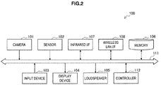
- FIG. 2 is a block diagram illustrating an exemplary configuration of the wireless communication device 100.
- the wireless communication device 100 is configured to include a camera 101, a sensor 102, an input device 103, a display device 104, a loudspeaker 105, a memory 106, an infrared interface 107, a wireless LAN interface 108, a bus 111, and a controller 112.
- the camera includes an image sensor such as charge-coupled device (CCD) or complementary-metal-oxide semiconductor (CMOS) and generates a captured image.
- the sensor 102 may be at least one among a sensor group including a positioning sensor, a gyro sensor, a geomagnetic sensor, and an acceleration sensor.
- An example of the input device 103 includes a touch sensor, a keypad, a keyboard, a button, and a switch.
- the input device 103 receives the user's operation or information input.
- the touch sensor detects a contact on a screen of the display device 104.
- the display device 104 includes a screen of a liquid display device (LCD), an organic light-emitting diode (OLED) display, or the like.
- the loudspeaker 105 converts audio signals outputted from the wireless communication device 100 to sound.
- the memory 106 includes random-access memory (RAM) and read-only memory (ROM). Data and a program executed by the controller 112 described
- the infrared interface 107 is a first wireless interface configured to send a directional signal that is a wireless signal (infrared signal) having directivity.
- the infrared interface 107 sends a directional signal in response to the user's instruction under the control of the controller 112 described later.
- the infrared interface 107 sends a directional signal having a predetermined format.
- the infrared interface 107 is provided with a light-emitting portion arranged thereon to allow the user to easily discriminate the optical axis direction of the directional signal being sent (e.g., to allow the optical axis direction to be perpendicular to a surface of a housing).
- the user instructs the infrared interface 107 to send a directional signal while directing the light-emitting portion toward the direction where a connection target for wireless LAN connection is present.
- the directional signal sent from the infrared interface 107 reaches a connection target at which the user is pointing.
- the directional signal does not reach a device outside the range of the signal directivity.
- the directional signal described above that is sent at the time of connection attempt of a wireless LAN connection contains information used to identify the wireless communication device 100.
- the identification information is used for the response side device receiving the directional signal to determine that the request side device requesting a wireless LAN connection is the wireless communication device 100.
- the identification information may be a media access control (MAC) address or may be any other identifiers.
- the directional signal may contain protocol information that indicates a protocol of the service being requested.
- the protocol information may be a flag, or may be a protocol name or code.
- the format of a directional signal to describe management information that can include these identification information and protocol information may be defined in advance.
- the wireless LAN interface 108 is a second wireless interface that operates in accordance with a wireless LAN mode.
- the wireless LAN interface 108 may establish a peer-to-peer wireless connection with the response side device according to the connection procedure using Wi-Fi Direct or in ad-hoc mode.
- the wireless connection established by the wireless LAN interface 108 may be used to transmit any type of data including display video data, content data, print data, and application data.
- the wireless LAN interface 108 when establishing a wireless connection with the response side device, sends a service inquiry signal.
- the service inquiry signal is a signal used to obtain a reply of service information about the service supported by the response side device.
- the wireless LAN interface 108 may send a search signal used to search for a connection target to which a service inquiry signal is to be sent prior to the service inquiry. Alternatively, it may send a single signal serving as both the service inquiry signal and search signal.
- the service inquiry signal may be a service discovery request (query) in the service discovery procedure using Wi-Fi Direct.
- the search signal may be a probe request in the device discovery procedure using Wi-Fi Direct.
- the bus 111 connects the camera 110, the sensor 102, the input device 103, the display device 104, the loudspeaker 105, the memory, the infrared interface 107, the wireless LAN interface 108, and the controller 112 with each other.
- the controller 112 instructs the wireless LAN interface 108 to search for a connection target or to submit a service inquiry.
- the search for a connection target is a procedure to detect a device connectable with the wireless LAN interface 108.
- the service inquiry is a procedure to collect service information from the detected connection target (a candidate thereof).
- the search for a connection target and the service inquiry may be started with the transmission of the directional signal as a trigger or may be executed periodically regardless of the transmission of the directional signal.
- the controller 112 when receiving the service response signal by the wireless LAN interface 108, determines whether the service response signal contains the above-mentioned reception indicator.
- the reception indicator indicates that the directional signal is received by the response side device acting as a sending source device of the service response signal within the most recent predetermined period.
- the controller 112 determines that the user specifies a sending source device of the service response signal as a connection target to be connected with the wireless LAN interface 108.
- the controller 112 determines a connection target according to the reception indicator contained in the service response signal and then may ask for the user's approval to establish a wireless connection between the wireless LAN interface 108 and the connection target.
- the controller 112 may allow a list of devices connectable with the wireless LAN interface to be displayed on a screen of the display device 104, and may allow the connection target that is determined according to the reception indicator to be displayed in the list in a highlighted manner.
- This configuration makes it possible, before the user establishes a wireless connection, to check whether a connection target to be a target is properly recognized. It is possible for the user to point at a different device by moving the wireless communication device 100 and to view a change in the highlights, thereby intuitively recognizing which item in the list corresponds to which device in the real space. An example of such user interface will be further described later.
- the controller 112 When the user approves the connection with the connection target determined according to the reception indicator, the controller 112 allows the wireless LAN interface 108 to establish a connection with the connection target.
- the user may reject the connection or may specify explicitly another device as a connection target.
- the controller 112 determines a connection target according to the reception indicator contained in the service response signal and then may allow the wireless LAN interface 108 to establish the connection with the connection target automatically without waiting for the user's approval. In this case, it is possible to reduce the time taken to establish a wireless connection and to minimize the burden on the user.
- the controller 112 may allow the wireless LAN interface 108 to establish the connection with the connection target automatically.
- the second threshold may be a value greater than the above-mentioned first threshold (e.g., several seconds). This makes it possible to implement a special user interface that continues to point at the same equipment over a period in the infrared interface 107 to select a connection target.
- the controller 112 may display information indicating that the wireless LAN interface 108 is being processed on a screen before the wireless LAN interface 108 establishes a wireless connection, even after the infrared interface 107 sends a directional signal. In general, in some cases, it may take a few seconds to search for a connection target and to submit a service inquiry. Thus, the status of processing can be fed back to the user during the waiting time, thereby further improving the usability. The processing status may be fed back to the user with the use of the lighting or blinking of a lamp, vibration of a vibrator, and audio output from the loudspeaker, in addition to a display on a screen.
- the infrared interface and the wireless LAN interface are exemplified as the first wireless interface and the second wireless interface, respectively.
- a combination of wireless interfaces is not limited to the above example.
- a wireless interface for sending a visible light signal or a millimeter-wave signal in place of the infrared signal may be used as the first wireless interface for sending a directional signal.
- the ultra-wideband communication interface such as wireless USB may be used as the second wireless interface.
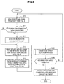
- FIG. 3 is a flowchart illustrating an example of the processing procedure performed by the wireless communication device 100 according to the present embodiment. The process illustrated in FIG. 3 may be started, for example, when the user's instruction to establish a wireless LAN connection with other device is detected.
- the controller 112 instructs the infrared interface 107 (the first wireless I/F) to send a directional signal that may contain identification information of the wireless communication device 100 and protocol information of the wireless LAN interface 108 (step S10).
- the controller 112 determines whether to execute a search for a connection target (step S12).
- the controller 112 when it is determined that a search for a connection target is executed, searches (e.g., the device discovery procedure using Wi-Fi Direct) for a connection target (step S14). This allows one or more of the response side devices to be detected. Meanwhile, when the search for a connection target is completed before the directional signal is sent, the controller 112 may skip the process of searching for a connection target.
- the controller 112 executes a connection target selection process (step S20). Some examples of the detailed procedure of the connection target selection process will be described later. If a connection target is not selected from the connection target selection process, the process returns to step S10 and the above-mentioned process may be repeated (step S40). If a connection target to be connected with the wireless LAN interface 108 is selected from the connection target selection process, the controller 112 instructs the wireless LAN interface 108 to execute a procedure for connecting with the selected connection target (step S42). Thus, a wireless LAN connection with a connection target that is a target determined by the user is established.
- FIG. 4A is a flowchart illustrating a first example of the detailed processing procedure of the connection target selection process shown in FIG. 3 .
- the controller 112 creates a list of response side devices that support a desired service (e.g., transmission of a display video such as Miracast (registered trademark), content reproduction, printing, or data exchange) based on a result obtained from the service inquiry (step S21).
- the controller 112 identifies a device that receives the directional signal sent from the infrared interface 107 among the response side devices (step S22).
- the identified device is a sending source device that sends the service response signal that contains the reception indicator of the directional signal.
- the controller 112 allows a candidate list that displays the identified devices as a candidate for a connection target in a highlighted manner to be displayed on a screen of the display device 104 (step S23).
- the subsequent processing branches depending on the user input. For example, when a connection with a connection target candidate displayed in a highlighted manner is approved by the user (step S25), the controller 112 selects a device displayed in a highlighted manner as a connection target (step S29). If the user specifies another device (step S31), the controller 112 selects the specified other device as a connection target (step S32). On the other hand, if a connection is not approved and other device is not specified, the controller 112 does not select any device as a connection target (step S33).
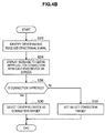
- FIG. 4B is a flowchart illustrating a second example of the detailed processing procedure of the connection target selection process shown in FIG. 3 .
- the controller 112 identifies a device that receives the directional signal sent from the infrared interface 107 among the response side devices based on a result obtained from the service inquiry (step S22).
- the identified device is a sending source device that sends the service response signal that contains the reception indicator of the directional signal.
- the controller 112 allows a message used to obtain an approval for the establishment of a wireless LAN connection to be displayed on a screen of the display device 104 (step S24).
- step S26 the controller 112 selects the device identified based on the result obtained from the service inquiry as a connection target (step S30). On the other hand, if the connection is not approved, the controller 112 does not select any connection target (step S33).
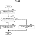
- FIG. 4C is a flowchart illustrating a third example of the detailed processing procedure of the connection target selection process shown in FIG. 3 .
- the controller 112 identifies a device that receives the directional signal sent from the infrared interface 107 among the response side devices based on a result obtained from the service inquiry (step S22).
- the identified device is a sending source device that sends the service response signal that contains the reception indicator of the directional signal.
- the controller 112 determines whether the identified device supports a desired service (step S27). If the identified device supports a desired service, the controller 112 selects automatically the identified device as a connection target (step S30). On the other hand, if the identified device does not support a desired service, the controller 112 dose not select any connection target (step S33).
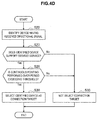
- FIG. 4D is a flowchart illustrating a fourth example of the detailed processing procedure of the connection target selection process shown in FIG. 3 .
- the controller 112 identifies a device that receives the directional signal sent from the infrared interface 107 among the response side devices based on a result obtained from the service inquiry (step S22).
- the identified device is a sending source device that sends the service response signal that contains the reception indicator of the directional signal.
- the controller 112 determines whether the identified device supports a desired service (step S27).
- the controller 112 determines whether the same device is pointed continuously over a period that exceeds a predetermined threshold (step S28).
- the controller 112 selects automatically the identified device as a connection target (step S30). On the other hand, if the identified device does not support a desired service or the same device is not pointed continuously, the controller 112 dose not select any connection target (step S33).
- FIG. 5 is a block diagram illustrating an exemplary configuration of the wireless communication device 150 on the response side.
- the wireless communication device 150 is configured to include a tuner 151, a decoder 152, an input device 153, a display device 154, a loudspeaker 155, a memory 156, an infrared interface 157, a wireless LAN interface 158, a bus 161, and a controller 162.
- the tuner 151 extracts and demodulates a signal of a desired channel from broadcasting signals received via an antenna (not shown) or a cable.
- the decoder 152 decodes the content from the signal demodulated by the tuner 151.
- the input device 153 includes, for example, a button or a switch, and receives an operation performed by the user.
- the display device 154 has a screen such as a liquid crystal display, a plasma display, and an organic light emitting diode display.
- the loudspeaker 155 converts an audio signal outputted from the wireless communication device 150 to sound.
- the memory 156 includes a RAM and ROM. Data and a program executed by the controller 162 described later are stored in the memory 156.
- FIG. 6 is a flowchart illustrating an exemplary processing procedure performed by the wireless communication device 150 according to the present embodiment.
- the infrared interface 157 (the first wireless I/F) waits for the reception of a directional signal from the request side device (step S60). If the directional signal sent from the request side device is received by the infrared interface 157, the controller 162 allows the management information extracted from the directional signal and its time stamp to be stored in the memory 156 (step S62).
- the controller 162 determines whether to execute a search for a connection target (step S64). If it is determined to execute a search for a connection target, the controller 162 executes a search (e.g., the device discovery procedure using Wi-Fi Direct) for a connection target (step S66). For example, when the wireless LAN interface 158 sends a search signal, the request side device that has received the search signal may detect the wireless communication device 150 as the response side device. Even when the wireless LAN interface 158 sends a search response signal as a response to the search signal received from the request side device, the request side device that has received the search response signal may detect the wireless communication device 150 as the response side device.
- a search e.g., the device discovery procedure using Wi-Fi Direct
- the wireless LAN interface 158 (the second wireless I/F) waits for the reception of a service inquiry signal sent from the request side device (step S68).
- the controller 162 collates identification information for identifying a sending source device which has sent the service inquiry signal contained in the service inquiry signal with the identification information obtained from the memory 156 (step S70).
- the controller 162 may perform a collation operation between protocol information as necessary.
- the controller 162 collates the time elapsed from the time at which a directional signal is received to the time at which the service inquiry signal is received with a predetermined threshold using the time stamp stored in the memory 156.
- the controller 162 instructs the wireless LAN interface 158 to send the service response signal to the request side device (step S72). For example, if the comparison between the identification information is successful (or if the time elapsed from the time at which a directional signal is received falls below a threshold), the service response signal to be sent may contain a reception indicator of the directional signal.
- the wireless LAN interface 158 waits for a request for triggering the start of the connection procedure for the wireless LAN connection with the request side device to be received (step S74). If the connection procedure is not started, the controller 162 determines whether the time elapsed from the previous reception of the directional signal falls below a threshold (step S76). If the elapsed time falls below a threshold, the controller 162 allows an indication object, which is used to indicate that the wireless communication device 150 is a connection target candidate for a wireless LAN connection, to be displayed on a screen of the display device 154 (step S78). Meanwhile, if the time elapsed from the previous reception of the directional signal reaches a threshold, the controller 162 erases the management information, which is extracted from the directional signal, and the time stamp from the memory 156 (step S80).
- the controller 162 executes the connection procedure for a wireless LAN connection between the wireless LAN interface 158 and the request side device, and establishes the wireless LAN connection (step S82).
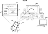
- FIGS. 7A and 7B are diagrams illustrated to describe a first example of a user interface that may be employed in the communication control system 1.
- the user Ua directs the optical axis of the infrared interface 107 in the wireless communication device 100 toward a wireless communication device 150a.
- the wireless communication device 100 has a screen on which a window W1 is displayed.
- the window W1 contains a list L1 of response side devices created based on a result obtained from the service inquiry and a dialog D1.
- an item "DTV01" corresponding to the wireless communication device 150a is displayed in a highlighted manner.
- the dialog D1 indicates the item displayed in a highlighted manner, and asks for the approval of the user Ua to establish a wireless LAN connection with the wireless communication device 150a.
- the user Ua may simply tap the dialog D1 to approve the wireless LAN connection.
- the user Ua changes the orientation of the wireless communication device 100 to direct the optical axis of the infrared interface 107 toward the wireless communication device 150d.
- a window W2 is displayed on a screen of the wireless communication device 100.
- the window W2 contains a list L2 of response side devices created newly based on a result obtained from the service inquiry and a dialog D2.
- an item "NPC04" corresponding to the wireless communication device 150d is displayed in a highlighted manner.
- the dialog D2 indicates the item displayed in a highlighted manner, and asks for the approval of the user Ua to establish a wireless LAN connection with the wireless communication device 150d.
- the user Ua can view the windows W1 and W2 as illustrated in FIGS. 7A and 7B while moving the wireless communication device 100, and thus it is possible for the user to recognize easily a device at which the user is pointing and a device with which a wireless LAN connection is established.
- the items corresponding to a candidate for a connection target determined based on the result obtained from the service inquiry are displayed in a highlighted manner by enlarging a font size and drawing the underline.
- a method of highlighting is not limited to such examples.
- the highlighting of an item may be done by being subjected to coloring, shaping, or moving it for being different from others, or by making other items translucent.
- the item contained in the list may be a character string as illustrated in FIGS. 7A and 7B , or may be other type of object such as an icon or a photograph.
- FIG. 8 is a diagram illustrated to describe a second example of the user interface that may be employed in the communication control system 1. Referring to FIG. 8 , the user Ua directs the optical axis of the infrared interface 107 in the wireless communication device 100 toward the wireless communication device 150a.
- the ANQP query request field 20 includes an information ID (Info ID) 21 in which a vendor specific value is set, a length 22 in which data length is set, an organization identifier (OI) 23 in which a value indicating Wi-Fi Alliance (WFA) is set, and an ANQP query request vendor specific content 24.
- the ANQP query request vendor specific content 24 includes an OUI subtype 31, a service update indicator 32, and a type-length-value (TLV) field 33.
- the TLV field 33 includes a length 34, a service protocol type 35, a service transaction ID 36, and a query data 37.
- a value that may be set in the service protocol type 35 is defined as shown in the following Table 1.
- Table 1 Service Protocol Type Value Meaning 0 All Service Protocol Types 1 Bonjour 2 UPnP (Universal Plug and Play) 3 WS-Discovery (Web Services Dynamic Discovery) 4-254 Reserved 255 Vendor Specific
- the controller 112 of the wireless communication device 100 may set a value "255" indicating that the service inquiry signal SIG 1 contains vendor specific information in the service protocol type 35 of the service inquiry signal SIG 1.
- the controller 112 may set the above-mentioned management information in the service transaction ID 36 or the query data 37.
- the controller 112 may set one value of reserved values "4" to "254" in the service protocol type 35 of the service inquiry signal SIG 1.
- a value to be set in the service inquiry signal SIG1 can be defined as a standard specification, thereby achieving compatibility between vendors.
- FIG. 10 is a diagram illustrated to describe an exemplary format of a service response signal that is sent back from the response side device to the request side device.
- the service response signal SIG2 is the service discovery response in the service discovery procedure using Wi-Fi Direct.
- the service response signal SIG2 includes an MAC header 61, a GAS initial response action frame 62, and an FCS 63.
- the GAS initial response action frame 62 has a format standardized in IEEE802.11u, and includes an ANQP query response field 70.
- a value to be set in the service protocol type 85 may be the same value as the value to be set in the service protocol type 35 described with reference to FIG. 9 .
- the controller 162 of the wireless communication device 150 may set the reception indicator, which indicates that the directional signal is received by the wireless communication device 150, in the status code 87 or the response data 88 of the service response signal SIG2.
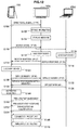
- FIG. 11 is a sequence diagram illustrating a first example of a control procedure in the communication control system 1.
- the wireless communication device 100, the wireless communication device 150a, and the wireless communication device 150d are assumed to be involved.
- the wireless communication device 100 is the request side device.
- the wireless communication device 150a and the wireless communication device 150d are response side devices.
- the wireless communication device 100 sends a directional signal from the infrared interface 107 (step S100).
- the directional signal travels to the direction at which the user is pointing, and is received by the wireless communication device 150a via the infrared interface 157.
- the wireless communication device 150a allows management information contained in the received directional signal to be stored in the memory 156 (step S102).
- the wireless communication device 100 sends a search signal from the wireless LAN interface 108 (step S110).
- the search signal is typically broadcasted to nearby devices, and is received by the wireless communication device 150a and the wireless communication device 150d.
- the wireless communication device 150a which has received the search signal, discovers the existence of the wireless communication device 100 (step S112).
- the wireless communication device 150a sends a search response signal back to the wireless communication device 100 via the wireless LAN interface 158 (step S114).
- the wireless communication device 150d which has received the search signal, discovers the existence of the wireless communication device 100 (step S116).
- the wireless communication device 150d sends a search response signal back to the wireless communication device 100 via the wireless LAN interface 158 (step S118).
- the wireless communication device 100 which has received the search response signal from the wireless communication device 150a and the wireless communication device 150d, discovers the existence of the wireless communication device 150a and the wireless communication device 150d (step S120).
- the wireless communication device 100 sends a service inquiry signal to the wireless communication device 150a via the wireless LAN interface 108 (step S130).
- the wireless communication device 100 sends a service inquiry signal to the wireless communication device 150d via the wireless LAN interface 108 (step S132).
- the service inquiry signal is a unicast signal (in other examples, a service inquiry signal may be a broadcast signal, or the search signal and the service inquiry signal may be integrated into a single signal).
- the wireless communication device 150a which has received the service inquiry signal from the wireless communication device 100, sends a service response signal back to the wireless communication device 100 via the wireless LAN interface 158 (step S134).
- the wireless communication device 150a has received the directional signal from the wireless communication device 100 within the most recent predetermined period (in step S100), and thus the wireless communication device 150a inserts a reception indicator indicating that the directional signal is received into the service response signal.
- the wireless communication device 150d which has received the service inquiry signal from the wireless communication device 100, sends a service response signal back to the wireless communication device 100 via the wireless LAN interface 158 (step S136).
- the wireless communication device 150d does not receive a directional signal within the most recent predetermined period, and thus the wireless communication device 150d does not insert a reception indicator into the service response signal.
- the wireless communication device 100 which has received the service response signal from each of the wireless communication device 150a and the wireless communication device 150d, determines that the wireless communication device 150a is a connection target candidate based on whether each service response signal contains a reception indicator.
- the wireless communication device 100 allows a list of the response side devices that display an item corresponding to the wireless communication device 150a in a highlighted manner to be displayed on a screen (step S140).
- the user approves the wireless LAN connection between the wireless LAN interface 108 and the wireless communication device 150a, for example, by tapping the screen, pressing a predetermined button, or issuing a predetermined voice command (step S142).
- the wireless communication device 100 sends a pre-negotiation request to the wireless communication device 150a via the wireless LAN interface 108 (step S150).
- the wireless communication device 150a which has received the pre-negotiation request, sends a pre-negotiation response back to the wireless communication device 100 via the wireless LAN interface 158 (step S152).
- the wireless communication device 100 sends a pre-negotiation confirmation to the wireless communication device 150a via the wireless LAN interface 108 (step S154).
- the pre-negotiation herein may contain a determination of a group owner (GO) in a case where a wireless LAN connection is established over Wi-Fi Direct.
- the GO is a device acting as an access point.
- the pre-negotiation request, the pre-negotiation response, and the pre-negotiation confirmation may correspond to the GO negotiation request, the GO negotiation response, and the GO negotiation confirm, respectively.
- Such pre-negotiation prior to the start of the connection procedure may be omitted, or other types of pre-negotiation may be performed.
- the connection procedure for the wireless LAN connection is executed between the wireless LAN interface 108 of the wireless communication device 100 and the wireless LAN interface 158 of the wireless communication device 150a (step S160).
- the connection procedure herein may contain a security setting and an exchange of encryption keys.
- the established wireless LAN connection allows data traffic to be transmitted (step S170).
- the wireless communication device 100 may transmit a display video to the wireless communication device 150a via the wireless LAN connection, and a series of images that constitutes the transmitted display video (instead of video, a still image may be transmitted) may be displayed by the display device 154 of the wireless communication device 150a.
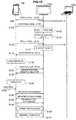
- FIG. 12 is a sequence diagram illustrating a second example of a control procedure in the communication control system 1.
- the wireless communication device 100, the wireless communication device 150a, and the wireless communication device 150d are assumed to be involved.
- the wireless communication device 100 is the request side device.
- the wireless communication device 150a and the wireless communication device 150d are response side devices.
- the wireless communication device 100 sends a search signal from the wireless LAN interface 108 (step S110).
- the search signal is typically broadcasted to nearby devices, and is received by the wireless communication device 150a and the wireless communication device 150d.
- the wireless communication device 150a which has received the search signal, discovers the existence of the wireless communication device 100 (step S112).
- the wireless communication device 150a sends a search response signal back to the wireless communication device 100 via the wireless LAN interface 158 (step S114).
- the wireless communication device 150d which has received the search signal, discovers the existence of the wireless communication device 100 (step S116).
- the wireless communication device 150d sends a search response signal back to the wireless communication device 100 via the wireless LAN interface 158 (step S118).
- the wireless communication device 100 which has received the search response signal from the wireless communication device 150a and the wireless communication device 150d, discovers the existence of the wireless communication device 150a and the wireless communication device 150d (step S120).
- the wireless communication device 100 sends a service inquiry signal to the wireless communication device 150a via the wireless LAN interface 108 (step S130).
- the wireless communication device 100 sends a service inquiry signal to the wireless communication device 150d via the wireless LAN interface 108 (step S132).
- the wireless communication device 150a which has received the service inquiry signal from the wireless communication device 100, sends a service response signal back to the wireless communication device 100 via the wireless LAN interface 158 (step S134).
- the wireless communication device 150a has received the directional signal from the wireless communication device 100 within the most recent predetermined period, and thus the wireless communication device 150a inserts a reception indicator indicating that the directional signal is received into the service response signal.
- the wireless communication device 150d which has received the service inquiry signal from the wireless communication device 100, sends a service response signal back to the wireless communication device 100 via the wireless LAN interface 158 (step S136).
- the wireless communication device 150d does not insert a reception indicator into the service response signal.
- a connection target which is determined based on the reception indicator contained in the second wireless signal in the list of devices connectable with the second wireless interface, may be displayed on a screen used for the user to specify a connection target in a highlighted manner.
- the user can easily know which item displayed corresponds to which device and know a device at which the user is currently pointing.
- the user can start accurately a wireless connection with a connection target, for example, by just performing a simple operation such as tapping for the approval of connection.
- the wireless connection with a connection target which is determined based on the reception indicator contained in the second wireless signal, is established automatically without waiting for the user's approval.
- the automatic connection may be performed when the plurality of second wireless signals received from the same sending source device over a predetermined number of times or period contain continuously the above-mentioned reception indicator.
- Such configuration makes it possible to reduce the risk of establishing erroneously the wireless connection with a device that is not a target. It is possible to implement a special user interface that is pointing at the same device for a period of time to select a connection target.
- the second wireless signal which contains a reception indicator indicating that the first wireless signal is received, is sent to the request side device that searches for a target to be connected wirelessly via the second wireless interface for the wireless connection.
- the notification that the user is pointing at the response side device as a connection target can be performed from the response side device to the request side device without having the user to perform other operations than the pointing operation.
- the reception indicator may be inserted into the second wireless signal under a condition that the time elapsed from the previous reception of the first wireless signal falls below a threshold.
- a change in the direction of the request side device by the user allows a response side device sending a reception indicator to be dynamically changed to another device.
- the reception indicator may be inserted into the second wireless signal, only when the second wireless signal is sent as a response to the inquiry from the request side device and the identification information of the device having submitted the inquiry matches the identification information contained in the first wireless signal.
- the one-to-one relationship between the request side device and the response side device that are involved in the pointing operation becomes apparent, and thus an appropriate peer-to-peer connection can be established even in situations where there are many devices.
- a series of processes performed by each apparatus described herein are typically implemented using software.
- a program included in the software that implements the series of processes is stored in advance, for example, in a storage medium (non-transitory medium) that is provided inside or outside each apparatus.
- Each program may be read into RAM upon execution and be executed through a processor such as CPU.
- the technology according to the present disclosure may be implemented as a one-chip module in which a processor for executing such program, a memory having the program stored therein, and a related circuit are integrated.
- present technology may also be configured as below.
Landscapes
- Engineering & Computer Science (AREA)
- Computer Networks & Wireless Communication (AREA)
- Signal Processing (AREA)
- Automation & Control Theory (AREA)
- Human Computer Interaction (AREA)
- Physics & Mathematics (AREA)
- General Physics & Mathematics (AREA)
- Mobile Radio Communication Systems (AREA)
- Telephone Function (AREA)
- Transceivers (AREA)
- Selective Calling Equipment (AREA)
Applications Claiming Priority (2)
| Application Number | Priority Date | Filing Date | Title |
|---|---|---|---|
| JP2013128614 | 2013-06-19 | ||
| PCT/JP2014/062883 WO2014203657A1 (ja) | 2013-06-19 | 2014-05-14 | 無線通信装置及び通信制御装置 |
Publications (3)
| Publication Number | Publication Date |
|---|---|
| EP3013079A1 true EP3013079A1 (de) | 2016-04-27 |
| EP3013079A4 EP3013079A4 (de) | 2017-03-01 |
| EP3013079B1 EP3013079B1 (de) | 2021-08-11 |
Family
ID=52104399
Family Applications (1)
| Application Number | Title | Priority Date | Filing Date |
|---|---|---|---|
| EP14814278.9A Active EP3013079B1 (de) | 2013-06-19 | 2014-05-14 | Drahtloskommunikationsvorrichtung und kommunikationssteuerungsverfahren |
Country Status (10)
| Country | Link |
|---|---|
| US (1) | US10085290B2 (de) |
| EP (1) | EP3013079B1 (de) |
| JP (1) | JP6459965B2 (de) |
| CN (1) | CN105325018B (de) |
| MX (1) | MX358809B (de) |
| RU (1) | RU2665886C2 (de) |
| SG (1) | SG11201510158WA (de) |
| TW (1) | TWI634805B (de) |
| WO (1) | WO2014203657A1 (de) |
| ZA (1) | ZA201508440B (de) |
Cited By (1)
| Publication number | Priority date | Publication date | Assignee | Title |
|---|---|---|---|---|
| DE102016100669A1 (de) * | 2016-01-15 | 2017-07-20 | Technisat Digital Gmbh | Anordnung, Vorrichtung, Bedienteil sowie Verfahren zum Bedienen |
Families Citing this family (10)
| Publication number | Priority date | Publication date | Assignee | Title |
|---|---|---|---|---|
| JP6312369B2 (ja) * | 2013-04-26 | 2018-04-18 | キヤノン株式会社 | 通信装置、通信装置の制御方法、プログラム |
| JP6584106B2 (ja) * | 2015-03-19 | 2019-10-02 | キヤノン株式会社 | 通信機器およびその制御方法、プログラム |
| WO2017006528A1 (ja) | 2015-07-07 | 2017-01-12 | パナソニックIpマネジメント株式会社 | 通信システム、送信端末および受信端末 |
| JP6730790B2 (ja) * | 2015-09-15 | 2020-07-29 | キヤノン株式会社 | 通信装置およびその制御方法ならびにプログラム |
| JP2017175283A (ja) * | 2016-03-22 | 2017-09-28 | コニカミノルタ株式会社 | 会議システム、テレビ会議装置およびプログラム |
| KR102516019B1 (ko) * | 2017-09-11 | 2023-03-30 | 삼성전자주식회사 | 외부 전자 장치와 통신하는 전자 장치 및 방법 |
| JP7118764B2 (ja) * | 2018-06-20 | 2022-08-16 | キヤノン株式会社 | 通信装置、制御方法、およびプログラム |
| JP7154833B2 (ja) | 2018-06-20 | 2022-10-18 | キヤノン株式会社 | 通信装置、通信方法、およびプログラム |
| KR102689698B1 (ko) * | 2019-01-03 | 2024-07-31 | 삼성전자주식회사 | 디스플레이 장치 및 그 제어 방법 |
| KR20230036848A (ko) * | 2021-09-08 | 2023-03-15 | 삼성전자주식회사 | 적어도 하나의 uwb 장치를 제어하기 위한 사용자 경험을 제공하는 전자 장치 및 그 제어 방법 |
Family Cites Families (23)
| Publication number | Priority date | Publication date | Assignee | Title |
|---|---|---|---|---|
| RU2127019C1 (ru) * | 1997-08-01 | 1999-02-27 | Рыжов Владимир Александрович | Пульт дистанционного управления устройствами бытовой техники и компьютерными системами |
| JP3958910B2 (ja) * | 1999-12-28 | 2007-08-15 | 三井金属鉱業株式会社 | 電子部品実装用フィルムキャリアテープのメッキ処理方法および電子部品実装用フィルムキャリアテープのメッキ処理装置 |
| JP3906200B2 (ja) | 2003-11-27 | 2007-04-18 | インターナショナル・ビジネス・マシーンズ・コーポレーション | 通信装置、通信システム、通信方法、プログラム、及び記録媒体 |
| JP4293108B2 (ja) * | 2004-10-14 | 2009-07-08 | ソニー株式会社 | リモート・コントロール・システム及びリモート・コントロール方法、リモート・コントローラ、並びに電子機器 |
| JP2006165831A (ja) * | 2004-12-06 | 2006-06-22 | Yaskawa Electric Corp | コントローラ、無線操作端末および無線通信チャネル接続方法 |
| DE102006018238A1 (de) * | 2005-04-20 | 2007-03-29 | Logitech Europe S.A. | System und Verfahren zur adaptiven Programmierung einer Fernbedienung |
| JP4483788B2 (ja) * | 2005-05-09 | 2010-06-16 | ソニー株式会社 | リモコン・システム、リモート・コマンダ及びリモコン操作方法、リモコン制御対象機器、並びにコンピュータ・システム |
| JP2007189348A (ja) * | 2006-01-11 | 2007-07-26 | Fujifilm Corp | 通信システム、通信ホスト、通信端末および通信方法 |
| CN100507969C (zh) * | 2006-08-15 | 2009-07-01 | 何进 | 选择性智能遥控系统及方法 |
| JP4941087B2 (ja) | 2007-05-14 | 2012-05-30 | ソニー株式会社 | 無線通信端末 |
| US8103241B2 (en) * | 2007-12-07 | 2012-01-24 | Roche Diagnostics Operations, Inc. | Method and system for wireless device communication |
| US9088663B2 (en) * | 2008-04-18 | 2015-07-21 | Universal Electronics Inc. | System for appliance control via a network |
| US20150082355A1 (en) * | 2010-04-11 | 2015-03-19 | Mark Tiddens | Method and Apparatus for Interfacing Broadcast Television and Video Displayed Media with Networked Components |
| US20110252443A1 (en) | 2010-04-11 | 2011-10-13 | Mark Tiddens | Method and Apparatus for Interfacing Broadcast Television and Video Display with Computer Network |
| US8150384B2 (en) * | 2010-06-16 | 2012-04-03 | Qualcomm Incorporated | Methods and apparatuses for gesture based remote control |
| TWI399083B (zh) * | 2010-07-28 | 2013-06-11 | Compal Communication Inc | 具遙控功能之無線通訊系統及其無線通訊模組 |
| JP5671879B2 (ja) * | 2010-08-24 | 2015-02-18 | ソニー株式会社 | 無線通信装置、プログラム、無線通信方法、および無線通信システム |
| JP5664273B2 (ja) * | 2011-01-21 | 2015-02-04 | ソニー株式会社 | 無線通信装置、プログラム、および無線通信システム |
| JP6154098B2 (ja) | 2011-03-08 | 2017-06-28 | ソニー株式会社 | 無線通信装置、無線通信方法、及び無線通信システム |
| US9167508B2 (en) * | 2011-03-08 | 2015-10-20 | Sony Corporation | Wireless communication apparatus, wireless communication method, and wireless communication system for providing improved wireless communication |
| KR101826327B1 (ko) * | 2011-08-02 | 2018-02-07 | 삼성전자주식회사 | 와이파이 피투피 그룹의 생성 방법 |
| KR20130060556A (ko) * | 2011-11-30 | 2013-06-10 | 삼성전자주식회사 | 휴대단말기의 디바이스 연결 장치 및 방법 |
| KR20150098619A (ko) * | 2012-12-17 | 2015-08-28 | 엘지전자 주식회사 | 무선랜 시스템에서 서비스 발견 방법 및 장치 |
-
2014
- 2014-05-14 MX MX2015017085A patent/MX358809B/es active IP Right Grant
- 2014-05-14 EP EP14814278.9A patent/EP3013079B1/de active Active
- 2014-05-14 SG SG11201510158WA patent/SG11201510158WA/en unknown
- 2014-05-14 US US14/890,675 patent/US10085290B2/en active Active
- 2014-05-14 WO PCT/JP2014/062883 patent/WO2014203657A1/ja not_active Ceased
- 2014-05-14 CN CN201480033351.0A patent/CN105325018B/zh not_active Expired - Fee Related
- 2014-05-14 RU RU2015153355A patent/RU2665886C2/ru active
- 2014-05-14 JP JP2015522666A patent/JP6459965B2/ja not_active Expired - Fee Related
- 2014-05-15 TW TW103117145A patent/TWI634805B/zh not_active IP Right Cessation
-
2015
- 2015-11-16 ZA ZA2015/08440A patent/ZA201508440B/en unknown
Cited By (1)
| Publication number | Priority date | Publication date | Assignee | Title |
|---|---|---|---|---|
| DE102016100669A1 (de) * | 2016-01-15 | 2017-07-20 | Technisat Digital Gmbh | Anordnung, Vorrichtung, Bedienteil sowie Verfahren zum Bedienen |
Also Published As
| Publication number | Publication date |
|---|---|
| US20160135233A1 (en) | 2016-05-12 |
| US10085290B2 (en) | 2018-09-25 |
| SG11201510158WA (en) | 2016-01-28 |
| TW201513711A (zh) | 2015-04-01 |
| JPWO2014203657A1 (ja) | 2017-02-23 |
| JP6459965B2 (ja) | 2019-01-30 |
| WO2014203657A1 (ja) | 2014-12-24 |
| ZA201508440B (en) | 2016-08-31 |
| RU2015153355A (ru) | 2017-06-16 |
| TWI634805B (zh) | 2018-09-01 |
| EP3013079B1 (de) | 2021-08-11 |
| CN105325018B (zh) | 2019-10-18 |
| MX358809B (es) | 2018-09-05 |
| EP3013079A4 (de) | 2017-03-01 |
| MX2015017085A (es) | 2016-04-11 |
| CN105325018A (zh) | 2016-02-10 |
| RU2015153355A3 (de) | 2018-03-05 |
| RU2665886C2 (ru) | 2018-09-04 |
Similar Documents
| Publication | Publication Date | Title |
|---|---|---|
| EP3013079B1 (de) | Drahtloskommunikationsvorrichtung und kommunikationssteuerungsverfahren | |
| KR101851532B1 (ko) | 자동 페어링을 위한 단말 장치, 원격 제어 장치 및 방법 | |
| JP5937095B2 (ja) | デジタル機器における無線ネットワークの連結方法及びその装置 | |
| KR101562565B1 (ko) | 전기장을 이용한 데이터 송수신 방법 및 이를 위한 장치 | |
| US9479635B2 (en) | Apparatus and method for motion detecting in mobile communication terminal | |
| US20020037699A1 (en) | Radio communication system and electronic device search method | |
| KR100744297B1 (ko) | 블루투스 디바이스를 검색 및 연결하기 위한 장치 및 방법 | |
| CN108882338B (zh) | 信息处理装置和控制方法 | |
| TW201352051A (zh) | 通訊裝置、通訊方法、程式及通訊系統 | |
| KR20110053187A (ko) | 무선 통신 장치, 무선 통신 시스템, 프로그램 및 무선 통신 방법 | |
| JP5642464B2 (ja) | 情報処理装置 | |
| EP2949138B1 (de) | Kommunikationsvorrichtung, verfahren zur steuerung davon und programm | |
| EP2408223B1 (de) | Zugangspunkt und verfahren zum anschluss einer drahtlosen kommunikation | |
| WO2015098162A1 (ja) | 車載装置及び車載装置の制御方法 | |
| US20080268814A1 (en) | Radio Communication Device and Radio Communication Method | |
| KR20090112101A (ko) | 방송수신장치와 무선 인터페이스 장치 및 그 제어방법 | |
| JP2008098893A (ja) | 無線通信モジュール、及び無線通信システム | |
| KR101766248B1 (ko) | 디스플레이시스템, 디스플레이장치 및 그 제어방법 | |
| US20110099606A1 (en) | Apparatus and method for connecting with access point in mobile terminal | |
| US10057756B2 (en) | Terminal detection method and communication device | |
| JP2018125705A (ja) | 通信接続方法、通信接続装置、通信システム及び通信接続プログラム | |
| JP2014022907A (ja) | 無線通信システム、無線接続方法、電子機器、無線端末およびプログラム | |
| JP2010074768A (ja) | 無線簡易設定システム、無線簡易設定方法、及び無線簡易設定プログラム |
Legal Events
| Date | Code | Title | Description |
|---|---|---|---|
| PUAI | Public reference made under article 153(3) epc to a published international application that has entered the european phase |
Free format text: ORIGINAL CODE: 0009012 |
|
| 17P | Request for examination filed |
Effective date: 20151130 |
|
| AK | Designated contracting states |
Kind code of ref document: A1 Designated state(s): AL AT BE BG CH CY CZ DE DK EE ES FI FR GB GR HR HU IE IS IT LI LT LU LV MC MK MT NL NO PL PT RO RS SE SI SK SM TR |
|
| AX | Request for extension of the european patent |
Extension state: BA ME |
|
| DAX | Request for extension of the european patent (deleted) | ||
| RIC1 | Information provided on ipc code assigned before grant |
Ipc: H04Q 9/00 20060101ALI20161018BHEP Ipc: H04W 88/06 20090101ALI20161018BHEP Ipc: H04W 76/02 20090101ALI20161018BHEP Ipc: H04W 8/00 20090101AFI20161018BHEP Ipc: H04W 4/00 20090101ALI20161018BHEP Ipc: H04W 88/02 20090101ALI20161018BHEP |
|
| A4 | Supplementary search report drawn up and despatched |
Effective date: 20170127 |
|
| RIC1 | Information provided on ipc code assigned before grant |
Ipc: H04Q 9/00 20060101ALI20170123BHEP Ipc: H04W 88/06 20090101ALI20170123BHEP Ipc: H04W 88/02 20090101ALI20170123BHEP Ipc: H04W 4/00 20090101ALI20170123BHEP Ipc: H04W 76/02 20090101ALI20170123BHEP Ipc: H04W 8/00 20090101AFI20170123BHEP |
|
| STAA | Information on the status of an ep patent application or granted ep patent |
Free format text: STATUS: EXAMINATION IS IN PROGRESS |
|
| 17Q | First examination report despatched |
Effective date: 20190425 |
|
| GRAP | Despatch of communication of intention to grant a patent |
Free format text: ORIGINAL CODE: EPIDOSNIGR1 |
|
| STAA | Information on the status of an ep patent application or granted ep patent |
Free format text: STATUS: GRANT OF PATENT IS INTENDED |
|
| RIC1 | Information provided on ipc code assigned before grant |
Ipc: H04W 8/00 20090101AFI20210211BHEP Ipc: H04W 88/06 20090101ALI20210211BHEP Ipc: H04W 88/02 20090101ALI20210211BHEP Ipc: H04Q 9/00 20060101ALI20210211BHEP Ipc: H04W 4/00 20180101ALI20210211BHEP |
|
| INTG | Intention to grant announced |
Effective date: 20210304 |
|
| GRAS | Grant fee paid |
Free format text: ORIGINAL CODE: EPIDOSNIGR3 |
|
| GRAA | (expected) grant |
Free format text: ORIGINAL CODE: 0009210 |
|
| STAA | Information on the status of an ep patent application or granted ep patent |
Free format text: STATUS: THE PATENT HAS BEEN GRANTED |
|
| RAP3 | Party data changed (applicant data changed or rights of an application transferred) |
Owner name: SONY GROUP CORPORATION |
|
| AK | Designated contracting states |
Kind code of ref document: B1 Designated state(s): AL AT BE BG CH CY CZ DE DK EE ES FI FR GB GR HR HU IE IS IT LI LT LU LV MC MK MT NL NO PL PT RO RS SE SI SK SM TR |
|
| REG | Reference to a national code |
Ref country code: CH Ref legal event code: EP |
|
| REG | Reference to a national code |
Ref country code: DE Ref legal event code: R096 Ref document number: 602014079402 Country of ref document: DE |
|
| REG | Reference to a national code |
Ref country code: IE Ref legal event code: FG4D Ref country code: AT Ref legal event code: REF Ref document number: 1420643 Country of ref document: AT Kind code of ref document: T Effective date: 20210915 |
|
| REG | Reference to a national code |
Ref country code: NL Ref legal event code: FP |
|
| REG | Reference to a national code |
Ref country code: LT Ref legal event code: MG9D |
|
| REG | Reference to a national code |
Ref country code: AT Ref legal event code: MK05 Ref document number: 1420643 Country of ref document: AT Kind code of ref document: T Effective date: 20210811 |
|
| PG25 | Lapsed in a contracting state [announced via postgrant information from national office to epo] |
Ref country code: HR Free format text: LAPSE BECAUSE OF FAILURE TO SUBMIT A TRANSLATION OF THE DESCRIPTION OR TO PAY THE FEE WITHIN THE PRESCRIBED TIME-LIMIT Effective date: 20210811 Ref country code: SE Free format text: LAPSE BECAUSE OF FAILURE TO SUBMIT A TRANSLATION OF THE DESCRIPTION OR TO PAY THE FEE WITHIN THE PRESCRIBED TIME-LIMIT Effective date: 20210811 Ref country code: RS Free format text: LAPSE BECAUSE OF FAILURE TO SUBMIT A TRANSLATION OF THE DESCRIPTION OR TO PAY THE FEE WITHIN THE PRESCRIBED TIME-LIMIT Effective date: 20210811 Ref country code: NO Free format text: LAPSE BECAUSE OF FAILURE TO SUBMIT A TRANSLATION OF THE DESCRIPTION OR TO PAY THE FEE WITHIN THE PRESCRIBED TIME-LIMIT Effective date: 20211111 Ref country code: PT Free format text: LAPSE BECAUSE OF FAILURE TO SUBMIT A TRANSLATION OF THE DESCRIPTION OR TO PAY THE FEE WITHIN THE PRESCRIBED TIME-LIMIT Effective date: 20211213 Ref country code: ES Free format text: LAPSE BECAUSE OF FAILURE TO SUBMIT A TRANSLATION OF THE DESCRIPTION OR TO PAY THE FEE WITHIN THE PRESCRIBED TIME-LIMIT Effective date: 20210811 Ref country code: FI Free format text: LAPSE BECAUSE OF FAILURE TO SUBMIT A TRANSLATION OF THE DESCRIPTION OR TO PAY THE FEE WITHIN THE PRESCRIBED TIME-LIMIT Effective date: 20210811 Ref country code: BG Free format text: LAPSE BECAUSE OF FAILURE TO SUBMIT A TRANSLATION OF THE DESCRIPTION OR TO PAY THE FEE WITHIN THE PRESCRIBED TIME-LIMIT Effective date: 20211111 Ref country code: AT Free format text: LAPSE BECAUSE OF FAILURE TO SUBMIT A TRANSLATION OF THE DESCRIPTION OR TO PAY THE FEE WITHIN THE PRESCRIBED TIME-LIMIT Effective date: 20210811 Ref country code: LT Free format text: LAPSE BECAUSE OF FAILURE TO SUBMIT A TRANSLATION OF THE DESCRIPTION OR TO PAY THE FEE WITHIN THE PRESCRIBED TIME-LIMIT Effective date: 20210811 |
|
| PG25 | Lapsed in a contracting state [announced via postgrant information from national office to epo] |
Ref country code: PL Free format text: LAPSE BECAUSE OF FAILURE TO SUBMIT A TRANSLATION OF THE DESCRIPTION OR TO PAY THE FEE WITHIN THE PRESCRIBED TIME-LIMIT Effective date: 20210811 Ref country code: LV Free format text: LAPSE BECAUSE OF FAILURE TO SUBMIT A TRANSLATION OF THE DESCRIPTION OR TO PAY THE FEE WITHIN THE PRESCRIBED TIME-LIMIT Effective date: 20210811 Ref country code: GR Free format text: LAPSE BECAUSE OF FAILURE TO SUBMIT A TRANSLATION OF THE DESCRIPTION OR TO PAY THE FEE WITHIN THE PRESCRIBED TIME-LIMIT Effective date: 20211112 |
|
| PG25 | Lapsed in a contracting state [announced via postgrant information from national office to epo] |
Ref country code: DK Free format text: LAPSE BECAUSE OF FAILURE TO SUBMIT A TRANSLATION OF THE DESCRIPTION OR TO PAY THE FEE WITHIN THE PRESCRIBED TIME-LIMIT Effective date: 20210811 |
|
| REG | Reference to a national code |
Ref country code: DE Ref legal event code: R097 Ref document number: 602014079402 Country of ref document: DE |
|
| PG25 | Lapsed in a contracting state [announced via postgrant information from national office to epo] |
Ref country code: SM Free format text: LAPSE BECAUSE OF FAILURE TO SUBMIT A TRANSLATION OF THE DESCRIPTION OR TO PAY THE FEE WITHIN THE PRESCRIBED TIME-LIMIT Effective date: 20210811 Ref country code: SK Free format text: LAPSE BECAUSE OF FAILURE TO SUBMIT A TRANSLATION OF THE DESCRIPTION OR TO PAY THE FEE WITHIN THE PRESCRIBED TIME-LIMIT Effective date: 20210811 Ref country code: RO Free format text: LAPSE BECAUSE OF FAILURE TO SUBMIT A TRANSLATION OF THE DESCRIPTION OR TO PAY THE FEE WITHIN THE PRESCRIBED TIME-LIMIT Effective date: 20210811 Ref country code: EE Free format text: LAPSE BECAUSE OF FAILURE TO SUBMIT A TRANSLATION OF THE DESCRIPTION OR TO PAY THE FEE WITHIN THE PRESCRIBED TIME-LIMIT Effective date: 20210811 Ref country code: CZ Free format text: LAPSE BECAUSE OF FAILURE TO SUBMIT A TRANSLATION OF THE DESCRIPTION OR TO PAY THE FEE WITHIN THE PRESCRIBED TIME-LIMIT Effective date: 20210811 Ref country code: AL Free format text: LAPSE BECAUSE OF FAILURE TO SUBMIT A TRANSLATION OF THE DESCRIPTION OR TO PAY THE FEE WITHIN THE PRESCRIBED TIME-LIMIT Effective date: 20210811 |
|
| PLBE | No opposition filed within time limit |
Free format text: ORIGINAL CODE: 0009261 |
|
| STAA | Information on the status of an ep patent application or granted ep patent |
Free format text: STATUS: NO OPPOSITION FILED WITHIN TIME LIMIT |
|
| PGFP | Annual fee paid to national office [announced via postgrant information from national office to epo] |
Ref country code: NL Payment date: 20220420 Year of fee payment: 9 |
|
| 26N | No opposition filed |
Effective date: 20220512 |
|
| PG25 | Lapsed in a contracting state [announced via postgrant information from national office to epo] |
Ref country code: IT Free format text: LAPSE BECAUSE OF FAILURE TO SUBMIT A TRANSLATION OF THE DESCRIPTION OR TO PAY THE FEE WITHIN THE PRESCRIBED TIME-LIMIT Effective date: 20210811 |
|
| PGFP | Annual fee paid to national office [announced via postgrant information from national office to epo] |
Ref country code: FR Payment date: 20220421 Year of fee payment: 9 Ref country code: DE Payment date: 20220420 Year of fee payment: 9 |
|
| PG25 | Lapsed in a contracting state [announced via postgrant information from national office to epo] |
Ref country code: SI Free format text: LAPSE BECAUSE OF FAILURE TO SUBMIT A TRANSLATION OF THE DESCRIPTION OR TO PAY THE FEE WITHIN THE PRESCRIBED TIME-LIMIT Effective date: 20210811 |
|
| REG | Reference to a national code |
Ref country code: CH Ref legal event code: PL |
|
| REG | Reference to a national code |
Ref country code: BE Ref legal event code: MM Effective date: 20220531 |
|
| GBPC | Gb: european patent ceased through non-payment of renewal fee |
Effective date: 20220514 |
|
| PG25 | Lapsed in a contracting state [announced via postgrant information from national office to epo] |
Ref country code: MC Free format text: LAPSE BECAUSE OF FAILURE TO SUBMIT A TRANSLATION OF THE DESCRIPTION OR TO PAY THE FEE WITHIN THE PRESCRIBED TIME-LIMIT Effective date: 20210811 Ref country code: LU Free format text: LAPSE BECAUSE OF NON-PAYMENT OF DUE FEES Effective date: 20220514 Ref country code: LI Free format text: LAPSE BECAUSE OF NON-PAYMENT OF DUE FEES Effective date: 20220531 Ref country code: CH Free format text: LAPSE BECAUSE OF NON-PAYMENT OF DUE FEES Effective date: 20220531 |
|
| PG25 | Lapsed in a contracting state [announced via postgrant information from national office to epo] |
Ref country code: IE Free format text: LAPSE BECAUSE OF NON-PAYMENT OF DUE FEES Effective date: 20220514 |
|
| PG25 | Lapsed in a contracting state [announced via postgrant information from national office to epo] |
Ref country code: GB Free format text: LAPSE BECAUSE OF NON-PAYMENT OF DUE FEES Effective date: 20220514 Ref country code: BE Free format text: LAPSE BECAUSE OF NON-PAYMENT OF DUE FEES Effective date: 20220531 |
|
| REG | Reference to a national code |
Ref country code: DE Ref legal event code: R119 Ref document number: 602014079402 Country of ref document: DE |
|
| REG | Reference to a national code |
Ref country code: NL Ref legal event code: MM Effective date: 20230601 |
|
| PG25 | Lapsed in a contracting state [announced via postgrant information from national office to epo] |
Ref country code: NL Free format text: LAPSE BECAUSE OF NON-PAYMENT OF DUE FEES Effective date: 20230601 |
|
| PG25 | Lapsed in a contracting state [announced via postgrant information from national office to epo] |
Ref country code: HU Free format text: LAPSE BECAUSE OF FAILURE TO SUBMIT A TRANSLATION OF THE DESCRIPTION OR TO PAY THE FEE WITHIN THE PRESCRIBED TIME-LIMIT; INVALID AB INITIO Effective date: 20140514 |
|
| PG25 | Lapsed in a contracting state [announced via postgrant information from national office to epo] |
Ref country code: MK Free format text: LAPSE BECAUSE OF FAILURE TO SUBMIT A TRANSLATION OF THE DESCRIPTION OR TO PAY THE FEE WITHIN THE PRESCRIBED TIME-LIMIT Effective date: 20210811 Ref country code: DE Free format text: LAPSE BECAUSE OF NON-PAYMENT OF DUE FEES Effective date: 20231201 Ref country code: CY Free format text: LAPSE BECAUSE OF FAILURE TO SUBMIT A TRANSLATION OF THE DESCRIPTION OR TO PAY THE FEE WITHIN THE PRESCRIBED TIME-LIMIT Effective date: 20210811 |
|
| PG25 | Lapsed in a contracting state [announced via postgrant information from national office to epo] |
Ref country code: FR Free format text: LAPSE BECAUSE OF NON-PAYMENT OF DUE FEES Effective date: 20230531 |
|
| PG25 | Lapsed in a contracting state [announced via postgrant information from national office to epo] |
Ref country code: TR Free format text: LAPSE BECAUSE OF FAILURE TO SUBMIT A TRANSLATION OF THE DESCRIPTION OR TO PAY THE FEE WITHIN THE PRESCRIBED TIME-LIMIT Effective date: 20210811 |
|
| PG25 | Lapsed in a contracting state [announced via postgrant information from national office to epo] |
Ref country code: MT Free format text: LAPSE BECAUSE OF FAILURE TO SUBMIT A TRANSLATION OF THE DESCRIPTION OR TO PAY THE FEE WITHIN THE PRESCRIBED TIME-LIMIT Effective date: 20210811 |