EP3013204B1 - Aspirateur avec filtre électrostatique - Google Patents
Aspirateur avec filtre électrostatique Download PDFInfo
- Publication number
- EP3013204B1 EP3013204B1 EP14744890.6A EP14744890A EP3013204B1 EP 3013204 B1 EP3013204 B1 EP 3013204B1 EP 14744890 A EP14744890 A EP 14744890A EP 3013204 B1 EP3013204 B1 EP 3013204B1
- Authority
- EP
- European Patent Office
- Prior art keywords
- air
- vacuum cleaner
- passageway
- dust
- electrode arrangement
- Prior art date
- Legal status (The legal status is an assumption and is not a legal conclusion. Google has not performed a legal analysis and makes no representation as to the accuracy of the status listed.)
- Not-in-force
Links
- 239000000428 dust Substances 0.000 claims description 51
- 239000011248 coating agent Substances 0.000 claims description 13
- 238000000576 coating method Methods 0.000 claims description 13
- 239000002245 particle Substances 0.000 description 30
- 239000000758 substrate Substances 0.000 description 6
- 238000000034 method Methods 0.000 description 5
- 230000000694 effects Effects 0.000 description 4
- 230000008569 process Effects 0.000 description 4
- 230000005684 electric field Effects 0.000 description 3
- 238000000605 extraction Methods 0.000 description 3
- 239000000463 material Substances 0.000 description 3
- 230000009286 beneficial effect Effects 0.000 description 2
- 239000003990 capacitor Substances 0.000 description 2
- 239000004020 conductor Substances 0.000 description 2
- 238000001914 filtration Methods 0.000 description 2
- 230000005641 tunneling Effects 0.000 description 2
- 241000894006 Bacteria Species 0.000 description 1
- 238000009825 accumulation Methods 0.000 description 1
- 230000009471 action Effects 0.000 description 1
- 229910010293 ceramic material Inorganic materials 0.000 description 1
- 238000004140 cleaning Methods 0.000 description 1
- 230000001419 dependent effect Effects 0.000 description 1
- 239000006185 dispersion Substances 0.000 description 1
- 238000005516 engineering process Methods 0.000 description 1
- 239000012530 fluid Substances 0.000 description 1
- 231100000206 health hazard Toxicity 0.000 description 1
- 230000006872 improvement Effects 0.000 description 1
- 239000011810 insulating material Substances 0.000 description 1
- 244000005700 microbiome Species 0.000 description 1
- 238000006386 neutralization reaction Methods 0.000 description 1
- 230000037361 pathway Effects 0.000 description 1
- 230000000750 progressive effect Effects 0.000 description 1
- 238000005086 pumping Methods 0.000 description 1
- 230000009467 reduction Effects 0.000 description 1
- 230000000717 retained effect Effects 0.000 description 1
- 238000012163 sequencing technique Methods 0.000 description 1
- 238000004659 sterilization and disinfection Methods 0.000 description 1
- 239000002699 waste material Substances 0.000 description 1
Images
Classifications
-
- A—HUMAN NECESSITIES
- A47—FURNITURE; DOMESTIC ARTICLES OR APPLIANCES; COFFEE MILLS; SPICE MILLS; SUCTION CLEANERS IN GENERAL
- A47L—DOMESTIC WASHING OR CLEANING; SUCTION CLEANERS IN GENERAL
- A47L9/00—Details or accessories of suction cleaners, e.g. mechanical means for controlling the suction or for effecting pulsating action; Storing devices specially adapted to suction cleaners or parts thereof; Carrying-vehicles specially adapted for suction cleaners
- A47L9/10—Filters; Dust separators; Dust removal; Automatic exchange of filters
- A47L9/12—Dry filters
-
- A—HUMAN NECESSITIES
- A47—FURNITURE; DOMESTIC ARTICLES OR APPLIANCES; COFFEE MILLS; SPICE MILLS; SUCTION CLEANERS IN GENERAL
- A47L—DOMESTIC WASHING OR CLEANING; SUCTION CLEANERS IN GENERAL
- A47L5/00—Structural features of suction cleaners
- A47L5/12—Structural features of suction cleaners with power-driven air-pumps or air-compressors, e.g. driven by motor vehicle engine vacuum
- A47L5/22—Structural features of suction cleaners with power-driven air-pumps or air-compressors, e.g. driven by motor vehicle engine vacuum with rotary fans
-
- A—HUMAN NECESSITIES
- A47—FURNITURE; DOMESTIC ARTICLES OR APPLIANCES; COFFEE MILLS; SPICE MILLS; SUCTION CLEANERS IN GENERAL
- A47L—DOMESTIC WASHING OR CLEANING; SUCTION CLEANERS IN GENERAL
- A47L9/00—Details or accessories of suction cleaners, e.g. mechanical means for controlling the suction or for effecting pulsating action; Storing devices specially adapted to suction cleaners or parts thereof; Carrying-vehicles specially adapted for suction cleaners
- A47L9/10—Filters; Dust separators; Dust removal; Automatic exchange of filters
- A47L9/16—Arrangement or disposition of cyclones or other devices with centrifugal action
-
- A—HUMAN NECESSITIES
- A47—FURNITURE; DOMESTIC ARTICLES OR APPLIANCES; COFFEE MILLS; SPICE MILLS; SUCTION CLEANERS IN GENERAL
- A47L—DOMESTIC WASHING OR CLEANING; SUCTION CLEANERS IN GENERAL
- A47L9/00—Details or accessories of suction cleaners, e.g. mechanical means for controlling the suction or for effecting pulsating action; Storing devices specially adapted to suction cleaners or parts thereof; Carrying-vehicles specially adapted for suction cleaners
- A47L9/10—Filters; Dust separators; Dust removal; Automatic exchange of filters
- A47L9/16—Arrangement or disposition of cyclones or other devices with centrifugal action
- A47L9/1658—Construction of outlets
- A47L9/1666—Construction of outlets with filtering means
-
- A—HUMAN NECESSITIES
- A47—FURNITURE; DOMESTIC ARTICLES OR APPLIANCES; COFFEE MILLS; SPICE MILLS; SUCTION CLEANERS IN GENERAL
- A47L—DOMESTIC WASHING OR CLEANING; SUCTION CLEANERS IN GENERAL
- A47L9/00—Details or accessories of suction cleaners, e.g. mechanical means for controlling the suction or for effecting pulsating action; Storing devices specially adapted to suction cleaners or parts thereof; Carrying-vehicles specially adapted for suction cleaners
- A47L9/28—Installation of the electric equipment, e.g. adaptation or attachment to the suction cleaner; Controlling suction cleaners by electric means
-
- A—HUMAN NECESSITIES
- A47—FURNITURE; DOMESTIC ARTICLES OR APPLIANCES; COFFEE MILLS; SPICE MILLS; SUCTION CLEANERS IN GENERAL
- A47L—DOMESTIC WASHING OR CLEANING; SUCTION CLEANERS IN GENERAL
- A47L9/00—Details or accessories of suction cleaners, e.g. mechanical means for controlling the suction or for effecting pulsating action; Storing devices specially adapted to suction cleaners or parts thereof; Carrying-vehicles specially adapted for suction cleaners
- A47L9/28—Installation of the electric equipment, e.g. adaptation or attachment to the suction cleaner; Controlling suction cleaners by electric means
- A47L9/2836—Installation of the electric equipment, e.g. adaptation or attachment to the suction cleaner; Controlling suction cleaners by electric means characterised by the parts which are controlled
- A47L9/2842—Suction motors or blowers
-
- A—HUMAN NECESSITIES
- A47—FURNITURE; DOMESTIC ARTICLES OR APPLIANCES; COFFEE MILLS; SPICE MILLS; SUCTION CLEANERS IN GENERAL
- A47L—DOMESTIC WASHING OR CLEANING; SUCTION CLEANERS IN GENERAL
- A47L9/00—Details or accessories of suction cleaners, e.g. mechanical means for controlling the suction or for effecting pulsating action; Storing devices specially adapted to suction cleaners or parts thereof; Carrying-vehicles specially adapted for suction cleaners
- A47L9/28—Installation of the electric equipment, e.g. adaptation or attachment to the suction cleaner; Controlling suction cleaners by electric means
- A47L9/2868—Arrangements for power supply of vacuum cleaners or the accessories thereof
Definitions
- the present invention relates to vacuum cleaners and particularly, but not exclusively, vacuum cleaners for domestic use.
- vacuum cleaners in the art operate by creating a pressure difference by means of a rotating fan or impeller powered by an electric motor.
- the positive pressure is vented to atmosphere through a dispersion system, whilst the negative pressure is directed toward the end of a wand or tube that interfaces with the ground/object to be cleaned.
- the resulting flow of air through the vacuum cleaner passes through a dust trapping chamber either in the form of a porous bag having a porosity small enough to retain particles, or via a cyclonic chamber that catches the particles by virtue of centrifugal action acting on the swirling particles.
- the airflow continues from the top of the cyclonic chamber, or via an enclosing chamber in the case of a porous bag, to an exit filter before arriving at atmosphere in the form of a diffuse exhaust.
- Dust extraction in the present machines is principally a function of vacuum or negative pressure performance. This performance is in turn mostly dependent upon impeller design and efficiency. It is typically the case that impeller efficiency will be below 50%. However some recent turbine type impellers are purported to be as high as 70% efficiency. Total system performance is further reduced by factors such as loss through the wand system, and brush head design with respect to how air flow is constrained from atmosphere to the vacuum entry zone of the head.
- a vacuum cleaner comprising: a body defining an air inlet, an air outlet, and a passageway extending therebetween; a dust filter for removing dust (e.g. for collection in a dust collection chamber) from air as it passes through the passageway; and an air pump for drawing air into the air inlet and through the passageway to the air outlet; wherein the vacuum cleaner further comprises an electrode arrangement operative to provide a motive force to drive an electrostatic motor mechanically coupled to the air pump or to provide a motive force to directly drive the air pump.
- the air pump comprises a Tesla turbine comprising at least one stator disc in combination with at least one rotor disc and the electrode arrangement is provided on the at least one stator disc to cause rotation of the corresponding rotor disc.
- the passageway or a component located in the passageway includes an airflow contact surface comprising a triboelectric coating provided on an electrically conductive underlayer configured to supply a voltage to the electrode arrangement.
- the air pump comprises an active element (e.g. blade of a fan or plate of a Tesla turbine) including an airflow contact surface comprising a triboelectric coating provided on an electrically conductive layer configured to supply a voltage to the electrode arrangement.
- an active element e.g. blade of a fan or plate of a Tesla turbine
- an airflow contact surface comprising a triboelectric coating provided on an electrically conductive layer configured to supply a voltage to the electrode arrangement.
- the electrostatic dust filter includes a cyclonic filter stage including a cyclonic airflow contact surface comprising a triboelectric coating provided on an electrically conductive underlayer configured to supply a voltage to the electrode arrangement.
- the vacuum cleaner is configured to generate an ionised airflow through the air outlet (e.g. negatively ionised airflow).
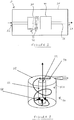
- Figure 1 shows a vacuum cleaner 10 comprising: a body 20 defining an air inlet 22, an air outlet 24, and a passageway 26 extending therebetween; an electrostatic dust filter 30 for removing dust from air as it passes through passageway 26; and an air pump 40 for drawing air into air inlet 22 and through passageway 26 to air outlet 24.
- air inlet 22 and air outlet 24 are shown on opposed sides of body 20 in the schematic illustration, air inlet 22 and air outlet 24 may be arranged to be adjacent one another or preferably in a concentric relationship at the dust entry location (e.g. with air outlet 24 surrounding a wand brush head of the vacuum cleaner).
- Electrostatic dust filter 30 has two main functions: 1) to control the electrostatic charge on dust particles passing through passageway 26 so that the dust particles can be electrostatically filtered out; and 2) sterilisation of the air passing through passageway 26.
- vacuum cleaner 10 may be further configured to control the electrostatic charge on air exiting the passageway 26 via the air outlet 24 (e.g. to allow the vacuum cleaner to exhaust or otherwise emit air of a beneficial and typically negative state of ionization).
- Electrostatic dust filter 30 comprises an electrode arrangement 32 configured to kill microorganisms (e.g. bacteria and bugs) present in air passing through the vacuum cleaner by exposing air to a voltage in excess of a threshold voltage of at least 1000 V and configured to substantially sterilise air passing through the passageway.
- the threshold voltage is at least 10,000 V.
- the facility to control the ionization state of the air/dust particles and sterilise the air can be implemented in a number of ways.
- electrostatic dust filter 30 may comprise an ionising chamber configured to operate with an active input of power and constructed to provide minimum impedance to airflow whilst the chamber is fitted with an electrode arrangement 32 (e.g. two or more plate electrodes) powered so as to maintain an electrical field of adequate length in the airflow direction to ensure capture of a suitable proportion of dust particles (e.g. substantially all particles in the case that the ionising chamber is the only or primary dust filter of the vacuum cleaner). This applies to dust extraction of incoming air and also to beneficial ionization of outgoing air.
- an electrode arrangement 32 e.g. two or more plate electrodes
- electrostatic dust filter may comprise an electrode arrangement 32 in the form of an electrostatic filter screen comprising an electrically conductive body connected to a pulsed capacitor energy store.
- the surface of the filter screen may be coated with a triboelectric material that is at the negative end of the triboelectric series and thus develops a negative charge as the airflow passes over the surface.
- the coating is selected to be sufficiently thin (e.g. 5 nm or less in thickness) so as to allow quantum tunnelling of current through to the electrically conductive body. This results in the airflow being charged positive as it leaves the filter and an accumulation of electrons in the energy store.
- Air pump 40 may comprise any means for generating a vacuum including but not limited to a vacuum impeller, a Tesla turbine and an electrostatic fluid accelerator (EFA).
- electrode arrangement 32 may provides a motive force to drive an electrostatic motor mechanically coupled to the air pump or may even be configured to provide a motive force to directly drive the air pump (see discussion of Tesla turbine embodiment below).
- an active part (e.g. moving blades) of air pump 40 may include an electrically conductive underlayer with a thin (e.g. 5 nm or less in thickness) triboelectric layer, this time at the positive end of the scale and thus configured to develop a positive charge by delivering electrons to the positive charge of the moving air/particles.
- the positive charge is stored on the opposite side of the energy store and provides a balance to the negative store side. This stored charge may be used as part of the cleaning/purifying ionization/filtering process.
- FIG. 2 shows an optional cyclonic electrostatic dust filter stage 50 for use in combination with electrostatic dust filter 30.
- Cyclonic filter stage 50 comprises a cylindrical chamber 52 including an entry port 54 at an upper end thereof and a hollow central cylindrical exit tube 56 defining a plurality of exit holes 58 at a lower end thereof.
- Dust laden air is drawn in via entry port 54 from where it is directed towards the lower exit holes 58 following a circular motion principally against an electrically conductive chamber inner wall 52A of chamber 52 which is electrically connected to one terminal of a DC supply.
- the dust particles are attracted to the electrically conductive inner wall 52A and this together with the centrifugal force causes the dust to separate from the airflow and be retained on chamber inner wall 52A. Meanwhile the air exits chamber 52 via outlet 59 at an upper end of central exit tube 56.
- chamber inner wall 52A Since it is advantageous for chamber inner wall 52A to have a large surface area so as to better attract more dust particles, the surface can be corrugated in the vertical direction providing a localized degree of turbulence and extra surface to retain dust.
- the polarity of inner wall surface can be positive or negative to suit the circumstance of the particular type of dust and conditions that prevail in the local atmosphere.
- Central exit tube 56 is electrically connected to the opposite DC supply connection to that of chamber inner wall 52A. Thus there is an electric field across the space between central exit tube 56 and chamber inner wall 52A. This field acts on the dust particles to attract them to chamber inner wall 52A.
- chamber 52 When chamber 52 is substantially full with dust particles it can be emptied by allowing chamber inner wall 52A to be connected to a ground or earth connection rather than the DC supply terminal. This allows for charge built up in and on the dust particles to be partially discharged and the dust to be free of its attraction to chamber inner wall 52A.
- Chamber 52 may be followed by a second chamber (not shown) of similar function wherein any remnant particles of dust are captured, before the transport air is directed towards an exit to atmosphere point.
- the vacuum cleaner 10 may optionally balance the net charge carried by the airstream so that an overall negative charge state exists on exit from the vacuum cleaner.
- conductive chamber inner wall 52A comprises a conductive substrate coated with a thin coating of insulating material, preferably though not exclusively a ceramic material, chosen to have maximum triboelectric properties and as such readily gives up or accepts electrons as a consequence of friction with the dust particles passing over its surface.
- the coating is very thin (e.g. no greater than 5nm in thickness) to allow quantum tunnelling to take place and allow charge to migrate to the conductive substrate and thus provides a current flow into a suitable storage device such as a capacitor or alternatively directly into a load circuit of some kind.
- the polarity in the cyclonic filter stage 50 can be reversed so that the air leaving chamber 52 has a positive charge state.
- the outgoing air may be passed through a conditioner stage that removes the positive charge and gives the air with a negative charge - thus again improving the overall air quality. It can also be arranged to further trap/remove any remnant dust particles.
- This charge flow is thus an energy extraction system taking electrical energy from the kinetic air flow. The energy can either be accumulated to be used to power the process itself, or be extracted for other purposes (e.g. powering another part of the vacuum cleaner).
- electrostatic cyclonic filter stage 50 examples include a series of vertically orientated electrodes instead of a continuous conductive substrate, each electrode connected to a different phase of control. By sequencing the energisation of the electrodes, a rotating electric field can be established. The rotating field can be used to both drive the flow of air and dust particles and also to sequence the collection of triboelectric generated electron flow.
- Either arrangement can be organized to be conical in form so that velocities of the rotating flows can be optimized.
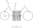
- FIG. 3 shows a Tesla turbine impeller device 60 for use as air pump 40 in vacuum cleaner 10 in accordance with an embodiment of the claimed invention.
- Tesla turbine 60 comprising an arrangement of rotor discs 62 are mounted on a common axis spaced between interposed stator discs 64 with a running clearance 66.
- the resultant electrostatic charge further enhances the drag and hence the pumping effectiveness, whilst at the same time providing for either or both, air quality improvement and or dust particle ionization.
- the dust ionization/charging can then subsequently be used to filter out the dust by collection on suitably charged plates following the turbine stage.
- rotor and stator discs 62, 64 may be coated with a thin (e.g. less than 5 nm in thickness) triboelectric coating to induce friction generated electron flow and collection via quantum tunneling effect to a substrate conductor or conductors.
- stator discs of a Tesla turbine device By suitably arranging electrodes radially on the stator discs of a Tesla turbine device (e.g. based on the principles of known electrostatic motors), it is possible to provide an electrostatic force that spins rotor discs 62 relative to stator discs 64.
- the motor can also perform as the air pump (e.g. impeller) as the air movement is required to be the same as a simple Tesla turbine impeller. That is the motor rotors and stators are the turbine rotors and stators 62, 64.
Landscapes
- Engineering & Computer Science (AREA)
- Mechanical Engineering (AREA)
- Filters For Electric Vacuum Cleaners (AREA)
- Electrostatic Separation (AREA)
- Electric Suction Cleaners (AREA)
- Electric Vacuum Cleaner (AREA)
- Cyclones (AREA)
Claims (6)
- Aspirateur (10) comprenant :un corps (20) définissant une entrée d'air (22), une sortie d'air (24), et un passage (26) s'étendant entre elles ;un filtre à poussière (30) pour éliminer la poussière de l'air lorsqu'il traverse le passage (26) ; etune pompe à air (40) pour aspirer l'air dans l'entrée d'air (22) et à travers le passage (26) vers la sortie d'air (24) ;caractérisé en ce que l'aspirateur (10) comprend en outre un agencement d'électrodes (32) permettant de fournir une force motrice pour entraîner un moteur électrostatique accouplé mécaniquement à la pompe à air (40) ou pour fournir une force motrice pour entraîner directement la pompe à air (40).
- Aspirateur (10) selon la revendication 1, la pompe à air (40) comprenant une turbine Tesla (60) comprenant au moins un disque de stator (64) en combinaison avec au moins un disque de rotor (62) et l'agencement d'électrodes (32) étant disposé sur l'au moins un disque de stator (64) pour engendrer la rotation du disque de rotor (62) correspondant.
- Aspirateur (10) selon la revendication 1 ou 2, le passage (26) ou un composant situé dans le passage (26) comprenant une surface de contact de flux d'air comprenant un revêtement triboélectrique disposé sur une sous-couche électroconductrice conçue pour fournir une tension à l'agencement d'électrodes (32).
- Aspirateur (10) selon l'une quelconque des revendications précédentes, la pompe à air (40) comprenant un élément actif comprenant une surface de contact de flux d'air comprenant un revêtement triboélectrique disposé sur une couche électroconductrice conçue pour fournir une tension à l'agencement d'électrodes (32).
- Aspirateur (10) selon l'une quelconque des revendications précédentes, le filtre à poussière (30) étant un filtre à poussière électrostatique comprenant un étage de filtre cyclonique (50) comprenant une surface de contact de flux d'air cyclonique (52A) comprenant un revêtement triboélectrique disposé sur une sous-couche électroconductrice conçue pour fournir une tension à l'agencement d'électrodes (32).
- Aspirateur (10) selon l'une quelconque des revendications précédentes, l'aspirateur (10) étant conçu pour générer un flux d'air ionisé à travers la sortie d'air.
Applications Claiming Priority (2)
| Application Number | Priority Date | Filing Date | Title |
|---|---|---|---|
| GBGB1311451.7A GB201311451D0 (en) | 2013-06-27 | 2013-06-27 | Vacuum Cleaner |
| PCT/GB2014/051927 WO2014207449A2 (fr) | 2013-06-27 | 2014-06-24 | Aspirateur |
Publications (2)
| Publication Number | Publication Date |
|---|---|
| EP3013204A2 EP3013204A2 (fr) | 2016-05-04 |
| EP3013204B1 true EP3013204B1 (fr) | 2018-10-24 |
Family
ID=48999054
Family Applications (1)
| Application Number | Title | Priority Date | Filing Date |
|---|---|---|---|
| EP14744890.6A Not-in-force EP3013204B1 (fr) | 2013-06-27 | 2014-06-24 | Aspirateur avec filtre électrostatique |
Country Status (8)
| Country | Link |
|---|---|
| US (1) | US10231586B2 (fr) |
| EP (1) | EP3013204B1 (fr) |
| JP (1) | JP6465875B2 (fr) |
| CN (1) | CN105358029A (fr) |
| BR (1) | BR112015032551A2 (fr) |
| GB (1) | GB201311451D0 (fr) |
| RU (1) | RU2667238C2 (fr) |
| WO (1) | WO2014207449A2 (fr) |
Families Citing this family (2)
| Publication number | Priority date | Publication date | Assignee | Title |
|---|---|---|---|---|
| US11957295B2 (en) * | 2021-12-02 | 2024-04-16 | Richard HILLERY | Pneumatic vacuum cleaner |
| CN115870753B (zh) * | 2022-12-27 | 2025-07-22 | 奥钢联型材(中国)有限公司 | 一种气体发生器钢管件的生产装置 |
Family Cites Families (25)
| Publication number | Priority date | Publication date | Assignee | Title |
|---|---|---|---|---|
| GB1501927A (en) | 1976-08-26 | 1978-02-22 | Bates W | Vacuum cleaner |
| JPH0182705U (fr) * | 1987-11-20 | 1989-06-01 | ||
| US5150499A (en) * | 1990-11-16 | 1992-09-29 | Shop Vac Corporation | Static electric discharge for dust collector |
| US5400465A (en) * | 1994-03-30 | 1995-03-28 | Home Care Industries, Inc. | Vacuum cleaner with charge generator and bag therefor |
| JPH09182705A (ja) * | 1995-12-28 | 1997-07-15 | Nec Home Electron Ltd | 電気掃除機 |
| IT1284447B1 (it) | 1996-06-27 | 1998-05-21 | Candy Spa | Aspirapolvere a elettro-ciclone e relativa cartuccia filtro a elettro-ciclone |
| EP0908121B1 (fr) * | 1997-07-28 | 2002-10-16 | CANDY S.p.A. | Aspirateur de poussières à effet électrostatique généré directement |
| JPH11353540A (ja) * | 1998-06-08 | 1999-12-24 | Fuji Denki Reiki Co Ltd | 自動販売機 |
| US20040035093A1 (en) * | 1999-01-08 | 2004-02-26 | Conrad Wayne Ernest | Vacuum cleaner |
| JP2001017361A (ja) * | 1999-07-07 | 2001-01-23 | Matsushita Electric Ind Co Ltd | 電気掃除機 |
| JP2001037687A (ja) * | 1999-08-02 | 2001-02-13 | Matsushita Electric Ind Co Ltd | 電気掃除機 |
| US6198195B1 (en) | 1999-10-12 | 2001-03-06 | Oreck Holdings, Llc | High efficiency motor for low velocity, high volume fan and other applications |
| CA2339514A1 (fr) * | 2001-03-06 | 2002-09-06 | Wayne Ernest Conrad | Aspirateur faisant appel au filtrage electrostatique et depoussiereur electrique connexe |
| CN1264466C (zh) * | 2001-11-19 | 2006-07-19 | 乐金电子(天津)电器有限公司 | 真空吸尘器用旋风集尘装置 |
| AU2002258715A1 (en) * | 2002-04-04 | 2003-10-20 | Illusion Technologies, Llc | Miniature/micro scale power generation system |
| JP2004013582A (ja) * | 2002-06-07 | 2004-01-15 | Nissan Motor Co Ltd | 静電気充電式管理タグ |
| TW587768U (en) * | 2003-01-30 | 2004-05-11 | Molex Inc | Heat-dissipating device |
| KR20060026574A (ko) | 2004-09-21 | 2006-03-24 | 삼성광주전자 주식회사 | 사이클론 집진장치 |
| US8292979B2 (en) * | 2006-03-10 | 2012-10-23 | G.B.D. Corp | Vacuum cleaner with a removable screen |
| JP2007244526A (ja) * | 2006-03-14 | 2007-09-27 | Sharp Corp | 電気機器 |
| CN100420416C (zh) * | 2006-04-06 | 2008-09-24 | 苏州金莱克家用电器有限公司 | 多进风口分离装置及含有该装置的尘杯装置 |
| KR101610186B1 (ko) * | 2009-06-17 | 2016-04-07 | 삼성전자주식회사 | 제진 먼지 제거 기능을 가지는 진공청소기의 집진장치 |
| GB2472095A (en) * | 2009-07-24 | 2011-01-26 | Dyson Technology Ltd | Vacuum cleaner with cyclone and electrostatic filter arrangement |
| GB2472097B (en) | 2009-07-24 | 2013-04-17 | Dyson Technology Ltd | Separating apparatus with electrostatic filter |
| DE102009038230A1 (de) * | 2009-08-20 | 2011-02-24 | Heinrich Essers Gmbh & Co. Kg | Feststofffilter, insbesondere für einen Staubsauger, und Staubsauger mit einem Feststofffilter |
-
2013
- 2013-06-27 GB GBGB1311451.7A patent/GB201311451D0/en not_active Ceased
-
2014
- 2014-06-24 US US14/899,517 patent/US10231586B2/en not_active Expired - Fee Related
- 2014-06-24 CN CN201480037122.6A patent/CN105358029A/zh active Pending
- 2014-06-24 EP EP14744890.6A patent/EP3013204B1/fr not_active Not-in-force
- 2014-06-24 JP JP2016522861A patent/JP6465875B2/ja not_active Expired - Fee Related
- 2014-06-24 RU RU2015152548A patent/RU2667238C2/ru active
- 2014-06-24 BR BR112015032551A patent/BR112015032551A2/pt not_active IP Right Cessation
- 2014-06-24 WO PCT/GB2014/051927 patent/WO2014207449A2/fr not_active Ceased
Non-Patent Citations (1)
| Title |
|---|
| None * |
Also Published As
| Publication number | Publication date |
|---|---|
| WO2014207449A3 (fr) | 2015-04-09 |
| CN105358029A (zh) | 2016-02-24 |
| RU2667238C2 (ru) | 2018-09-17 |
| JP2016527936A (ja) | 2016-09-15 |
| EP3013204A2 (fr) | 2016-05-04 |
| JP6465875B2 (ja) | 2019-02-06 |
| US10231586B2 (en) | 2019-03-19 |
| GB201311451D0 (en) | 2013-08-14 |
| RU2015152548A3 (fr) | 2018-05-23 |
| US20160150930A1 (en) | 2016-06-02 |
| BR112015032551A2 (pt) | 2017-07-25 |
| RU2015152548A (ru) | 2017-08-01 |
| WO2014207449A2 (fr) | 2014-12-31 |
Similar Documents
| Publication | Publication Date | Title |
|---|---|---|
| EP2456342B1 (fr) | Filtre électrostatique | |
| EP2279685B1 (fr) | Appareil de séparation cyclonique avec filtre électrostatique | |
| US4976749A (en) | Air filter and particle removal system | |
| US20020134238A1 (en) | Vacuum cleaner utilizing electrostatic filtration and electrostatic precipitator for use therein | |
| US20100236012A1 (en) | Cleaning and/or filtering apparatus | |
| JP2022508871A (ja) | 空気除塵システム及び方法 | |
| CN100571882C (zh) | 电除尘器 | |
| CN109297062A (zh) | 静电离心组合式油烟净化器 | |
| EP3013204B1 (fr) | Aspirateur avec filtre électrostatique | |
| JP4889386B2 (ja) | 電気掃除機 | |
| KR102094907B1 (ko) | 사이클론 살균 집진 유닛 | |
| JP4971472B2 (ja) | 電気掃除機 | |
| JP2006180937A (ja) | 電気掃除機 | |
| CN2507563Y (zh) | 磁控静电除尘器 | |
| CN101500713B (zh) | 清洁和/或过滤设备 | |
| WO1995017239A1 (fr) | Appareil permettant d'enlever des particules d'un fluide | |
| CN115301408A (zh) | 双极离子旋风凝并式空气净化装置和方法 | |
| KR20200050080A (ko) | 미세먼지 및 초미세먼지의 제거가 가능한 싸이클론 모듈 | |
| JP5486617B2 (ja) | 電気掃除機 | |
| JP2007159654A (ja) | 電気掃除機 | |
| KR19980074238A (ko) | 코로나 방전에 의한 정전여과포 집진방법 및 그 장치 | |
| KR20180131773A (ko) | 전기장을 이용한 싸이클론 방식의 공기청정기 | |
| KR20180131774A (ko) | 전기장을 이용한 싸이클론 방식의 공기청정기 | |
| KR970003860B1 (ko) | 전기 집진기 | |
| KR20240075965A (ko) | 소형 집진기 |
Legal Events
| Date | Code | Title | Description |
|---|---|---|---|
| PUAI | Public reference made under article 153(3) epc to a published international application that has entered the european phase |
Free format text: ORIGINAL CODE: 0009012 |
|
| 17P | Request for examination filed |
Effective date: 20160118 |
|
| AK | Designated contracting states |
Kind code of ref document: A2 Designated state(s): AL AT BE BG CH CY CZ DE DK EE ES FI FR GB GR HR HU IE IS IT LI LT LU LV MC MK MT NL NO PL PT RO RS SE SI SK SM TR |
|
| AX | Request for extension of the european patent |
Extension state: BA ME |
|
| DAX | Request for extension of the european patent (deleted) | ||
| STAA | Information on the status of an ep patent application or granted ep patent |
Free format text: STATUS: EXAMINATION IS IN PROGRESS |
|
| 17Q | First examination report despatched |
Effective date: 20170518 |
|
| GRAP | Despatch of communication of intention to grant a patent |
Free format text: ORIGINAL CODE: EPIDOSNIGR1 |
|
| STAA | Information on the status of an ep patent application or granted ep patent |
Free format text: STATUS: GRANT OF PATENT IS INTENDED |
|
| INTG | Intention to grant announced |
Effective date: 20180509 |
|
| GRAS | Grant fee paid |
Free format text: ORIGINAL CODE: EPIDOSNIGR3 |
|
| GRAA | (expected) grant |
Free format text: ORIGINAL CODE: 0009210 |
|
| STAA | Information on the status of an ep patent application or granted ep patent |
Free format text: STATUS: THE PATENT HAS BEEN GRANTED |
|
| AK | Designated contracting states |
Kind code of ref document: B1 Designated state(s): AL AT BE BG CH CY CZ DE DK EE ES FI FR GB GR HR HU IE IS IT LI LT LU LV MC MK MT NL NO PL PT RO RS SE SI SK SM TR |
|
| REG | Reference to a national code |
Ref country code: CH Ref legal event code: EP |
|
| REG | Reference to a national code |
Ref country code: IE Ref legal event code: FG4D |
|
| REG | Reference to a national code |
Ref country code: AT Ref legal event code: REF Ref document number: 1055678 Country of ref document: AT Kind code of ref document: T Effective date: 20181115 |
|
| REG | Reference to a national code |
Ref country code: DE Ref legal event code: R096 Ref document number: 602014034652 Country of ref document: DE |
|
| REG | Reference to a national code |
Ref country code: NL Ref legal event code: MP Effective date: 20181024 |
|
| REG | Reference to a national code |
Ref country code: LT Ref legal event code: MG4D |
|
| REG | Reference to a national code |
Ref country code: AT Ref legal event code: MK05 Ref document number: 1055678 Country of ref document: AT Kind code of ref document: T Effective date: 20181024 |
|
| PG25 | Lapsed in a contracting state [announced via postgrant information from national office to epo] |
Ref country code: NL Free format text: LAPSE BECAUSE OF FAILURE TO SUBMIT A TRANSLATION OF THE DESCRIPTION OR TO PAY THE FEE WITHIN THE PRESCRIBED TIME-LIMIT Effective date: 20181024 |
|
| PG25 | Lapsed in a contracting state [announced via postgrant information from national office to epo] |
Ref country code: LV Free format text: LAPSE BECAUSE OF FAILURE TO SUBMIT A TRANSLATION OF THE DESCRIPTION OR TO PAY THE FEE WITHIN THE PRESCRIBED TIME-LIMIT Effective date: 20181024 Ref country code: AT Free format text: LAPSE BECAUSE OF FAILURE TO SUBMIT A TRANSLATION OF THE DESCRIPTION OR TO PAY THE FEE WITHIN THE PRESCRIBED TIME-LIMIT Effective date: 20181024 Ref country code: BG Free format text: LAPSE BECAUSE OF FAILURE TO SUBMIT A TRANSLATION OF THE DESCRIPTION OR TO PAY THE FEE WITHIN THE PRESCRIBED TIME-LIMIT Effective date: 20190124 Ref country code: LT Free format text: LAPSE BECAUSE OF FAILURE TO SUBMIT A TRANSLATION OF THE DESCRIPTION OR TO PAY THE FEE WITHIN THE PRESCRIBED TIME-LIMIT Effective date: 20181024 Ref country code: FI Free format text: LAPSE BECAUSE OF FAILURE TO SUBMIT A TRANSLATION OF THE DESCRIPTION OR TO PAY THE FEE WITHIN THE PRESCRIBED TIME-LIMIT Effective date: 20181024 Ref country code: IS Free format text: LAPSE BECAUSE OF FAILURE TO SUBMIT A TRANSLATION OF THE DESCRIPTION OR TO PAY THE FEE WITHIN THE PRESCRIBED TIME-LIMIT Effective date: 20190224 Ref country code: NO Free format text: LAPSE BECAUSE OF FAILURE TO SUBMIT A TRANSLATION OF THE DESCRIPTION OR TO PAY THE FEE WITHIN THE PRESCRIBED TIME-LIMIT Effective date: 20190124 Ref country code: HR Free format text: LAPSE BECAUSE OF FAILURE TO SUBMIT A TRANSLATION OF THE DESCRIPTION OR TO PAY THE FEE WITHIN THE PRESCRIBED TIME-LIMIT Effective date: 20181024 Ref country code: ES Free format text: LAPSE BECAUSE OF FAILURE TO SUBMIT A TRANSLATION OF THE DESCRIPTION OR TO PAY THE FEE WITHIN THE PRESCRIBED TIME-LIMIT Effective date: 20181024 Ref country code: PL Free format text: LAPSE BECAUSE OF FAILURE TO SUBMIT A TRANSLATION OF THE DESCRIPTION OR TO PAY THE FEE WITHIN THE PRESCRIBED TIME-LIMIT Effective date: 20181024 |
|
| PG25 | Lapsed in a contracting state [announced via postgrant information from national office to epo] |
Ref country code: SE Free format text: LAPSE BECAUSE OF FAILURE TO SUBMIT A TRANSLATION OF THE DESCRIPTION OR TO PAY THE FEE WITHIN THE PRESCRIBED TIME-LIMIT Effective date: 20181024 Ref country code: GR Free format text: LAPSE BECAUSE OF FAILURE TO SUBMIT A TRANSLATION OF THE DESCRIPTION OR TO PAY THE FEE WITHIN THE PRESCRIBED TIME-LIMIT Effective date: 20190125 Ref country code: PT Free format text: LAPSE BECAUSE OF FAILURE TO SUBMIT A TRANSLATION OF THE DESCRIPTION OR TO PAY THE FEE WITHIN THE PRESCRIBED TIME-LIMIT Effective date: 20190224 Ref country code: AL Free format text: LAPSE BECAUSE OF FAILURE TO SUBMIT A TRANSLATION OF THE DESCRIPTION OR TO PAY THE FEE WITHIN THE PRESCRIBED TIME-LIMIT Effective date: 20181024 Ref country code: RS Free format text: LAPSE BECAUSE OF FAILURE TO SUBMIT A TRANSLATION OF THE DESCRIPTION OR TO PAY THE FEE WITHIN THE PRESCRIBED TIME-LIMIT Effective date: 20181024 |
|
| REG | Reference to a national code |
Ref country code: DE Ref legal event code: R097 Ref document number: 602014034652 Country of ref document: DE |
|
| PG25 | Lapsed in a contracting state [announced via postgrant information from national office to epo] |
Ref country code: CZ Free format text: LAPSE BECAUSE OF FAILURE TO SUBMIT A TRANSLATION OF THE DESCRIPTION OR TO PAY THE FEE WITHIN THE PRESCRIBED TIME-LIMIT Effective date: 20181024 Ref country code: DK Free format text: LAPSE BECAUSE OF FAILURE TO SUBMIT A TRANSLATION OF THE DESCRIPTION OR TO PAY THE FEE WITHIN THE PRESCRIBED TIME-LIMIT Effective date: 20181024 Ref country code: IT Free format text: LAPSE BECAUSE OF FAILURE TO SUBMIT A TRANSLATION OF THE DESCRIPTION OR TO PAY THE FEE WITHIN THE PRESCRIBED TIME-LIMIT Effective date: 20181024 |
|
| PG25 | Lapsed in a contracting state [announced via postgrant information from national office to epo] |
Ref country code: SK Free format text: LAPSE BECAUSE OF FAILURE TO SUBMIT A TRANSLATION OF THE DESCRIPTION OR TO PAY THE FEE WITHIN THE PRESCRIBED TIME-LIMIT Effective date: 20181024 Ref country code: RO Free format text: LAPSE BECAUSE OF FAILURE TO SUBMIT A TRANSLATION OF THE DESCRIPTION OR TO PAY THE FEE WITHIN THE PRESCRIBED TIME-LIMIT Effective date: 20181024 Ref country code: SM Free format text: LAPSE BECAUSE OF FAILURE TO SUBMIT A TRANSLATION OF THE DESCRIPTION OR TO PAY THE FEE WITHIN THE PRESCRIBED TIME-LIMIT Effective date: 20181024 Ref country code: EE Free format text: LAPSE BECAUSE OF FAILURE TO SUBMIT A TRANSLATION OF THE DESCRIPTION OR TO PAY THE FEE WITHIN THE PRESCRIBED TIME-LIMIT Effective date: 20181024 |
|
| PLBE | No opposition filed within time limit |
Free format text: ORIGINAL CODE: 0009261 |
|
| STAA | Information on the status of an ep patent application or granted ep patent |
Free format text: STATUS: NO OPPOSITION FILED WITHIN TIME LIMIT |
|
| 26N | No opposition filed |
Effective date: 20190725 |
|
| PG25 | Lapsed in a contracting state [announced via postgrant information from national office to epo] |
Ref country code: SI Free format text: LAPSE BECAUSE OF FAILURE TO SUBMIT A TRANSLATION OF THE DESCRIPTION OR TO PAY THE FEE WITHIN THE PRESCRIBED TIME-LIMIT Effective date: 20181024 |
|
| REG | Reference to a national code |
Ref country code: DE Ref legal event code: R119 Ref document number: 602014034652 Country of ref document: DE |
|
| PG25 | Lapsed in a contracting state [announced via postgrant information from national office to epo] |
Ref country code: MC Free format text: LAPSE BECAUSE OF FAILURE TO SUBMIT A TRANSLATION OF THE DESCRIPTION OR TO PAY THE FEE WITHIN THE PRESCRIBED TIME-LIMIT Effective date: 20181024 |
|
| REG | Reference to a national code |
Ref country code: CH Ref legal event code: PL |
|
| GBPC | Gb: european patent ceased through non-payment of renewal fee |
Effective date: 20190624 |
|
| REG | Reference to a national code |
Ref country code: BE Ref legal event code: MM Effective date: 20190630 |
|
| PG25 | Lapsed in a contracting state [announced via postgrant information from national office to epo] |
Ref country code: TR Free format text: LAPSE BECAUSE OF FAILURE TO SUBMIT A TRANSLATION OF THE DESCRIPTION OR TO PAY THE FEE WITHIN THE PRESCRIBED TIME-LIMIT Effective date: 20181024 |
|
| PG25 | Lapsed in a contracting state [announced via postgrant information from national office to epo] |
Ref country code: GB Free format text: LAPSE BECAUSE OF NON-PAYMENT OF DUE FEES Effective date: 20190624 Ref country code: IE Free format text: LAPSE BECAUSE OF NON-PAYMENT OF DUE FEES Effective date: 20190624 Ref country code: DE Free format text: LAPSE BECAUSE OF NON-PAYMENT OF DUE FEES Effective date: 20200101 |
|
| PG25 | Lapsed in a contracting state [announced via postgrant information from national office to epo] |
Ref country code: LI Free format text: LAPSE BECAUSE OF NON-PAYMENT OF DUE FEES Effective date: 20190630 Ref country code: BE Free format text: LAPSE BECAUSE OF NON-PAYMENT OF DUE FEES Effective date: 20190630 Ref country code: CH Free format text: LAPSE BECAUSE OF NON-PAYMENT OF DUE FEES Effective date: 20190630 Ref country code: LU Free format text: LAPSE BECAUSE OF NON-PAYMENT OF DUE FEES Effective date: 20190624 |
|
| PG25 | Lapsed in a contracting state [announced via postgrant information from national office to epo] |
Ref country code: FR Free format text: LAPSE BECAUSE OF NON-PAYMENT OF DUE FEES Effective date: 20190630 |
|
| PG25 | Lapsed in a contracting state [announced via postgrant information from national office to epo] |
Ref country code: CY Free format text: LAPSE BECAUSE OF FAILURE TO SUBMIT A TRANSLATION OF THE DESCRIPTION OR TO PAY THE FEE WITHIN THE PRESCRIBED TIME-LIMIT Effective date: 20181024 |
|
| PG25 | Lapsed in a contracting state [announced via postgrant information from national office to epo] |
Ref country code: MT Free format text: LAPSE BECAUSE OF FAILURE TO SUBMIT A TRANSLATION OF THE DESCRIPTION OR TO PAY THE FEE WITHIN THE PRESCRIBED TIME-LIMIT Effective date: 20181024 Ref country code: HU Free format text: LAPSE BECAUSE OF FAILURE TO SUBMIT A TRANSLATION OF THE DESCRIPTION OR TO PAY THE FEE WITHIN THE PRESCRIBED TIME-LIMIT; INVALID AB INITIO Effective date: 20140624 |
|
| PG25 | Lapsed in a contracting state [announced via postgrant information from national office to epo] |
Ref country code: MK Free format text: LAPSE BECAUSE OF FAILURE TO SUBMIT A TRANSLATION OF THE DESCRIPTION OR TO PAY THE FEE WITHIN THE PRESCRIBED TIME-LIMIT Effective date: 20181024 |